1
GE Fanuc Automation
Programmable Control Products
Host Drivers and Communications Configuration
Software
for Windows® Environments
User's Manual
GFK-1026C
November 1998
GFL-002
Warnings, Cautions, and Notes
as Used in this Publication
Warning
Warning notices are used in this publication to emphasize that hazardous voltages,
currents, temperatures, or other conditions that could cause personal injury exist in this
equipment or may be associated with its use.
In situations where inattention could cause either personal injury or damage to
equipment, a Warning notice is used.
Caution
Caution notices are used where equipment might be damaged if care is not taken.
Note
Notes merely call attention to information that is especially significant to understanding and
operating the equipment.
This document is based on information available at the time of its publication. While efforts
have been made to be accurate, the information contained herein does not purport to cover all
details or variations in hardware or software, nor to provide for every possible contingency in
connection with installation, operation, or maintenance. Features may be described herein
which are not present in all hardware and software systems. GE Fanuc Automation assumes
no obligation of notice to holders of this document with respect to changes subsequently made.
GE Fanuc Automation makes no representation or warranty, expressed, implied, or statutory
with respect to, and assumes no responsibility for the accuracy, completeness, sufficiency, or
usefulness of the information contained herein. No warranties of merchantability or fitness for
purpose shall apply.
The following are trademarks of GE Fanuc Automation North America, Inc.
Alarm Master
CIMPLICITY
CIMPLICITY Control
CIMPLICITY PowerTRAC
CIMPLICITY 90–ADS
CIMSTAR
Field Control
GEnet
Genius
Genius PowerTRAC
Helpmate
Logicmaster
Modelmaster
Motion Mate
PowerMotion
ProLoop
PROMACRO
Series Five
Series 90
Series One
Series Six
Series Three
VersaMax
VuMaster
Workmaster
©Copyright 1996—1998 GE Fanuc Automation North America, Inc.
All Rights Reserved.
Preface
Revisions to This Manual
The following changes have been made to this manual, GFK-1026C, as compared to the previous
version, GFK-1026B:
•
The Communication Configuration Utility supports modem configuration. This new feature is
described in Chapter 3. Changes made to the data structures (Chapter 4) and the Host Drivers
configuration file (Appendix A) to support modem configuration are also described.
•
The information in Appendix B was expanded to include Class D addresses.
•
Other corrections and clarifications, including index entries, were made as necessary.
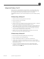
Content of This Manual
This document describes the installation and use of the GE Fanuc Host Driver software, the
Communication Configuration Utility (CCU), and the Communication Configuration Library
(CCL).
GFK-1026C
Chapter 1.
Introduction: Describes the capabilities of the Host Drivers and presents a
system overview for each platform the drivers can run on. Also introduces the
Communication Configuration Utility and the Communication Configuration
Library.
Chapter 2.
Getting Started: Explains how to install the Host Drivers and how to get started
using them.
Chapter 3.
Communication Configuration Utility: Describes the Windows executable used
to manage the Host Drivers configuration file.
Chapter 4.
Communication Configuration Library: Describes the Windows Dynamic
Link Library which provides an application programming interface that can be
used for managing the Host Drivers configuration file.
Appendix A.
Host Driver Database Descriptions: Describes the content of the Host Drivers
configuration file, GEF_CFG.INI.
Appendix B.
Advanced Information About IP Addresses: Describes how to assign IP
addresses, Default Gateway, and Subnet Mask.
iii
Preface
Related Publications
GFK-0870
Host Communications Toolkit for C/C++ Applications User’s Manual
GFK-1055
Plug & Play Coprocessor for Series 90-70 PLC User’s Manual
GFK-1063
Host Communications Toolkit for Visual Basic Applications User’s Manual
GFK-1246
TCP/IP Ethernet Communications (Type 2) for the Series 90-70 PLC
User’s Manual
GFK-1084
TCP/IP Ethernet Communications for the Series 90-30 PLC User’s Manual
GFK-1186
TCP/IP Ethernet Communications for the Series 90 PLC Station Manager Manual
GFK-1541
TCP/IP Ethernet Communications for the Series 90-30/70 PLC User's Manual
At GE Fanuc Automation, we strive to produce quality technical documentation. After you have
used this manual, please take a few moments to complete and return the Reader's Comment Card
located on the next page.
iv
Host Drivers and Communications Configuration Software User's Manual–November 1998
GFK-1026C
Contents
Chapter 1
Introduction..................................................................................................... 1-1
Host Drivers ................................................................................................................. 1-1
Stand-Alone PC Host Driver Use .......................................................................... 1-2
Plug & Play PC Host Driver Use ........................................................................... 1-2
How to Use the Drivers ................................................................................................. 1-3
Communication Configuration Utility (CCU)................................................................. 1-4
Communication Configuration Library (CCL) ............................................................... 1-4
Chapter 2
Getting Started ................................................................................................ 2-1
Section 1: Installation and Start-Up: Windows 95, Windows NT.............. 2-2
Host Requirements ........................................................................................................ 2-2
Installing the Host Drivers............................................................................................. 2-3
Section 2: Installation and Start-Up: Windows for Workgroups................ 2-4
Host Requirements ........................................................................................................ 2-4
Installing the TCP/IP Communications Stack................................................................. 2-4
Installing the Host Drivers............................................................................................. 2-5
VME Communications for the Plug & Play PC ....................................................... 2-6
Using the Host Driver Icon...................................................................................... 2-6
The Version Menu................................................................................................ 2-7
The Tallies Menu.................................................................................................. 2-7
The Quit Menu ..................................................................................................... 2-8
Chapter 3
Communication Configuration Utility ........................................................... 3-1
Configuring Communications ........................................................................................ 3-1
Running the Communication Configuration Utility......................................................... 3-2
Saving Your Work.................................................................................................. 3-2
Closing Without Saving Your Work........................................................................ 3-2
Printing .................................................................................................................. 3-2
Device (PLC) Configuration ................................................................................... 3-3
Adding a Device Configuration............................................................................. 3-4
Changing a Device Configuration ......................................................................... 3-4
Deleting a Device Configuration ........................................................................... 3-5
PC Port Configuration ............................................................................................ 3-5
Adding a PC Port Configuration ........................................................................... 3-6
Changing a PC Port Configuration ....................................................................... 3-6
Deleting a PC Port Configuration ......................................................................... 3-7
Global Parameter Configuration.............................................................................. 3-7
Configuring Global Timeouts for PC Ports............................................................ 3-8
Timeout Precedence for Connect Timeout and Request Timeout ........................... 3-8
Modem Configuration............................................................................................. 3-9
Adding a Modem Configuration ......................................................................... 3-10
Editing a Modem Configuration ......................................................................... 3-10
Deleting a Modem Configuration........................................................................ 3-10
GFK-1026C
v
Contents
Sample Device/Port Configurations ............................................................................. 3-11
DEFAULT/COM1-4........................................................................................... 3-11
ENET ................................................................................................................. 3-12
testplc/port_1...................................................................................................... 3-12
Chapter 4
Communication Configuration Library ......................................................... 4-1
Structures Used With the CCL ...................................................................................... 4-1
Structures that Apply to Multiple Record Types ............................................................ 4-1
CCL_REC.............................................................................................................. 4-1
SEARCH_KEY_DEF............................................................................................. 4-2
Port Record Structure ................................................................................................... 4-2
CCL_PORT_REC.................................................................................................. 4-3
Device Record Structure ............................................................................................... 4-4
CCL_DEV_REC .................................................................................................... 4-4
Modem Record Structure .............................................................................................. 4-5
CCL_MODEM_REC ............................................................................................. 4-5
Global Parameters Structure.......................................................................................... 4-5
CCL_GP_REC....................................................................................................... 4-5
CCL Interface Routines for C/C++ Applications ........................................................... 4-6
CCL_Add_Record .................................................................................................. 4-6
CCL_Delete_Record............................................................................................... 4-9
CCL_Get_Record................................................................................................. 4-10
CCL_Get_List...................................................................................................... 4-11
CCL_Get_Version ................................................................................................ 4-13
Appendix A
Configuration File Description .......................................................................A-1
General Record Description for the Configuration File.................................................. A-1
Generic Format...................................................................................................... A-1
Record Formation Rules ........................................................................................ A-2
Port Records ................................................................................................................ A-2
Port Name ............................................................................................................. A-2
Communications Type ........................................................................................... A-3
Port-Specific Timeout Parameters .......................................................................... A-3
Port Communications Parameters........................................................................... A-3
Port Record Keywords ........................................................................................... A-3
BAUDRATE Keyword......................................................................................... A-4
CONNECT_TIMEOUT Keyword ........................................................................ A-5
MODEM_RECORDNAME ................................................................................. A-5
MODEM_TURN Keyword .................................................................................. A-5
MULTISESS Keyword......................................................................................... A-5
PARITY Keyword ............................................................................................... A-6
PORT Keyword ................................................................................................... A-6
REQUEST_TIMEOUT Keyword ......................................................................... A-6
vi
Host Drivers and Communications Configuration Software User's Manual–November 1998
GFK-1026C
Contents
SNP_T1 Keyword ................................................................................................ A-6
SNP_T2 Keyword ................................................................................................ A-6
SNP_T3 Keyword ................................................................................................ A-7
SNP_T3P Keyword.............................................................................................. A-7
SNP_T3PP Keyword............................................................................................ A-7
SNP_T4 Keyword ................................................................................................ A-7
SNP_T5 Keyword ................................................................................................ A-8
SNP_T5P Keyword.............................................................................................. A-8
SNP_T5PP Keyword............................................................................................ A-8
STOPBITS Keyword............................................................................................ A-8
TYPE Keyword.................................................................................................... A-8
Sample Port Record Entries ................................................................................... A-9
Device Records .......................................................................................................... A-10
Device Name ....................................................................................................... A-10
Addressing Information........................................................................................ A-10
Ethernet LAN Addressing (TCP/IP or SLIP)...................................................... A-10
VMEbus Addressing.......................................................................................... A-11
SNP/Serial Addressing ...................................................................................... A-11
Default Port Name............................................................................................... A-11
Device Model Information.................................................................................... A-11
Device Record Keywords ..................................................................................... A-12
DEFAULT_PORT Keyword .............................................................................. A-12
DEST_ADDR Keyword ..................................................................................... A-12
IP_ADDR Keyword ........................................................................................... A-12
SNP_ID Keyword .............................................................................................. A-12
MODEM_RECORD_NAME ............................................................................. A-13
Sample Device Record Database Entry................................................................. A-13
Modem Records ......................................................................................................... A-14
Modem Name ...................................................................................................... A-14
Modem Record Keywords.................................................................................... A-14
MODEM_DIAL ................................................................................................ A-14
MODEM_DISP ................................................................................................. A-14
MODEM_COUNTRYNAME ............................................................................ A-14
MODEM_AREACODE..................................................................................... A-15
MODEM_PHONENO ....................................................................................... A-15
MODEM_LOCATION ...................................................................................... A-15
MODEM_TAPILINE ........................................................................................ A-15
MODEM_USEDCANDA .................................................................................. A-15
MODEM_DEVICEID ....................................................................................... A-15
Global Parameters...................................................................................................... A-16
Connect Request Timeout .................................................................................... A-16
General Request Timeout ..................................................................................... A-17
Sample Global Parameter Entries ......................................................................... A-17
Time Value Resolution......................................................................................... A-17
Timeout Precedence............................................................................................. A-18
GFK-1026C
Contents
vii
Contents
Appendix B
Assigning IP Addresses ...................................................................................B-1
IP Addresses.......................................................................................................... B-1
Class D Addresses ................................................................................................. B-2
Gateways............................................................................................................... B-3
Subnets.................................................................................................................. B-3
Setting Up the IP Address of Your PC.................................................................... B-5
IP Address Setup on Windows 95 ........................................................................ B-5
IP Address Setup on Windows NT ....................................................................... B-5
IP Address Setup on Windows for Workgroups.................................................... B-6
Defining Your Own IP Address.............................................................................. B-7
viii
Host Drivers and Communications Configuration Software User's Manual–November 1998
GFK-1026C
Contents
Figure 1- 1. Host Communications Drivers Overview............................................................................... 1-1
Figure 1- 2. Host Communications Drivers Running on a Stand-Alone PC with Windows 95, Windows
for Workgroups, or Windows NT .................................................................................... 1-2
Figure 1- 3. Host Communications Drivers Running on a Plug & Play PC with Windows for
Workgroups .................................................................................................................... 1-2
Figure 1- 4. How to Use the Host Communications Drivers ...................................................................... 1-3
Figure 1- 5. Communication Configuration Utility Devices Tab................................................................ 1-4
GFK-1026C
Contents
ix
Chapter
Introduction
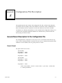
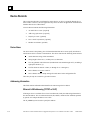
1
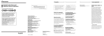
This document describes the installation and use of the GE Fanuc Host Driver software, the
Communication Configuration Utility (CCU), and the Communication Configuration Library (CCL).
Host Drivers
The Host Driver software is used in conjunction with applications created using the Host
Communications Toolkit (HCT) to communicate with GE Fanuc Series 90 PLCs. See the Preface for
references to other manuals.
a45430
Host
Communications
Toolkit Application
Host
Communications
Driver(s)
Series 90
PLCs
Figure 1- 1. Host Communications Drivers Overview.
The Host Drivers run in the Microsoft Windows NT® and Windows® 95 environments on a
stand-alone PC.
The Host Drivers also run in the Microsoft® Windows® for Workgroups environment on two
types of host platforms:
Stand-alone PC with Windows for Workgroups.
Plug & Play PC with Windows for Workgroups. This is a personal computer that plugs
directly into the Series 90-70 VME backplane.
®Microsoft, Windows, and Windows NT are registered trademarks of Microsoft Corporation.
GFK-1026C
1-1
1
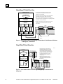
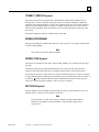
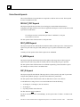
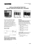
Stand-Alone PC Host Driver Use
1. A TCP/IP communications stack is required for TCP/IP
communications. See "Host Requirements" sections in
Chapter 2 for more information.
Stand-Alone PC with
Windows
Host
Application Program
2. A third-party network communications card and its associated
driver software are required for TCP/IP communications.
3. EGD supported on Windows NT systems only. For details on
which GE Fanuc PLCs support EGD and for programming software
Host
Communications
Toolkit (HCT)
requirements, contact your distributor.
Host
Communications
Driver(s)
SNP
Driver
TCP/IP
Driver
4. TCP/IP communications to a remote Series 90 PLC requires
TCP/IP Ethernet communications module in the remote
Series 90 PLC.
EGD
Interface 3
TCP/IP
Network
Transceiver
Transceiver
TCP/IP
1
Stack
Serial
COM Port
Ethernet
Card 2
EGD
Service
Series 90 PLC 4
Series 90 PLC 4
Serial
Network
Figure 1- 2. Host Communications Drivers Running on a Stand-Alone PC with Windows 95, Windows
for Workgroups, or Windows NT
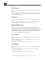
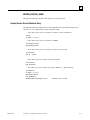
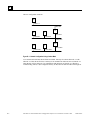
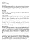
Plug & Play PC Host Driver Use
a45432
Plug & Play PC
with Windows for Workgroups
1. The Plug & Play PC communicates with
the Host Series 90-70 PLC over the VME
backplane and with a Remote Series 90
PLC via the built-in TCP/IP communications
port or the built-in serial communications port.
HOST SERIES 90-70 PLC
HOST
COMMUNICATIONS
TOOLKIT APPLICATION
HOST
COMMUNICATIONS
DRIVER(s)
VME
DRIVER
SNP
DRIVER
TCP/IP
DRIVER
2. A TCP/IP communications stack is required
for TCP/IP communications. See "Host
Requirements" sections in Chapter 2 for
more information.
1
TCP/IP
NETWORK
3. TCP/IP communications to a remote
Series 90 PLC requires a TCP/IP Ethernet
communications module in the remote
Series 90 PLC.
TRANSCEIVER
TRANSCEIVER
TCP/IP
STACK 2
TO
TO
VME
SNP
Backplane Network
TO
TCP/IP
Network
SERIES 90 PLC 3
SERIES 90 PLC 3
Figure 1- 3. Host Communications Drivers Running on a Plug & Play PC with Windows for
Workgroups
1-2
Host Drivers and Communications Configuration Software User's Manual – November 1998
GFK-1026C
1
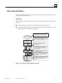
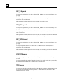
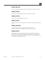
How to Use the Drivers
The figure below describes the general steps you must perform to set up a complete system using
the Host Communications Drivers.
What To Do
Before installing and using the drivers you must ensure that the host computer requirements have
been met.
For stand-alone hosts see Chapter 2, Getting Started, for system requirements.
For the Plug-and Play PC used as a host you must install the module in the host PLC. See the
Plug-and Play PC User’s Manual for information.
a45433
HOST
COMMUNICATIONS
TOOLKIT APPLICATION
HOST
COMMUNICATIONS
DRIVER(s)
SNP
TCP/IP
DRIVER
DRIVER
TCP/IP
STACK1
SERIAL
COM PORT
ETHERNET
CARD
TRANSCEIVER
Install the Host Communications Toolkit
user application. Refer to documentation
supplied by the distributor of the application.
Install the communications drivers. For a
stand-alone host refer to Chapter 2, "Getting
Started". For the Plug-and-Play PC, also see
the Plug & Play PC User's Manual.
Install the TCP/IP stack for TCP/IP
communications. Refer to Chapter 2 for
more information.
Install communications card if required.
- For stand-alone hosts you will need a
communications card. See Chapter 2 for
more information.
- For Plug & Play hosts, the communications hardware is built-in to the module for
communications to PLCs.
Install communications cabling and other
communications hardware required for the
physical network.
For TCP/IP communications you must install
a TCP/IP Ethernet module and load it with
TCP/IP software. See GFK-1541 for
information.
SERIES 90 PLC
Figure 1- 4. How to Use the Host Communications Drivers
GFK-1026C
Chapter 1 Introduction
1-3
1
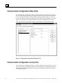
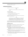
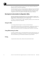
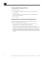
Communication Configuration Utility (CCU)
The Communication Configuration Utility is a Microsoft Windows* program used to configure
and save communications parameters. The figure below shows the Devices tab of the utility which
is used to configure the address and other optional information about the target PLC. There are
also two other tabs for creating port configurations and configuring global parameters. See Online
Help in the Communication Configuration Utility and Chapter 3 in this document for details.
*The Communication Configuration Utility runs under Windows 95 and Windows NT only.
Figure 1- 5. Communication Configuration Utility Devices Tab
Communication Configuration Library (CCL)
The Communication Configuration Library is a Windows Dynamic Link Library (DLL). The CCL
provides an application programming interface for the Communication Configuration Utility and
Host Communications Toolkit applications to manage the configuration data in GEF_CFG.INI.
See Chapter 4 for details.
1-4
Host Drivers and Communications Configuration Software User's Manual – November 1998
GFK-1026C
Chapter
Getting Started
2
This chapter provides instructions on how to install and get started using the Host
Communications Drivers. The instructions are divided into sections based upon the target
operating system:
GFK-1026C
Section 1. Windows 95 or Windows NT
Section 2. Windows for Workgroups
2-1
2
Section 1: Installation and Start-Up: Windows 95, Windows NT
Host Requirements
To be able to install and use the Host Communications Drivers to communicate with a PLC, your
system must meet the following requirements.
General Requirements
3.5 inch 1.44 Mbyte floppy drive
3 Mbytes of available hard-disk space (5 Mbytes recommended)
16 Mbytes of RAM for 1-4 HCT sessions. 32 Mbytes of RAM for more than 4 HCT sessions.
Windows 95 Specific Requirements
Windows 95 operating system
IBM PC compatible with 80486 processor (Pentium recommended)
Windows NT Specific Requirements
Windows NT version 3.51 (with service pack 5), or Windows NT version 4.0 (with service
pack 1), or later
IBM PC compatible with 80486 processor (Pentium recommended)
TCP/IP Specific Requirements
You will need a PC network card to communicate over an Ethernet network.
Refer to Appendix B if you need to install and set up the IP address of your PC.
Note
Both Windows 95 and Windows NT come with built-in TCP/IP stacks. Thus,
unlike the Windows for Workgroups environment, no separate TCP/IP stack
installation is required.
SNP Specific Requirements
2-2
You will need a Mini Converter Kit (IC690ACC901) to convert from RS-232 to RS-485.
Host Drivers and Communications Configuration Software User's Manual – November 1998
GFK-1026C
2
Installing the Host Drivers
The Host Drivers are distributed on a 3.5 inch floppy diskette.
To install the Host Drivers:
1.
Close all active applications.
2.
Insert the distribution diskette into Drive A.
3.
Choose RUN from the Windows NT Program Manager File Menu or from the Windows 95
Start menu.
4.
Type a:\setup at the command line and click OK.
The Host Drivers setup program will begin. Follow the instructions in the setup program to
complete the installation of the drivers.
Note
The Windows 95/NT Host Drivers limit their users to no more than 128
simultaneous sessions to remote PLCs. These sessions may be any combination
of up to 64 SNP and up to 64 TCP sessions, but there may be no more than 16
SNP sessions on a single COM port.
The setup program copies the following files to the Windows root director:
GFK-1026C
GEFHCT32.DLL DLL containing the Host Communications Toolkit service routines.
GEFSRX32.DLL DLL containing Communications Driver service routines.
SRXDRV.EXE The Host Communications Driver main executable.
GEFTCP.DLL DLL containing routines which provide an interface between the
communications driver service routines and the Winsock interface of the third-party
TCP/IP software. (This file is installed only if you selected the TCP/IP driver during
installation of the Host Drivers).
GEFEGD32.DLL DLL containing routines that support Ethernet Global Data
communications
GEFSNP32.DLL DLL containing routines that support Series 90 Protocol
communications
GEFCCL32.DLL DLL that provides an application programming interface for
managing the Host Drivers configuration file
GEF_CFG.INI This file contains configuration information pertaining to the remote
devices with which you wish to connect. You should not install this file if you have an
existing Host Drivers configuration file with meaningful data.
Chapter 2 Getting Started
2-3
2
Section 2: Installation and Start-Up: Windows for Workgroups
Host Requirements
To be able to install and use the Host Communications Drivers to communicate with a PLC, your
system must meet the following requirements.
General Requirements
IBM PC Compatible with 80386 processor or higher (or Plug & Play PC)
3.5 inch floppy drive
DOS 5.0 or later
Windows for Workgroups (Windows 3.11)
1 Mbyte of available hard-disk space
8 Mbytes of RAM (16 Mbytes or more recommended)
TCP/IP Specific Requirements
Third-party Windows sockets (“Winsock”) interface software (TCP/IP stack) if you are using
the TCP/IP communications driver.
For a stand-alone PC, you will need a PC network card to communicate over an Ethernet
network.
VME Specific Requirements
Only the Plug-and Play PC can use the VME driver.
Installing the TCP/IP Communications Stack
Before installing the GE Fanuc TCP/IP Host Driver, the underlying TCP/IP communications
software must first be in place. This TCP/IP software must have a Windows sockets (“Winsock”)
programming interface to support the communications drivers.
The Windows for Workgroups operating system comes with the right to obtain a copy of
Microsoft’s Winsock-compliant DLL, “Microsoft TCP/IP-32 for Windows for Workgroups.” To
obtain this TCP/IP software from Microsoft, you can contact them by calling Microsoft Sales at
800-426-9400 or by going to the Microsoft web site, www.microsoft.com
You should verify that the Winsock TCP/IP DLL is working properly by consulting Microsoft’s
installation and start-up documentation (*.TXT and *.HLP help files) before installing any of the
HCT software products listed above. In particular, it is recommended that a PING command be
successful in both directions (PC to PLC, and PLC to PC) before installing the Host
2-4
Host Drivers and Communications Configuration Software User's Manual – November 1998
GFK-1026C
2
Communications Toolkit software. This will prevent confusion later on if you are certain that the
underlying TCP/IP software is operational.
Installing the Host Drivers
The Host Drivers are distributed on a 3.5 inch floppy diskette.
Note
For Plug & Play PCs, the Host Drivers software is pre-installed on the PCMCIA
hard disk.
To install the Host Drivers:
1. Insert the distribution diskette into Drive A.
2.
Choose RUN from the Windows Program Manager File Menu.
3.
Type a:\setup at the command line and click OK.
The Host Drivers setup program will begin. Follow the instructions in the setup program to
complete the installation of the drivers.
Note
The VME Host Driver cannot be run on a standalone PC. If you install the VME
driver on a stand-alone PC and allow the SYSTEM.INI file to be modified by
the installation program, your PC will not boot properly. If this occurs, edit the
SYSTEM.INI file and remove the line referring to the VME.386 device driver.
The setup program copies several files to the \WINDOWS root directory. These files are described
below. Also, if you install the VME Host Driver (used with the Plug & Play PC only), the
\WINDOWS\ SYSTEM.INI file will be updated. These files and updates are described below.
\WINDOWS root directory
GFK-1026C
GEF_HCT.DLL DLL containing the Host Communications Toolkit service routines.
GEF_SRX.DLL DLL containing Communications Driver service routines.
SRXDRV.EXE The Host Communications Driver main executable.
GEF_TCP.DLL DLL containing routines which provide an interface between the
communications driver service routines and the Winsock interface of the third-party TCP/IP
software. (This file is installed only if you selected the TCP/IP driver during installation of
the Host Drivers).
VME.386 VME Virtual Device Driver—used only with the Plug and Play PC. (This file is
installed only if you selected the VME driver during installation of the Host Drivers). Also,
see the description of the update to the SYSTEM.INI file below.
GEF_CFG.INI This file contains configuration information pertaining to the remote devices
with which you wish to connect. You should not install this file if you have an existing Host
Drivers configuration file with meaningful data.
Chapter 2 Getting Started
2-5
2
VME Communications for the Plug & Play PC
The \WINDOWS\SYSTEM.INI file is updated upon installing the Host Drivers only if you have
also chosen to install the VME Host Driver (if you choose not to let the install program update
your SYSTEM.INI file, then a sample file, SAMPLE.INI, in placed in your windows root
directory). The SYSTEM.INI file is divided into sections denoted by square brackets.
[386enh]
Your system will already have a section identified as [386Enh] and it will likely have a number of
entries in it prior to installation of the Toolkit. If you choose to install the VME Host Driver, the
following entry will be made to SYSTEM.INI.
DEVICE = C:\WINDOWS\VME.386
This entry identifies the location of the VME Virtual Device Driver installed with the Host Drivers.
This example indicates that the \WINDOWS directory is on drive C. The location of your PCs
\WINDOWS root directory is automatically determined upon installation of the VME Host Driver.
[VMESECTION]
This section will be added and will include the following line.
VMERACKID = n
“n” is the number of the rack in which the Plug & Play PC is installed. During installation you
will be able to identify the rack. The default is rack 0.
Note
If you move the Plug & Play PC from one rack to another after you install the
Host Drivers, you must edit this entry to indicate the correct rack number.
Using the Host Driver Icon
The main Host Driver executable normally runs minimized. This means that the Host Driver
program usually operates while the icon appears at the bottom of the screen. By double clicking on
the Host Driver icon, the Host Driver window will appear.
The Host Driver window contains three menus:
2-6
Version
Tallies
Quit
Host Drivers and Communications Configuration Software User's Manual – November 1998
GFK-1026C
2
The Version Menu
To view the revision number of each underlying Host Driver, select the Version menu. (See figure
below).
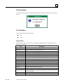
The Tallies Menu
The Tallies menu contains two selections:
View
Clear
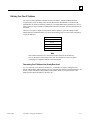
Viewing Tallies
From the Tallies menu, choose View. A list of tallies is displayed. Refer to the table below for a
description of the tallies.
Tally
GFK-1026C
Description
Conn reqs
Number of calls to HCT_connect() routine.
Discon reqs
Number of calls to HCT_disconnect() routine.
Read reqs
Number of calls to HCT_read_req() routine.
Write reqs
Number of calls to HCT _write_req() routine.
Status reqs
Number of calls to HCT_get_status() routine.
CancelMemList reqs
Number of calls to HCT_cancel_mem_list() routine.
EstabMemList reqs
Number of calls to HCT_estab_mem_list() routine.
Cancel reqs
Number of calls to HCT_cancel_request() routine.
Conn confs
Number of sessions successfully established with an HCT_connect () call.
Discon inds
Number of sessions terminated by the remote device.
Data inds
Number of messages transferring data, or responses to our data transfer requests.
Nothing Present
Received a data indication, but no data in the message.
Trans Err
Unable to retrieve data for data indication.
Unknown Resp Code
Host Driver gave unknown error code while we tried to retrieve data.
Bad InvokeID
Received data response for unknown request, or unsolicited message when no user
buffer was available.
Bad HCT Event
Event code from Host Driver was invalid for a data indication.
Unknown SRX ind
Host Driver sent unknown indication.
Chapter 2 Getting Started
2-7
2
Missing Data
Expected message length exceeds length of data actually received.
Clearing Tallies
From the Tallies menu, choose Clear. This sets all tally values to zero.
The Quit Menu
Click the Quit menu to terminate the Host Driver program, free all resources associated with it, and
remove it from memory. This is not necessary during normal operation. However, if the Host
Communications Drivers are not being used and system memory is required for another application,
this is a means of freeing the resources being used by the Host Driver.
If there is currently a connection between a user application above the Host Driver and a remote
device, an attempt to Quit the Host Driver program will result in an error message. The user
application connection must be terminated before the Host Driver may be removed from memory.
Note
Host Drivers operating under Windows for Workgroups limit their users to no
more than 64 simultaneous sessions to remote PLCs. These sessions can be any
combination of TCP and VME sessions.
2-8
Host Drivers and Communications Configuration Software User's Manual – November 1998
GFK-1026C
Chapter
Communication Configuration Utility
3
This chapter describes the Communication Configuration Utility (CCU). The CCU, which runs
under Windows 95 and Windows NT, provides an interactive means of managing the Host Driver
configuration data in the Host Driver configuration file, GEF_CFG.INI.
Configuring Communications
The Communication Configuration Utility allows you to add and edit communication parameters
used by applications to establish connections to PLCs. These parameters are saved in the
configuration file, GEF_CFG.INI.
The communication parameters are divided into four categories.
•
Device (PLC) Configurations. Each device configuration includes a required address to
the target PLC and other optional information. If you are connecting to PLCs over an
Ethernet network, an SNP multidrop network, or through a modem, a device configuration is
needed for each target PLC. See “Device (PLC) Configuration” on page 3-3.
•
PC Port Configurations. Each port configuration includes parameter values for a PC port
(COM1-4 or Ethernet) that will be used by the application initiating the connection. A single
PC port can have more than one port configuration, containing different parameter values.
See “PC Port Configuration” on page 3-5.
•
Global Parameter Configuration. Specifies two timeout parameters, Connect Timeout
and Request Timeout , that can be made to apply globally to all PC ports. See “Global
Parameter Configuration” on page 3-7.
•
Modem Configuration. The CCU provides modem dialing through an SNP connection.
You can create modem configurations that can be included as part of a device or a port
configuration. See “Modem Configuration” on page 3-9.
How Device, PC Port, and Global Parameter Configurations Relate to Each Other
Once a device configuration, a PLC port configuration, a global parameters configuration
(optional), and a modem configuration (optional) have been created and saved, these
configurations can then be used to communicate with a PLC.
To communicate with a PLC, a device configuration and a PC port configuration must be selected.
The means by which they are selected depends upon the application (Host Communications
Toolkit or other application). The device configuration contains the address of the target PLC, and
GFK-1026C
3-1
3
the PC port configuration determines the type of PC port (serial, or Ethernet) and the specific
parameter values to be used for the communication.
Two timeout parameters can be set in the global parameters configuration. These same parameters
can be set in each port configuration. In some programming/configuration software, if no values
exist in the port configuration for these timeout parameters, the values in the global parameters
configuration can be used. HCT applications may handle global parameters differently.
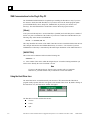
Running the Communication Configuration Utility
When the Communication Configuration Utility is run, you are prompted for a password. To be
able to change the configuration parameters, you must enter the password. The default password is
netutil (all lower case). Passwords may be from 1 to 8 characters long.
To view the CCU without the ability to edit the configuration parameters, you do not need to enter
the password; just click the View Only button.
Saving Your Work
To save changes without leaving the CCU, choose Save from the File menu.
Click the OK button from the Devices, Ports, Global Parameters, or Modems tab to exit the CCU.
Alternatively, you can choose Exit from the File menu. You will be prompted to save your
changes (if you made any). If you click Yes, the changes will be saved and CCU will be exited.
Closing Without Saving Your Work
To exit the CCU without saving your work to the hard disk, choose Exit from the File menu. You
will be prompted to save your changes. If you click No, CCU will be exited, but the changes will
not be saved. Alternatively, you can click the Cancel button in any of the four tabs.
Printing
To print the entire contents of GEF_CFG.INI, choose Print from the File menu.
3-2
Host Drivers and Communications Configuration Software User's Manual – November 1998
GFK-1026C
3
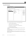
Device (PLC) Configuration
The Devices tab is shown below.
A device configuration identifies the target PLC. A device configuration includes:
•
A name for the configuration (Required).
•
Addresses for the PLC (At least one address required).
•
The model of PLC to be connected (Optional—for documentation only).
•
The Default Port selection (Optional).
•
The Associated Modem selection (Optional)
The Default Port selection specifies the PC port configuration that will normally be used unless
you change it.
The Associated Modem selection specifies the Modem Configuration that contains the required
modem dialing information.
Only one device configuration may be required for some applications. This is the case when
applications on the PC running the CCU will communicate with one or more PLCs only through a
direct serial connection.
GFK-1026C
Chapter 3 Communication Configuration Utility
3-3
3
However, if applications on the PC running the CCU must connect to multiple PLCs over an SNP
multidrop or TCP/IP network, you must create a device configuration for each target PLC. Up to
1000 device configurations of each address type (SNP ID or IP Address) can be created.
Adding a Device Configuration
To add a device configuration:
1.
In the Communication Configuration Utility window, select the Devices tab.
2.
Click the New button. The New Device dialog box appears.
3.
Type the name of the device configuration in the Device Name field. (Required).
4.
Click in the field next to the type of device address (SNP ID or IP Address) you want to
configure and type the device address. A device configuration can contain more than one
device address, but at least one device address is required. (Required)
5.
Click in the Device Model field and choose the appropriate model from the drop-down list.
(Optional)
6.
Click in the Default Port field and choose the name of the port configuration you want to use
as the default for this device configuration. The port configuration must be in the Port Names
list within the Ports tab. (Optional)
7.
Click in the Associated Modem field and choose the name of the modem configuration that
you want to associate with this device. To create a modem configuration, go to the Modems
tab. (Optional)
8.
Click the OK button.
Note
To view detailed technical information about the parameters, click the Help
button within the Add New Device dialog box.
Changing a Device Configuration
To change a device configuration:
1.
In the Communication Configuration Utility window, select the Devices tab.
2.
Select the Device configuration you want to edit from the list of Device Names
3.
Click the Edit button. The Edit Device dialog box appears.
4.
Click in the field next to the parameter you want to change. Some fields require you to choose
from a drop-down list; others require you to type a value. Update all desired parameter values.
(You cannot change the Device Name of an existing device configuration.)
5.
Click the OK button.
Note
To view detailed technical information about the parameters, click the Help
button within the Edit Device dialog box.
3-4
Host Drivers and Communications Configuration Software User's Manual – November 1998
GFK-1026C
3
Deleting a Device Configuration
To delete a device configuration:
1.
In the Communication Configuration Utility window, select the Devices tab.
2.
Select the device configuration you want to delete.
3.
Click the Delete button.
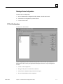
PC Port Configuration
The Ports tab is shown below.
A port configuration provides communications parameter values for a PC port (COM1-4 or
Ethernet) that will be used by the application initiating the connection. A port configuration
includes:
GFK-1026C
•
A name for the configuration.
•
The type of PC port to be used for the connection.
•
Values for the communications parameters for the port.
•
The Associated Modem selection (Optional)
Chapter 3 Communication Configuration Utility
3-5
3
Adding a PC Port Configuration
To add a PC port configuration:
1.
In the Communication Configuration Utility window, select the Ports tab.
2.
Click the New button. The Add New Port dialog box appears.
3.
Type the name of the port configuration in Port Name field.
4.
Click in the Port Type field and choose the appropriate type from the drop-down list. Only the
parameters pertaining to the specified port type will be displayed. Choices are: SNP_SERIAL
Settings, TCPIP_ETH Settings, and TCPIP_SLIP Settings (Serial Line IP).
5.
If you choose not to use the default parameters, click in the field next to the parameter you
want to change. Some fields require you to choose from a drop-down list; others require you
to type a value. Update all desired parameter values.
6.
To edit advanced parameters, click the Advanced>> button.
7.
Click the OK button.
Note
To view detailed technical information about the parameters, click the Help
button within the Add New Port dialog box.
Changing a PC Port Configuration
To change a PC port configuration:
1.
In the Communication Configuration Utility window, select the Ports tab.
2.
Select the port configuration you want to update from the list of Port names.
3.
Click the Edit button. The Edit Port dialog box appears.
4.
Click in the field next to the parameter you want to update. Some fields require you to choose
from a drop-down list; others require you to type a value. Update all desired parameter values.
(You cannot change the Port Name or Port Type of an existing port configuration.)
5.
To edit advanced parameters, click the Advanced>> button.
6.
After you have finished editing, click the OK button.
Note
To view detailed technical information about the parameters, click the Help
button within the Edit Port dialog box.
3-6
Host Drivers and Communications Configuration Software User's Manual – November 1998
GFK-1026C
3
Deleting a PC Port Configuration
To delete a PC port configuration:
1.
In the Communication Configuration Utility window, select the Ports tab.
2.
Select the port configuration you want to delete.
3.
Click the Delete button.
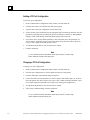
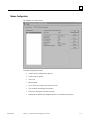
Global Parameter Configuration
The Global Parameters tab is shown below.
The Global Parameters configuration includes settings for Connect Timeout and Request Timeout.
GFK-1026C
•
The Connect Timeout parameter specifies the timeout value when attaching to the target
PLC.
•
The Request Timeout parameter specifies the timeout value on transfer of data.
Chapter 3 Communication Configuration Utility
3-7
3
Configuring Global Timeouts for PC Ports
To configure global timeouts:
1.
In the Communication Configuration Utility window, select the Global Parameters tab.
2.
Click the Edit button.
3.
For each timeout parameter you want to change, click in the field next to the timeout
parameter and type the desired value.
4.
Click the OK button.
Timeout Precedence for Connect Timeout and Request Timeout
Connect Timeout and Request Timeout values can be specified globally or within a port
configuration. The order of precedence is as follows.
3-8
1.
If a value is specified for Connect Timeout or Request Timeout in the active PC port
configuration, this value is used during communications with a PLC.
2.
If no value for Connect Timeout or Request Timeout is specified in the active PC port
configuration, then the global value specified in the Global Parameters configuration is used.
3.
If no value for Connect Timeout or Request Timeout is specified in either the active PC port
configuration or the Global Parameters configuration, the default value is used. The default
value for Connect Timeout is 10500 (10.5 seconds); for Request Timeout the default is 5,000
(5 seconds).
Host Drivers and Communications Configuration Software User's Manual – November 1998
GFK-1026C
3
Modem Configuration
The Modems tab is shown below:
A modem configuration includes
GFK-1026C
•
A name for the configuration (required)
•
Country code (required)
•
Area Code
•
Phone Number
•
Use C and A (use Country Code and Area Code)
•
Your Location (the dialing from location)
•
TAPI Line (description of modem selected)
•
Dialable Phone Number (the telephone number to be dialed by the modem)
Chapter 3 Communication Configuration Utility
3-9
3
Adding a Modem Configuration
To add a modem configuration:
1.
In the CCU window, select the Modems tab.
2.
Click the New button. The Add New Modem dialog box appears.
3.
Edit the parameters in the Add New Modem dialog box and press OK. The dialog box closes
and the modem configuration you added appears in the Modem Names box in the CCU
window.
Editing a Modem Configuration
To edit a modem configuration:
1.
In the CCU window, select the Modems tab.
2.
In the Modem Names box, select the modem configuration that you want to edit.
3.
Click the Edit button. The Edit Modem dialog box appears.
4.
Edit the parameters in the Edit Modem dialog box and press OK. The dialog box closes and
the new parameters for the modem configuration you edited appear in the Selected Modem
Parameter Settings box.
Deleting a Modem Configuration
To delete a modem configuration:
3-10
1.
In the CCU window, select the Modems tab.
2.
In the Modem Names box, select the modem configuration that you want to delete.
3.
Click the Delete button. A confirmation dialog box appears.
4.
Click Yes.
Host Drivers and Communications Configuration Software User's Manual – November 1998
GFK-1026C
3
Sample Device/Port Configurations
There are some device and port configurations shipped with this utility that have a specific use
depending on what software application is using the CCU. These are the configurations,
DEFAULT/COM1-4, ENET, and testplc/port_1.
DEFAULT/COM1-4
"DEFAULT" is the name of the device configuration intended for Direct SNP connection. It is
configured to use an SNP ID of <NULL> indicating a direct connection. It is set to use COM1 at
19,200 baud, odd parity, with 1 stop bit.
Device configuration, DEFAULT, specifies the port configuration, COM1, as the default port. If
COM1 is not available on your system you can change the Default Port value to COM2, COM3, or
COM4.
The port configurations, COM1-COM4, can be specified as the Default Port in device
configurations other than DEFAULT as well.
DEFAULT Device Configuration
The DEFAULT device configuration includes the following parameter values.
SNP ID = <NULL>
Default Port = COM1
COM1 Port Configuration
The COM1 port configuration includes the following parameter values.
Type = SNP_SERIAL
Physical Port = COM1
All other port communications parameters contain default values.
COM2 Port Configuration
The COM2 port configuration includes the following required parameter values.
Type = SNP_SERIAL
Physical Port = COM2
COM3 Port Configuration
The COM3 port configuration includes the following required parameter values.
Type = SNP_SERIAL
Physical Port = COM3
GFK-1026C
Chapter 3 Communication Configuration Utility
3-11
3
COM4 Port Configuration
The COM4 port configuration includes the following required parameter values.
Type = SNP_SERIAL
Physical Port = COM4
ENET
"ENET" is the name of a basic port configuration set up for Ethernet communications.
Type = TCPIP_ETH
testplc/port_1
"testplc" is the name of the device configuration and "port_1" is the name of the port
configuration included with the CCU for use with the Host Communications Toolkit. These
configurations allow you to run the sample programs included with the Host Communications
Toolkit.
testplc Device Configuration
The testplc device configuration includes the following required parameter value.
IP Address = 10.X.X.X (modify this value to match the IP address of your PLC)
port_1 Port Configuration
The port_1 port configuration includes the following required parameter values.
Type = TCPIP_ETH
3-12
Host Drivers and Communications Configuration Software User's Manual – November 1998
GFK-1026C
Chapter
Communication Configuration Library
4
This chapter describes the Communication Configuration Library (CCL). The CCL is a Windows
Dynamic Link Library (DLL) which provides an application programming interface for the user
program to manage the Host Driver configuration data in the Host Driver configuration file,
GEF_CFG.INI. See Appendix A for a detailed description of the contents of the configuration file.
Structures Used With the CCL
This section describes the C/C++ language structures used in communicating with the
Communication Configuration Library (CCL). All structure and mnemonic definitions described
in this section are defined in the CCL.H include file that is supplied on the Host Drivers
installation diskette.
Structures that Apply to Multiple Record Types
This section describes the structures which apply to any record type.
CCL_REC
The CCL_REC structure is a generic structure name that contains each of the possible record
definitions. The format of this structure is as follows:
typedef union {
CCL_PORT_REC
PortRecord;
/* Port Record
CCL_PORT_REC_EX
PortRecordEx; /* Attaches modem record name to Port Record */
CCL_DEV_REC
DeviceRecord;
CCL_DEV_REC_EX
DeviceRecordEx; /* Attaches modem record name to Device Record */
CCL_GP_REC
GlobalParamRecord;
CCL_MODEM_REC
ModemRecord;
/* Device Record
*/
*/
/* Global Parameter Record */
/* Modem Record */
} CCL_REC;
GFK-1026C
4-1
4
SEARCH_KEY_DEF
The SEARCH_KEY_DEF structure is used by the CCL_Get_List routine to allow the caller to
specify parameters to filter out unwanted records. The format of this structure is as follows:
typedef struct {
_TXCHAR KeyWord[2*CCL_MAX_NAME+2];
_TXCHAR Value[2*CCL_MAX_NAME+2];
} SEARCH_KEY_DEF;
Keyword The KeyWord string specifies a valid keyword within the communication
configuration file. Refer to Appendix A for a description of all the valid keywords for each
record type.
Value The Value string specifies a value that goes with the associated keyword string. For
example, if the keyword string is “TYPE” the Value string might be “SNP_SERIAL”.
Port Record Structure
This section describes the CCL_PORT_REC structure, listed on page 4-3 which defines the
contents of a Port record. Note that the first three fields apply to all port record types. All the other
fields apply only to SNP/serial port definitions.
4-2
Host Drivers and Communications Configuration Software User's Manual – November 1998
GFK-1026C
4
CCL_PORT_REC
typedef struct {
_TXCHAR
RecName[2*CCL_MAX_NAME+2 ];
/* Name of port record
unsigned short
PortType;
/* Numeric port type code */
CCL_GP_REC
GlobalParam;
/* Port-specific timeouts */
_TXCHAR
COMport[COM_PORT_LEN+2 ];
/* SNP COM port name
_TXCHAR
ModemDialInfo[2*MODEM_INFO_LEN + 2];
unsigned short
StopBits;
unsigned short
Parity;
unsigned short
BaudRate;
unsigned long
ModemTurn;
unsigned long
SNP_T1;
unsigned long
SNP_T2;
unsigned long
SNP_T3;
unsigned long
SNP_T3p;
unsigned long
SNP_T3pp;
unsigned long
SNP_T4;
unsigned long
SNP_T5;
unsigned long
SNP_T5p;
unsigned long
SNP_T5pp;
unsigned short
AllowMulti;
unsigned short
PCIMChannelId;
_TXCHAR
PCIMPN[PART_NUMBER_LEN + 2];
_TXCHAR
PCIMController[IO_ADDR_LEN +2];
_TXCHAR
PCIMPort[IO_ADDR_LEN + 2];
_TXCHAR
PCIMAddr[MEM_ADDR_LEN + 2];
*/
*/
} CCL_PORT_REC;
typedef struct {
CCL_PORT_REC
PortRecord;
_TXCHAR
ModemRecName[2*CCL_MAX_NAME + 2 ];
} CCL_PORT_REC_EX;
GFK-1026C
Chapter 4 Communication Configuration Library
4-3
4
Device Record Structure
This section describes the CCL_DEV_REC structure, which defines the contents of a Device
record.
CCL_DEV_REC
typedef struct {
_TXCHAR
RecName[ 2*CCL_MAX_NAME + 2 ];
unsigned short
DeviceType;
unsigned short
/* Name of device record*/
PCIMBusAddr;
_TXCHAR
VMEAddr[MAX_VME_ID + 2];
/* VME address
*/
_TXCHAR
IPAddr[MAX_IP_ID + 2];
/* IP address
*/
_TXCHAR
SNPId[2*MAX_SNP_ID + 2];
_TXCHAR
DefaultPort[2*CCL_MAX_NAME + 2 ];
_TXCHAR
DeviceModel[2*MAX_MODEL_NAME + 2];
/* SNP ID
*/
} CCL_DEV_REC;
typedef struct {
CCL_DEV_REC DeviceRecord;
_TXCHAR
ModemRecName[2*CCL_MAX_NAME + 2 ];
} CCL_DEV_REC_EX;
4-4
Host Drivers and Communications Configuration Software User's Manual – November 1998
GFK-1026C
4
Modem Record Structure
This section describes the CCL_MODEM_REC structure, which defines the content of a modem
record.
CCL_MODEM_REC
typedef struct {
_TXCHAR
RecName[ 2*CCL_MAX_NAME + 2 ];
/* Name of modem record */
_TXCHAR
ModemDialInfo[MODEM_INFO_LEN_EX + 2];
_TXCHAR
ModemDispInfo[MODEM_INFO_LEN_EX + 2];
_TXCHAR
ModemCountryName[MODEM_INFO_LEN_EX + 2];
_TXCHAR
ModemAreaCode[MODEM_INFO_LEN_EX + 2];
_TXCHAR
ModemPhoneNumber[MODEM_INFO_LEN_EX + 2];
_TXCHAR
ModemLocation[MODEM_INFO_LEN_EX + 2];
_TXCHAR
ModemTAPILine[MODEM_INFO_LEN_EX + 2];
unsigned short
ModemUsedCountryAndArea;
unsigned short
ModemDeviceID;
} CCL_MODEM_REC;
Global Parameters Structure
This section describes the CCL_GP_REC structure, which defines the Global Parameters record.
CCL_GP_REC
typedef struct {
unsigned long ConnectTimeout;
/* Connect timeout */
unsigned long RequestTimeout;
/* Request timeout */
_TXCHAR Password[ 2*MAX_PW_LEN
+ 2];
/* CCU password */
} CCL_GP_REC;
GFK-1026C
Chapter 4 Communication Configuration Library
4-5
4
CCL Interface Routines for C/C++ Applications
This section describes the C/C++ calling sequence of each of the interface routines of the CCL.
CCL_Add_Record
This routine is called to add a new record to the configuration file.
FUNCTION_TYPE CCL_Add_Record(unsigned short
RecType,
CCL_REC PTR_TYPE RecInfo);
RecType A code indicating the record type (device, port, or global parameters) being added.
The following mnemonics are the only valid record types:
PORT_REC_TYPE
DEV_REC_TYPE
GP_REC_TYPE
MODEM_REC_TYPE
Port record
Device record
Global Parameters
Modem record
RecInfo The data which defines this record.
Note
For an unused string type field, you must set the first byte of the string to '\0'
(the null character). For an unused numerical type field, you must set it to the
value FIELD_NOT_ASSIGNED which is defined as 0xffffffff.
Note
In the case of adding Device Names, you can optionally add one field of a record
by assigning one of the following values to the Device Type field of RecInfo
parameter.
SNP_SERIAL:
TCPIP_ETH, TCPIP_SLIP:
VME_PORT:
ALL_DEV_TYPE:
Adds the field with keyword SNP_ID
Adds the field with keyword IP_ADDR
Adds the field with keyword DEST_ADDR
Adds all fields which are not NULL strings in the
RecInfo parameter
Return Codes
If the request was executed successfully, the value CCL_OK (0) will be returned. Otherwise the
record was not inserted and one of the following error codes will be returned.
4-6
Host Drivers and Communications Configuration Software User's Manual – November 1998
GFK-1026C
4
Return Code
Value
(dec)
Value
(hex)
Interpretation
CCL_BAD_RECTYPE
-1
FFFF FFFF
The RecType parameter contains an unknown record
type code.
CCL_NULL_PTR
-2
FFFF FFFE
The RecInfo parameter contains a NULL pointer.
CCL_BAD_DEVTYPE
-3
FFFF FFFD
The DeviceType field of the CCL_DEV_REC
structure is out of range.
CCL_DUPLICATE
-4
FFFF FFFC
The RecName field of the CCL_PORT_REC,
CCL_MODEM_REC, or CCL_DEV_REC structure
contains a name which matches an existing record.
CCL_NOT_SUPPORTED
-5
FFFF FFFB
The requested record or subfield is not supported.
CCL_RESOURCE
-6
FFFF FFFA
Could not allocate buffer
CCL_BAD_SNPID
-7
FFFF FFF9
The SNPId field of the CCL_DEV_REC structure is
invalid.
CCL_BAD_NAME
-8
FFFF FFF8
The RecName field of the CCL_PORT_REC,
CCL_MODEM_REC, CCL_DEV_REC structure
contains a name that is not valid.
CCL_BAD_IPADDR
-9
FFFF FFF7
The IPADDR field of the CCL_DEV_REC structure
is invalid.
CCL_BAD_VMEADDR
-10
FFFF FFF6
The VMEADDR field of the CCL_DEV_REC
structure is invalid.
CCL_BAD_PORTTYPE
-11
FFFF FFF5
The value of the PortType field of the
CCL_PORT_REC structure is out of range.
CCL_BAD_COMPORT
-12
FFFF FFF4
The string in the COMport field of the
CCL_PORT_REC structure is not “COM1”,
“COM2”, “COM3”, or “COM4”.
CCL_BAD_DEFAULTPORT
-13
FFFF FFF3
The DefaultPort field of the CCL_DEV_REC
structure contains an invalid port name.
CCL_BAD_SEARCHKEY
-14
FFFF FFF2
Search key specified is invalid.
CCL_NOT_FOUND
-15
FFFF FFF1
Requested record is not found.
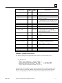
CCL_REQ_FAIL
-99
FFFF FF9D
CCL failed to access the configuration file.
Example #1 - Defining a Device Record
The following example code segment shows how to define a new Device Name record.
CCL_REC MyRecord;
memset( (char *)MyRecord, 0, sizeof( CCL_REC ) );
strcpy( MyRecord.DeviceRecord.RecName, “FRED” );
// Set Device Name
MyRecord.DeviceRecord.DeviceType = TCPIP_ETH;
// Port type used
strcpy( MyRecord.DeviceRecord.IPAddr,"10.X.X.X");
Note that in the above example, the memset call sets all bytes of the CCL_REC structure to zero.
Because we do not overwrite the VMEAdr, SNPId, DefaultPort, DeviceModel fields with other
data, the corresponding keywords for those fields will not be defined for this Device record.
GFK-1026C
Chapter 4 Communication Configuration Library
4-7
4
Example #2 - Defining a Port Record
The following example code segment shows how to define a new Port Name record.
CCL_REC MyRecord;
memset( (char *)MyRecord, 0xFF, sizeof( CCL_REC ) );
strcpy( MyRecord.PortRecord.RecName, “HORTON” );
// Set Port Name
MyRecord.PortRecord.PortType = SNP_SERIAL;
// Port type used
strcpy( MyRecord.PortRecord.COMPort, “COM2” );
// Set COM port
MyRecord.PortRecord.ModemDialInfo[0] = '\0';
Note that in the above example, the memset call sets all bytes of the CCL_REC structure to
indicate FIELD_NOT_ASSIGNED for the numerical fields; therefore, it is important to initialize
MyRecord.PortRecord.Modem Dial Info[0] to '\0' because it is an unused string type field. Because
we do not overwrite the other fields with new data, the corresponding keywords for those fields
will not be defined for this Port record.
Example #3 - Defining Global Parameters
The following example code segment shows how to define a new Global Parameters record.
CCL_REC MyRecord;
memset( (char *)MyRecord, 0xFF, sizeof( CCL_REC ) );
MyRecord.GlobalParamRecord.ConnectTimeout = 8500; // Connect timeout = 8.5s
MyRecord.GlobalParamRecord.RequestTimeout = 750;
// Request timeout = 750ms
If the proposed Connect Timeout or Request Timeout value is greater than TIMEOUT_MAX,
TIMEOUT_MAX will be stored. Likewise, if the proposed value is less than TIMEOUT_MIN,
TIMEOUT_MIN will be stored.
4-8
Host Drivers and Communications Configuration Software User's Manual – November 1998
GFK-1026C
4
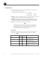
CCL_Delete_Record
This routine is called to remove a record from the configuration file.
FUNCTION_TYPE CCL_Delete_Record(unsigned short
RecType,
unsigned short
DeviceType,
_TXCHAR PTR_TYPE RecName);
RecType A numeric code indicating what type of record is being deleted. The valid values are
the same as for the RecType parameter of the CCL_Add_Record() routine.
DeviceType A numeric code indicating which field of the Device Name record is to be
deleted. This parameter is ignored if the RecType parameter is not DEV_REC_TYPE.
RecName The record name. For a device record, this is the Device Name. (For a modem
record, this is the modem name.) For a port record, this is the Port Name. For Global
Parameters, this parameter is ignored and the “Global_Parameters” section is removed from
the configuration file.
Note
In the case of deleting Device Name records, you can optionally delete one field
or the whole record by assigning one of the following values to the DeviceType
parameter.
SNP_SERIAL
TCPIP_ETH, TCPIP_SLIP
VME_PORT
ALL_DEV_TYPE
Deletes the field with keyword SNP_ID
Deletes the field with keyword IP_ADDR
Deletes the field with keyword DEST_ADDR
Deletes the whole record
Return Codes
If the request was executed successfully, the value CCL_OK will be returned. Otherwise the
record or field was not deleted and one of the following error codes will be returned.
Return Code
GFK-1026C
Value
(dec)
Value
(hex)
CCL_BAD_RECTYPE
-1
FFFF FFFF
The RecType parameter contains an
unknown record type code.
CCL_NULL_PTR
-2
FFFF FFFE
The RecName parameter contains a NULL
pointer.
CCL_NOT_FOUND
-15
FFFF FFF1
The specified record name (RecName field)
does not match a record name currently in
the configuration file.
CCL_REQ_FAIL
-99
FFFF FF9D
CCL failed to access the configuration file.
Chapter 4 Communication Configuration Library
Interpretation
4-9
4
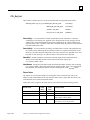
CCL_Get_Record
This routine is called to retrieve a record from the configuration file. The caller specifies the
record name and type as search parameters.
FUNCTION_TYPE CCL_Get_Record(unsigned short
RecType,
_TXCHAR PTR_TYPE
RecName,
CCL_REC PTR_TYPE
RecBuf);
RecType A numeric code indicating what type of record is being fetched. The valid values are
the same as for the RecType parameter of the CCL_Add_Record() routine.
RecName The record name. For a device record, this is the Device Name. (For a modem
record, this is the modem name.) For a port record, this is the Port Name. For Global
Parameters, this parameter is ignored and the “Global_Parameters” section is retrieved.
RecBuf A pointer to a buffer which will hold the retrieved record.
Note
If a string type entry is missing in the configuration file, the corresponding field
in the RecBuf will contain a NULL string. If a numerical type entry is missing
in the configuration file, the corresponding field in the RecBuf will contain a
field stored with the value FIELD_NOT_ASSIGNED.
Return Codes
If the request was executed successfully, the value CCL_OK will be returned. Otherwise the
record or field was not retrieved and one of the following error codes will be returned.
Return Code
4-10
Value
(dec)
Value
(hex)
Interpretation
CCL_BAD_RECTYPE
-1
FFFF FFFF
The RecType parameter contains an
unknown record type code.
CCL_NULL_PTR
-2
FFFF FFFE
The RecName or RecInfo parameter
contains a NULL pointer.
CCL_NOT_FOUND
-15
FFFF FFF1
The specified record name (RecName
parameter) does not match a record name
currently in the configuration file.
CCL_BAD_PORTTYPE
-11
FFFF FFF5
Port type value in the configuration file is
invalid.
Host Drivers and Communications Configuration Software User's Manual – November 1998
GFK-1026C
4
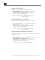
CCL_Get_List
This routine is called to retrieve a list of record names that meet specified search criteria.
FUNCTION_TYPE CCL_Get_List(SEARCH_KEY_DEF PTR_TYPE
SearchKey1,
SEARCH_KEY_DEF PTR_TYPE
SearchKey2,
_TXCHAR
NameBuf,
PTR_TYPE
unsigned short PTR_TYPE
NumNames);
SearchKey1 A set of parameters to filter out unwanted records. This filter is a structure
containing a keyword string (see Appendix A for valid keywords for each port type) and an
optional value associated with that keyword in the configuration file. The keyword string is
required, but the value is optional. If the value is omitted, merely the presence of the specified
keyword includes that record.
SearchKey2 A set of parameters providing a secondary filter to records. This parameter may
be a NULL pointer, indicating only the primary search key is required. If this pointer is nonNULL, the secondary keyword string must be one of the valid ones (see Appendix A for valid
keywords for each port type). As with SearchKey1, the keyword value is optional.
NameBuf A buffer to hold the record names (variable length, NULL-terminated ASCII
strings) of all records that meet the search criteria. Each name requires up to
CCL_MAX_NAME+1 bytes.
NumNames Initially this field must contain the maximum number of names (each occupying
CCL_MAX_NAME+1 bytes) that will fit into the NameBuf buffer. Upon a successful search,
this parameter will contain the number of names actually present in the NameBuf buffer.
Return Codes
The request was executed successfully if a non-negative value is returned. This value is the
number of names found that meet the search criteria. If this value is larger than NumNames, the
NameBuf buffer is too small to hold all the names.
If the return value is negative, the search was not successful for one of the following reasons:
Value
(dec)
Value
(hex)
CCL_RESOURCE
-6
FFFF FFFA
CCL_REQ_FAIL
-99
FFFF FF9D
CCL failed to access the configuration file.
CCL_NULL_PTR
-2
FFFF FFFE
The SearchKey1, NameBuf, or NumNames
field contains a NULL pointer.
CCL_BAD_SEARCHKEY
-14
FFFF FFF2
The keyword string in SearchKey1 or
SearchKey2 is not a valid keyword.
Return Code
GFK-1026C
Chapter 4 Communication Configuration Library
Interpretation
A buffer allocation failed.
4-11
4
Example #1 - Get All Port Names
This shows how to retrieve records for all Port Name definitions.
#define
MAX_NAMES_ALLOWED
30
// User-specified max name count
SEARCH_KEY_DEF key1 = { {“TYPE”}, {“\0”} };
unsigned char NameBuf[ MAX_NAMES_ALLOWED * (CCL_MAX_NAME+1) ];
unsigned int NumNames = MAX_NAMES_ALLOWED;
response = CCL_Get_List(&key1, (SEARCH_KEY_DEF far *)NULL,
NameBuf, &NumNames );
Example #2 - Get All Port Records for Port COM1
This shows how to retrieve Port Name records for all ports that use “COM1”.
#define
MAX_NAMES_ALLOWED
10
// User-specified max name count
SEARCH_KEY_DEF key1 = { {“PORT”}, {“COM1”} };
unsigned char NameBuf[ MAX_NAMES_ALLOWED * (CCL_MAX_NAME+1) ];
unsigned int NumNames = MAX_NAMES_ALLOWED;
response = CCL_Get_List(&key1, (SEARCH_KEY_DEF far *)NULL,
NameBuf, &NumNames );
Example #3 - Get All 90-70 CPUs Reachable Through Ethernet
This shows how to retrieve Device Name records for all Series 90-70 PLCs that can be accessed
via TCP/IP over Ethernet.
#define
MAX_NAMES_ALLOWED
25
// User-specified max name count
SEARCH_KEY_DEF key1 = { {“IP_ADDR”}, {“\0”} };
SEARCH_KEY_DEF key2 = { {“DEVICE_MODEL”}, {“9070”} };
unsigned char NameBuf[ MAX_NAMES_ALLOWED * (CCL_MAX_NAME+1) ];
unsigned int NumNames = MAX_NAMES_ALLOWED;
response = CCL_Get_List(&key1, &key2, NameBuf, &NumNames );
4-12
Host Drivers and Communications Configuration Software User's Manual – November 1998
GFK-1026C
4
CCL_Get_Version
This routine is called to return the revision level of the CCL software. This revision string is a
NULL-terminated ASCII string that may be printed by the calling program.
FUNCTION_TYPE CCL_Get_Version(_TXCHAR PTR_TYPE
ReturnBuf);
Vstring A pointer to a buffer of at least VERSION_STRING_LEN bytes in length.
Return Codes
This request returns the value CCL_OK if the operation was successful. If a NULL pointer is
passed in the Vstring field, no copying is performed and the value CCL_NULL_PTR will be
returned.
GFK-1026C
Chapter 4 Communication Configuration Library
4-13
Appendix Configuration File Description
A
This appendix describes the contents of the configuration file, GEF_CFG.INI. In the Windows
environment, this file normally resides in the Windows root directory (such as \WINDOWS). In
other environments, this file is expected to be in the same directory as your HCT executable.
On Windows 95 or Windows NT platforms, use the Communication Configuration Utility (CCU)
to edit this file. On platforms other than Windows 95 or Windows NT, you must edit this file
directly using an ASCII text editor.
General Record Description for the Configuration File
The configuration file is composed of a series of port, device, and modem records mixed in any
order. It can be determined whether a record is for a port, device, or modem based upon the fields
within the record. In addition, there is a global parameters section.
Generic Format
The generic format of a record is ...
[Record-Name]
<keyword#1> = <data>
<keyword#2> = <data>
. . .
<keyword#n> = <data>
[Record-Name]
<keyword#1> = <data>
<keyword#2> = <data>
. . .
<keyword#n> = <data>
. . . "where "Record-Name" could be a device name, a port name, a modem name,
or "Global_Parameters".
GFK-1026C
A-1
A
Record Formation Rules
The following rules apply to all records.
The record name (device name or port name) is enclosed within square brackets
("[" and "]"). The left bracket ("[") must be the first character on that line.
The record name is the only data on that line.
Immediately following the line with the record name are a series of lines with a keyword,
followed by an equals sign ("="), followed by the data appropriate for that keyword.
The order of the keyword=data fields is not important.
Port Records
This section describes the record format for ports. A port is a description of a physical means of
accessing remote devices.
A port record contains the following information:
1.
An ASCII port name. (required)
2.
Underlying communications type. (required)
3.
Port-specific timeout parameters. (optional)
4.
Port communications parameters. (applies only to SNP)
5.
Modem record name. (optional)
Port Name
The Port Name is the primary piece of information that a Host Driver user specifies to indicate
over which port it wishes to communicate. The Port Name has the following characteristics:
ASCII character string, NULL-terminated.
String length is from one (1) to thirty-two (32) characters.
Uses any printable ASCII character (hexadecimal codes 0x20 through 0x7E), excluding a
right square bracket ("]").
The first character must be a letter ('A' through 'Z' or 'a' through 'z').
Port Names are not case sensitive.
Port Names must be unique among all record names in the configuration file.
There may be multiple port records for the same physical port on the local device. In this way you
can define different communications characteristics to the same physical port.
A-2
Host Drivers and Communications Configuration Software User's Manual – November 1998
GFK-1026C
A
Communications Type
This field contains a string indicating what type of communications is available through this port.
The TYPE keyword is used to specify one of the following port types.
Mnemonic
Communications Type
TCPIP_ETH
TCP/IP protocol over an Ethernet Local Area Network
TCPIP_SLIP
Serial Line Internet Protocol (SLIP) over an Ethernet LAN
SNP_SERIAL
SNP protocol over a serial line
VME_PORT
Full VME mailbox connection
Note
The SNP port type is available only on Windows platforms. The VME port type
is only available on a Plug & Play PC.
Port-Specific Timeout Parameters
You can specify timeout parameters for HCT_connect() requests through this port, data transfer
requests through this port, or both. See the Timeout Precedence section below for more
information about what timeout values are used if no values are specified in this port record.
The CONNECT_TIMEOUT keyword specifies the value for the timeout on HCT_connect()
requests. The REQUEST_TIMEOUT keyword specifies the value for the timeout on data transfer
requests.
Port Communications Parameters
The only port type that has communications parameters is SNP_SERIAL. The parameters with
keywords SNP_T3, SNP_T3P, SNP_T2PP, STOPBITS, PARITY, BAUDRATE, SNP_T1,
SNP_T2, SNP_T4, SNP_T5, SNP_T5P, SNP_T5PP, MULTISESS, MODEM_RECORDNAME,
and MODEM_TURN will be added to the record only if non-default values are assigned to them.
Port Record Keywords
This section defines the keywords that are recognized as valid for Port Records. The following
table shows what keywords apply to each port type. A value of “R” means that parameter is
required for that port type. A value of “O” means that parameter is optional for that port type. No
letter indicates that this keyword is not valid for that port type.
GFK-1026C
Appendix A Configuration File Description
A-3
A
Keyword
TCPIP_ETH
TCPIP_SLIP
BAUDRATE
CONNECT_TIMEOUT
SNP_SERIAL
O
O
O
MODEM_RECORDNAME
O
O/R*
MULTISESS
O
PARITY
O
PORT
R
O
O
O
SNP_T1
O
SNP_T2
O
SNP_T3
R
SNP_T3P
R
SNP_T3PP
R
SNP_T4
O
SNP_T5
O
SNP_T5P
O
SNP_T5PP
O
STOPBITS
TYPE
O
O
MODEM_TURN
REQUEST_TIMEOUT
VME_PORT
O
O
R
R
R
R
* The MODEM_TURN parameter must be present if a modem is used and must not be present if a
modem is not used.
The port record keywords are listed in alphabetical order.
BAUDRATE Keyword
This keyword is optional for ports with a TYPE of SNP_SERIAL. It is not allowed for any other
port type.
This keyword specifies the baud rate to be used on this serial COM port. The possible values for
this keyword are (expressed in bits per second):
•
300 (300 bps)
•
600 (600 bps)
•
1200 (1,200 bps)
•
2400 (2,400 bps)
•
4800 (4,800 bps)
•
9600 (9,600 bps)
•
19200 (19,200 bps)
If this keyword is omitted, a baud rate of 19,200 bps is used.
A-4
Host Drivers and Communications Configuration Software User's Manual – November 1998
GFK-1026C
A
CONNECT_TIMEOUT Keyword
This keyword specifies how long the Host Communications Toolkit (HCT) should wait on a
blocking HCT_connect() call before declaring a timeout. As with the CONNECT_TIMEOUT
parameter in the Global Parameters section of the configuration file, the value for this parameter
ranges from 50 (50 milliseconds) to 63,000 (63 seconds). See the Timeout Precedence section
below for more information about what timeout values are used if this field is not present in the
port record.
This keyword applies to any port, regardless of the port TYPE.
MODEM_RECORDNAME
This keyword defines the modem record name to be used by the port . It is optional for ports with
a TYPE of SNP_SERIAL.
Note
This value is only valid on Win32 platforms.
MODEM_TURN Keyword
This keyword is optional for ports with a TYPE of SNP_SERIAL. It is not allowed for any other
port type.
This keyword specifies the modem turnaround time value. This is the time required for the
modem to start data transmission after receiving the transmit request from the target device.
It can range from 0 to 255 counts, where one count is 10 milliseconds (0.01 seconds). If a modem
is being used through this COM port, this field must be present and must have a non-zero value. If
a modem is not being used, then either this keyword should not be used or the value specified
must be zero. If this keyword is omitted, a value of zero (0) is assumed.
MULTISESS Keyword
Specifies whether to allow multiple sessions through the same PC port with the PLC CPU. The
possible values are YES or NO. The default value is YES.
Note
The only reason to set this value to NO is to connect to Serial Communications
Modules, IC697CMM711 and IC693CMM311. These modules support only a
single session.
GFK-1026C
Appendix A Configuration File Description
A-5
A
PARITY Keyword
This keyword is optional for ports with a TYPE of SNP_SERIAL. It is not allowed for any other
port type.
This keyword specifies the parity sense to be assumed for this serial COM port. The possible
values for this keyword are ODD (odd parity), EVEN (even parity), or NONE (no parity). If this
keyword is omitted, odd parity is used.
PORT Keyword
This keyword is required for ports with a TYPE of SNP_SERIAL. It is not allowed for any other
port type.
This keyword specifies what local COM port is to be used to communicate with the target device.
The possible values for this keyword are COM1, COM2, COM3 or COM4.
REQUEST_TIMEOUT Keyword
This keyword specifies how long the Host Communications Toolkit (HCT) should wait on a
blocking data transfer before declaring a timeout. As with the REQUEST_TIMEOUT parameter
in the Global Parameters section of the configuration file, the value for this parameter ranges from
50 (50 milliseconds) to 63,000 (63 seconds). See the Timeout Precedence section below for more
information about what timeout values are used if this field is not present in the port record.
This keyword applies to any port, regardless of the port TYPE.
SNP_T1 Keyword
This keyword is optional for ports with a TYPE of SNP_SERIAL. It is not allowed for any other
port type.
This keyword specifies the SNP T1 timer. This is the Minimum Turn-Around Time, and it is
specified in units of milliseconds.
If this parameter is omitted, the default value of 10 (milliseconds) is used.
SNP_T2 Keyword
This keyword is optional for ports with a TYPE of SNP_SERIAL. It is not allowed for any other
port type.
This keyword specifies the SNP T2 timer. This is the Acknowledgment Timeout, and it is
specified in units of milliseconds.
If this parameter is omitted, the default value of 3,000 (3 seconds) is used.
A-6
Host Drivers and Communications Configuration Software User's Manual – November 1998
GFK-1026C
A
SNP_T3 Keyword
This keyword is required for ports with a TYPE of SNP_SERIAL. It is not allowed for any other
port type.
This keyword specifies the SNP T3 timer. This is the Link Keep-Alive Time, and it is specified in
units of milliseconds.
If this parameter is omitted, the default value of 10,000 (10 seconds) is used. A value of zero (0)
indicates this timeout has been disabled.
SNP_T3P Keyword
This keyword is required for ports with a TYPE of SNP_SERIAL. It is not allowed for any other
port type.
This keyword specifies the SNP T3’ timer. This is the Link Idle Timeout, and it is specified in
units of milliseconds.
If this parameter is omitted, the default value of 10,100 (10.1 seconds) is used. Its value should be
at least 80 character times (about 100 milliseconds at 9600 bps) more than SNP_T3. A value of
zero (0) indicates this timeout has been disabled.
SNP_T3PP Keyword
This keyword is required for ports with a TYPE of SNP_SERIAL. It is not allowed for any other
port type.
This keyword specifies the SNP T3’’ timer. This is the Attach Link Idle Timeout, and it is
specified in units of milliseconds.
If this parameter is omitted, the default value of 65,000 (65 seconds) is used. Its value should be
at least 54,900 (54.9 seconds) more than SNP_T3P. A value of zero (0) indicates this timeout has
been disabled.
SNP_T4 Keyword
This keyword is optional for ports with a TYPE of SNP_SERIAL. It is not allowed for any other
port type.
This keyword specifies the SNP T4 timer. This is the Break Processing Time, and it is specified in
units of milliseconds.
If this parameter is omitted, the default value of 100 (milliseconds) is used when the modem
turnaround time is zero (see the MODEM_TURN keyword) or a default value of 600
(milliseconds) is used when the modem turnaround time is non-zero.
GFK-1026C
Appendix A Configuration File Description
A-7
A
SNP_T5 Keyword
This keyword is optional for ports with a TYPE of SNP_SERIAL. It is not allowed for any other
port type.
This keyword specifies the SNP T5 timer. This is the Maximum Processing Time, and it is
specified in units of milliseconds.
If this parameter is omitted, the default value of 10,000 (10 seconds) is used.
SNP_T5P Keyword
This keyword is optional for ports with a TYPE of SNP_SERIAL. It is not allowed for any other
port type.
This keyword specifies the SNP T5’ timer. This is the Processing Timeout, and it is specified in
units of milliseconds.
If this parameter is omitted, the default value of 10,100 (10.1 seconds) is used. Its value should be
at least 80 character times (about 100 milliseconds) more than SNP_T5.
SNP_T5PP Keyword
This keyword is optional for ports with a TYPE of SNP_SERIAL. It is not allowed for any other
port type.
This keyword specifies the SNP T5’’ timer. This is the Buffer Message Timeout, and it is
specified in units of milliseconds.
If this parameter is omitted, the default value of 10,200 (10.2 seconds) is used. Its value should be
at least the transmission delay (about 100 milliseconds) more than SNP_T5P.
STOPBITS Keyword
This keyword is optional for ports with a TYPE of SNP_SERIAL. It is not allowed for any other
port type.
This keyword specifies the number of stop bits to be used. The possible values are 1 (one stop bit)
or 2 (two stop bits). If this keyword is omitted, one (1) stop bit is used.
TYPE Keyword
This keyword is the only required keyword for all Port Records. It defines which communications
type is to be used for this port. The data portion is one of the mnemonics listed above in the
Communications Type section.
A-8
Host Drivers and Communications Configuration Software User's Manual – November 1998
GFK-1026C
A
Sample Port Record Entries
The following represents sample entries in the configuration file. The lines that begin with a
semicolon (";") are comments placed there to help the reader.
;
This is the minimum specification for an SNP port without a modem
[SNP_PORT_WITHOUT_MODEM]
PORT=COM1
TYPE=SNP_SERIAL
CONNECT_TIMEOUT=10000
REQUEST_TIMEOUT=16000
;
This is the minimum specification for an SNP port with a modem
[SNP_PORT_WITH_MODEM]
PORT=COM1
TYPE=SNP_SERIAL
SNP_T5PP=10250
CONNECT_TIMEOUT=10000
REQUEST_TIMEOUT=16000
MODEM_RECORDNAME=modem1
;
This defines a TCP/IP port.
[TCP_PORT]
TYPE=TCPIP_ETH
;
This defines a SLIP port.
[SLIP_PORT]
TYPE=TCPIP_SLIP
;
This defines a VME port.
[VME_PORT]
TYPE=VME_PORT
GFK-1026C
Appendix A Configuration File Description
A-9
A
Device Records
This section describes the record format for remote devices. A device is generally thought of as a
Series 90 PLC. However, the user application may choose to talk to an application on another host
machine that also uses a Host Driver.
A Device Record contains the following information:
1. An ASCII device name. [required]
2.
Addressing information. [required]
3.
Default port name. [optional]
4.
Device model information. [optional]
5.
Modem record name. (optional)
Device Name
The device name is the primary piece of information that Host Driver users specify to indicate to
which remote device it wishes to communicate. The device name has the following characteristics:
ASCII character string, NULL-terminated.
String length is from one (1) to thirty-two (32) characters.
Uses any printable ASCII character (hexadecimal codes 0x20 through 0x7E), excluding a
right square bracket ("]").
The first character must be a letter ('A' through 'Z' or 'a' through 'z').
Device Names are not case sensitive.
Device Names must be unique among all record names in the configuration file.
There may be only one record for a given device name.
Addressing Information
This field contains information that identifies the remote target device address.
Ethernet LAN Addressing (TCP/IP or SLIP)
If the target device is available from a Local Area Network (LAN), the addressing information is
the network address. This is an Internet Protocol (IP) address, which has four subfields separated
by periods. An example IP address is 10.X.X.X.
The IP_ADDR keyword is used to specify this address.
A-10
Host Drivers and Communications Configuration Software User's Manual – November 1998
GFK-1026C
A
VMEbus Addressing
This address is currently fixed at 10E00000. No other value is permitted.
The DEST_ADDR keyword is used to specify this value.
SNP/Serial Addressing
If the target device is being accessed over a point-to-point serial connection, use the special value
of <NULL> to denote a null SNP ID. If the target device is being accessed over a multidrop serial
connection, a non-NULL SNP ID is required.
The SNP_ID keyword is used to specify this identifying value.
Default Port Name
If a single device has multiple ports that can be used to gain access to it, you may wish to specify a
preference for the Host Drivers using one particular port. By using the DEFAULT_PORT
keyword, you can specify the Port Name of the preferred port to use to access this target device.
Note that when connecting to this device, the caller may specify a Port Name of “DEFAULT” (all
upper case) in the HCT_connect() call to tell the Host Drivers to use the specific port named in the
device record. This also allows you to change the preferred path without changing the application
source code.
If the port name specified by the DEFAULT_PORT keyword does not exist in the Host Drivers
configuration file, an error will be returned if the application attempts to connect to this device
using a Port Name of “DEFAULT”. Likewise, if the addressing information for this device does
not match the addressing information for the default port (for example, an IP address is given, but
the port is for VME communications), an error will be returned if the application attempts to
connect to this device using a Port Name of “DEFAULT”.
Device Model Information
The device model field is an optional field provided to identify target PLCs by the CPU model
type. The only valid values for the character string field are:
•
"9070"
- Series 90-70 PLC
•
"9030"
- Series 90-30 PLC
•
"9020"
- Series 90-20 PLC
•
"Micro" - Series 90 Micro PLC
This field is useful for searching the configuration database with CCL for a group of target
devices. Use or non-use of this field does not affect operation of the Host Communications
software.
GFK-1026C
Appendix A Configuration File Description
A-11
A
Device Record Keywords
This section defines the keywords that are recognized as valid for device records. The keywords
are listed in alphabetical order.
DEFAULT_PORT Keyword
This keyword specifies the port name of an existing port record within the Host Drivers
configuration file that should be used if the user application attempts to connect to this device with
a port name of “DEFAULT”.
Note
If a valid port record is created with a port name of “DEFAULT,” this port
record will never be used.
The data portion of this field must have a valid port name.
DEST_ADDR Keyword
This keyword specifies the VME mailbox destination address of the target device. This keyword is
required if a port name using the VME_PORT port type is specified in the DEFAULT_PORT
field.
Currently, the data portion of this field is required to be 10E00000.
IP_ADDR Keyword
This keyword specifies the Internet Protocol (IP) address of the target device. This keyword is
required if a port name using either the TCPIP_ETH or TCPIP_SLIP port type is specified.
The data portion of this field must have four subfields separated by periods and with no spaces
(for example, 10.X.X.X). There is no default value.
SNP_ID Keyword
This keyword specifies the SNP ID of the target device. This keyword is only used if a port name
using the SNP_SERIAL port type is specified in the DEFAULT_PORT field.
The data portion of this field must have either an SNP ID in it or the value <NULL>.
A valid SNP ID is a string of one to seven ASCII characters from the following:
•
'A' through 'Z', 'a' through 'z' (not case sensitive)
•
'O' through '9'
•
any other printable ASCII character
The first character must be alphabetic.
For direct connection to a PLC (not multidrop), use the special value of <NULL> to denote a null
SNP ID.
A-12
Host Drivers and Communications Configuration Software User's Manual – November 1998
GFK-1026C
A
MODEM_RECORD_NAME
This keyword defines the modem record name to be used by the device.
Sample Device Record Database Entry
The following represents sample entries in the configuration file. The lines that begin with a
semicolon (";") are comments placed there to help the reader.
;
This device may only be accessed via TCP/IP (SLIP or Ethernet)
[dev_A]
IP_ADDR = 10.X.X.X
;
This device may only be accessed via VMEbus
[TargetApplication]
DEST_ADDR=10E00000
;
This device may only be accessed via point-to-point SNP
[SerialPLC14]
SNP_ID = <NULL>
;
This device may be accessed via multidrop SNP
[SerialPLC15]
SNP_ID=A234567
;
This device may be accessed via TCP/IP, VMEbus, or SNP multidrop
[PLCnumber53]
IP_ADDR = 10.X.X.X
DEST_ADDR=10E00000
SNP_ID=MARYLOU
DEFAULT_PORT=TargetApplication
GFK-1026C
Appendix A Configuration File Description
; Preferred port is VME
A-13
A
Modem Records
A modem record contains dialing information and is included as part of a device or a port record.
A record name (modem name) is required. The maximum length of the modem name is 32
characters. No blanks are allowed. Modem name is not case-sensitive.
Modem Name
The Modem Name is the primary piece of information that a Host Driver user specifies to indicate
the modem device over which it wishes to communicate. The Modem Name has the following
characteristics:
ASCII character string, NULL-terminated.
String length is from one (1) to thirty-two (32) characters.
Uses any printable ASCII character (hexadecimal codes 0x20 through 0x7E), excluding a
right square bracket ("]").
The first character must be a letter ('A' through 'Z' or 'a' through 'z').
Modem Names are not case sensitive.
Modem Names must be unique among all record names in the configuration file.
There may be multiple records for the same physical modem. In this way you can define different
communications characteristics for the same physical modem.
Modem Record Keywords
This section defines the keywords that are recognized as valid for modem records. The keywords
are listed in alphabetical order.
MODEM_DIAL
The dialable phone number. (This telephone number format contains the numbers exactly as they
will be dialed.)
MODEM_DISP
The phone number in displayable format.
MODEM_COUNTRYNAME
Country name is required if Use C and A is set to YES. For selections, see the modem properties
in the Windows settings.
A-14
Host Drivers and Communications Configuration Software User's Manual – November 1998
GFK-1026C
A
MODEM_AREACODE
Area code of the modem (dialing from location). This is required if Use C and A is set to YES.
MODEM_PHONENO
Phone number of the modem (dialing from location). This keyword is required.
MODEM_LOCATION
Optional keyword identifies the dialing from location.
MODEM_TAPILINE
Identifies the TAPI driver for the modem that is connected to the COM port used with the modem
record.
MODEM_USEDCANDA
Use country and area code. Value is YES or NO. If this keyword is YES, the
MODEM_COUNTRYNAME and MODEM_AREACODE keywords are required.
MODEM_DEVICEID
MODEM_DEVICEID is the 0 based index of the device in the list of modem devices in the
system. The device itself is identified by MODEM_TAPILINE. In the CCU Edit/New Modem
dialog box, there is a TAPI Line drop-down list box. The position of the selected modem device in
this list determines the MODEM_DEVICEID.
GFK-1026C
Appendix A Configuration File Description
A-15
A
Global Parameters
In addition to being able to configure device names and port names, you can also control timeout
lengths for Host Communications Toolkit requests. This is accomplished by reserving a special
record name, “Global_Parameters”, in the configuration file.
The purpose in having timeout parameters available to users through the configuration file is to
allow user control over how long the HCT application waits for certain events. For some timecritical operations, the default timeout parameters may not be sufficient. For other operations you
may choose either to use the HCT default timeout values or to specify timeout values for each port.
See the Timeout Precedence section below for more information. The entire global parameters
section is optional.
The two timeout parameters over which you can exercise control are:
Connect request timeout
General request timeout
All timeout values are expressed in milliseconds (ms). These timeout parameters apply only to
HCT interface routines called with the blocking style.
Note
A timeout may occur in an HCT application when the application is
communicating with a Series 90 PLC CPU and, at the same time, Logicmaster
software (serial version only) is performing a load/store of a ladder program to
the same CPU.
All HCT user applications should be written to retry any communications
missed because of a timeout.
If a CCU user changes the CCU password from the default of "netutil", the new password will be
encrypted and saved in the Global Parameters section as the value to the keyword
"PASSWORD="/ The password may be from 1 to 8 characters long.
Connect Request Timeout
When you call the HCT_connect() routine using the blocking calling style, this parameter defines
how long to wait before declaring a timeout. The default value used if this parameter is not
specified is ten seconds (10,000ms). When specified within the configuration file, the minimum
value allowed is 50 milliseconds (0.050 seconds) on the Windows platforms and 1,000
milliseconds (1 second) on the HP-UX 9000 and DEC platforms. The maximum value allowed is
63,000 milliseconds (63 seconds). The keyword for this timeout parameter is
“CONNECT_TIMEOUT”.
For example, to specify a Connect request timeout of two seconds, the configuration file would
contain:
[Global_Parameters]
CONNECT_TIMEOUT=2000
A-16
Host Drivers and Communications Configuration Software User's Manual – November 1998
GFK-1026C
A
General Request Timeout
When you call HCT interface routines to issue data transfer requests for an existing session, this
parameter determines how long to wait before declaring a timeout on each request. The default
value used if this parameter is not specified is five seconds (5,000 ms). When specified within the
configuration file, the minimum value allowed is 50 milliseconds (0.050 second) on the Windows
platforms and 1,000 milliseconds (1 second) on the HP-UX 9000 and DEC platforms. The
maximum value allowed is 63,000 milliseconds (63 seconds). The keyword for this timeout
parameter is “REQUEST_TIMEOUT”.
For example, to specify a request timeout of one and a half seconds, the configuration file would
contain:
[Global_Parameters]
REQUEST_TIMEOUT=1500
Sample Global Parameter Entries
The following represents a sample entry in the configuration file for the global parameters.
Although both timeout fields are specified in this example, it is acceptable to have one or the other
timeout configuration parameter specified. It is also acceptable to have this entire section missing
from the configuration file.
;
Connect timeout set to 3-1/4 seconds
;
Request timeout set to 3/4 second
[Global_Parameters]
CONNECT_TIMEOUT=3250
REQUEST_TIMEOUT=750
Note
When using the CCU or the CCL, you are not allowed to enter timeout values
out of range. Values entered out of range to the CCU are not allowed and you
must re-enter them. A value less than the minimum passed to CCL will be
replaced with the minimum (50ms). A value greater than the maximum passed
to the CCL will be replaced with the maximum (63 seconds).
Time Value Resolution
In the Windows environment, the actual timeout granularity is in units of milliseconds. Thus, all
digits are significant.
In the HP-UX 9000 and DEC environments, the timeout granularity is in integral seconds. All
values entered are rounded to the nearest second. Thus, timeout values of 1000 to 1499 are treated
as a timeout value of 1,000 milliseconds (1 second) and timeout values of 2500 to 3000 are treated
as a timeout value of 3,000 milliseconds (3 seconds).
GFK-1026C
Appendix A Configuration File Description
A-17
A
Timeout Precedence
There are four methods of specifying timeout parameters for either the HCT connect request or
HCT data transfer requests:
1. Specify a timeout value in the Port Name definition.
2.
Specify a timeout value in the Global_Parameters section of the configuration file.
3.
Specify a timeout value in the HCT_Timeout section of the configuration file. In earlier
versions of the configuration file, this section name was used instead of
“Global_Parameters.” This is included for compatibility with older configuration files.
4.
Do not specify any timeout and use the default values.
The above list represents the precedence order for timeout value specifications. Thus, a timeout
value specified in a port name definition will be the timeout value used whenever that port is used.
If no timeout value is specified in the port name definition being used but a timeout value is
specified in the Global_Parameters section, the Global_Parameters value will be used. If no
timeout value is in either the port definition or the Global_Parameters section, a value in the
HCT_Timeout section will be used. If no timeout value is specified anywhere in the configuration
file, the default value will be used.
;
Serial line port definition for COM port COM1
[SNP_PORT_COM1]
TYPE = SNP_SERIAL
PORT = COM1
REQUEST_TIMEOUT = 8500
;
; Port-specific request timeout = 8.5 sec
Serial line port definition for COM port COM2
[SNP_PORT_COM2]
TYPE = SNP_SERIAL
PORT = COM2
CONNECT_TIMEOUT = 11000
; Port-specific connect timeout = 11 sec
[Global_Parameters]
CONNECT_TIMEOUT = 9000
; Connect timeout = 9 sec
With the above configuration file, users of port SNP_PORT_COM1 would use a connect timeout
value of 9 seconds (no port-specific connect timeout, Global Parameters section specifies 9
seconds) and a request timeout value of 8.5 seconds (port-specific request timeout).
Users of port SNP_PORT_COM2 would use a connect timeout of 11 seconds (port-specific
connect timeout) and a request timeout of 5 seconds (no port-specific request timeout, no request
timeout specified in the “Global_Parameters” section, and no “HCT_Timeout” section).
A-18
Host Drivers and Communications Configuration Software User's Manual – November 1998
GFK-1026C
Appendix Assigning IP Addresses
B
This appendix gives an overview of IP addresses, gateways, and subnet masks.
IP Addresses
Each TCP/IP host on a network must have a unique IP Address. There may be other hosts on the
network that are not involved with communications to the PC, but no matter what its function, each
TCP/IP host must have its own IP Address. It is the IP Address that identifies the host on the IP
network (or system of connected networks).
The IP Address is 32 bits long and has a netid part and a hostid part. All normal operating hosts on
an IP network must have a Class A, B, or C address. The class of a network determines how an IP
address is formatted:
0 1
Class A 0
0 1
Class B 1 0
0 1 2
Class C 1 1 0
8
16
netid
24
a45404
31
24
31
hostid
8
16
netid
hostid
8
16
netid
24
31
hostid
Figure B- 1. IP Address Format for Network Classes A, B, C
Each host on the same physical network must have an IP Address of the same class and must have
the same netid. Each host on the same network must have a different hostid thus giving it a unique
IP Address.
IP addresses are written as four decimal integers separated by periods where each integer gives the
value of one byte of the IP address. For example, the 32-bit IP address
00000011 00010000 00010010 00101111
is written as
3.16.18.47
GFK-1026C
B-1
B
You can distinguish the class of an IP address from the first integer in its dotted-decimal IP address
as follows.
Range of first integer
Class
0 - 127
A
128 - 191
B
192 - 223
C
224 - 239
D*
240 - 255
Reserved
Class D Addresses
Class D addresses are used to support IP Multicasting. The figure below illustrates the general
format of Class D addresses.
31
0 1 2 3
Class D 1 1 1 0
224
Multicast Group ID
Group Number
For the HCT, the following conditions must be met:
•
The first byte of the multicast address must equal 224
•
The fourth byte (group number) must be between 1 and 32. See “CONFIG_PARAMS” in
Chapter 3 for a description of this structure.
For GE Fanuc Automation PLCs, the default value is 224.0.7.X, where X is an integer value from 1
to 32. If the default multicast address conflicts with one in use, you will need to change the address
on the PLC. Refer to “Configuring a Station” in the TCP/IP Ethernet Communications (Type 2) for
the Series 90-70 PLC Users Manual, GFK-1246, for more information.
Examples of valid multicast addresses are 224.0.7.1 and 224.0.7.32.
B-2
Host Drivers and Communications Configuration Software User's Manual – November 1998
GFK-1026C
B
Gateways
Gateways (also known as routers) connect individual physical networks into a system of networks.
When a host needs to communicate with a host on another network, a gateway transfers the data
between the two networks.
The following figure shows gateway G connecting Network 1 with Network 2.
a45405
A
128.1.0.1
Network 1
128.1.0.2
G
B
C
128.2.0.3
128.2.0.1
128.2.0.2
Network 2
Figure B- 2. Connecting Two Networks with a Gateway
When host B with IP address 128.2.0.1 communicates with host C, it knows from C's IP address
that C is on the same network. In our Ethernet environment it can then resolve C's IP address to a
MAC address (via ARP) and communicate with C directly.
When host B communicates with host A, it knows from A's IP address that A is on another network
(the netids are different). In order to send data to A, B must have the IP address of the gateway
connecting the two networks. In this example, the gateway's IP address on Network 2 is 128.2.0.3.
Note that the gateway has two IP addresses (128.1.0.2 and 128.2.0.3). Hosts on Network 1 must
use the first and Hosts on Network 2 must use the second. To be usable, a host's gateway must be
addressed using an IP address with a netid matching its own.
Subnets
Subnet addressing is an extension of the IP address scheme that allows a site to use a single netid
for multiple physical networks. Routing outside of the site continues as usual by dividing the IP
address into a netid and a hostid via the class. Inside a site the subnet mask is used to re-divide the
IP address into a custom netid portion and hostid portion.
Consider taking Network 2 (a Class B network) in the previous example and adding another
physical network. Selecting the following subnet mask would add two additional netid bits
allowing for four physical networks:
11111111 11111111 11000000 00000000 = 255.255.192.0
In effect, two bits of the Class B hostid have been used to extend the netid.
GFK-1026C
Appendix B Assigning IP Addresses
B-3
B
The new configuration would be:
A
128.1.0.1
Network 1
128.1.0.2
G
B
C
128.2.64.3
128.2.64.1
128.2.64.2
Network 2.1
128.2.64.4
G2
D
E
128.2.128.3
128.2.128.1
128.2.128.2
Network 2.2
Figure B- 3. Network Configuration Using a Subnet Mask
A second network with Hosts D and E has been added. Gateway G2 connects Network 2.1 with
Network 2.2. Hosts D and E will use Gateway G2 to communicate with hosts not on Network 2.2.
Hosts B and C will use Gateway G to communicate with hosts not on Network 2.1. When B is
communicating with D, G (the configured Gateway for B) routes the data from B to D through G2.
B-4
Host Drivers and Communications Configuration Software User's Manual – November 1998
GFK-1026C
B
Setting Up the IP Address of Your PC
Each TCP/IP host on a network must have a unique IP address. A PC running TCP/IP is such a
host. There may be other hosts on the network that are not involved with communications to the
PC, but regardless of their function each TCP/IP host must have its own IP address.
To establish this IP address for your PC, follow the instructions for your PC’s Windows operating
system.
IP Address Setup on Windows 95
1.
From the Start menu select Settings, then select Control Panel.
2.
Run Network from the Control Panel folder.
3.
Select the Configuration tab.
4.
From the list of items to be configured, select the one that starts with “TCP/IP ->“, followed by
the name of your PC Ethernet card (such as Western Digital, 3Com, etc.).
5.
To allow your PC’s IP address to be determined by a network server, select the “Obtain an IP
address automatically” button. This will set your PC’s IP address and Subnet Mask for you.
6.
To enter your own addressing information, select the “Specify an IP address” button. Then
enter your IP address and Subnet Mask in the indicated fields.
7.
Regardless of how your IP address and Subnet Mask were specified, you may select the
Gateway tab if you wish to enter a Default Gateway address.
IP Address Setup on Windows NT
1. Run Control Panel from the Main program group in Program Manager.
GFK-1026C
2.
Run Network from the Control Panel program group.
3.
Under the “Installed Network Software:” list, double click “TCP/IP Protocol”.
4.
To allow your PC’s IP address to be determined by a network server, select the “Enable
Automatic DHCP Configuration” checkbox. This will set your PC’s IP address, Subnet Mask,
and Default Gateway for you.
5.
To enter your own addressing information, make sure the “Enable Automatic DHCP
Configuration” checkbox is not selected. Then enter your IP address, Subnet Mask, and
Default Gateway in the indicated fields.
Appendix B Assigning IP Addresses
B-5
B
IP Address Setup on Windows for Workgroups
1. Run Windows Setup from the Main program group in Program Manager.
2.
Select Change Network Settings from the Options menu of the Windows Setup window.
This gets you to the Network Setup window. From this window you can get to other windows
to do the following:
B-6
•
Select the Microsoft Windows Network (ver. 3.11) if it has not already been done. (Press
the Network button.)
•
Select the PC Network Adapter installed in your PC if it has not already been done. (Press
the Drivers button to get to the Network Drivers window.)
•
Select the Microsoft TCP/IP protocol described in Chapter 2. (Press the Drivers button to
get to the Network Drivers window.)
3.
Once all three of these are set up correctly, press the Drivers button to get to the Network
Drivers window.
4.
From the Network Drivers window, select (single click) the Microsoft TCP/IP protocol and
then click on the Setup button. This displays the window you may use to configure your
addressing information.
5.
To allow your PC’s IP address to be determined by a network server, select the “Enable
Automatic DHCP Configuration” checkbox. This will set your PC’s IP address, Subnet Mask,
and Default Gateway for you.
6.
To enter your own addressing information, make sure the “Enable Automatic DHCP
Configuration” checkbox is not selected. Then enter your IP address, Subnet Mask, and
Default Gateway in the indicated fields.
Host Drivers and Communications Configuration Software User's Manual – November 1998
GFK-1026C
B
Defining Your Own IP Address
The values for these parameters (Default Gateway, IP Address, and Subnet Mask) should be
assigned by the person in charge of the network (the network administrator). TCP/IP network
administrators are familiar with these parameters. It is important that these parameters are correct,
otherwise the PC may be unable to communicate on the network and/or network operation may be
corrupted.
However, if you have a simple isolated network with no gateways, ignore the settings for the
Default Gateway and Subnet Mask. You can use the following range of values for the assignment
of local IP addresses:
IP Address
10.0.0.1
10.0.0.2
10.0.0.3
...
10.0.0.255
Note
If the isolated network is ever connected to another network, the IP addresses
10.0.0.1 through 10.0.0.255 must not be used. The IP addresses must be assigned
so that they are compatible with the connected network
Determining if an IP Address Has Already Been Used
It is very important not to duplicate IP addresses. To determine if you have configured your
station with an address that has already been used, disconnect the station in question from the LAN,
then try a PING command to that IP address from another station. If you get an answer to the
PING, then the chosen IP address is already in use.
GFK-1026C
Appendix B Assigning IP Addresses
B-7
Index
A
Address classes, IP, B-1
Addressing information, A-10
C
Catalog numbers
Mini Converter Kit
IC690ACC901, 2-2
CCL_Add_Record interface routine, 4-6
CCL_Delete_Record interface routine, 4-9
CCL_Get_List interface routine, 4-11
CCL_Get_Record interface routine, 4-10
CCL_Get_Version interface routine, 4-13
Closing without saving your work, 3-2
Communication Configuration Library (CCL),
1-4
Communication Configuration Utility (CCU),
1-4, 3-1
running, 3-2
Communications type, A-3
Configuring communications, 3-1
Configuring global timeouts for PC Ports, 3-8
Connect Request Timeout parameter, A-16
CONNECT_TIMEOUT
precedence, 3-8
Connecting to multiple PLCs, 3-4
D
Database file (GEF_CFG.INI), A-1
Database record description, A-1
DEFAULT device configuration, 3-11
Default port name, A-11
DEFAULT_PORT, A-12
Defining your own IP address, B-7
DEST_ADDR, A-12
Determining if an IP address has already been
used, B-7
Device (PLC) configuration, 3-1, 3-3
adding, 3-4
changing, 3-4
deleting, 3-5
Device name, A-10
Device record keywords, A-12
Device records, A-10
E
Ethernet LAN addressing, A-10
GFK-1026C
G
Gateways, B-3
General Request Timeout, A-17
Global parameters
record name, A-16
Global Parameters
configuration, 3-1, 3-7
H
Host driver icon, 2-6
Host drivers, 1-1
installing, Windows 95, Windows NT, 2-3
installing, Windows for Workgroups, 2-5
Host requirements
Windows 95, Windows NT, 2-2
Windows for Workgroups, 2-4
How to use the drivers, 1-3
I
Installing drivers
Windows 95, Windows NT, 2-3
Windows for Workgroups, 2-5
Installing the TCP/IP communications stack,
2-4
Interface Routines for C/C++ Applications, 4-6
IP addresses
already used, B-7
defining your own, B-7
overview, B-1
setup, B-5
IP_ADDR, A-12
M
Modem configuration, 3-1
adding, 3-10
deleting, 3-10
editing, 3-10
Modem name, A-14
Modem record keywords, A-14
MODEM_AREACODE, A-15
MODEM_COUNTRYNAME, A-14
MODEM_DEVICEID, A-15
MODEM_DIAL, A-14
MODEM_DISP, A-14
MODEM_LOCATION, A-15
MODEM_PHONENO, A-15
MODEM_TAPILINE, A-15
MODEM_USEDCANDA, A-15
Modem records, A-14
Index-1
Index
P
PC port configuration, 3-1, 3-5
Plug & Play PC host driver, 1-2
Port communications parameters, A-3
Port configuration
adding, 3-6
deleting, 3-7
updating, 3-6
Port name, A-2
Port record entries
sample, A-9
Port record keywords, A-3
BAUDRATE, A-4
CONNECT_TIMEOUT, A-5
MODEM_RECORDNAME, A-5
MODEM_TURN, A-5
MULTISESS, A-5
PARITY, A-6
PORT, A-6
REQUEST_TIMEOUT, A-6
SNP_T1, A-6
SNP_T2, A-6
SNP_T3, A-7
SNP_T3P, A-7
SNP_T3PP, A-7
SNP_T4, A-7
SNP_T5, A-8
SNP_T5P, A-8
SNP_T5PP, A-8
STOPBITS, A-8
TYPE Keyword, A-8
Port-specific timeout parameters, A-3
Printing, 3-2
R
CCL_DEV_REC, 4-4
Structures for Global Parameters, 4-5
CCL_GP_REC, 4-5
Structures for multiple record types, 4-1
CCL_REC, 4-1
SEARCH_KEY_DEF, 4-2
Structures for Port Names, 4-2
CCL_PORT_REC, 4-3
Structures, Modem Record, 4-5
CCL_MODEM_REC, 4-5
Subnet mask, B-3
Subnets, B-3
SYSTEM.INI file, Plug & Play PC, 2-6
T
Tallies, 2-7
TCP/IP communications stack, 2-4
TCP/IP specific requirements, 2-4
Time value resolution, A-17
Timeout configuration, A-16
Timeout precedence, A-18
V
Virtual port records, A-2
VME specific requirements, 2-4
VMEbus addressing, A-11
W
WINDOWS root directory, files installed in,
2-5
Winsock, 2-4
REQUEST_TIMEOUT
precedence, 3-8
S
Sample
device record database entry, A-13
global parameter entries, A-17
port record entries, A-9
Sample device/port configurations, 3-11
Saving your work, 3-2
Setting up the IP address of your PC, B-5
SNP/serial addressing, A-11
SNP_ID, A-12
Stand-alone PC host driver, 1-2
Structures
used with the CCL, 4-1
Structures for Device Names, 4-4
Index-2
Host Drivers and Communications Configuration Software User's Manual–November 1998
GFK-1026C