1
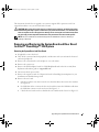
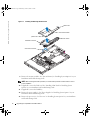
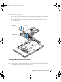
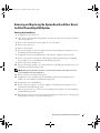
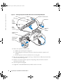
D8781bk0.book Page 1 Wednesday, October 6, 2004 3:43 PM
Dell™ PowerEdge™ 1850
and 2850 Systems
Upgrading Your System Board
and Riser Board
w w w. d e l l . c o m | s u p p o r t . d e l l . c o m
D8781bk0.book Page 2 Wednesday, October 6, 2004 3:43 PM
Notes, Notices, and Cautions
NOTE: A NOTE indicates important information that helps you make better use of your computer.
NOTICE: A NOTICE indicates either potential damage to hardware or loss of data and tells you how to avoid the
problem.
CAUTION: A CAUTION indicates a potential for property damage, personal injury, or death.
____________________
Information in this document is subject to change without notice.
© 2004 Dell Inc. All rights reserved.
Reproduction in any manner whatsoever without the written permission of Dell Inc. is strictly forbidden.
Trademarks used in this text: Dell, the DELL logo, and PowerEdge are trademarks of Dell Inc.
Other trademarks and trade names may be used in this document to refer to either the entities claiming the marks and names or their products.
Dell Inc. disclaims any proprietary interest in trademarks and trade names other than its own.
September 2004
P/N D8781
Rev. A00
D8781bk0.book Page 3 Wednesday, October 6, 2004 3:43 PM
This document describes how to upgrade your system to support PCI-e expansion cards. Your
upgrade kit includes a new system board and riser board.
CAUTION: Many repairs may only be done by a certified service technician. You should only perform
troubleshooting and simple repairs as authorized in your product documentation, or as directed by the
online or telephone service and support team. Damage due to servicing that is not authorized by Dell is
not covered by your warranty. Read and follow the safety instructions that came with the product.
NOTE: See your Installation and Troubleshooting Guide for detailed instructions on removing or
replacing components.
Removing and Replacing the System Board and Riser Board
In A Dell™ PowerEdge™ 1850 System
Removing the System Board and Riser Board
1
If applicable, remove the bezel.
2
Turn off the system and attached peripherals, and disconnect the system from the electrical
outlet and peripherals.
3
Remove the system from the rack and place it on a work surface.
4
Remove the system cover.
5
Remove the SCSI backplane board. See "SCSI Backplane Board" in the Service-Only Parts
Replacement Procedures guide on support.dell.com.
6
Disconnect the fan power cables.
7
Remove the expansion cards. See "Expansion Cards" in "Installing System Options" in your
Installation and Troubleshooting Guide.
8
Remove the riser board:
a
Lift the two plastic rivets that secure the riser board insulator, then remove the insulator.
See Figure 1-1.
b
If a SCSI data cable is connected to the riser board, disconnect the SCSI data cable from
the SCSI data connector on the riser board. See Figure 1-1.
c
Unlock the riser board cam lever, then lift the riser board from the chassis. See Figure 1-1.
Upgrading Your System Board and Riser Board
3
D8781bk0.book Page 4 Wednesday, October 6, 2004 3:43 PM
www.dell.com | support.dell.com
Figure 1-1.
Installing and Removing the Riser Board
plastic rivet
riser board insulator
plastic rivet
riser board
SCSI data connector
riser board cam lever
9
Remove the memory modules. See "System Memory" in "Installing System Options" in your
Installation and Troubleshooting Guide.
NOTE: While removing the memory modules, record the memory module socket locations to ensure
proper installation.
4
10
If applicable, remove the RAC card. See "Installing a RAC Card" in "Installing System
Options" in your Installation and Troubleshooting Guide.
11
If applicable, remove the RAID key.
12
Remove the power supply(s). See "Power Supplies" in "Installing System Options" in your
Installation and Troubleshooting Guide.
13
Remove the processor(s). See "Processor" in "Installing System Options" in your Installation
and Troubleshooting Guide.
Upgrading Your System Board and Riser Board
D8781bk0.book Page 5 Wednesday, October 6, 2004 3:43 PM
14
To remove the system board:
a
Lift up the blue retention pin and slide the system board towards the front of the system
to disengage the board from the retention tabs on the chassis. See Figure 1-2.
b
Raise the back edge of the board slightly to clear the chassis, then lift the system board
out of the system.
Figure 1-2. Removing the System Board
slots
retention pin
system board
tabs
Installing the New System Board and Riser Board
1
Unpack the new system board.
2
Carefully lower the system board into the chassis until the tabs on the chassis fit through the
corresponding slots in the system board. See Figure 1-2.
3
Slide the system board towards the back of the chassis until the retention pin engages.
4
Replace the memory modules in their original locations.
Upgrading Your System Board and Riser Board
5
www.dell.com | support.dell.com
D8781bk0.book Page 6 Wednesday, October 6, 2004 3:43 PM
6
5
Replace the processor(s).
6
If applicable, replace the RAC card.
7
If applicable, replace the RAID key.
8
Replace the power supply(s).
9
Install the new riser board provided in your upgrade kit.
a
Raise the riser board cam lever to a vertical position. See Figure 1-1.
b
Lower the riser board into position
•
The cam lever fits through the opening near the outer edge of the riser board.
•
Align the connector on the underside of the riser board with the corresponding
connector on the system board.
c
When you are certain the riser board is correctly aligned with the system board, carefully
close the cam lever to lock the riser board into place.
d
If you disconnected the SCSI data cable while removing the riser board, reconnect the
cable to the riser board.
10
Place the plastic riser board insulator over the riser board and press down on the two plastic
rivets to secure the insulator.
11
Reconnect the fan power cables.
12
Replace the SCSI backplane board and reinstall the SCSI hard drives. See "SCSI Backplane
Board" in the Service-Only Parts Replacement Procedures guide on support.dell.com.
13
Reinstall the cover.
14
If applicable, reattach the bezel.
Upgrading Your System Board and Riser Board
D8781bk0.book Page 7 Wednesday, October 6, 2004 3:43 PM
Removing and Replacing the System Board and Riser Board
In A Dell PowerEdge 2850 System
Removing the System Board
1
If applicable, remove the bezel.
2
Turn off the system and attached peripherals, and disconnect the system from the electrical
outlet and peripherals.
3
Remove the system from the rack and place it on a work surface.
4
Remove the system cover.
5
Remove the front fans.
6
Remove the expansion cards. See "Expansion Cards" in "Installing System Options" in your
Installation and Troubleshooting Guide.
7
If applicable, disconnect the RAID battery cable from the expansion-card riser board.
8
Remove the expansion-card cage. See "Removing the Expansion-Card Cage" in "Installing
System Options" in your Installation and Troubleshooting Guide.
9
Remove the memory module cover.
10
Remove the memory modules. See "System Memory" in "Installing System Options" in your
Installation and Troubleshooting Guide.
NOTE: While removing the memory modules, record the memory module socket locations to ensure
proper installation on the new system board.
11
Remove the back fans and the back-fan tray.
12
If applicable, remove the RAC card. See "Installing a RAC Card" in "Installing System
Options" in your Installation and Troubleshooting Guide.
13
If applicable, remove the RAID key.
14
Remove the power supply(s). See "Power Supplies" in "Installing System Options" in your
Installation and Troubleshooting Guide.
15
Remove the processor(s). See "Processor" in "Installing System Options" in your Installation
and Troubleshooting Guide.
16
Raise the drive-bay retraction bar and swing it toward the front of the chassis to disengage the
SCSI backplane from the system board. See Figure 1-3.
Upgrading Your System Board and Riser Board
7
D8781bk0.book Page 8 Wednesday, October 6, 2004 3:43 PM
www.dell.com | support.dell.com
Figure 1-3.
Removing the System Board
system board
slots
retention pin
tabs
drive-bay
retraction bar
17
18
8
Remove the front-fan tray:
a
Press and hold the front-fan tray release button.
b
Slide the front-fan tray to the right until it stops.
c
Lift the front-fan tray from its three securing posts.
To remove the system board:
a
Lift up the blue retention pin and slide the system board towards the front of the system
to disengage the board from the retention tabs on the chassis. See Figure 1-3.
b
Raise the back edge of the board slightly to clear the chassis, then lift the system board
out of the system.
Upgrading Your System Board and Riser Board
D8781bk0.book Page 9 Wednesday, October 6, 2004 3:43 PM
Installing the New System Board and Riser Board
1
Unpack the new system board.
2
Carefully lower the system board into the chassis until the tabs on the chassis fit through the
corresponding slots in the system board.
3
Slide the system board towards the back of the chassis until the retention pin engages.
4
Replace the front-fan tray:
a
Place the front-fan tray over the three securing posts.
b
Slide the front-fan tray to the left until it locks into position.
5
Replace the front fans.
6
Raise the drive-bay retraction bar and rotate it toward the back of the chassis until it is
completely flush with the top of the drive cage. See Figure 1-3.
7
Replace the memory modules.
8
Replace the memory module cover.
9
Replace the processor(s).
10
If applicable, replace the RAC card.
11
If applicable, replace the RAID key.
12
Replace the back-fan tray and the back fans.
13
Replace the power supply(s).
14
Replace the riser board in the expansion-card cage with the new riser board. See "Upgrading
the Dell PowerEdge 2850 Expansion-Card Riser Board."
15
Reinstall the expansion-card-cage. See "Replacing the Expansion-Card Cage" in "Installing
System Options" in your Installation and Troubleshooting Guide.
16
If applicable, reconnect the RAID battery cable to the riser board. See Figure 1-4.
17
Reinstall the cover.
18
If applicable, reattach the bezel.
Upgrading the Dell PowerEdge 2850 Expansion-Card Riser Board
1
If applicable, remove the RAID memory module from the expansion-card riser board.
2
Press both release tabs on the expansion-card guide and swing open the guide. See Figure 1-4.
Upgrading Your System Board and Riser Board
9
D8781bk0.book Page 10 Wednesday, October 6, 2004 3:43 PM
www.dell.com | support.dell.com
Figure 1-4. Removing the Expansion-Card Riser Board From a Dell PowerEdge 2850 System
slots
expansion-card riser board
tabs
retention pin
RAID
memory
module
connector
RAID
battery
connector
expansion
card
openings
expansion-card
guide
expansion-card
guide release
tabs (2)
3
10
Remove the expansion-card riser board:
a
Pull the riser retention pin. See Figure 1-4.
b
While pulling the retention pin, slide the riser board away from the expansion card
openings.
c
Lift the expansion-card riser board from the six securing tabs.
4
Place the riser board in the expansion-card cage so that the tabs are fully inserted in the slots
on the riser board. See Figure 1-4.
5
Slide the riser board toward the expansion card openings until you feel the riser-board
retention pin snap into place.
6
Close the expansion-card guide.
7
If applicable, reinstall the RAID memory module onto the riser board.
Upgrading Your System Board and Riser Board
D8781bk0.book Page 1 Wednesday, October 6, 2004 3:43 PM
D8781bk0.book Page 2 Wednesday, October 6, 2004 3:43 PM
Printed in the U.S.A.
D8781bk0.book Page 1 Wednesday, October 6, 2004 3:43 PM
D8781bk0.book Page 2 Wednesday, October 6, 2004 3:43 PM
Printed in Malaysia.
D8781bk0.book Page 1 Wednesday, October 6, 2004 3:43 PM
D8781bk0.book Page 2 Wednesday, October 6, 2004 3:43 PM
Printed in Brazil.
D8781bk0.book Page 1 Wednesday, October 6, 2004 3:43 PM
D8781bk0.book Page 2 Wednesday, October 6, 2004 3:43 PM
Printed in Ireland.
D8781bk0.book Page 1 Wednesday, October 6, 2004 3:43 PM
D8781bk0.book Page 2 Wednesday, October 6, 2004 3:43 PM
Printed in China.