1
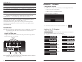
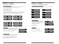
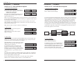
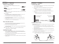
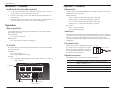
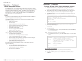
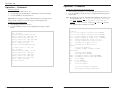
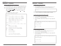
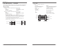
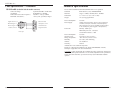
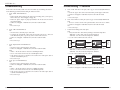
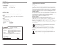
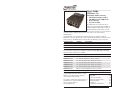
User’s Guide
S4TEF10xx-11x
Stand-Alone Media Converter
• Twisted-Pair Copper to Fiber
• 10/100Base-TX to 100Base-FX
• RS-232 to Fiber
• (4) T1/E1 to Fiber
The S4TEF10xx-11x media converter is
designed to extend signals from a 10Base-T
Ethernet/100Base-TX Fast Ethernet port, an
RS-232 data port, and up to four (4) T1/E1
network ports over fiber. The Ethernet, RS-232, and T1/E1 interfaces are independent of
each other and the signals from these ports can be sent over the fiber interface
simultaneously.
The S4TEF10xx-11x is designed to be installed in pairs. For example, install one
S4TEF1011-110 as the local media converter and another S4TEF1011-110 as the remote
media converter. All S4TEF10xx-11x models have the following copper connectors.
Connector Type
Ethernet
RS-232
T1
Number
1
1
4
Description
RJ-45, 100 Mb/s, 100 m (328 ft.)*
6-pin, DIN serial 3.2 m (10 ft.)*
RJ-48
The various fiber connectors are available on separate models. Both duplex and single
mode fiber optic converters are available:
Part Number
S4TEF1011-110
S4TEF1013-110
S4TEF1014-110
S4TEF1015-110
S4TEF1016-110
S4TEF1017-110
S4TEF1018-110
Duplex Fiber-Optic - 100Base-FX
ST, 1300 nm multimode, 2 km (1.2 miles)*
SC, 1300 nm multimode, 2 km (1.2 miles)*
SC, 1310 nm single mode, 20 km (12.4 miles)*
SC, 1310 nm single mode, 40 km (24.8 miles)*
SC, 1310 nm single mode, 60 km (37.2 miles)*
SC, 1550 nm single mode, 80 km (49.7 miles)*
MT-RJ, 1300 nm multimode, 2 km (1.2 miles)*
S4TEF1029-11x
(Single mode, single fiber models are listed on page 2.)
*Typical maximum cable distance. Actual
distance is dependent upon the physical
characteristics of the network.
The chassis version of the media converter is
C4TEF10xx-11x. For more information, see
the user’s guide on-line at:
www.transition.com.
Installation . . . . . . . . . . . . . . . . . .2
Operation . . . . . . . . . . . . . . . . . .10
Cable Specifications . . . . . . . . . .19
Technical Specifications . . . . . . .23
Troubleshooting . . . . . . . . . . . . .24
Contact Us . . . . . . . . . . . . . . . . .26
Compliance Information . . . . . . .27
S4TEF10xx-11x
Part Number
Fiber-Optic - Single Fiber, Single Mode, 100Base-FX
S4TEF1029-110
SC, 1310 mn TX/1550 nm RX, 20 km (12.4 miles)*
S4TEF1029-111
SC, 1550 mn TX/1310 nm RX, 20 km (12.4 miles)*
Note: S4TEF1029-110 and S4TEF1029-111 are intended to be installed in the same
link where one is the local converter and the other is the remote converter.
SC, 1310 mn TX/1550 nm RX, 40 km (24.8 miles)*
S4TEF1029-112
S4TEF1029-113
SC, 1550 mn TX/1310 nm RX, 40 km (24.8 miles)*
Installation -- Continued
Configuration switches
The S4TEF10xx-11x media converter has two (2) sets of configuration switches.
•
Set #1 (upper) sets the T1/E1 options.
•
Set #2 (lower) sets the serial/Ethernet options.
Switch Set #1 (upper): T1/E1 Options
Note: S4TEF1029-112 and S4TEF1029-113 are intended to be installed in the same
link where one is the local converter and the other is the remote converter.
S4TEF1035-110
SC, 1550 nm single mode, 120 km (74.6 miles)*
*Typical maximum cable distance. Actual distance is dependent upon the physical
characteristics of the network. (TX) = transmit, (RX) = receive
The information in this user’s guide is subject to change. For the most up-to-date
information on the S4TEF10xx-11x media converter, see the user’s guide on-line at:
www.transition.com.
Switch Set #2 (lower): Serial / Ethernet Options
Use a flat blade screwdriver to set the switches as shown:
Installation
up
Note: Because of proprietary communication over fiber, the S4TEF10xx-11x is required
to be installed in pairs, where one is the local converter and the other is the
remote converter.
Copper and fiber ports
The figure below illustrates the locations of the fiber port, the Ethernet port, the RS232 port, and the four (4) T1/E1 ports.
T1/E1 ports
LNK
AIS
1
LNK
AIS
2
Key:
LNK
AIS
LNK
3
AIS
down
Switch set #1 - T1/E1 options
1, 2, 3, 4 - Line settings
Switches 1, 2, 3, and 4 are used to setup the line settings for the T1/E1 ports. The
selected setting applies to all four (4) T1/E1 channels.
1 2 3 4
1 2 3 4
DSX-1, 100 ohm, 0-133 ft. (0-40.5 m)
DS1, 100 ohm, 0 dB LBO
DSX-1, 100 ohm, 133-266 ft. (40.5-81 m)
DS1, 100 ohm, -7.5 dB LBO
DSX-1, 100 ohm, 266-399 ft. (81-122 m)
DS1, 100 ohm, -15 dB LBO
DSX-1, 100 ohm, 399-533 ft. (122-162 m)
DS1, 100 ohm, -22.5 dB LBO
DSX-1, 100 ohm, 533-655 ft. (162-200 m)
E1, 120 ohm
4
PWR
LKF
TX 100Base-FX
fiber port
RX 10/100Base-TX
Ethernet port
RS-232
RS-232 port
J1, 110 ohm, 0-655 ft. (0-200 m)
Note: An RS-232 cable with a 6-pin DIN connector and a DB-9 connector is included
with the S4TEF10xx-11x media converter.
2
24-hour Technical Support: 1-800-260-1312 International: 00-1-952-941-7600
[email protected] -- Click the “Transition Now” link for a live Web chat.
3
S4TEF10xx-11x
Installation -- Continued
Installation -- Continued
Switch set #1 - T1/E1 options
Switch set #2 - serial and ethernet options
5, 6, 7, 8 - Loop-Back settings
1, 2, 3 - Serial connection speed line settings
The loop-back setting is used for installation and network debugging procedures. Each
of the T1/E1 ports can be individually set for loop-back mode:
Switches 1, 2, and 3 on switch set #2 are used to set the serial connection speed.
1 2 3
• Switch 5 controls T1/E1 port 1
• Switch 6 controls T1/E1 port 2
• Switch 7 controls T1/E1 port 3
• Switch 8 controls T1/E1 port 4
When the loop-back switch for a particular T1/E1 port is enabled, the port loops the
signal from the receive port back to the transmit port. The T1/E1 loop-back test
scenarios are described in detail in under Troubleshooting, on page 24.
6
5
up
up
Disable Loop-Back on T1/E1 port 1
Disable Loop-Back on T1/E1 port 2
Enable Loop Back on T1/E1 port 2
7
19200 baud
2400 baud
38400 baud
4800 baud
57600 baud
9600 baud
115200 baud
4. Enable/disable parity
When parity is enabled, an additional bit is
added to the 8-bit signal to identify whether
the signal is sent successfully. Use switch 5 to
send odd or even signal parity.
8
up
Disable Loop-Back on T1/E1 port 3
1200 baud
down
down
Enable Loop-Back on T1/E1 port 1
1 2 3
up
Disable Loop-Back on T1/E1 port 4
4
up
Disable Parity
down
Up - Disable parity.
down
Enable Loop-Back on T1/E1 port 3
down
Down - Enable parity.
Enable Parity
Enable Loop-Back on T1/E1 port 4
9 - Transmit AIS
up - Enable the transmit AIS (Alarm Indication Signal)
on loss of the carrier signal. This function is un-framed
and applies to ALL channels, both copper and fiber.
5. Parity select
10
up
Down - Select even serial parity.
Data Mode
This switch is inactive if switch 4 is (up).
down - Disable the transmit AIS function.
down
Local Management Mode
5
up
Up - Select odd serial parity.
Odd Serial Parity
down
Even Serial Parity
10 - RS-232 Port Mode
up - Data port mode (normal operation). Transmits data
to a desk top computer or other data collection device
down - Local (auxiliary) management mode. See the
SNMP section (page 12) for the commands that are
supported via the RS-232 connector.
4
24-hour Technical Support: 1-800-260-1312 International: 00-1-952-941-7600
[email protected] -- Click the “Transition Now” link for a live Web chat.
5
S4TEF10xx-11x
Installation — Continued
Installation -- Continued
Switch set #2 - serial and ethernet options
6 - Twisted-pair Auto-Negotiation
Up (Enabled) - The media converter “advertises”
ALL rate and mode capabilities to the network:
• 100 Mb/s full- or half-duplex
• 10 Mb/s full- or half-duplex
The media converter brings up the Ethernet link to
the highest speed and mode possible for all the
attached network devices.
Switch set #2 - serial and ethernet options
9 - Transparent Link Pass-Through
6
up
Down - Disable Link Pass-Through
Enable Auto-Negotiation
Enable Link Pass-Through
down
down
Disable Link Pass-Through
Disable Auto-Negotiation
down (Disabled) - The bridging media converter does not “advertise” the rate and
mode capabilities to the network. Switch 7 and switch 8 are then used to set the speed
and mode for the Ethernet link.
Note: Switch 7 and 8 are inactive if switch 6 is enabled (up).
7 - Ethernet speed
9
Up - Enable Link Pass-Through
When selected, Auto-Negotiation allows a twisted-pair link to become operational only
after the Auto-Negotiation function matches network speed capabilities at both ends of
the twisted-pair copper segment.
The Transparent Link Pass-Through feature allows the media converter to monitor the
Ethernet copper RX (receive) ports for loss of signal. For example, when the Ethernet
copper link on the near end device is lost (1), the local media converter transmits a
signal to the remote media converter (2), thus, “passing through” the link loss. The
remote media converter disables the Ethernet copper link to the far-end device (3),
which prevents the loss of valuable data unknowingly transmitted over an invalid link.
It is important to remember that, although the Ethernet copper link has been disabled,
the fiber link is still valid (4). Thus, there is no disruption to the transfer of T1/E1 or
RS-232 data signals over the fiber link.
7
up (100Base-TX) - Sets the Ethernet port to
100Base-TX (100 Mb/s).
down (10Base-T) - Sets the Ethernet port to
10Base-T (10 Mb/s).
up
up
local converter sends a
loss signal over the fiber link
Ethernet Speed = 100 Mb/s
Near-End
Device
down
Ethernet Speed = 10 Mb/s
1
Local
Media
Converter
original fault on the
Ethernet copper link
2
4
fiber link is still valid
Remote
Media
Converter
3
Far-End
Device
remote converter disables
the Ethernet copper link
8 - Ethernet node
up (Full-Duplex) - Sets the Ethernet port to full-duplex mode. The twisted-pair cable
distances are constrained by the cable requirements (see pages 1 and 2 for the cable
specifications for the various S4TEF10xx-11x models).
down (Half-Duplex) - Sets the Ethernet port to halfduplex mode. The twisted-pair cable distances are
constrained by the 512-bit rule:
In a half-duplex network, the maximum cable
lengths are determined by the round trip delay
limitations of each Fast Ethernet collision domain.
(A collision domain is the longest path between any
two terminal devices, e.g. a terminal, switch, or
router.)
8
up
Full-Duplex
down
10 - Fiber Loop-Back
10
Up - Disable fiber loop-back.
Down - Enable fiber loop-back.
The loop-back setting is used for installation and Disables Loop-Back
network debugging procedures. When the fiber
loop-back function is enabled, the fiber port loops
all T1/E1 and Ethernet signals from the receive
Enables Loop-Back
port back to the transmit port. The fiber loopback test scenarios are described in detail on page 18.
up
down
Half-Duplex
The 512-bit rule determines the maximum length of cable permitted by calculating the
round-trip delay in bit-times (BT) of a particular collision domain. If the result is less
than or equal to 512 BT, the path is good.
For more information on the 512-bit rule, see the white paper titled “Collision
Domains” on the Transition Networks website at: www.transition.com.
6
24-hour Technical Support: 1-800-260-1312 International: 00-1-952-941-7600
[email protected] -- Click the “Transition Now” link for a live Web chat.
7
S4TEF10xx-11x
Installation — Continued
Installation -- Continued
The media converter mode is determined by the switch
setting (see pages 3 - 7).
Software:
1.
Locate or build ITU-compliant fiber cable with male, two-stranded TX to RX
connectors installed at both ends.
S
Software Mode
2.
Connect the fiber cables to the local S4TEF10xx-11x media converter as
described:
•
Connect the male TX cable connector to the female TX port.
•
Connect the male RX cable connector to the female RX port.
Connect the fiber cables to the remote S4TEF10xx-11x media converter as
described:
•
Connect the male TX cable connector to the female RX port.
•
Connect the male RX cable connector to the female TX port.
H
Hardware:
S
The jumper is located on the circuit board, inside the media
converter housing.
Install the fiber cable
H
Hardware/software jumper
Hardware Mode
The media converter mode is determined by the most-recently saved, on-board
microprocessor settings.
3.
To set the jumper:
1. Using a small screwdriver, remove the four (4) screws that secure the cover
and carefully remove the cover from the media converter.
2.
Locate the jumper near the back end on the upper circuit board.
3.
Using small needle-nosed pliers or similar device, move the jumper to the
desired position (see above).
4.
Carefully replace the cover on the media converter and replace the four (4)
screws that secure the cover to the media converter.
Connect the fiber cable
to the local media
converter as shown.
Connect the fiber cable
to the remote media
converter as shown
RX
RX
TX
TX
Power the media converter
1.
Connect the barrel connector on the power adapter to the media converter’s
power port (located on the back of the media converter).
2.
Connect the power adapter plug to AC power.
3.
Verify that the media converter is powered by observing the illuminated LED
power indicator light.
Note: For DC power, consult the user’s guide for the Transition Networks
SPS1872-xx DC external power supply.
Install the T1/E1 cable
1.
Locate or build ITU-compliant copper cable with straight-through RJ-48
connectors installed at both ends. (See pages 19 thru 21 for the proper cable
specifications for your network application.).
2.
Connect the RJ-48 connector at one end of the cable to one of the T1/E1 ports
on the S4TEF10xx-11x media converter.
3.
Connect the RJ-48 connector at the other end of the cable to the T1/E1 port on
the other device.
Install the ethernet cable
Ensure that the correct cable type is installed to support the highest speed and mode
of operation to be selected.
1.
Locate or build IEEE 803.2™ compliant 10Base-T or 100Base-TX cables,
with straight-through RJ-45 cable, and with straight-through RJ-45 connectors
installed at both ends.
2.
Connect the RJ-45 connector at one end of the cable to the RJ-45 port on the
S4TEF10xx-11x media converter.
3.
Connect the RJ-45 connector at the other end of the cable to the RJ-45 port on
the other device (switch, workstation, etc.).
Note: The MDI (straight-through) or MDI-X (crossover) cable connection is
configured automatically, according to the network conditions.
RJ-45 port
on the media
converter
8
24-hour Technical Support: 1-800-260-1312 International: 00-1-952-941-7600
RJ-45 port
on the other device
(switch, work station, etc.)
[email protected] -- Click the “Transition Now” link for a live Web chat.
9
S4TEF10xx-11x
Installation -- Continued
Operation -- Continued
Install the RS-232 data cable (included)
Ethernet LEDs
1.
Use the enclosed RS-232 data cable with a male, DIN 6-pin connector on one
end and a DB-9 connector installed on the other end.
Use the bi-color status LEDs (embedded in the 10/100Base-TX RJ-45 connector) to
monitor the Ethernet connections.
2.
Connect the DIN 6-pin connector to the RS-232 port on the S4TEF10xx-11x
media converter.
Duplex/Link LED:
Amber = A link on the half-duplex twisted-pair copper link.
3.
Connect the DB-9 connector at the other end of the cable to the RS-232 port on
a computer or other device that is used to collect and display data.
Flashing Amber = Activity on the half-duplex copper link.
Green = A link on the full-duplex twisted-pair copper link.
Flashing Green = Activity on the full-duplex copper link.
Operation
Speed LED:
Amber = 10 Mb/s operation.
Fiber network LEDs
Green = 100 Mb/s operation.
Use the status LEDs next to the fiber port to monitor the media converter and the
fiber network connections.
AutoCross™
The AutoCross feature allows either straight-through (MDI) or crossover (MDI-X)
cables to be used when connecting to devices such as hubs, transceivers, or network
interface cards (NICs). AutoCross determines the characteristics of the cable
connection and automatically configures the unit to link up, regardless of the cable
configuration.
LKF (fiber link)
ON = Fiber link connection.
PWR (power)
ON = Connection to external AC or DC power.
Dry-contact relay
T1/E1 LEDs
Each T1/E1 link has a pair of LEDs embedded in the RJ-48 connector that monitor
the status of the link.
LNK LED
ON = T1/E1 link detected.
OFF= T1/E1 signal lost or no signal.
AIS LED
ON = AIS (Alarm Indication Signal) detected. Failure of the device connected
to the T1/E1 port.
LNK
T1/E1 LEDs
AIS
1
LNK
AIS
2
LNK
AIS
LNK
3
All four T1/E1 ports are equipped with an RJ-48 T1/E1 port
dry-contact relay. The relay closes if the power
3
is lost or if any of the individual T1/E1 links are relay
lost. The operational rating on pins 3 and 6 are
6
0-30 VDC, 100 mA (maximum).
RJ-48C connector
Optional accessories
The following items are available from Transition Networks
Part Number
SPS-1872-SA
Description
Optional External Power Supply; 18-72VDC Stand-Alone
Output: 12.6VDC, 1.0 A
WMBL
WMBV
WMBD
Optional Wall Mount Bracket; 4.0 in. (102 mm)
Optional Vertical Mount Bracket; 5.0 in. (127 mm)
Optional DIN Rail Mount Bracket; 5.0 in. (127 mm)
AIS
4
PWR
LKF
TX 100Base-FX
Fiber LEDs
10
RX 10/100Base-TX
RS-232
Speed Duplex/Link
Ethernet LEDs
24-hour Technical Support: 1-800-260-1312 International: 00-1-952-941-7600
[email protected] -- Click the “Transition Now” link for a live Web chat.
11
S4TEF10xx-11x
Operation — Continued
Remote management function
The S4TEF10xx-11x can be remotely managed when connected via fiber cable to a
local C4TEF10xx-11x slide-in-module media converter that is installed in a managed
Transition Networks PointSystem™ chassis. The SNMP section (below) lists the
commands that can be used to monitor and manage a networked S4TEF10xx-11x
media converter at a remote location. For more details, see the C4TEF10xx-11x
user’s guide on-line at: www.transition.com.
Operation -- Continued
Accessing the local RS232 factory maintenance interface
1.
Make sure that this Device is configured for accessing the maintenance
interface via the RS232 port (Switch #10, on Bank #1, down. See page 4).
2.
Attach RS232 cable from the terminal to the DIN6 plug. The settings for the
baud rate and parity are the same as the settings for the Serial Transport.
3.
To display the main screen, press the ENTER key and a header message will
appear on the screen:
SNMP
T1/E1x4 with Ethernet to Fiber Converter (S4TEF1011-110)
Version: C [050728LO] SN: 676.
Copyright (c) 2005 Transition Networks
Software Mode!
See the on-line documentation that comes with Transition Networks FocalPoint™
software for applicable commands and usage.
Use SNMP at an attached terminal or at a remote location to monitor the media
converter by monitoring:
•
Media converter power
•
Fiber link status
•
Copper link status for each T1/E1 (AIS, link)
•
Copper link status for Ethernet (link, speed, duplex)
•
RS-232 status (speed, bits, parity, stop)
•
All hardware switch settings
•
AIS detected copper link and fiber link
•
Model #, serial #, PIC revision
•
HW revision, group string, connectors
Also, use SNMP to enter network commands that:
•
Local and remote fiber loop-back
•
Local and remote T1/E1 loop-back for each channel
•
T1/E1 line options (DS1, DSX-1, J1, D1, AIS)
•
Ethernet settings (Auto-Negotiation, speed, duplex, Link Pass-Through)
•
RS-232 settings (speed, bits, parity, stop)
•
T1/E1 monitor modes and loop-back modes
•
Boot-load firmware (local unit only)
The local (auxiliary) factory maintenance interface via the RS-232 connector
supports the following:
•
Switch selection for the RS-232 interface
•
Access to all local and remote status information
•
Perform all local and remote commands
•
Operate at selected baud rates
12
24-hour Technical Support: 1-800-260-1312 International: 00-1-952-941-7600
Type 'L' to login
4.
To access the maintenance interface, press the letter 'L' key to login and a
password prompt will appear:
Password?
5.
Type the password:
a. If a password has been set, enter the password, then press the ENTER key
to access the main menu.
Note: If you forget the password, contact techsupport.
b. If no password has been set, press the ENTER key to access the main
menu.
Main Menu:
p XXXXXXXX
d
c [l/r]
u
b
r
RETURN
q
->
-
Change password (Maximum of 8 characters)
Display current configuration (Rev)
Go to Configuration Menu (local/remote)
Upgrade Remote Device's firmware via fiber
Bypass hardware mode
Reset Device
List of commands
Logout
Accessing the menu commands:
1.
At the prompt, press the letter key of the desired menu command.
2.
Press the ENTER key and the screen will show the menu of the selected
command.
[email protected] -- Click the “Transition Now” link for a live Web chat.
13
SBFTF10xx-10x
Operation -- Continued
Operation -- Continued
Setting the password:
To show the configuration menu for the local device:
1.
At the prompt, press the letter “P” key.
1.
At the prompt, type the letter “C,” press the spacebar, then type the letter “L.”
2.
At the prompt, type any alphanumeric combination (8 characters maximum)
2.
3.
Press the ENTER key: the password is set.
Press the ENTER key and the local device configuration menu will appear as
shown below:
Important: After setting up or changing command parameter(s) you must save the
change(s) before exiting the screen or the change(s) will not go into effect.
To show the current configuration:
1.
At the prompt, press the letter “D” key.
2.
Press the ENTER key and the current configuration will appear as shown
below:
---- Local Device ---- SN: 676.
Mode: Software
Ethernet: AutoNeg, 100Mbs, HD, LPT
T1/E1 #1: DSX-1 0-133, Xmit AIS, AMI,
T1/E1 #2: DSX-1 0-133, Xmit AIS,
T1/E1 #3: DSX-1 0-133, Xmit AIS, AMI,
T1/E1 #4: DSX-1 0-133, Xmit AIS,
Serial : 9600, No Parity
DMI: Not Detected. VLAN: Disabled
---- Remote Device ---- SN: 676.
Mode: Software
Ethernet: AutoNeg, 100Mbs, FD, LPT
T1/E1 #1: DSX-1 0-133, Xmit AIS,
T1/E1 #2: DSX-1 0-133, Xmit AIS,
T1/E1 #3: DSX-1 0-133, Xmit AIS,
T1/E1 #4: DSX-1 0-133, Xmit AIS,
Serial : 9600, No Parity
DMI: Not Detected.
->
Note: In this menu, the T1/E1/J1 commands for local loopback, for example, type
the command this way: LL, press the spacebar, then type
the port number, press spacebar, then type the
number of the command, in this case (1= enable or 2 = disable).
The command sequence IS NOT case sensitive.
Local Device Configuration Menu:
*T1/E1/J1:
LL x 1 - Local Loopback on T1/E1/J1 Port x ENABLE
LL x 2 - Local Loopback on T1/E1/J1 Port x DISABLE
RL x 1 - Remote Loopback on T1/E1/J1 Port x ENABLE
RL x 2 - Remote Loopback on T1/E1/J1 Port x DISABLE
XE x
- Enable Transmit AIS on LOS for Port x
XD x
- Disable Transmit AIS on LOS for Port x
EB x
- Encoding set to B8ZS on Port x
EA x
- Encoding set to AMI on Port x
*RS-232:
B x
- Serial port baud rate
(1=9600, 2=19200, 3=36400, 4=57600)
*Enet 10/100:
A1
- Autonegotiation ENABLE
A2
- Autonegotiation DISABLE
TLPT1 - Transparent Link Pass Through ENABLE
TLPT2 - Transparent Link Pass Through DISABLE
F10
- Force 10Mbps
F100
- Force 100Mbps
FF
- Force Full Duplex
FH
- Force Half Duplex
S
Q
->
14
24-hour Technical Support: 1-800-260-1312 International: 00-1-952-941-7600
- Save new Configuration and Exit
- Exit without saving Configuration
[email protected] -- Click the “Transition Now” link for a live Web chat.
15
S4TEF10xx-11x
Operation -- Continued
Operation -- continued
To show the configuration menu for the remote device:
To update the PIC code of a remote device:
1.
At the prompt, type the letter “C,” press the spacebar, then type the letter “R.”
1.
At the prompt, type the letter “U.”
2.
Press the ENTER key and the remote device configuration menu will appear:
2.
Press the ENTER key and the code will start to transfer. On the screen, the
incrementing percent line shows the percent of the transferring code:
Note: In this menu, the T1/E1/J1 commands for remote loopback, for example,
type the command this way: LL, press the spacebar, then
type the port number, press spacebar, then type
the number of the command, in this case (1= enable or 2 =
disable).
The command sequence Is Not case sensitive.
Fiber Load...Transferring of binary pic code to remote...
6 percent...
Note: This command will take several minutes to complete. Do Not power down
the device or break the fiber connection during this code transfer.
Remote Device Configuration Menu:
To enable hardware bypass mode for software control:
*T1/E1/J1:
LL x 1 - Local Loopback on T1/E1/J1 Port x ENABLE
LL x 2 - Local Loopback on T1/E1/J1 Port x DISABLE
RL x 1 - Remote Loopback on T1/E1/J1 Port x ENABLE
RL x 2 - Remote Loopback on T1/E1/J1 Port x DISABLE
XE x
- Enable Transmit AIS on LOS for Port x
XD x
- Disable Transmit AIS on LOS for Port x
EB x
- Encoding set to B8ZS on Port x
EA x
- Encoding set to AMI on Port x
*RS-232:
B x
- Serial port baud rate (1=9600, 2=19200, 3=36400,
4=57600)
*Enet 10/100:
A1
- Autonegotiation ENABLE
A2
- Autonegotiation DISABLE
TLPT1 - Transparent Link Pass Through ENABLE
TLPT2 - Transparent Link Pass Through DISABLE
F10
- Force 10Mbps
F100
- Force 100Mbps
FF
- Force Full Duplex
FH
- Force Half Duplex
S
Q
->
- Save new Configuration and Exit
- Exit without saving Configuration
1.
At the prompt, type the letter “B.”
2.
Press the ENTER key and a Reset message will appear on the screen.
3.
Type the letter “Y” to Enable H/W Bypass.
4.
Press the ENTER key. When the Reset completes, the “login” prompt will
appear.
-> b
This command will cause reset. Are you SURE you wish to
reset device (y/n)?
Enable H/W Bypass...
Resetting Board!
Type 'L' to login
->
To disable the hardware bypass mode:
1.
At the prompt, type the letter “B” again.
2.
Press the ENTER key and a Reset message will appear on the screen.
3.
Type the letter “Y” to Disable H/W Bypass.
4.
Press the ENTER key. When the Reset completes, the “login” prompt will
appear as show below.
-> b
This command will cause reset. Are you SURE you wish to
reset device (y/n)?
Disable H/W Bypass...
Resetting Board!
Type 'L' to login
->
16
24-hour Technical Support: 1-800-260-1312 International: 00-1-952-941-7600
[email protected] -- Click the “Transition Now” link for a live Web chat.
17
S4TEF10xx-11x
Operation -- continued
The physical characteristics must meet or exceed ITU and IEEE802.3 specifications.
Caution: This command will interrupt T1/E1 and Ethernet traffic. It will take
several seconds to restore the data path. Failure to observe this caution might cause
data loss.
Fiber cable
1.
At the prompt, type the letter “R.”
2.
Press the ENTER key to send the Reset signal to the remote device. Look for
the Type ‘L’ to login prompt, indicating success.
-> r
Reset
Exchanging Config and Serial Number with Remote
Card...wait...
Done.
Type 'L' to login
->
18
Cable Specifications
To Reset the local device:
24-hour Technical Support: 1-800-260-1312 International: 00-1-952-941-7600
Bit Error Rate:
Single mode fiber (recommended):
Multimode fiber (recommended):
Multimode fiber (optional):
<10-9
9 μm
62.5/125 μm
100/140, 85/140, 50/125 μm
S4TEF1011-110
Fiber Optic Transmitter Power:
Fiber Optic Receiver Sensitivity:
Link Budget:
1300 nm multimode
min: -19.0 dBm
max: -14.0 dBm
min: -30.0 dBm
max: -14.0 dBm
11.0 dB
S4TEF1013-110
Fiber Optic Transmitter Power:
Fiber Optic Receiver Sensitivity:
Link Budget:
1300 nm multimode
min: -19.0 dBm
max: -14.0 dBm
min: -30.0 dBm
max: -14.0 dBm
11.0 dB
S4TEF1014-110
Fiber-optic Transmitter Power:
Fiber-optic Receiver Sensitivity:
Link Budget:
1310 nm single mode
min: -15.0 dBm
max: -8.0 dBm
min: -31.0 dBm
max: -8.0 dBm
16.0 dB
S4TEF1015-110 (long haul)
Fiber-optic Transmitter Power:
Fiber-optic Receiver Sensitivity:
Link Budget:
1310 nm single mode
min: -8.0 dBm
max: -2.0 dBm
min: -34.0 dBm
max: -7.0 dBm
26.0 dB
S4TEF1016-110 (extra long haul)
S4TEF1017-110 (long wave length)
Fiber-optic Transmitter Power:
Fiber-optic Receiver Sensitivity:
Link Budget:
1310 nm single mode
1550 nm single mode
min: -5.0 dBm
max: 0.0 dBm
min: -34.0 dBm
max: -7.0 dBm
29.0 dB
S4TEF1018-110
Fiber-optic Transmitter Power:
Fiber-optic Receiver Sensitivity:
Link Budget:
1300 nm multimode
min: -19.0 dBm
max: -14.0 dBm
min: -30.0 dBm
max: -14.0 dBm
11.0 dB
S4TEF1029-110
S4TEF1029-111
Fiber-optic Transmitter Power:
Fiber-optic Receiver Sensitivity:
Link Budget:
1310 nm TX/1550 nm RX simplex
1550 nm TX/1310 nm RX simplex
min: -13.0 dBm
max: -6.0 dBm
min: -32.0 dBm
max: -3.0 dBm
19.0 dB
S4TEF1029-112
S4TEF1029-113
Fiber-optic Transmitter Power:
Fiber-optic Receiver Sensitivity:
Link Budget:
1310 nm TX/1550 nm RX simplex
1550 nm TX/1310 nm RX simplex
min: -8.0 dBm
max: -3.0 dBm
min: -33.0 dBm
max: -3.0 dBm
25.0 dB
S4TEF1035-110
Fiber-optic Transmitter Power:
Fiber-optic Receiver Sensitivity:
Link Budget:
1550 nm single mode
min: 0.0 dBm
max: 5.0 dBm
min: -36.0 dBm
max: -3.0 dBm
36.0 dB
[email protected] -- Click the “Transition Now” link for a live Web chat.
19
S4TEF10xx-11x
Cable Specifications -- Continued
T1/E1 cable
The fiber optic transmitters on this device meet Class 1 Laser safety requirements per
IEC-825/CDRH standards and complies with 21 CFR1040.10 and 21 CFR1040.11.
Ethernet cable
Category 3: (minimum requirement for 10 Mb/s operation)
Gauge
24 to 22 AWG
Attenuation
11.5 dB/100m @ 5-11 MHz
Maximum cable distance
100 meters
Category 5: (minimum requirement for 100 Mb/s operation)
Gauge
24 to 22 AWG
Attenuation
22.0 dB /100m @ 100 MHz
Maximum cable distance
100 meters
• Straight-through (MDI) or crossover (MDI-X) cable may be used.
• Shielded (STP) or unshielded (UTP) twisted-pair cable may be used.
• Pins 1&2 and 3&6 are the two active pairs in an Ethernet network .
• Use only dedicated wire pairs for the active pins:
(e.g., blue/white & white/blue, orange/white & white/orange, etc.)
• Do not use flat or silver satin wire.
Straight-Through Cable
20
Category 3: (minimum requirement)
Connector:
Electrical network connection:
Mechanical arrangement:
Usage:
Interface codes:
Cable type:
Long Haul T1:
E1:
J1:
DSX-1:
(ring) R
(tip) T
(ring) R1
(tip) T1
Crossover Cable
Twisted Pair #1
1
2
1
2
Twisted Pair #1
1
2
1
2
Twisted Pair #2
3
6
3
6
Twisted Pair #2
3
6
3
6
24-hour Technical Support: 1-800-260-1312 International: 00-1-952-941-7600
1
2
3
4
5
6
7
8
to the
network
RJ-48C
Single 4-wire (Tip/Ring - Tip1/Ring1)
8-position miniature modular jack
1.544 Mb/s access lines
04DU9 (any applicable)
0db, -7.5dp, -15db, -22db
E1 3.0V, 120 ohm
0-655’, 110 ohm
0-133’, 133-266’, 266-399’,
399-533’, 533-655’, 100 ohm
1
2
3
4
5
6
7
8
R
Receive
T
dry contact A
R1
Transmit
T1
dry contact B
(not used)
from the
media converter
[email protected] -- Click the “Transition Now” link for a live Web chat.
21
S4TEF10xx-11x
Technical Specifications
Cable Specifications —Continued
RS-232 cable (included with the media converter)
Connectors Gauge:
Attenuation:
Differential characteristic impedance:
Maximum cable distance:
Signal Ground 3,5
6-pin DIN and DB-9 / 24-22 AWG
20 dB/1000 ft. @ 10 MHz
100 ohm +/- 10% @ 10 MHz
<10 ft (3.2 m) @ 56 kb/s or higher
1
Transmit Signal 1
1
Receive Signal 2
2
3
5
2
3
4
6
Clear to Send 9
4
5
DIN 6-pin
6
2 Receive Data
7
7 Request to Send
8
3 Transmit Data
9
5 Signal Ground
For use with Transition Networks Model S4TEF10xx-11x or equivalent.
Standards
IEEE 802.3™, G.703, AMI/B8Z3/HDB3
Data Rate
Copper: 10 Mb/s, 100 Mb/s; Fiber: 100 Mb/s
Dimensions
3.7" x 4.7" x 1.8" (93 x 120 x 47 mm)
Weight
1 lb. (0.45 kg) approximate
Power Consumption
6.0 watts
Power Supply
12VDC, 0.8A (North Am., Europe, Japan, Latin Am.)
12 VDC, 1.25A (UK, Australia, N.Z., South Africa)
(The external power supply provided with this product
is UL listed by the power supplier’s manufacturer.)
Packet Size
Memory: 256 K bytes
Maximum packet size: 1536 bytes
Unicast MAC addresses: 1000
Power Consumption
6.0 watts
Operating temp:
Storage Temperature:
Humidity:
Altitude:
0°C to 50°C (32°F to 122°F )
-40°C to 85°C (-40°F to 185°F)
5% to 95%, non-condensing
0 to 10,000 feet
Warranty:
Lifetime
DB-9
*Manufacturer’s rated ambient temperature.
Product is certified by the manufacturer to comply with DHHS Rule 21/CFR,
Subchapter J applicable at the date of manufacture.
CAUTION: Visible and invisible laser radiation when open. Do not stare into beam or
view directly with optical instruments. Use of controls, adjustments or the performance
of procedures other than those specified herein may result in hazardous radiation
exposure.
22
24-hour Technical Support: 1-800-260-1312 International: 00-1-952-941-7600
[email protected] -- Click the “Transition Now” link for a live Web chat.
23
S4TEF10xx-11x
2.
Is the “LKF” LED illuminated?
NO
• Check the fiber cables for proper connection.
• Verify that the TX and RX cables on the local media converter are connected
to the RX and TX ports, respectively, on the remote media converter.
• Contact Tech Support: 1-800-260-1312, Int’l: 00-1-952-941-7600.
YES
• Proceed to step 3.
3.
Is the “Duplex/Link” LED illuminated?
NO
• Check the copper cables for proper connection.
• Contact Tech Support: 1-800-260-1312, Int’l: 00-1-952-941-7600.
YES
• Amber = The media converter has selected half-duplex mode.
• Green = The media converter has selected full-duplex mode.
• If the mode is not correct, disconnect and reconnect the twisted pair cable to
restart the initialization process.
• Proceed to step 4.
4.
24
Is the “Speed” LED illuminated?
NO
• Check the copper cables for proper connection.
• Contact Tech Support: 1-800-260-1312, Int’l: 00-1-952-941-7600.
YES
• Amber = The media converter has selected 10Mb/s operation.
• Green = The media converter has selected 100Mb/s operation.
• If the speed is not correct, disconnect and reconnect the twisted pair cable to
restart the initialization process.
• Proceed to step 5.
24-hour Technical Support: 1-800-260-1312 International: 00-1-952-941-7600
6.
Is the “AIS” LED on a T1/E1 port (with a copper cable installed) illuminated?
YES
• The device connected to the T1/E1 port has failed. Correct the device failure.
• Contact Tech Support: 1-800-260-1312, Int’l: 00-1-952-941-7600.
NO
• Proceed to step 7.
7.
Is data transfer failing on the fiber port?
YES
• Verify the local fiber connection by starting a remote fiber loop-back:
- HW mode: set the remote converter to fiber loop-back.
- SW mode: enter the remote fiber loop-back command.
• Use a bit error test unit to run a bit error test.
T1
Local
Converter
Fiber
Remote
Converter
T1
Remote
Device
Is the “PWR” LED illuminated?
NO
• Ensure that the power adapter is the proper type of voltage and cycle frequency
for the outlet (See “Power Supply” on page 15.)
• Ensure the power adapter is properly installed in the media converter and in
the grounded outlet.
• Contact Tech Support: 1-800-260-1312, Int’l: 00-1-952-941-7600.
YES
• Proceed to step 2.
Is the “LNK” LED on a T1/E1 port (with a copper cable installed) illuminated?
NO
• Check the copper cable connected to that T1/E1 port for proper connection.
• Contact Tech Support: 1-800-260-1312, Int’l: 00-1-952-941-7600.
YES
• Proceed to step 6.
• Verify the remote fiber connection by starting a local fiber loop-back:
- HW mode: set the local converter to fiber loop-back.
- SW mode: enter the remote fiber loop-back command.
• Use a bit error test unit to run a bit error test.
T1
Local
Converter
Fiber
Remote
Converter
T1
Bit Error Test
Equipment
1.
5.
Bit Error Test
Equipment
If the media converter fails, isolate and correct the failure by determining the answers
to the following questions and then taking the indicated action:
Troubleshooting -- Continued
Local
Device
Troubleshooting
• Contact Tech Support: 1-800-260-1312, Int’l: 00-1-952-941-7600.
NO
• Contact Tech Support: 1-800-260-1312, Int’l: 00-1-952-941-7600.
[email protected] -- Click the “Transition Now” link for a live Web chat.
25
S4TEF10xx-11x
Contact Us
Compliance Information
Technical support
Technical support is available 24 hours a day.
US and Canada:
1-800-260-1312
International:
00-1-952-941-7600
CE Mark
FCC regulations
Transition now
Chat live via the Web with Transition Networks Technical Support.
Log onto www.transition.com and click the Transition Now link.
Web-Based seminars
Transition Networks provides seminars via live web-based training.
Log onto www.transition.com and click the Learning Center link.
E-Mail
Ask a question anytime by sending an e-mail to our technical support staff.
[email protected]
Address
Transition Networks
6475 City West Parkway
Minneapolis, MN 55344, U.S.A.
Telephone:
952-941-7600
Toll free:
800-526-9267
Fax:
952-941-2322
This equipment has been tested and found to comply with the limits for a Class A digital device,
pursuant to part 15 of the FCC rules. These limits are designed to provide reasonable protection
against harmful interference when the equipment is operated in a commercial environment. This
equipment generates, uses, and can radiate radio frequency energy and, if not installed and used in
accordance with the instruction manual, may cause harmful interference to radio communications.
Operation of this equipment in a residential area is likely to cause harmful interference, in which
case the user will be required to correct the interference at the user's own expense.
Canadian regulations
This digital apparatus does not exceed the Class A limits for radio noise for digital apparatus set out
on the radio interference regulations of the Canadian Department of Communications.
Le présent appareil numérique n'émet pas de bruits radioélectriques dépassant les limites applicables
aux appareils numériques de la Class A prescrites dans le Règlement sur le brouillage
radioélectrique édicté par le ministère des Communications du Canada.
European regulations
Warning This is a Class A product. In a domestic environment this product may cause radio
interference in which case the user may be required to take adequate measures.
Achtung! Dieses ist ein Gerät der Funkstörgrenzwertklasse A. In Wohnbereichen können bei
Betrieb dieses Gerätes Rundfunkstörungen auftreten, in diesem Fäll ist der Benutzer für
Gegenmaßnahmen verantwortlich.
Attention! Ceci est un produit de Classe A. Dans un environment domestique, ce produit risque de
créer des interférences radioélectriques, il appartiendra alors à l'utilsateur de prende les measures
spécifiques appropriées.
CAUTION: RJ connectors are NOT INTENDED FOR CONNECTION TO THE
PUBLIC TELEPHONE NETWORK. Failure to observe this caution could result in
damage to the public telephone network.
Declaration of Conformity
Name of Mfg:
Transition Networks
6475 City West Parkway, Minneapolis MN 55344 U.S.A.
Model:
S4TEF10xx-11x Series Media Converters
Part Number(s):
S4TEF1011-110, S4TEF1013-110, S4TEF1014-110, S4TEF1015-110,
S4TEF1016-110, S4TEF1017-110, S4TEF1018-110, S4TEF1029-110,
S4TEF1029-111, S4TEF1029-112, S4TEF1029-113, S4TEF1035-110
Regulation:
EMC Directive 89/336/EEC
Purpose: To declare that the S4TEF10xx-11x to which this declaration refers is in
conformity with the following standards.
EN 55022:1994 + A1:1995 + A2:1997; EN 55024:1998 + A1+A13546:20002
Der Anschluss dieses Gerätes an ein öffentlickes Telekommunikationsnetz in den EGMitgliedstaaten verstösst gegen die jeweligen einzelstaatlichen Gesetze zur Anwendung der
Richtlinie 91/263/EWG zur Angleichung der Rechtsvorschriften der Mitgliedstaaten über
Telekommunikationsendeinrichtungen einschliesslich der gegenseitigen Anerkennung ihrer
Konformität.
In accordance with European Union Directive 2002/96/EC of the European
Parliament and of the Council of 27 January 2003, Transition Networks will accept
post usage returns of this product for proper disposal. The contact information for this
activity can be found in the 'Contact Us' portion of this document.
I, the undersigned, hereby declare that the equipment specified above conforms to the above
Directive(s) and Standard(s).
Stephen Anderson, Vice-President of Engineering
26
May, 2007
Date
24-hour Technical Support: 1-800-260-1312 International: 00-1-952-941-7600
[email protected] -- Click the “Transition Now” link for a live Web chat.
27
S4TEF10xx-11x
Compliance -- continued
VCCI Class 1 compliance
This equipment is in the 1st Class category (information equipment to be used in commercial and/or
industrial areas) and conforms to the standards set by the Voluntary Control Council For
Interference by Data Processing
Equipment and Electronic Office
Machines aimed at preventing radio
interference in commercial and/or
industrial areas. When used in a
residential area or in an adjacent area
thereto, interference may be caused to
radio and TV receivers, etc. Read the
instructions for correct handling.
Trademark notice
All trademarks and registered trademarks are the property of their respective owners.
Copyright restrictions
© 2005 Transition Networks.
All rights reserved. No part of this work may be reproduced or used in any form or by any means graphic, electronic, or mechanical - without written permission from Transition Networks.
28
Printed in the U.S.A.
33301.F