1
85577_Cover.fm Page 1 Wednesday, September 1, 1999 10:08 AM
Air Conditioning
Clinic
Centrifugal
Water Chillers
One of the Equipment Series
TRG-TRC010-EN
123267$*(
1(&(66$5<
,)0$,/('
,17+(
81,7('67$7(6
BUSINESS REPLY MAIL
FIRST-CLASS MAIL
PERMIT NO. 11
LA CROSSE, WI
POSTAGE WILL BE PAID BY ADDRESSEE
&URSWRZLGWKRIµ
THE TRANE COMPANY
Attn: Applications Engineering
3600 Pammel Creek Road
La Crosse WI 54601-9985
123267$*(
1(&(66$5<
,)0$,/('
,17+(
81,7('67$7(6
BUSINESS REPLY MAIL
FIRST-CLASS MAIL
PERMIT NO. 11
LA CROSSE, WI
POSTAGE WILL BE PAID BY ADDRESSEE
THE TRANE COMPANY
Attn: Applications Engineering
3600 Pammel Creek Road
La Crosse WI 54601-9985
3HUIRUDWLRQµIURPHGJH
'SQQIRX'EVH
;I[ERXXSIRWYVIXLEXSYVIHYGEXMSREPQEXIVMEPWQIIX]SYVIZIVGLERKMRKVIWSYVGIHIZIPSTQIRXRIIHW
4PIEWIXEOIEQSQIRXXSGSQQIRXSRXLIIJJIGXMZIRIWWSJXLMW%MV'SRHMXMSRMRK'PMRMG
'IRXVMJYKEP;EXIV'LMPPIVW
0IZIPSJHIXEMPGMVGPISRI
3RISJXLI)UYMTQIRX7IVMIW
6EXIXLMWGPMRMGJVSQr2IIHW-QTVSZIQIRXXSr)\GIPPIRX|
86+86')2
'SRXIRX
8SSFEWMG
.YWXVMKLX
8SSHMJJMGYPX
&SSOPIXYWIJYPRIWW
7PMHIWMPPYWXVEXMSRW
4VIWIRXIV
WEFMPMX]
8VEMRMRKIRZMVSRQIRX
3XLIVGSQQIRXW#
CCCCCCCCCCCCCCCCCCCCCCCCCCCCCCCCCCCCCCCCCCCCCCCCCCCCCCCCC
CCCCCCCCCCCCCCCCCCCCCCCCCCCCCCCCCCCCCCCCCCCCCCCCCCCCCCCCCCCCCCCCCCCCCCCCCCCCCCC
CCCCCCCCCCCCCCCCCCCCCCCCCCCCCCCCCCCCCCCCCCCCCCCCCCCCCCCCCCCCCCCCCCCCCCCCCCCCCCC
%FSYXQI|
8]TISJFYWMRIWW
CCCCCCCCCCCCCCCCCCCCCCCCCCCCCCCCCCCCCCCCCCCCCCCCCCCCCCCCC
.SFJYRGXMSR
CCCCCCCCCCCCCCCCCCCCCCCCCCCCCCCCCCCCCCCCCCCCCCCCCCCCCCCCC
3TXMSREP
REQI
CCCCCCCCCCCCCCCCCCCCCCCCCCCCCCCCCCCCCCCCCCCCCCCCCCCCCCCCC
TLSRI
CCCCCCCCCCCCCCCCCCCCCCCCCCCCCCCCCCCCCCCCCCCCCCCCCCCCCCCCC
EHHVIWW
CCCCCCCCCCCCCCCCCCCCCCCCCCCCCCCCCCCCCCCCCCCCCCCCCCCCCCCCC
+MZIXLIGSQTPIXIHGEVHXSXLI
TVIWIRXIVSVHVSTMXMRXLIQEMP
8LERO]SY
8LI8VERI'SQTER]w;SVPH[MHI%TTPMIH7]WXIQW+VSYT
4EQQIP'VIIO6SEHw0E'VSWWI;- [[[XVERIGSQ
%R%QIVMGER7XERHEVH'SQTER]
3HUIRUDWLRQµIURPERWWRPWRS
6IWTSRWI'EVH
;ISJJIVEZEVMIX]SJ,:%'VIPEXIHIHYGEXMSREPQEXIVMEPWERHXIGLRMGEPVIJIVIRGIWEW[IPPEWWSJX[EVIXSSPW
XLEXWMQTPMJ]W]WXIQHIWMKREREP]WMWERHIUYMTQIRXWIPIGXMSR8SVIGIMZIMRJSVQEXMSREFSYXER]SJXLIWI
MXIQWNYWXGSQTPIXIXLMWTSWXEKITEMHGEVHERHHVSTMXMRXLIQEMP
)HYGEXMSRQEXIVMEPW
%MV'SRHMXMSRMRK'PMRMGWIVMIW
%FSYXQI|
)RKMRIIVIH7]WXIQW'PMRMGWIVMIW
2EQI
CCCCCCCCCCCCCCCCCCCCCCCCCCCCCCCCCCCCCCCCCCCC
8VERI%MV'SRHMXMSRMRK1ERYEP
8MXPI
CCCCCCCCCCCCCCCCCCCCCCCCCCCCCCCCCCCCCCCCCCCC
8VERI7]WXIQW1ERYEP
&YWMRIWWX]TI
CCCCCCCCCCCCCCCCCCCCCCCCCCCCCCCCCCCCCCCCCCCC
)UYMTQIRXWIPIGXMSR
4LSRIJE\
CCCCCCCCCCCCCCCCCCCCC CCCCCCCCCCCCCCCCCCCCC
7]WXIQHIWMKREREP]WMW
)QEMPEHHVIWW CCCCCCCCCCCCCCCCCCCCCCCCCCCCCCCCCCCCCCCCCCCC
4IVMSHMGEPW
)RKMRIIVW2I[WPIXXIV
'SQTER]
3XLIV#
CCCCCCCCCCCCCCCCCCCCCCCCCCCCC
%HHVIWW
7SJX[EVIXSSPW
CCCCCCCCCCCCCCCCCCCCCCCCCCCCCCCCCCCCCCCCCCCC
CCCCCCCCCCCCCCCCCCCCCCCCCCCCCCCCCCCCCCCCCCCC
CCCCCCCCCCCCCCCCCCCCCCCCCCCCCCCCCCCCCCCCCCCC
CCCCCCCCCCCCCCCCCCCCCCCCCCCCCCCCCCCCCCCCCCCC
8LERO]SYJSV]SYVMRXIVIWX
8LI8VERI'SQTER]w;SVPH[MHI%TTPMIH7]WXIQW+VSYT
4EQQIP'VIIO6SEHw0E'VSWWI;- [[[XVERIGSQ
%R%QIVMGER7XERHEVH'SQTER]
trgtrc010_book.book Page i Wednesday, September 1, 1999 10:39 AM
Centrifugal
Water Chillers
One of the Equipment Series
A publication of
The Trane Company—
Worldwide Applied Systems Group
trgtrc010_book.book Page ii Wednesday, September 1, 1999 10:39 AM
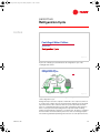
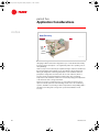
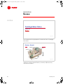
Preface
Centrifugal Water Chillers
A Trane Air Conditioning Clinic
Figure 1
The Trane Company believes that it is incumbent on manufacturers to serve the
industry by regularly disseminating information gathered through laboratory
research, testing programs, and field experience.
The Trane Air Conditioning Clinic series is one means of knowledge sharing.
It’s intended to acquaint a nontechnical audience with various fundamental
aspects of heating, ventilating, and air conditioning.
We’ve taken special care to make the clinic as uncommercial and
straightforward as possible. Illustrations of Trane products only appear in
cases where they help convey the message contained in the accompanying
text.
This particular clinic introduces the concept of centrifugal water chillers.
ii
© 1999 American Standard Inc. All rights reserved
TRG-TRC010-EN
trgtrc010_book.book Page iii Wednesday, September 1, 1999 10:39 AM
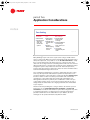
Contents
Introduction ........................................................... 1
period one
Components .......................................................... 3
Compressor ............................................................ 4
Condenser .............................................................. 7
Expansion Device .................................................... 8
Economizer ............................................................. 9
Evaporator ............................................................ 11
Motor ................................................................... 12
Controls and Starter .............................................. 13
period two
Refrigeration Cycle ............................................ 15
Refrigerants .......................................................... 19
Purge System ....................................................... 20
period three Compressor Capacity Control ........................ 22
period four
Maintenance Considerations .......................... 30
period five
Application Considerations ............................. 36
Condensing Temperature Control .......................... 37
Constant or Variable Evaporator Water Flow .......... 39
Short Evaporator-Water Loops ............................... 40
Heat Recovery ...................................................... 42
Free Cooling .......................................................... 44
Equipment Certification Standards ......................... 46
period six
Review ................................................................... 48
Quiz ......................................................................... 52
Answers ................................................................ 54
Glossary ................................................................ 55
TRG-TRC010-EN
iii
trgtrc010_book.book Page iv Wednesday, September 1, 1999 10:39 AM
iv
TRG-TRC010-EN
trgtrc010_book.book Page 1 Wednesday, September 1, 1999 10:39 AM
Introduction
notes
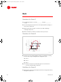
Chilled
Water
System
Figure 2
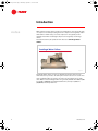
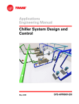
Water chillers are used in a variety of air conditioning and process cooling
applications. They are used to make cold water that can be transported
throughout a facility using pumps and pipes. This cold water can be passed
through the tubes of coils to cool the air in an air conditioning application, or it
can provide cooling for a manufacturing or industrial process.
Systems that employ water chillers are commonly called chilled water
systems.
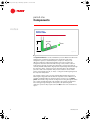
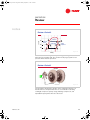
centrifugal
absorption
helical-rotary
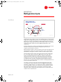
Figure 3
There are several types of water chillers. They differ from each other based on
the refrigeration cycle or the type of compressor they use.
Absorption water chillers make use of the absorption refrigeration cycle and do
not have a mechanical compressor involved in the refrigeration cycle.
TRG-TRC010-EN
1
trgtrc010_book.book Page 2 Wednesday, September 1, 1999 10:39 AM
Introduction
notes
Water chillers using the vapor-compression refrigeration cycle vary by the type
of compressor used. Reciprocating and scroll compressors are typically used in
small chillers. Helical-rotary (or screw) compressors are typically used in
medium-sized chillers. Centrifugal compressors are typically used in large
chillers.
As mentioned earlier, this particular clinic discusses centrifugal water
chillers.
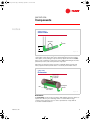
Centrifugal Water Chillers
Figure 4
Centrifugal water chillers can also be divided into two types based on the
method used to reject heat to the atmosphere: water-cooled or air-cooled. Since
most centrifugal chillers are water-cooled, they are the primary focus of this
clinic. Water-cooled centrifugal chillers are generally available from 100 to 3,000
tons [350 to 10,500 kW] as prefabricated machines, and up to 8,500 tons
[30,000 kW] as built-up machines.
2
TRG-TRC010-EN
trgtrc010_book.book Page 3 Wednesday, September 1, 1999 10:39 AM
period one
Components
notes
Centrifugal Water Chillers
period one
Figure 5
Many of the components of the centrifugal water chiller are similar to those of
other chiller types.
components of a
Centrifugal Water Chiller
compressor
motor
condenser
control
panel
evaporator
starter
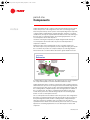
Figure 6
This particular centrifugal water chiller makes use of a shell-and-tube
evaporator where refrigerant absorbs heat from the water flowing through the
tubes. The compressor is made up of 1 or more centrifugal impellers. A second
shell-and-tube heat exchanger serves as the water-cooled condenser, where
refrigerant is condensed inside the shell and water flows inside tubes.
Refrigerant is metered through the system using an expansion device such as a
fixed orifice plate. An economizer can be used to enhance the efficiency of a
chiller with multiple compressor impellers. A control panel is also provided on
the chiller and a starter is either mounted on the chiller or located remotely.
TRG-TRC010-EN
3
trgtrc010_book.book Page 4 Wednesday, September 1, 1999 10:39 AM
period one
Components
notes
Compressor
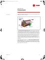
Figure 7
Compressor
The centrifugal compressor uses the principle of dynamic compression,
which involves converting energy from one form to another, to increase the
pressure and temperature of the refrigerant. It converts kinetic energy to static
energy.
Impeller
blades
Figure 8
The core component of a centrifugal compressor is the rotating impeller. The
center, or eye, of the impeller is fitted with blades that draw refrigerant vapor
into radial passages that are internal to the impeller body.
4
TRG-TRC010-EN
trgtrc010_book.book Page 5 Wednesday, September 1, 1999 10:39 AM
period one
Components
notes
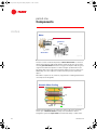
Centrifugal Compressor
volute
diffuser
passage
impeller
passages
Figure 9
The rotation of the impeller causes the refrigerant vapor to accelerate within the
impeller passages, increasing its velocity and kinetic energy.
The accelerated refrigerant vapor leaves the impeller and enters the diffuser
passages. These passages start out small and become larger as the refrigerant
travels through them. As the size of the diffuser passages increases, the
velocity, and therefore the kinetic energy, of the refrigerant decreases.
The first law of thermodynamics states that energy is not destroyed—only
converted from one form to another. Thus, the refrigerant’s kinetic energy is
converted to static energy or static pressure.
Refrigerant, now at a higher pressure, collects in a larger space around the
perimeter of the compressor called the volute. The volute also becomes larger
as the refrigerant travels through it. Again, as the size of the volute increases,
the kinetic energy is converted to static pressure.
Due to its pressure and temperature, the refrigerant leaving the compressor is
in a condition that allows its heat to be rejected from the chiller.
TRG-TRC010-EN
5
trgtrc010_book.book Page 6 Wednesday, September 1, 1999 10:39 AM
period one
Components
notes
centrifugal compressor
Energy Conversion
static pressure
velocity
refrigerant
enters
diffuser
refrigerant
enters impeller
path through compressor
refrigerant
enters volute
Figure 10
Again, in the passages of the rotating impeller, the refrigerant vapor
accelerates, increasing its velocity and kinetic energy. As the area increases in
the diffuser passages, the velocity, and therefore the kinetic energy, of the
refrigerant decreases. This reduction in kinetic energy is offset by an increase in
the refrigerant’s static energy or static pressure. Finally, the high pressure
refrigerant collects in the volute around the perimeter of the compressor, where
further energy conversion takes place.
The resulting pressure and temperature of the refrigerant is now high enough
that its heat can be rejected from the chiller.
Multistage Compressor
Figure 11
Centrifugal compressors use 1 or more impellers to compress the refrigerant. A
multistage compressor uses 2 or 3 impellers to increase the pressure of the
refrigerant in steps instead of performing the task within a single impeller.
Compressed refrigerant vapor travels from the outlet of the first-stage
compressor impeller to the inlet of the second-stage compressor impeller. After
6
TRG-TRC010-EN
trgtrc010_book.book Page 7 Wednesday, September 1, 1999 10:39 AM
period one
Components
notes
the accelerated refrigerant vapor leaves the last impeller, it collects in the
compressor volute and travels on to the condenser.
Condenser
refrigerant vapor
baffle
cooling
tower
water
tube
bundle
liquid
refrigerant
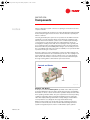
Figure 12
Condenser
The high-pressure refrigerant vapor is discharged from the compressor into a
heat exchanger that acts as a condenser.
In a water-cooled condenser, water is pumped through the tubes of the shelland-tube heat exchanger while refrigerant vapor fills the shell space
surrounding the tube bundle. A baffle inside the condenser helps distribute the
refrigerant evenly. As heat transfers from the hot, high-pressure refrigerant
vapor to the water, refrigerant condenses on the tube surfaces.
Cooling water flows first through the lower tubes and then through the upper
tubes. This produces a nearly constant temperature difference between the
downward-moving refrigerant and the tube surfaces, resulting in a uniform
heat transfer rate within the tube bundle.
Condensed liquid refrigerant collects in the bottom of the shell and flows
through the liquid line to the expansion devices and economizer.
TRG-TRC010-EN
7
trgtrc010_book.book Page 8 Wednesday, September 1, 1999 10:39 AM
period one
Components
notes
expansion device
Orifice Plates
orifice plates
to
evaporator
H1
Figure 13
Expansion Device
An expansion device is used to maintain the pressure difference between the
high-pressure (condenser) and low-pressure (evaporator) sides of the
refrigeration system, as established by the compressor. This pressure
difference allows the evaporator temperature to be low enough for the
refrigerant to absorb heat from the water being cooled, and the condenser
temperature to be high enough for the refrigerant to reject heat to water at
normally available temperatures. High-pressure liquid refrigerant flows through
the expansion device, causing a pressure drop that reduces the refrigerant
pressure to that of the evaporator. This pressure reduction causes a small
portion of the liquid to boil off, or “flash,” cooling the remaining refrigerant to
the evaporator temperature.
The expansion device is also used as a liquid refrigerant metering system,
balancing the refrigerant flow rate with the evaporator load condition. In our
example centrifugal chiller, the expansion device used is a set of 2 orifice
plates. At full load, a large amount of refrigerant is moving through the chiller.
The column of liquid refrigerant in the liquid line pressurizes the liquid at its
base. During passage through the orifice plates, the liquid refrigerant
undergoes a pressure drop equal to the head (H1) before some of it flashes to
vapor.
8
TRG-TRC010-EN
trgtrc010_book.book Page 9 Wednesday, September 1, 1999 10:39 AM
period one
Components
notes
expansion device
Orifice Plates
orifice plates
to
evaporator
H2
Figure 14
As the load decreases, less refrigerant moves through the chiller and the level
of the liquid column drops. Now, as the liquid refrigerant passes through the
orifice plates, it only undergoes a pressure drop equal to the lower head (H2)
before some of it flashes to vapor. This causes additional flashing at the orifice
plate which, in turn, feeds less liquid to the evaporator.
Other types of expansion devices found in centrifugal chillers include: float
valves, expansion valves (thermostatic or electronic), and variable orifices.
2-stage chiller
Economizer
refrigerant vapor
to second stage
of compression
orifice
liquid refrigerant
from condenser
liquid refrigerant
to evaporator
Figure 15
Economizer
An economizer can be used in conjunction with multiple expansion devices to
improve the efficiency of a multistage chiller. In a chiller with a 2-stage
compressor, the expansion process can be separated into 2 steps with an
economizer chamber between.
TRG-TRC010-EN
9
trgtrc010_book.book Page 10 Wednesday, September 1, 1999 10:39 AM
period one
Components
notes
Liquid refrigerant from the condenser enters the first expansion device, which
reduces the pressure of the refrigerant to that of the second-stage impeller
inlet. This pressure drop causes a portion of the liquid refrigerant to evaporate,
or flash, and the resulting mixture of liquid and vapor enters the economizer
chamber. Here, the vapor is separated from the mixture and is routed directly to
the inlet of the second stage impeller. The remaining liquid travels on to the
second expansion device and evaporator.
Just before entering the evaporator, the liquid refrigerant flows through a
second expansion device that reduces its pressure and temperature to
evaporator conditions.
Flashing a portion of the refrigerant prior to the economizer reduces the
amount of compressor power required, since the refrigerant vapor generated in
the economizer only needs to be compressed by the second-stage impeller.
The benefit of the economizer will be discussed in greater detail in Period 2.
3-stage chiller
Economizer
refrigerant vapor
to third stage
of compression
refrigerant vapor
to second stage
of compression
liquid refrigerant
to evaporator
orifice
liquid refrigerant
from condenser
orifice
Figure 16
In a chiller with a 3-stage compressor, the expansion process can be separated
into 3 steps with separate economizer chambers between the steps.
Liquid refrigerant from the condenser enters the first orifice (expansion device),
which reduces the pressure of the refrigerant to that of the third-stage impeller
inlet. This pressure drop causes a portion of the liquid refrigerant to flash, and
the resulting mixture of liquid and vapor enters the high-pressure chamber of
the economizer. Here, the vapor is separated from the mixture and is then
routed directly to the inlet of the third-stage impeller. The remaining liquid
travels on to the second expansion device.
The second expansion device further reduces the pressure of the refrigerant to
that of the second-stage impeller inlet. This pressure drop causes a portion of
the liquid refrigerant to flash, and the resulting mixture of liquid and vapor
enters the low-pressure chamber of the economizer. Here, the vapor is
separated from the mixture and routed directly to the inlet of the second-stage
impeller. The remaining liquid travels on to the third expansion device and
evaporator.
10
TRG-TRC010-EN
trgtrc010_book.book Page 11 Wednesday, September 1, 1999 10:39 AM
period one
Components
notes
Again, the final expansion device reduces the pressure and temperature of the
refrigerant to evaporator conditions.
Evaporator
tube bundle
liquid
refrigerant
chilled
water
return
liquid
distributor
eliminator
orifice system
Figure 17
Evaporator
In the flooded shell-and-tube evaporator shown, the low-pressure mixture
of liquid refrigerant and refrigerant vapor enters the distribution system that
runs the entire length of the shell. Small openings and baffles in the passage of
the liquid distributor provide an even spray of refrigerant over the surfaces of
the tubes inside the evaporator shell, where the refrigerant absorbs heat from
relatively warm water flowing through the tube bundle. This transfer of heat
boils the liquid refrigerant on the tube surfaces. The resulting vapor passes
through an eliminator that prevents liquid from being drawn upward. The vapor
collects in a large chamber at the top of the shell and is drawn back to the
compressor. The now-cool water can be used in a variety of comfort or process
applications.
Some chiller designs may make use of a direct expansion (DX) shell-andtube evaporator. In this type of evaporator, liquid refrigerant flows through
the tubes and water fills the surrounding shell. As heat is transferred from the
water to the refrigerant, the refrigerant boils inside the tubes and the resulting
vapor is drawn to the compressor.
TRG-TRC010-EN
11
trgtrc010_book.book Page 12 Wednesday, September 1, 1999 10:39 AM
period one
Components
notes
Motor
motor
gear-drive
impeller
motor
impellers
direct-drive
gears
Figure 18
Motor
A motor is used to rotate the impeller(s). A direct-drive motor is connected
directly to the impeller shaft and the impeller rotates at the same speed as the
motor. A gear-drive motor transfers its energy to the impeller shaft using a set
of gears. This allows the impeller to rotate at a higher speed than the motor.
The direct-drive motor requires fewer bearings and does not incur gear losses.
Additionally, since the compressor rotates at a lower speed, it can be much
quieter.
Direct-drive compressors are, however, only practical in centrifugal chillers that
use low-pressure refrigerants.
Hermetic Motor Cooling
stator
rotor
liquid
refrigerant
drain
Figure 19
Another important difference in compressor motors is the issue of hermetic
versus open. A hermetic motor is totally enclosed within the chiller’s
refrigeration system. An open motor is mounted externally—outside of the
12
TRG-TRC010-EN
trgtrc010_book.book Page 13 Wednesday, September 1, 1999 10:39 AM
period one
Components
notes
chiller’s refrigeration system—and uses a coupling to connect the motor and
compressor shafts.
The heat generated by the hermetic motor is absorbed by liquid refrigerant that
flows around, through, and over the motor. The heat must be rejected by the
chiller’s condenser.
The heat generated by the open motor is rejected to the air drawn in from the
equipment room. This heat must still be rejected from the equipment room,
either by mechanical ventilation or, if the room is conditioned, the building’s
cooling system. In some designs, this air is simply drawn into the motor
housing by the rotating motor shaft. The vent passages tend to get dirty and
clog, resulting in higher operating temperatures and hot spots that adversely
affect motor efficiency and reliability. Other designs, such as totally-enclosed
fan-cooled (TEFC) and totally-enclosed air-over (TEAO), use a separate fan with
a protective housing to cool the motor.
Hermetic compressor motors eliminate the need for the shaft couplings and
external shaft seals that are associated with open motors. The coupling needs
precise alignment, and these seals are a prime source of oil and refrigerant
leaks. On the other hand, if a motor burns out, a hermetic chiller will require
thorough cleaning, while a chiller with an open motor will not.
Controls and Starter
control
panel
starter
Figure 20
Controls and Starter
A microprocessor-based control panel is provided on the chiller to provide
accurate chilled-water control as well as monitoring, protection, and adaptive
limit functions. These controls monitor chiller operation and prevent the chiller
from operating outside its limits. They can compensate for unusual operating
conditions, keeping the chiller running by modulating system components
rather than simply shutting it down when a safety setting is violated. When
serious problems occur, diagnostic messages aid troubleshooting.
Modern control systems not only provide accurate, optimized control and
protection for the chiller, but can also interface with a building automation
system for integrated system control. In a chilled water system, optimal
TRG-TRC010-EN
13
trgtrc010_book.book Page 14 Wednesday, September 1, 1999 10:39 AM
period one
Components
notes
performance is a system-wide issue, not just a matter of chiller design and
control.
A starter links the chiller motor and the electrical distribution system. Its
primary function is to connect (start) and disconnect (stop) the chiller from line
power—similar to what a switch does for a light bulb. The starter, however,
handles much more current and must have the appropriate interlocks to work
with the chiller control panel and oil pump.
Every electrically driven chiller requires a starter. It must be compatible with the
characteristics of both the compressor motor and the electrical circuitry of the
chiller. There are many types of starters, including star-delta, across-the-line,
auto-transformer, primary reactor, and solid state. A variable-speed drive,
which is used to modulate the speed of the motor during normal operation,
also serves as a starter. Important characteristics to consider when selecting a
starter include first cost, reliability, line voltage, and available current.
Starters
line power
line power
control power
wiring
starter
control power
wiring
unit-mounted
remote-mounted
Figure 21
The starter may be mounted on, or remotely from, the chiller. Use of a unitmounted starter reduces electrical installation costs. It may also improve
reliability and save system design time, since all of the components are preengineered and factory mounted.
Depending on the type of starter selected, there are several options that can
simplify installation. Disconnects allow the starter to be isolated from the
electrical distribution system, and short-circuit protection can be provided
using fuses or a circuit breaker.
14
TRG-TRC010-EN
trgtrc010_book.book Page 15 Wednesday, September 1, 1999 10:39 AM
period two
Refrigeration Cycle
notes
Centrifugal Water Chillers
period two
Figure 22
A pressure–enthalpy (p-h) chart illustrates the refrigeration cycle of the
centrifugal water chiller.
2-stage centrifugal chiller
Refrigeration Cycle
2-stage
compressor
economizer
condenser
evaporator
expansion devices
Figure 23
First, let’s review the components of a 2-stage centrifugal chiller in the context
of the refrigeration cycle.
Refrigerant vapor leaves the evaporator and flows to the compressor, where it
is compressed to a higher pressure and temperature. High-pressure refrigerant
vapor then travels to the condenser where it rejects heat to water, and then
leaves as a saturated liquid. The pressure drop created by the first expansion
device causes part of the liquid refrigerant to evaporate and the resulting
mixture of liquid and vapor enters the economizer. Here, the vapor is separated
from the mixture and routed directly to the inlet of the second-stage impeller.
The remaining saturated liquid refrigerant enters the second expansion device.
TRG-TRC010-EN
15
trgtrc010_book.book Page 16 Wednesday, September 1, 1999 10:39 AM
period two
Refrigeration Cycle
notes
The pressure drop created by the second expansion device lowers the pressure
and temperature of the refrigerant to evaporator conditions, causing a portion
of the liquid refrigerant to evaporate. The resulting mixture of liquid and vapor
enters the evaporator. In the evaporator, the liquid refrigerant boils as it absorbs
heat from water and the resulting vapor is drawn back to the compressor to
repeat the cycle.
pressure
Pressure-Enthalpy (p-h) Chart
5 psia
subcooled
liquid
mixture of
liquid and
vapor
%
$
[0.034 MPa]
MPa]
superheated
vapor
15.5 Btu/lb
Btu/lb
92.4 Btu/lb
Btu/lb
[201.0 kJ/kg]
[380.4 kJ/kg]
enthalpy
Figure 24
The pressure-enthalpy chart plots the properties of a refrigerant—refrigerant
pressure (vertical axis) versus enthalpy (horizontal axis). Enthalpy is a
measure of the heat content, both sensible and latent, per pound [kg] of
refrigerant.
For example, A represents the heat content of saturated liquid HCFC-123
refrigerant at 5 psia [0.034 MPa] and 34°F [1.1°C]. B represents the heat content
of saturated vapor HCFC-123 refrigerant at the same pressure and temperature.
The difference in heat content, or enthalpy, between A and B—that is, 76.9 Btu/
pound [179.4 kJ/kg]—is the amount of heat required to transform 1 pound of
saturated liquid refrigerant to saturated refrigerant vapor at the same pressure
and temperature.
If the heat content of the refrigerant at any pressure falls to the right of the
curve, the vapor is superheated. Similarly, if the heat content of the refrigerant
falls to the left of the curve, the liquid is subcooled. Finally, when the heat
content of the refrigerant falls inside the curve, the refrigerant exists as a
mixture of liquid and vapor.
Let’s plot the theoretical vapor-compression refrigeration cycle for a 2-stage
centrifugal water chiller on a pressure-enthalpy chart.
16
TRG-TRC010-EN
trgtrc010_book.book Page 17 Wednesday, September 1, 1999 10:39 AM
period two
Refrigeration Cycle
notes
2-stage centrifugal chiller
pressure
Refrigeration Cycle
Pc
P1
Pe
condenser
6
expansion
devices
8
9
4
economizer 5
7
evaporator
enthalpy
2-stage
2 compressor
3
1
Figure 25
Refrigerant leaves the evaporator as saturated vapor ➀ and flows to the firststage impeller of the compressor. There, the refrigerant vapor is compressed to
a higher pressure (P1) and temperature ➁. Cooler refrigerant vapor that flashed
within the economizer is mixed with the refrigerant discharged from the firststage impeller, reducing the heat content of the mixture ➂. The second stage of
compression further elevates the pressure (Pc) and temperature of the
refrigerant ➃.
Energy provided to the compressor is imparted to the refrigerant as an increase
in pressure and superheat. Superheated refrigerant vapor leaves the
compressor and enters the condenser.
Water flowing through the condenser absorbs heat from the hot, high-pressure
refrigerant vapor, causing it to desuperheat ➄ and condense into saturated
liquid ➅ before leaving the condenser to travel to the first expansion device.
The first expansion device reduces the pressure (➅ to ➆) of the refrigerant to
the second-stage impeller inlet pressure (P1). This pressure drop causes a
portion of the liquid refrigerant to evaporate, or flash. The evaporating
refrigerant absorbs heat from the remaining liquid refrigerant, reducing its
enthalpy from ➆ to ➇. The resulting mixture of liquid and vapor enters the
economizer ➆. Here, the vapor is separated from the mixture and routed
directly to the second-stage impeller inlet ➂ and the remaining liquid travels on
to the second expansion device ➇.
Just before it enters the evaporator, the liquid refrigerant flows through a
second expansion device that reduces its pressure (Pe) and temperature to
evaporator conditions ➈. The cool, low-pressure mixture of liquid and vapor
enters the distribution system in the evaporator shell and absorbs heat from
water that flows through the tubes. This transfer of heat boils the liquid
refrigerant, and the resulting saturated refrigerant vapor is drawn back to the
compressor ➀ to repeat the cycle.
TRG-TRC010-EN
17
trgtrc010_book.book Page 18 Wednesday, September 1, 1999 10:39 AM
period two
Refrigeration Cycle
notes
2-stage centrifugal chiller
pressure
Refrigeration Cycle
Pc
P1
Pe
condenser
6
expansion
devices
8
4
economizer 5
7
2-stage
2 compressor
3
10
9
1
evaporator
& % enthalpy
$
Figure 26
The change in enthalpy from C to A that occurs during the refrigeration cycle is
called the refrigeration effect. This is the amount of heat that each pound
[kg] of liquid refrigerant will absorb when it evaporates.
The benefit of the economizer can be demonstrated by comparing the
refrigeration cycles with and without an economizer.
Without an economizer, refrigerant from the condenser ➅ expands directly to
evaporator conditions ➉, producing a smaller refrigeration effect (B to A).
Some chiller designs may subcool the liquid refrigerant in the condenser (➅
moves to the left) to increase this refrigeration effect.
Also, in a chiller without an economizer, all of the refrigerant vapor must go
through both stages of compression to return to condensing conditions. In a
chiller with an economizer, refrigerant vapor that flashes in the economizer
bypasses the first stage of compression, resulting in an overall energy savings
of 3 to 4 percent.
18
TRG-TRC010-EN
trgtrc010_book.book Page 19 Wednesday, September 1, 1999 10:39 AM
period two
Refrigeration Cycle
notes
Refrigerant Operating Pressures
HCFC-22
pressure
HFC-134a
HCFC-123
atmospheric
pressure
temperature
Figure 27
Refrigerants
When selecting which refrigerant to use in a centrifugal water chiller, the
manufacturer considers efficiency, operating pressures, compatibility with
materials, heat transfer properties, stability, toxicity, flammability, cost,
availability, and environmental impact.
Refrigerants commonly used in centrifugal chillers can be classified as low,
medium, or high pressure based on the normal operating pressures in the
refrigeration cycle.
Chillers using a high-pressure refrigerant like HCFC-22, or a medium-pressure
refrigerant like HFC-134a, operate at pressures that are well above atmospheric
pressure. As we are about to see, some sections of chillers that use a lowpressure refrigerant such as HCFC-123 operate at below-atmospheric pressure.
TRG-TRC010-EN
19
trgtrc010_book.book Page 23 Wednesday, September 1, 1999 10:39 AM
period three
Compressor Capacity Control
notes
Multistage Compressor
impellers
inlet vanes
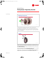
Figure 33
In a multistage centrifugal compressor, the operating characteristics of
each impeller are modulated by the impeller’s own set of inlet vanes.
This example shows 2 impellers in series. These impellers share the task of
compressing the refrigerant. Centrifugal water chillers are generally available
with 1, 2, or 3 impellers.
Impeller
R
Vr
Vt
Figure 34
The forces that act on the refrigerant vapor within the centrifugal compressor
impeller can be broken down into 2 components. One component acts to move
the refrigerant away from the impeller in a radial direction. This component is
called radial velocity (Vr).
The second component acts to move the refrigerant in the direction of impeller
rotation. This component is called tangential velocity (Vt).
Together, these components generate the resultant velocity vector (R), the
length of which is proportional to the amount of kinetic energy in the
TRG-TRC010-EN
23
trgtrc010_book.book Page 24 Wednesday, September 1, 1999 10:39 AM
period three
Compressor Capacity Control
notes
refrigerant. Recall that kinetic energy is converted to static energy, or static
pressure.
Impeller Dynamics
Vr ∝ refrigerant flow rate
R
Vr
Vt ∝ rotational speed × diameter
Vt
diameter
rotational
speed
refrigerant
flow rate
Figure 35
The radial velocity (Vr) for a given compressor is directly proportional (∝) to the
flow rate of refrigerant vapor through the compressor.
The tangential velocity (Vt) is proportional to the product of impeller rotational
speed and impeller diameter.
Therefore, the static-pressure-producing capacity of a compressor can be
adjusted by changing the flow rate of refrigerant, the impeller speed, or the
diameter of the impeller.
24
TRG-TRC010-EN
trgtrc010_book.book Page 25 Wednesday, September 1, 1999 10:39 AM
period three
Compressor Capacity Control
notes
Compressor Unloading
R
Vr
R
Vt
Vt
full load
part load
Vr
Figure 36
Consider a given-diameter compressor impeller that rotates at a constant
speed. As the load on the chiller decreases, the inlet vanes partially close and
the flow rate of refrigerant through the compressor drops. Radial velocity (Vr),
which is proportional to refrigerant flow, decreases as well.
Even though the speed of rotation and diameter of the impeller are constant,
the tangential velocity (Vt) (which is proportional to the product of impeller
rotational speed and impeller diameter) drops because of the pre-swirling of
the refrigerant caused by the inlet vanes.
The result is a shorter resultant velocity vector (R), which means that less static
pressure is generated.
TRG-TRC010-EN
25
trgtrc010_book.book Page 26 Wednesday, September 1, 1999 10:39 AM
period three
Compressor Capacity Control
notes
Surge
Vr
R
Vr < static pressure
Vt
Figure 37
As the load and the corresponding refrigerant flow rate continue to fall, the
radial velocity (force) drops, too. At some point, the radial force becomes
smaller than the generated static pressure, letting the pressurized refrigerant
vapor flow backward from the diffuser passages into the impeller. This
instantaneously reduces the pressure within the passages below the radial
force and the compressor is able to re-establish the proper direction of
refrigerant flow.
This condition is known as surge. So long as this unstable load condition
exists, the refrigerant alternately flows backward and forward through the
compressor impeller, generating noise and vibration.
pressure difference
Compressor Map
r ge
su
90
75
51
10
14
25
36
refrigerant flow rate
63
vane position
(degrees)
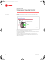
Figure 38
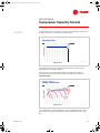
These curves represent the performance of a typical 2-stage compressor over a
range of inlet vane positions. The pressure difference between the compressor
inlet (evaporator) and outlet (condenser) is on the vertical axis and the
refrigerant flow rate is on the horizontal axis. The dashed line represents the
26
TRG-TRC010-EN
trgtrc010_book.book Page 27 Wednesday, September 1, 1999 10:39 AM
period three
Compressor Capacity Control
notes
conditions that cause the compressor to surge. Any operating point that falls to
the right of this line is satisfactory for stable operation.
Operating Point
pressure difference
operating
point
Figure 39
refrigerant flow rate
To balance the load on the chiller, the compressor must pump a certain quantity
of refrigerant vapor at evaporator pressure and elevate it to the pressure
dictated by the condensing conditions.
The intersection of the refrigerant flow rate and the pressure difference
between the inlet and outlet of the compressor identifies the compressor
operating point.
compressor map for a
2-Stage Compressor
pressure difference
operating
point
r ge
su
90
75
51
10
14
25
63
36
refrigerant flow rate
vane position
(degrees)
Figure 40
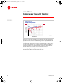
Superimposing the operating point on the previous compressor performance
curves establishes the point at which the compressor will balance the load. In
this example, the compressor will balance the load with its inlet vanes open
90°.
TRG-TRC010-EN
27
trgtrc010_book.book Page 28 Wednesday, September 1, 1999 10:39 AM
period three
Compressor Capacity Control
notes
compressor map for a
2-Stage Compressor
pressure difference
$
r ge
su
90
%
&
75
51
10
14
25
63
36
unloading line
refrigerant flow rate
Figure 41
The starting point (A) is the full-load operating point. As the load on the chiller
decreases, the inlet vanes partially close, reducing the flow rate of refrigerant
vapor through the compressor and balancing the chiller capacity with the new
load (B).
Less refrigerant, and therefore less heat, is transferred to the condenser. Since
the heat rejection capacity of the condenser is now greater than required, the
refrigerant condenses at a lower temperature and pressure. This reduces the
pressure difference between the evaporator and the condenser.
Continuing along the unloading line, the compressor remains within its stable
operating range until it reaches the surge region at C.
28
TRG-TRC010-EN
trgtrc010_book.book Page 29 Wednesday, September 1, 1999 10:39 AM
period three
Compressor Capacity Control
notes
power consumption
Adjustable-Frequency Drives
inlet vanes only
AFD + inlet vanes
load
Figure 42
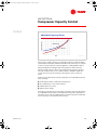
An adjustable-frequency drive (AFD), or variable-speed drive, is another
device used to vary the capacity of a centrifugal compressor. AFDs are widely
used with fans and pumps, and with the advancement of microprocessor-based
controls for chillers, they are now being applied to centrifugal water chillers.
Using an AFD with a centrifugal chiller can degrade the chiller’s full-load
efficiency. It will, however, offer energy savings by reducing motor speed at
low-load conditions when cooler condenser water is available. An AFD also
controls the inrush current at start-up, reducing stress on the compressor
motor.
Certain system characteristics favor the application of an adjustable frequency
drive, including:
■
A substantial number of part-load operating hours
■
The availability of cooler condenser water
■
Chilled-water reset control
■
High electrical charges
Performing a comprehensive energy analysis is the best method of determining
if an adjustable-frequency drive is desirable. Depending on the application, it
may make sense to take the additional money needed to purchase an AFD and
use it to purchase a more efficient chiller instead.
TRG-TRC010-EN
29
trgtrc010_book.book Page 30 Wednesday, September 1, 1999 10:42 AM
period four
Maintenance Considerations
notes
Centrifugal Water Chillers
period four
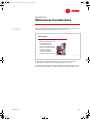
Figure 43
This period discusses general maintenance requirements of centrifugal water
chillers. Although some of the information applies specifically to the design
presented in this clinic, requirements for other centrifugal chiller designs are
also included.
Maintenance Considerations
▲
Operating log
▲
Mechanical components
▲
Heat-transfer surfaces
▲
Fluid analysis
Figure 44
Once a centrifugal chiller is installed and put into operation, it usually continues
to function without a full-time attendant. In many cases, the machine starts and
stops on a schedule controlled by a building automation system or a simple
time clock. The only daily maintenance requirement is to complete and review
the operating log.
Water chillers are designed for maximum reliability with a minimum amount of
maintenance. Like all large mechanical systems, however, certain routine
maintenance procedures are either required or recommended.
30
TRG-TRC010-EN
trgtrc010_book.book Page 31 Wednesday, September 1, 1999 10:42 AM
period four
Maintenance Considerations
notes
operating log
ASHRAE Guideline 3
▲
Chilled water inlet and outlet
temperatures and pressures
▲
Oil pressures, temperature, and
levels
▲
Chilled water flow
▲
Addition of refrigerant
▲
Evaporator refrigerant
temperature and pressures
▲
Addition of oil
▲
Vibration levels
▲
Evaporator approach
temperature
▲
Condenser water inlet and
outlet temperatures and
pressures
▲
Condenser water flow
▲
Condenser refrigerant
temperature and pressures
▲
Condenser approach
temperature
Figure 45
Guideline 3, “Reducing Emission of Halogenated Refrigerants in Refrigeration
and Air Conditioning Equipment and Systems,” is one of several advisory
documents published by the American Society of Heating, Refrigerating and
Air-Conditioning Engineers (ASHRAE). This guideline includes a list of
recommended data points to be logged daily for each chiller. Much of this data
may be available from the display on the chiller control panel.
Special attention should be given to:
TRG-TRC010-EN
■
Reviewing the operating log and trends
■
Observing the oil pressure drop to determine if the oil filter needs to be
replaced
■
Monitoring evaporator and condenser approach temperatures
■
Observing and recording the oil level
■
Monitoring purge pump-out operation
31
trgtrc010_book.book Page 32 Wednesday, September 1, 1999 10:42 AM
period four
Maintenance Considerations
notes
maintenance considerations
Mechanical Components
▲
▲
Required maintenance
◆
Compressor and motor: no maintenance required
◆
Controls: no maintenance or calibration required
Recommended maintenance
◆
Visually inspect overall unit
◆
Inspect safety controls and electrical components
◆
Tighten electrical connections
◆
Check for leaks
Figure 46
The compressor/motor assembly in direct-drive, hermetic compressor designs
requires little periodic maintenance. The hermetic motor eliminates the need
for external shaft seals associated with open motors. (These seals are a prime
source of oil and refrigerant leaks and should be inspected on a regular basis.)
Hermetic motor designs also eliminate the annual coupling and seal
inspections, alignment, and shaft seal replacement associated with open
motors.
With the advent of microprocessor-based controls, the control panel and
auxiliary controllers require no recalibration or maintenance. Remotelymounted electronic sensors send information to the unit controller, which can
be connected to a building automation system to communicate information
and allow system-level optimization. These systems can notify the operator
with an alarm or diagnostic message when a problem occurs.
As for any mechanical equipment, a daily visual inspection of the chiller is
recommended to look for oil leaks, condensation, loosened electrical or control
wiring, or signs of corrosion. Special attention should be given to safety
controls and electrical components.
A qualified service technician should check the chiller annually for leaks. The
United States Environmental Protection Agency (EPA) mandates refrigerant
recovery whenever a refrigeration circuit is opened during the normal service of
any air conditioning system.
32
TRG-TRC010-EN
trgtrc010_book.book Page 33 Wednesday, September 1, 1999 10:42 AM
period four
Maintenance Considerations
notes
maintenance considerations
Mechanical Components
▲
Other design-specific requirements
◆
Change oil when oil analysis dictates
◆
Replace oil filter periodically
◆
Replace filter drier periodically
◆
Clean oil strainers annually
◆
Check shaft alignment annually
◆
Check coupling annually
◆
Replace shaft seal every 2 to 4 years
◆
Compressor teardown inspection every 5 to 10 years
Figure 47
Some centrifugal compressor designs do require periodic maintenance of
mechanical system components. This includes oil and refrigerant filter changes,
oil strainer changes, and a compressor inspection.
Open-motor compressor designs require shaft alignment, coupling inspection,
bearing lubrication, and cleaning of the motor windings on a quarterly or
annual basis.
In all cases, strictly follow the maintenance requirements and
recommendations published by the manufacturer.
maintenance considerations
Heat Transfer Surfaces
▲
Recommended maintenance
◆
Use a qualified water treatment
specialist
◆
Clean condenser tubes as
needed
◆
Clean water-side strainers
◆
Test tubes every 3 years
Figure 48
To ensure optimum heat transfer performance, the heat transfer surfaces must
be kept free of scale and sludge. Even a thin deposit of scale can substantially
reduce heat transfer capacity. Engage the services of a qualified water
treatment specialist to determine the level of water treatment required to
remove contaminants from the cooling tower water.
TRG-TRC010-EN
33
trgtrc010_book.book Page 34 Wednesday, September 1, 1999 10:42 AM
period four
Maintenance Considerations
notes
Scale deposits are best removed by chemical means. During this process, the
water-cooled condenser is commonly isolated from the rest of the coolingtower-water circuit by valves, while a pump circulates cleaning solution
through the condenser tubes.
Sludge is removed mechanically. This typically involves removing the water
boxes from the condenser and loosening the deposits with a stiff-bristled
brush. The loosened material is then flushed from the tubes with clear water. As
part of this procedure, the strainers in both the chilled-water and cooling-towerwater circuits should be cleaned every year.
Every 3 years (more frequently in process or critical applications), a qualified
service organization should perform nondestructive inspections of the
evaporator and condenser tubes. The eddy-current tube test is a common
method.
Rarely, problems may arise that cause refrigerant or water leaks. These must be
repaired immediately.
Fluid Analysis
▲
▲
Oil analysis
◆
Conduct annual analysis to verify
system integrity
◆
Measure oil pressure drop to
determine if filter needs changing
◆
Measure charge
Refrigerant charge
◆
Conduct analysis of refrigerant
◆
Inspect purge system
Figure 49
Oil analysis is an important annual maintenance task required for centrifugal
water chillers. It may be conducted more frequently for chillers that run
continuously or more often than normal. This test, performed by a qualified
laboratory, verifies the integrity of the refrigeration system by testing the
concentrations of moisture, acidity, and metal. This analysis can determine
where problems exist or could potentially develop. By taking oil samples on a
regular basis, normal operating trends for the compressor and bearing metals
can be analyzed. Instead of adopting a “change the oil once a year whether it
needs it or not” approach, regular oil analyses can be used to determine proper
oil change intervals and predict major problems before they occur.
Refrigerant analysis measures contamination levels and determines suitability
for continued use. It can also determine if recycled refrigerant is suitable for
reuse. Refrigerant analysis helps extend the life of the existing charge and
ensures that the chiller is operating at peak efficiency.
34
TRG-TRC010-EN
trgtrc010_book.book Page 35 Wednesday, September 1, 1999 10:42 AM
period four
Maintenance Considerations
notes
Regularly logging oil and refrigerant charges, and examining the trends of this
data, can help identify potential problems before they occur.
Oil Analysis
▲
Why perform regular oil analysis?
◆
Helps reduce maintenance costs
◆
Detects problems without
compressor disassembly
◆
Extends service life of oil charge
◆
Reduces environmental problems
related to oil disposal
◆
Helps maintain compressor
efficiency and reliability
◆
Helps lower refrigerant emissions
Figure 50
An oil analysis is a key preventive maintenance measure and should be
conducted at least annually. It will help the compressor last longer while
maintaining chiller efficiency and reducing refrigerant emissions.
A certified chemical laboratory can be contracted to perform the analysis for all
types of compressors. Often the chiller manufacturer can provide this service.
TRG-TRC010-EN
35
trgtrc010_book.book Page 36 Wednesday, September 1, 1999 10:42 AM
period five
Application Considerations
notes
Centrifugal Water Chillers
period five
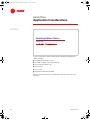
Figure 51
Several considerations must be addressed when applying centrifugal water
chillers, including:
■
Condensing temperature control
■
Constant or variable evaporator-water flow
■
Short evaporator-water loops
■
Heat recovery
■
Free cooling
■
Equipment certification standards
While not all-inclusive, this list of considerations does represent some of the
key issues.
36
TRG-TRC010-EN
trgtrc010_book.book Page 37 Wednesday, September 1, 1999 10:42 AM
period five
Application Considerations
notes
Condensing Temperature Control
$
pressure difference
&
r ge
su
90
75
%
51
10
14
25
63
36
vane position
(degrees)
unloading line
refrigerant flow rate
Figure 52
Condensing Temperature Control
To achieve stable compressor unloading over a wide range of conditions, a
reduction in condensing pressure (condenser relief) must accompany a
reduction in load.
The starting point (A) is the full-load operating point. As the chiller load
decreases, the flow rate of refrigerant vapor through the compressor also
decreases. In turn, the pressure difference between the evaporator and the
condenser moves the operating point downward toward B.
If the condenser pressure had been controlled to a constant value instead, the
compressor would have unloaded along a nearly constant pressure line toward
C. This would result in a greatly reduced range of operation.
Condenser relief is, however, only beneficial to a certain point. ALL chillers
require a minimum pressure difference between the evaporator and condenser
to ensure proper management of oil and refrigerant. This minimum pressure
difference depends on the chiller’s design and controls. The most common
method of maintaining this pressure difference at various load conditions is to
control the condensing temperature by varying the temperature or flow rate of
water through the condenser. By controlling condensing temperature, most
centrifugal water chillers can start and operate over a wide range of conditions.
Controlling condensing temperature: (1) maintains chiller efficiency, (2)
maintains the required pressure differential between the evaporator and
condenser for controlled flow through the refrigerant metering system, and
(3) prevents the pressure imbalance that could cause oil loss problems.
TRG-TRC010-EN
37
trgtrc010_book.book Page 38 Wednesday, September 1, 1999 10:42 AM
period five
Application Considerations
notes
condensing temperature control
Cooling Tower Bypass
40°F
[4°C]
cooling tower
bypass
diverting
valve
65°F
[18°C]
55°F
[13°C]
condenser
Figure 53
Controlling the refrigerant pressure difference between the evaporator and
condenser of a water-cooled chiller is accomplished by varying the temperature
or flow rate of the water flowing through the condenser. The following are 5
common methods used to control condensing temperature:
1) Cycling or varying the speed of the cooling tower fans to control the
temperature of the water leaving the cooling tower
2) Using a cooling tower bypass pipe to mix warmer leaving-condenser water
with the colder tower water and control the temperature entering the condenser
as illustrated here
3) Modulating a throttling valve to restrict the flow of water through the
condenser
4) Using a chiller bypass pipe to vary the flow rate of water through the
condenser
5) Using a variable-speed drive on the condenser water pump to vary the water
flow rate through the condenser
Each of these strategies has its advantages and disadvantages. Selecting the
appropriate condensing temperature control scheme will depend on the
specific requirements of the application.
The water flow rate through the chiller condenser must stay between the
minimum and maximum condenser bundle flow rates specified by the chiller
manufacturer.
38
TRG-TRC010-EN
trgtrc010_book.book Page 39 Wednesday, September 1, 1999 10:42 AM
period five
Application Considerations
notes
evaporator water flow
Constant or Variable Flow
chilled
water
pump
evaporator
variablespeed
drive
Figure 54
Constant or Variable Evaporator Water Flow
Previous chiller designs required that a constant flow rate of water be
maintained through the evaporator. This requirement has changed due to
advances in chiller controls. Increased sensing and control capabilities now
allow chiller manufacturers to design controls that monitor, and respond faster
to, fluctuating conditions.
While the chiller may be able to handle variable water flow through the
evaporator, the specific application of the chilled water system may not warrant
variable flow. As always, each application should be analyzed to determine if
variable evaporator water flow is warranted.
variable evaporator water flow
Limitations
▲
Maintain minimum and maximum water flow
rates through the chiller evaporator
▲
Rate at which the evaporator water flow
changes must be kept below the
corresponding limit to:
◆
Maintain the chilled water set point control
◆
Keep the chiller on line
◆
Protect the chiller from damage
Figure 55
The controls on many current chiller designs can properly control the chiller in
response to varying evaporator flow rates, with the following limitations:
TRG-TRC010-EN
39
trgtrc010_book.book Page 40 Wednesday, September 1, 1999 10:42 AM
period five
Application Considerations
notes
1) The water flow rate through the chiller evaporator must stay between the
minimum and maximum flow rates for the evaporator bundle, as specified by
the chiller manufacturer. These limits depend on the specific design variables of
the actual evaporator bundle such as the number of tubes, number of passes,
and geometry. Implementation of a method for sensing evaporator water flow
through each chiller is the only way to make sure that the water flow rate stays
within these limits.
2) The rate of change for the evaporator water flow rate must not exceed a
specified level, depending on the level of protection desired. For example, the
maximum rate of change to maintain the chilled water set point is more
stringent than the maximum rate of change to keep the chiller on line. There are
3 common levels of protection desired: maintaining chilled water set point
control, keeping the chiller on line, and protecting the chiller from damage.
The limits for these different levels of protection should be obtained from the
chiller manufacturer.
Short Evaporator-Water Loops
load
chilled
water
pump
evaporator
Figure 56
Short Evaporator-Water Loops
Proper chilled water temperature control requires that the temperature of the
chilled water returning to the evaporator not change any faster than the chiller
controls can respond. The volume of water in the evaporator loop acts as a
buffer, ensuring that the return water temperature changes slowly and,
therefore, providing stable temperature control. If there is not a sufficient
volume of water in the loop to provide an adequate buffer, temperature control
can be lost, resulting in erratic system operation.
The chiller manufacturer should be consulted for volume requirements of the
evaporator-water loop.
40
TRG-TRC010-EN
trgtrc010_book.book Page 41 Wednesday, September 1, 1999 10:42 AM
period five
Application Considerations
notes
Short Evaporator-Water Loops
load
tank
chilled
water
pump
evaporator
Figure 57
Short water loops may be unavoidable in close-coupled or very small
applications, particularly in systems where the load consists of only a few air
handlers or processes.
To prevent the effect of a short water loop, a storage tank or large header pipe
can be added to the system to increase the volume of water in the loop and
ensure a slowly changing return water temperature.
A second solution is to reduce the water flow rate in the chilled water loop
while using the same size pipes. This also increases the loop time—the time it
takes a particle of water to travel through the chilled water loop—and ensures
that the return water temperature changes slowly. This solution has the added
benefit of reduced pumping energy requirements.
TRG-TRC010-EN
41
trgtrc010_book.book Page 42 Wednesday, September 1, 1999 10:42 AM
period five
Application Considerations
notes
Heat Recovery
heat-recovery
condenser
cooling
tower
water
standard
condenser
Figure 58
Heat Recovery
Salvaging usable heat from the refrigeration cycle—heat that would normally
be rejected to the atmosphere—can significantly reduce the operating costs of
many buildings.
Heat recovery is most commonly accomplished using 2 condensers and the fact
that hot refrigerant vapor migrates to the area with the lowest temperature.
Raising the refrigerant condensing temperature in the standard condenser
prompts the refrigerant to flow instead to the second condenser, where it
rejects its heat to the water flowing through the tubes. The condensing
temperature in the standard condenser is controlled by varying the temperature
or the flow rate of the cooling tower water.
Typical uses for the hot water from the second condenser include: heat for
spaces around the perimeter of the building, reheat coils in air conditioning
systems, and bathroom, laundry, or kitchen requirements. Any building with a
simultaneous heating and cooling load is a potential candidate for heat
recovery.
42
TRG-TRC010-EN
trgtrc010_book.book Page 43 Wednesday, September 1, 1999 10:42 AM
period five
Application Considerations
notes
Heat-Recovery Chiller Options
heat-recovery
(dual) condenser
auxiliary
condenser
heat pump
◆
Second, fullsize condenser
◆
Second, smaller
size condenser
◆
No extra
condenser
◆
Large heating
loads
◆
Preheating loads
◆
◆
Moderate
hot water
temperatures
Large base heating
loads or continuous
operation
◆
High hot water
temperatures
◆
Controlled
◆
Chiller efficiency
preserved
◆
High hot water
temperatures
◆
Controlled
◆
Uncontrolled
◆
Degrades
chiller efficiency
◆
Improves chiller
efficiency
Figure 59
Three types of heat-recovery chillers are commonly available:
The dual-condenser, or double-bundle, heat-recovery chiller contains a
second, full-size condenser that serves a separate hot water loop. It is capable
of more heat rejection and higher leaving-water temperatures. This type of
chiller allows the amount of heat being rejected to be controlled, although
chiller efficiency is sacrificed for higher hot water temperatures.
Similarly, an auxiliary-condenser heat-recovery chiller makes use of a
second, smaller condenser bundle. It is not capable of rejecting as much heat as
the dual-condenser chiller. Since its leaving-water temperatures are also lower,
it is typically used to preheat returning hot water before it goes to the primary
heating equipment or to preheat incoming water prior to entering a traditional
water heater. It requires no additional controls and actually improves chiller
efficiency.
A heat-pump chiller is a standard chiller (no extra shells are required) applied
where the useful heat transfer occurs in the condenser, not the evaporator. The
evaporator is connected to the chilled water loop, typically upstream of other
chillers, but it only removes enough heat from the chilled water loop to handle
the heating load served by the condenser water loop. This application is useful
in a multiple-chiller installation, where there is a base or year-round comfort or
process load, or where the quantity of heat required is significantly less than
the cooling load. Chiller efficiency is not compromised.
TRG-TRC010-EN
43
trgtrc010_book.book Page 44 Wednesday, September 1, 1999 10:42 AM
period five
Application Considerations
notes
Free Cooling
air-side
economizer
◆
Most efficient
◆
Requires larger
outdoor air,
return, and
exhaust duct
systems
strainer
cycle
◆
Coldest water
temperatures
◆
Potential fouling
in chilled water
loop
◆
Requires
additional piping,
valves, and
controls
plate-and-frame
heat exchanger
◆
Potential fouling
limited to heat
exchanger
◆
Requires additional
heat exchanger,
piping, valves, and
controls
◆
Can operate
simultaneously with
chiller
Figure 60
Free Cooling
Many buildings require some form of year-round cooling to handle interior
spaces or other loads. When the outdoor air temperature falls below the indoor
dew point temperature, it is possible to use an air-side economizer to satisfy
these cooling requirements. This method of “free cooling” involves using
outdoor air for cooling instead of recirculating warmer indoor air. It is the most
efficient method of free cooling because it allows all of the chilled water and/or
refrigeration system components to be turned off. This method, however,
requires larger duct systems to deliver the outdoor air to the air handler and to
return and exhaust this larger amount of air.
A second method of applying free cooling is to pump water from the cooling
tower loop directly into the chilled water loop when its temperature is low
enough to satisfy the cooling load. This is commonly called the strainer cycle
because a strainer or filter is needed to prevent debris and contaminants
carried by the cooling tower water from entering the chilled water loop.
Although this method is very efficient, the contamination common in open
cooling tower systems causes concern about “fouling” (deposits of scale or
sludge) inside the chilled water coils. Ongoing treatment of the chilled water
loop is required.
Another method of providing free cooling is similar to the strainer cycle but
involves the use of a plate-and-frame heat exchanger, or water-side
economizer, to isolate the chilled water loop from the cooling tower loop. This
is a popular method of free cooling because it is efficient and eliminates
potential contamination of the chilled water loop. In addition, the heat
exchanger can be operated simultaneously with the chiller.
44
TRG-TRC010-EN
trgtrc010_book.book Page 45 Wednesday, September 1, 1999 10:42 AM
period five
Application Considerations
notes
free cooling
Refrigerant Migration
from
compressor
condenser
to
compressor
evaporator
Figure 61
This leads to the discussion of a free cooling principle called refrigerant
migration. It involves adapting a water chiller so that it functions as a simple
heat exchanger.
When the available condenser water is cooler than the desired chilled water
temperature, the compressor is turned off and bypass valves in the chiller
refrigerant circuit are opened to let the refrigerant circulate without help from
the compressor. Because refrigerant migrates to the area with the lowest
temperature, refrigerant boils in the evaporator and the vapor flows to the
cooler condenser bundle. After the refrigerant condenses, it flows (by gravity)
back to the evaporator.
The advantages of refrigerant migration are these: no extra components are
required in the system, control is performed by the chiller itself, and there are
no additional fouling concerns. It is possible for the free cooling chiller to satisfy
many cooling load requirements without operating the compressor, especially
when the system can accommodate warmer chilled water temperatures at partload conditions.
TRG-TRC010-EN
45
trgtrc010_book.book Page 46 Wednesday, September 1, 1999 10:42 AM
period five
Application Considerations
notes
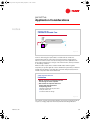
equipment certification standards
ARI Standard 550/590
▲
Purpose
◆
▲
Establish definitions, testing,
and rating requirements
Scope
◆
Factory designed and
prefabricated water chillers
◆
Vapor-compression
refrigeration
◆
Air-cooled and water-cooled
condensing
Figure 62
Equipment Certification Standards
The Air Conditioning & Refrigeration Institute (ARI) establishes rating standards
for packaged HVAC equipment. ARI also certifies and labels equipment through
programs that involve random testing of a manufacturer’s equipment to verify
published performance.
The overall objective of ARI Standard 550/590–1998 is to promote consistent
rating and testing methods for all types and sizes of water chillers, with an
accurate representation of actual performance. It covers factory-designed,
prefabricated water chillers, both air-cooled and water-cooled, using vaporcompression refrigeration. This generally includes chillers with centrifugal,
helical-rotary (screw), reciprocating, or scroll compressors.
equipment certification standards
ARI Standard 550/590
▲
▲
Standard rating conditions
◆
Common system conditions for published ratings
◆
Fouling factor
Integrated Part Load Value (IPLV)
◆
Part-load efficiency rating
◆
Based on an “average” single-chiller installation
◆
Standard operating conditions
Figure 63
The standard rating conditions used for ARI certification represent typical
design temperatures and flow rates for which water-cooled and air-cooled
systems are designed. They are not suggestions for good design practice for a
46
TRG-TRC010-EN
trgtrc010_book.book Page 47 Wednesday, September 1, 1999 10:42 AM
period five
Application Considerations
notes
given system—they simply define a common rating point to aid comparisons.
Trends toward improved humidity control and energy efficiency have changed
some of the actual conditions selected for specific applications.
Impurities in the chilled- and condenser-water systems eventually deposit on
evaporator and condenser tube surfaces, impeding heat transfer. Catalogued
performance data includes a fouling factor that accounts for this effect to more
closely predict actual chiller performance.
ARI’s part-load efficiency rating system establishes a single, blended estimate
of stand-alone chiller performance. The Integrated Part Load Value (IPLV)
predicts chiller efficiency at the ARI standard rating conditions using weighted
averages representing a broad range of geographic locations, building types,
and operating-hour scenarios, both with and without an air-side economizer.
While the weighted averages place greater emphasis on the part-load operation
of an average, single-chiller installation, they will not—by definition—represent
any particular installation.
Additionally, ARI notes that more than 80 percent of all chillers are installed in
multiple-chiller plants. Chillers in these plants exhibit different unloading
characteristics than the IPLV weighted formula indicates. Appendix D of the
Standard explains this further:
...The [IPLV] equation was derived to provide a representation of the
average part-load efficiency for a single chiller only. However, it is best
to use a comprehensive analysis that reflects actual weather data,
building load characteristics, operational hours, economizer
capabilities, and energy drawn by auxiliaries such as pumps and
cooling towers, when calculating the chiller and system efficiency. This
becomes increasingly important with multiple chiller systems because
individual chillers operating within multiple chiller systems are more
heavily loaded than single chillers within single chiller systems.
Remember that the ARI rating is a standardized representation. Many chillers
do not run at standard rating conditions and few are applied in single-chiller
installations. Performing a comprehensive energy analysis is the best method
of comparing the system operating cost difference between 2 chillers.
TRG-TRC010-EN
47
trgtrc010_book.book Page 48 Wednesday, September 1, 1999 10:42 AM
period six
Review
notes
Centrifugal Water Chillers
period six
Figure 64
Let’s review the main concepts that were covered in this clinic on centrifugal
water chillers.
Review—Period 1
compressor
motor
condenser
control
panel
evaporator
starter
Figure 65
Period 1 introduced the following components of a centrifugal water chiller:
compressor, condenser, expansion device, economizer, evaporator, motor,
control panel, and starter.
48
TRG-TRC010-EN
trgtrc010_book.book Page 49 Wednesday, September 1, 1999 10:42 AM
period six
Review
notes
pressure
Review—Period 2
Pc
P1
Pe
condenser
6
expansion
devices
8
2-stage
2 compressor
3
7
9
4
economizer 5
evaporator
1
Figure 66
enthalpy
Period 2 described the refrigeration cycle of 2-stage centrifugal water chillers
with a pressure-enthalpy chart. The operation of the purge system for lowpressure chillers was also presented.
Review—Period 3
impellers
inlet vanes
Figure 67
Period 3 further explained the operation of the centrifugal compressor. It
described the use of impeller inlet vanes as one method for controlling
centrifugal compressor capacity. Surge, multistage compressors, and
adjustable-frequency drives were also discussed.
TRG-TRC010-EN
49
trgtrc010_book.book Page 50 Wednesday, September 1, 1999 10:42 AM
period six
Review
notes
Review—Period 4
▲
Maintenance considerations
◆
Operating log
◆
Mechanical components
◆
Heat-transfer surfaces
◆
Fluid analysis
Figure 68
Period 4 described the general maintenance requirements of a centrifugal water
chiller, including:
■
Recommended data for a daily log
■
Required and recommended maintenance for mechanical components
■
Recommended maintenance for heat transfer surfaces
■
Required analyses for the oil and refrigerant
Review—Period 5
▲
Application considerations
◆
Condensing temperature control
◆
Constant or variable evaporator-water flow
◆
Short evaporator-water loops
◆
Heat recovery
◆
Free cooling
◆
Equipment certification standards
Figure 69
Period 5 presented several considerations in the application of centrifugal water
chillers. These included condensing temperature control for water-cooled
chillers, constant or variable evaporator-water flow, short evaporator-water
loops, heat recovery, free cooling, and equipment certification standards.
50
TRG-TRC010-EN
trgtrc010_book.book Page 51 Wednesday, September 1, 1999 10:42 AM
period six
Review
notes
Figure 70
For more information, refer to the following references:
■
Trane product catalogs for centrifugal water chiller products
(Trane literature order numbers CTV-DS-1 and CTV-DS-2)
■
Condensing Water Temperature Control (CTV-EB-84)
■
Multiple Chiller System Design and Control (CON-AM-21)
■
Principles of Centrifugal Chiller Heat Recovery Operation (AM-REF-2)
■
ARI Standard 550/590–1998: Implications For Chilled-Water Plant Design
(Trane Engineers Newsletter, 1999–volume 28, no. 1)
■
Variable-Primary-Flow Systems (Trane Engineers Newsletter,
■
1999–volume 28, no. 3)
■
Chilled Water Systems Engineered Systems Clinics (CWS-CLC-1, 2, 3, and 4)
■
ASHRAE Handbook—Refrigeration
■
ASHRAE Handbook—Systems and Equipment
Visit the ASHRAE Bookstore at www.ashrae.org.
For information on additional educational materials available from Trane,
contact your local Trane sales office (request a copy of the Educational
Materials price sheet — Trane order no. EM-ADV1) or visit our online bookstore
at www.trane.com/bookstore/.
TRG-TRC010-EN
51
trgtrc010_book.book Page 52 Wednesday, September 1, 1999 10:42 AM
Quiz
Questions for Period 1
1) A centrifugal compressor converts ___________ energy to ____________
energy.
2) Does the refrigerant velocity increase in the impeller, diffuser passages, or
volute of the compressor?
3) What is the benefit of using an economizer cycle with a multistage
centrifugal compressor?
4) What is the difference between a hermetic and an open motor?
Questions for Period 2
pressure
6
4
5
8
7
2
3
1
9
enthalpy
Figure 71
5) Using the pressure-enthalpy diagram in Figure 71, identify the following
process of the 2-stage centrifugal chiller’s refrigeration cycle:
a) ➀ to ➁
b) ➆ to ➂
c) ➈ to ➀
6) Air, moisture, and other noncondensable gases are removed from a
_____-pressure chiller by what component?
Questions for Period 3
7) What velocity component is directly proportional to the refrigerant flow rate
through the compressor?
52
TRG-TRC010-EN
trgtrc010_book.book Page 53 Wednesday, September 1, 1999 10:42 AM
Quiz
8) What velocity component is directly proportional to the impeller’s rotational
speed times its diameter?
9) What are the 2 most common devices used to vary the capacity of a
centrifugal compressor?
Questions for Period 4
10)Explain why proper water treatment is important.
Questions for Period 5
11)The refrigerant migration method of free cooling works because refrigerant
migrates from the area of __________ temperature to the area of __________
temperature.
12)What is the purpose of a fouling factor?
TRG-TRC010-EN
53
trgtrc010_book.book Page 54 Wednesday, September 1, 1999 10:42 AM
Answers
1) kinetic energy to static energy
2) impeller
3) By flashing a portion of the refrigerant prior to entering the evaporator, the
economizer reduces the compressor power required since the refrigerant
vapor generated in the economizer only needs to be compressed by the
higher-stage impeller.
4) A hermetic motor is totally enclosed within the chiller’s refrigeration system
and the heat it generates is absorbed by liquid refrigerant. An open motor is
mounted externally—outside of the chiller’s refrigeration system—and uses
a coupling to connect the motor and compressor shafts. The heat generated
by the open motor is rejected to the air drawn in from the equipment room.
5) a) first stage of compression or first-stage impeller
b) economizer
c) evaporator
6) low-pressure chiller; purge system
7) radial velocity (Vr)
8) tangential velocity (Vt)
9) inlet vanes and adjustable-frequency (or variable-speed) drive
10)The heat transfer (tube) surfaces inside the chiller must be kept free of scale
and sludge to ensure optimum performance. Even a thin deposit of scale
can substantially reduce heat transfer capacity.
11)higher; lower
12)It is used to more closely predict actual chiller performance by accounting
for the effect of impurities in the chilled- and condenser-water systems.
These impurities will eventually deposit on evaporator and condenser tube
surfaces, impeding (fouling) heat transfer.
54
TRG-TRC010-EN
trgtrc010_book.book Page 55 Wednesday, September 1, 1999 10:42 AM
Glossary
adjustable-frequency drive (AFD) A device used to vary the capacity of a
centrifugal compressor by varying the speed of the motor that rotates the
impeller(s).
air-side economizer A method of free cooling that involves using cooler
outdoor air for cooling instead of recirculating warmer indoor air.
ARI Air Conditioning & Refrigeration Institute
ARI Standard 550/590 A publication titled “Standard for Water Chilling
Packages Using the Vapor-Compression Cycle,” used to promote consistent
rating and testing methods for all types and sizes of water chillers. It covers
factory-designed, prefabricated water chillers, both air-cooled and watercooled, using the vapor-compression refrigeration cycle.
ASHRAE American Society of Heating, Refrigerating and Air Conditioning
Engineers
ASHRAE Guideline 3 A publication titled “Reducing Emission of Halogenated
Refrigerants in Refrigeration and Air Conditioning Equipment and Systems,”
that includes a recommended list of data points to be logged daily for each
water chiller.
compressor The mechanical device used by the chiller to increase the
pressure and temperature of the refrigerant vapor.
condenser The region of the chiller where refrigerant vapor is converted to
liquid as it rejects heat to water or air.
control panel The microprocessor-based panel that monitors the chiller’s
operation, protects it from damage, provides the operator with data and
diagnostic messages, and permits interfacing with a building automation
system.
diffuser passages Passages inside the centrifugal compressor that start out
small and become larger as the refrigerant travels through them. As the size of
the diffuser passages increases, the velocity, and therefore the kinetic energy, of
the refrigerant decreases. This kinetic energy is converted to static energy or
static pressure.
direct-drive motor A type of motor that is connected directly to the
compressor shaft, in which the impeller rotates at the same speed as the motor.
direct expansion (DX) shell-and-tube evaporator A type of evaporator where
refrigerant flows through the tubes and water fills the surrounding shell.
dynamic compression A method of compression that involves converting
energy from one form to another to increase the pressure and temperature of
the refrigerant vapor.
TRG-TRC010-EN
55
trgtrc010_book.book Page 56 Wednesday, September 1, 1999 10:42 AM
Glossary
economizer The component of a multistage centrifugal chiller used to remove
vapor from the refrigerant mixture after it passes through an expansion device.
This reduces the compressor power required since the refrigerant vapor
generated in the economizer only needs to be compressed by the higher-stage
impeller(s).
enthalpy The property of a refrigerant indicating its heat content, both
sensible and latent.
evaporator The region of the chiller where the system chilled water is
continuously cooled by boiling the refrigerant as it picks up heat from the
returning system water.
expansion device The component of the chiller used to reduce the pressure
and temperature of the refrigerant.
flash The process of liquid refrigerant being vaporized by a sudden reduction
of pressure.
flooded shell-and-tube evaporator A type of evaporator where water flows
through the tubes and refrigerant fills the surrounding shell.
gear-drive motor A type of motor that transfers its energy to the impeller shaft
using a set of gears, allowing the impeller to rotate at a higher speed than the
motor.
hermetic motor A type of motor that is totally enclosed within the chiller’s
refrigeration system and rejects its heat to the liquid refrigerant.
impeller The rotating component of a centrifugal compressor that draws
refrigerant vapor into its internal passages and accelerates the refrigerant as it
rotates, increasing its velocity and kinetic energy.
inlet vanes A device used to vary the capacity of a centrifugal compressor by
“pre-swirling” the refrigerant in the direction of rotation before it enters the
impeller, lessening its ability to take in the refrigerant vapor.
loop time The amount of time it takes a particle of water to travel through the
chilled water loop.
multistage centrifugal compressor A centrifugal compressor that uses more
than 1 impeller to share the task of compressing the refrigerant.
open motor A type of motor that is mounted externally—outside of the
chiller’s refrigeration system—and uses a coupling to connect the motor and
compressor shafts. It rejects its heat to air drawn in from the equipment room.
orifice plate A type of expansion device that uses a fixed plate with holes
drilled in it to reduce the pressure and temperature of the refrigerant to the
conditions of the evaporator.
56
TRG-TRC010-EN
trgtrc010_book.book Page 57 Wednesday, September 1, 1999 10:42 AM
Glossary
notes
pressure-enthalpy chart A graphical representation of the saturated
properties of a refrigerant, plotting refrigerant pressure versus enthalpy.
purge A device used to remove air, moisture, and other noncondensable
gases that may leak into a low-pressure chiller.
refrigerant migration A method of free cooling that allows the chiller to be
used as a heat exchanger, without operation of the compressor. It is possible,
when the condensing temperature of the refrigerant is low enough, for
refrigerant to migrate from the evaporator to the condenser.
refrigeration effect The amount of heat that each pound [kg] of liquid
refrigerant will absorb when it evaporates.
starter A device used to connect and disconnect the chiller motor and the
electrical distribution system.
surge A condition of unstable compressor operation where the refrigerant
alternately flows backward and forward through the compressor impeller,
generating noise and vibration.
variable-speed drive
See adjustable-frequency drive.
volute A large space around the perimeter of a centrifugal compressor that
collects refrigerant vapor after compression.
water-cooled condenser A type of condenser that rejects the heat of the
refrigerant to water flowing through it.
TRG-TRC010-EN
57
85577_Cover.fm Page 2 Wednesday, September 1, 1999 10:08 AM
The Trane Company
Worldwide Applied Systems Group
3600 Pammel Creek Road
La Crosse, WI 54601-7599
www.trane.com
An American Standard Company
Literature Order Number
TRG-TRC010-EN
File Number
E/AV-FND-TRG-TRC010-999-EN
Supersedes
2803-10-983
Stocking Location
Inland-La Crosse
Since The Trane Company has a policy of continuous product improvement, it reserves the right to change
design and specifications without notice.