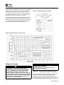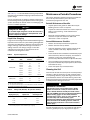
1
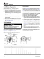
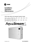
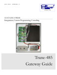
Installation, Operation,
and Maintenance
Air Cooled Condenser
20-60Ton
Models
CCRC020
CCRC035
CCRC060
CIRC020
CIRC035
CIRC060
CCRC025
CCRC040
CCRC030
CCRC050
CIRC025
CIRC040
CIRC030
CIRC050
SAFETY WARNING
Only qualified personnel should install and service the equipment. The installation, starting up, and
servicing of heating, ventilating, and air-conditioning equipment can be hazardous and requires specific
knowledge and training. Improperly installed, adjusted or altered equipment by an unqualified person could
result in death or serious injury. When working on the equipment, observe all precautions in the literature
and on the tags, stickers, and labels that are attached to the equipment.
February 2013
CXRC-SVX01F-EN
Warnings, Cautions and Notices
Warnings, Cautions and Notices. Note that warnings,
cautions and notices appear at appropriate intervals
throughout this manual. Warnings are provide to alert
installing contractors to potential hazards that could result
in death or personal injury. Cautions are designed to alert
personnel to hazardous situations that could result in
personal injury, while notices indicate a situation that
could result in equipment or property-damage-only
accidents.
Your personal safety and the proper operation of this
machine depend upon the strict observance of these
precautions.
Read this manual thoroughly before operating or servicing
this unit.
ATTENTION: Warnings, Cautions and Notices appear at
appropriate sections throughout this literature. Read
these carefully:
Indicates a potentially hazardous
situation which, if not avoided, could
result in death or serious injury.
Indicates a potentially hazardous
CAUTIONs situation which, if not avoided, could
result in minor or moderate injury. It
could also be used to alert against
unsafe practices.
a situation that could result in
NOTICE: Indicates
equipment or property-damage only
WARNING
Important
Environmental Concerns!
Scientific research has shown that certain man-made
chemicals can affect the earth’s naturally occurring
stratospheric ozone layer when released to the
atmosphere. In particular, several of the identified
chemicals that may affect the ozone layer are refrigerants
that contain Chlorine, Fluorine and Carbon (CFCs) and
those containing Hydrogen, Chlorine, Fluorine and
Carbon (HCFCs). Not all refrigerants containing these
compounds have the same potential impact to the
environment.Trane advocates the responsible handling of
all refrigerants-including industry replacements for CFCs
such as HCFCs and HFCs.
must also be adhered to for responsible management of
refrigerants. Know the applicable laws and follow them.
WARNING
Proper Field Wiring and Grounding
Required!
All field wiring MUST be performed by qualified
personnel. Improperly installed and grounded field
wiring poses FIRE and ELECTROCUTION hazards. To
avoid these hazards, you MUST follow requirements for
field wiring installation and grounding as described in
NEC and your local/state electrical codes. Failure to
follow code could result in death or serious injury.
WARNING
Hazardous Voltage w/Capacitors!
Disconnect all electric power, including remote
disconnects and discharge all motor start/run
capacitors before servicing. Follow proper lockout/
tagout procedures to ensure the power cannot be
inadvertently energized. For variable frequency drives or
other energy storing components provided by Trane or
others, refer to the appropriate manufacturer’s literature
for allowable waiting periods for discharge of
capacitors. Verify with an appropriate voltmeter that all
capacitors have discharged. Failure to disconnect power
and discharge capacitors before servicing could result in
death or serious injury.
For additional information regarding the safe discharge
of capacitors, see PROD-SVB06A-EN
WARNING
Personal Protective Equipment (PPE)
Required!
Installing/servicing this unit could result in exposure to
electrical, mechanical and chemical hazards.
•
Before installing/servicing this unit, technicians
MUST put on all Personal Protective Equipment (PPE)
recommended for the work being undertaken.
ALWAYS refer to appropriate MSDS sheets and OSHA
guidelines for proper PPE.
•
When working with or around hazardous chemicals,
ALWAYS refer to the appropriate MSDS sheets and
OSHA guidelines for information on allowable
personal exposure levels, proper respiratory
protection and handling recommendations.
•
If there is a risk of arc or flash, technicians MUST put
on all Personal Protective Equipment (PPE) in
accordance with NFPA 70E or other country-specific
requirements for arc flash protection, PRIOR to
servicing the unit.
Responsible Refrigerant Practices!
Trane believes that responsible refrigerant practices are
important to the environment, our customers, and the air
conditioning industry. All technicians who handle
refrigerants must be certified.The Federal Clean Air Act
(Section 608) sets forth the requirements for handling,
reclaiming, recovering and recycling of certain
refrigerants and the equipment that is used in these
service procedures. In addition, some states or
municipalities may have additional requirements that
© 2013Trane All rights reserved
Failure to follow recommendations could result in death
or serious injury.
CXRC-SVX01F-EN
Warnings, Cautions and Notices
Revision Summary
NOTICE:
Use Copper Conductors Only!
Unit terminals are not designed to accept other types
of conductors. Failure to use copper conductors could
result in equipment damage.
Introduction
About This Manual
Note: One copy of this document ships inside the control
panel of each unit and is customer property. It must
be retained by the unit's maintenance personnel.
CXRC-SVX01F-EN (13 Feb 2013)
Remove wiring diagrams. Add wiring diagram numbers
and reference to e-library. Update operating principals to
remove obsolete reference designators.
CXRC-SVX01E-EN (23 Oct 2012)
Updated fan motor information.
Trademarks
Trane, Intellipak,Trane 3-D and theTrane logo are
trademarks ofTrane in the United States and other
countries. All trademarks referenced in this document are
the trademarks of their respective owners.
This booklet describes proper installation, operation, and
maintenance procedures for air cooled systems. By
carefully reviewing the information within this manual
and following the instructions, risk of improper operation
and/or component damage will be minimized. It is
important that periodic maintenance be performed to help
assure trouble free operation. A maintenance schedule is
provided at the end of this manual. Should equipment
failure occur, contact a qualified service organization with
qualified, experienced HVAC technicians to properly
diagnose and repair this equipment.
R-410A Refrigerant
•
System is designed to be compatible with R-410A
refrigerant.
Refer to previous IOM versions for R-407C and R-22 units,
or contact your localTrane representative.
Refer to the appropriate IOM for air-cooled condenser
CXRC-SVX01 and programming Intellipak controls PKGSVP01.
Air Cooled Condenser units are applied with SCRF/SIRF or
SCRG/SIRG Commercial Self Contained units with
IntelliPak controls or thermostat interface.
Cross References to related publications/
information
•
IntelliPak® Self-Contained Programming Guide, PKGSVP01*-EN
•
Commercial Self-Contained IntelliPak Signature Series
Installation, Owner, and Diagnostic Manual, SCXFSVX01*-EN
•
Commercial Self-Contained IntelliPak Modular Series
Installation, Owner, and Diagnostic Manual, SCXGSVX01*-EN
•
TheTrane Reciprocating Refrigeration Manual
CXRC-SVX01F-EN
3
Table of Contents
Model Number Descriptions . . . . . . . . . . . . . . 5
General Data . . . . . . . . . . . . . . . . . . . . . . . . . . . . 6
Unit Description . . . . . . . . . . . . . . . . . . . . . 6
Pre-Installation . . . . . . . . . . . . . . . . . . . . . . . . . . 8
Receiving . . . . . . . . . . . . . . . . . . . . . . . . . . . . . 8
Contractor Installation Responsibilities . . . 8
Dimensions and Weights . . . . . . . . . . . . . . . . . 9
Service Clearances . . . . . . . . . . . . . . . . . . 10
Installation - Mechanical . . . . . . . . . . . . . . . . 13
Unit Handling Procedure . . . . . . . . . . . . . . 13
Installation Preparation . . . . . . . . . . . . . . . . 14
Unit Isolation . . . . . . . . . . . . . . . . . . . . . . . . 14
Leveling the Unit . . . . . . . . . . . . . . . . . . . 15
Refrigerant Piping . . . . . . . . . . . . . . . . . . . . 15
General Refrigerant Recommendations . 15
Interconnecting Piping . . . . . . . . . . . . . . . 16
Installation - Electrical . . . . . . . . . . . . . . . . . . . 17
General Electrical Recommendations . . . 17
Power Supply Wiring . . . . . . . . . . . . . . . . 17
Operating Principals . . . . . . . . . . . . . . . . . . . . 19
Control Sequences of Operation for Units
with IntelliPak™ . . . . . . . . . . . . . . . . . . . . 19
Pre-Start Checklist . . . . . . . . . . . . . . . . . . . . . . 20
Start-Up and Shutdown . . . . . . . . . . . . . . . . .
Start-Up . . . . . . . . . . . . . . . . . . . . . . . . . . . . .
Normal Unit Shut Down . . . . . . . . . . . . . . .
Seasonal Shut Down . . . . . . . . . . . . . . . . . .
Seasonal Startup . . . . . . . . . . . . . . . . . . . . .
21
21
21
21
21
Maintenance . . . . . . . . . . . . . . . . . . . . . . . . . . . 22
Refrigerant System . . . . . . . . . . . . . . . . . . . 22
Refrigerant Leak Test Procedure . . . . . . . 22
System Evacuation Procedures . . . . . . . . 23
Refrigerant Charging . . . . . . . . . . . . . . . . 24
Maintenance Periodic Procedures . . . . . . . 25
Cleaning the Coil . . . . . . . . . . . . . . . . . . . 25
Low Ambient Damper Adjustment . . . . . 26
Troubleshooting . . . . . . . . . . . . . . . . . . . . . . 26
Wiring Diagrams . . . . . . . . . . . . . . . . . . . . . . . 27
4
CXRC-SVX01F-EN
Model Number Descriptions
Digit 1 - Unit Model
C = Condenser
Digit 2 - Unit Type
C = Commercial
I = Industrial
Digit 3 - Condenser Medium
R = Remote
Digit 4 - Development Sequence
C=C
Digit 5, 6, 7 - Nominal Capacity
020 = 20Tons
029 = 29Tons
032 = 32Tons
035 = 35Tons
040 = 40Tons
050 = 50Tons
060 = 60Tons
Digit 8 - Unit Voltage
4 = 460 Volt/60 Hz/3 ph
5 = 575 Volt/60 Hz/3 ph
6 = 200 Volt/60 Hz/3 ph
Digit 9 -Control Option
0 = No Low Ambient, I-Pak
A= No Low Ambient,T-Stat
B = Low Ambient, I-Pak
C = Low Ambient,T-Stat
Digit 10, 11 - Design Sequence
** = Factory Assigned
Digit 12 - Unit Finish
1 = Paint - Slate Gray
2 = Protective Coating
3 = Protective Coating with
Finish Coat
Digit 13 - Coil Options
A = Non-Coated Aluminum
C = Protective Coating Aluminum
Digit 14 - Unit Isolators
0 = None
A = Spring Isolators
B = Isopads
Digit 15 - Panels
0 = None
1 = Louvered Panels
Digit 16 - Agency
0 = None
T = With UL Listing
CXRC-SVX01F-EN
5
General Data
Unit Description
Model CCRC/CIRC units function as the outdoor condenser
unit for appropriately sized split refrigeration systems.
These units operate in conjunction with a matched indoor
compressor/evaporator configuration (Trane models
SCRF, SIRF, SCRG, or SIRG) and provide refrigerant
condensing for these systems down to a normal ambient
temperature of 45°F. Operation to 0°F ambient is possible
with the addition of the optional external mount low
ambient dampers. Refer to the “Low Ambient Damper”
section in this manual.
Model CCRC/CIRC remote air cooled condensers are
dehydrated, leak tested, and charged with a holding
charge of dry nitrogen. Units are tested for proper control
operation before shipment.
The factory provided unit-mounted control panel contains
all required fan cycling controls, compressor interlocks
Figure 1.
and 115 V control power transformer. Each unit features
two independent refrigerant circuits with an integral subcooling loop.The slab condenser coils are aluminum fins
bonded to copper tubing. Louvered condenser grills are
for coil protection and are an orderable option. Direct
drive, vertical discharge fans are provided with built-in
current and overload protection. Head pressure control
dampers are available if low ambient operation is
required.
A bag containing the installation/ operation/maintenance
manual, schematics, and other pertaining literature is
provided and located in the control panel. Read all
literature pertaining to unit before installation and
operation. Figure 1 illustrates CCRC/CIRC exterior
component locations
Model CCRC/CIRC typical unit components. 60-ton unit is shown
8TB22
Unit Nameplate
The nameplate on these units provide valuable
identification information for the unit and its components.
Provide all pertinent nameplate data when ordering parts
or literature and when making other inquires.
The unit nameplate for 20 – 60 ton CCRC/CIRC units is
mounted on the unit below the control box. See Figure 1.
This nameplate specifies unit power requirements and
also identifies the order number for the operation and
maintenance literature of the unit.The owner should refer
to this manual for information regarding the proper
equipment operation and maintenance.
6
CXRC-SVX01F-EN
General Data
Table 1.
SCRF/SIRF Air–cooled self–contained and CCRC/CIRC remote air-cooled condenser, refrigerant data
SCRF/SIRF & CCRC/CIRC
Unit Size
20/20
No. of Refrigerant Circuits
25/29
29/29
30/35
35/35
40/40
50/50
60/60
2
2
2
2
2
2
2
2
Operating Charge - lbs. R-410A
35.5/35.5
44.5/33.5
51/37.5
71/35.5
75/37.5
86.5/39.5
98/50
101.5/101.5
Operating Charge - kg R-410A
16.1/16.1
20.2/15.2
23.1/17
32.2/16.1
34/17
39.2/17.9
44.5/22.7
46/46
Cond. Storage Cap. - lbs. R-410A
37/37
51/37
51/37
74/37
74/37
74/51
102/51
102/102
Cond. Storage Cap. - kg R-410A
16.8/16.8
23.1/16.8
23.1/16.8
33.6/16.8
33.6/16.8
33.6/23.1
46.3/23.1
46.3/46.3
Notes:
1. Refrigerant charges are listed as circuit 1/circuit 2 and provide only an estimate. Final charge requires sound field charging practices.
2. Operating charge is for entire system, which includes the air–cooled self–contained, remote air–cooled condenser, and 25 feet of interconnecting
refrigerant piping.
3. See Table 9, p. 25 for additional charge required for alternate interconnecting piping lengths.
4. At conditions of 95° F (35° C), condenser storage capacity is 95% full.
5. To determine the correct amount of refrigerant needed for a particular application, reference the Trane Reciprocating Refrigeration Manual.
Table 2.
SCRG/SIRG self-contained and CCRC/CIRC remote air-cooled condenser, refrigerant data
SCRG/SIRG & CCRC/CIRC Unit Size
20/20
25/29
2
2
2
Operating Charge - lbs R-410A
36.5/36.5
48.5/36
46/46
Operating Charge - kg R-410A
16.6/16.6
22/16.3
20.9/20.9
No. of Refrigerant Circuits
32/32
Cond. Storage Cap. - lbs R-410A
37/37
51/37
51/51
Cond. Storage Cap. - kg R-410A
16.8/16.8
23.1/16.8
23.1/23.1
Notes:
1. Refrigerant charges are listed as circuit 1/circuit 2 and provide only an estimate. Final charge requires sound field charging practices.
2. Operating charge is for entire system, which includes the air–cooled self–contained, remote air–cooled condenser, and 25 feet of interconnecting
refrigerant piping.
3. See Table 9, p. 25 for additional charge required for alternate interconnecting piping lengths.
4. At conditions of 95° F (35° C), condenser storage capacity is 95% full.
5. To determine the correct amount of refrigerant needed for a particular application, reference the Trane Reciprocating Refrigeration Manual.
CXRC-SVX01F-EN
7
Pre-Installation
Receiving
Note: On rooftop applications be certain that the roof
structure has sufficient strength to support the
unit operating weight. See Table 4, p. 10 for unit
shipping weight and operating weight, and
Table 5, p. 14 for point loading information.
Receiving Checklist
Complete following checklist immediately after receiving
shipment to detect any shipping damage.
•
Inspect individual cartons before accepting. Check for
rattles, bent carton corners, or other visible indications
of shipping damage.
•
If a unit appears damaged, inspect it immediately
before accepting the shipment. Make specific
notations concerning the damage on the freight bill.
Do not refuse delivery.
•
•
•
•
•
Inspect the unit for concealed damage before it is
stored and as soon as possible after delivery. Report
concealed damage to the freight line within the allotted
time after delivery. Check with the carrier for their
allotted time to submit a claim.
Do not move damaged material from the receiving
location. It is the receiver’s responsibility to provide
reasonable evidence that concealed damage did not
occur after delivery.
Do not continue unpacking the shipment if it appears
damaged. Retain all internal packing, cartons, and
crate.Take photos of damaged material if possible.
Notify the carrier’s terminal of the damage
immediately by phone and mail. Request an
immediate joint inspection of the damage by the
carrier and consignee.
Notify yourTrane representative of the damage and
arrange for repair. Have the carrier inspect the damage
before making any repairs to the unit.
•
Allow minimum recommended clearances for routine
maintenance and service. Allow space at end of the
unit for shaft removal and servicing. Refer to unit
submittals for dimensions. See also “Service
Clearances,” p. 10.
•
Allow three fan diameters above the unit for the
discharge ductwork. Return air enters the rear of the
unit and conditioned supply air discharges through the
top.
•
Electrical connection knockouts are on the top, left side
of the unit.
•
Allow adequate space for piping access and panel
removal. Condenser water piping, refrigerant piping,
and condensate drain connections are on the lower left
end panel.
Note: Unit height and connection locations will change if
using vibration isolators.The unit height may
increase up to 5 7/8” with spring type isolators.
•
Electrical supply power must meet specific balance
and voltage requirements as described in section
“Installation - Electrical,” p. 17.
•
Air-cooled units only:The installer is responsible for
providing and installing the remote air-cooled
condenser and refrigerant piping, including filter
driers.
Contractor Installation
Responsibilities
Complete the following checklist before beginning final
unit installation.
•
Verify the unit size and tagging with the unit
nameplate.
•
Make certain the floor or foundation is level, solid, and
sufficient to support the unit and accessory weights.
Level or repair the floor before positioning the unit if
necessary.
Note: For a detailed discussion of base and
foundation construction seeTheTrane
Reciprocating Refrigeration Manual.This
manual is available through the localTrane
sales office.
8
CXRC-SVX01F-EN
Dimensions and Weights
Figure 2.
CCRC/CIRC 20, 29, and 32
(Optional) Low
Ambient Damper
(One damper per
circuit)
Refrigerant Line
Connections
AA
Frontal View
AB
Figure 3.
CCRC/CIRC 35 and 40
Figure 4.
CCRC/CIRC 50 and 60
CXRC-SVX01F-EN
AC
9
Dimensions and Weights
Table 3.
CCRC/CIRC unit dimensions, inches (mm)
Unit Tons
AA
AB
AC
CCRC/CIRC
20, 29, 32
70 1/8
7' - 4
7' - 4
(1781)
(2235)
(2235)
CCRC/CIRC
35, 40
CCRC/CIRC
50, 60
Figure 5.
70 1/8
Table 4.
10' - 10 3/4 7' - 4
(1781)
(3321)
(2235)
70 1/8
14' - 8
7' - 4
(1781)
(4470)
(2235)
CCRC/CIRC unit weights
Unit
Size
Shipping
Operating
Weight lbs (kg). Weight lbs.(kg)
CCRC/CIRC 20
2030 (920)
1906 (865)
CCRC/CIRC 29
2084 (945)
1960 (890)
CCRC/CIRC 32
2138 (970)
2014 (915)
CCRC/CIRC 35
3018 (1370)
2833 (1285)
CCRC/CIRC 40
3072 (1395)
2887 (1310)
CCRC/CIRC 50
3995 (1810)
3695 (1675)
CCRC/CIRC 60
4275 (1940)
3975 (1805)
Refrigerant and electrical connections (front view looking at control panel)(a)
REFRIGERANT CIRCUIT 2
REFRIGERANT CIRCUIT 1
Refrigerant Circuit 2
Refrigerant Circuit 1
24 VOLT WIRE ENTRY HOLE
SIZED FOR 3/4” CONDUIT
115 VOLT WIRE ENTRY HOLE
SIZED FOR 3/4” CONDUIT
66 7/8” (1699mm)
SUPPLY VOLTAGE WIRE ENTRY
HOLE SIZED FOR 1” CONDUIT
4 1/2” (114mm)
(LIQUID
LINE CONNECTION
REFRIG.
CIRCUIT
14 3/8”
(365mm)
- Liq Line Conn
Refrig
- ckt 11)
10 1/2” (261mm)B
C
17 1/2” (445mm)
(HOT (470mm)
GAS CONNECTION
CIRCUIT
1) 1
18 1/2”
- Hot GasREFRIG.
Conn Refrig
- ckt
(LIQUID
LINE CONNECTION
REFRIG.
CIRCUIT
24 3/4”
(629mm)
- Liq Line Conn
Refrig
- ckt 22)
GAS CONNECTION
REFRIG.
CIRCUIT
29”(HOT
(737mm)
- Hot Gas Conn
Refrig
- ckt 2 2)
(a) See Table 6, p. 16 for refrigerant connection and piping sizes.
Service Clearances
clearance instructions.
Provide sufficient clearance around the unit to allow
unrestricted access to control panel, condenser coils,
refrigerant connections and any other service points. Refer
to Figure 2, p. 9 through Figure 4, p. 9 for unit dimensions
and Figure 6, p. 11 through Figure 8, p. 11 for
recommended clearances for each specific unit.These
clearances allow for proper unit operation, airflow, and
service access and should not be infringed upon.
If multiple units are placed side-by-side, the minimum
distance between units must be twice the normal
recommended side clearances (8 X 2 = 16 feet between
units). See Figure 11, p. 12 for specific side by side
installation clearance instructions.
Do not install unit under an overhang. Obstructing the fan
discharge in this manner can cause recirculation of the
warm discharge air and result in coil starvation.
Note: To prevent unit capacity reduction, be certain to
provide recommended operating clearances.
If unit is installed in a pit, the depth of the pit must not
exceed 1.5 times the unit height and airflow clearances are
doubled. See Figure 10, p. 11 for specific pit installation
10
CXRC-SVX01F-EN
Dimensions and Weights
Figure 6.
Figure 8.
Top view CCRC/CIRC 20, 29, 32
Top view CCRC/CIRC 50, 60
96” (2132 mm)
96” (2132 mm)
48”
(1066 mm)
48”
(1066 mm)
A
B
C
D
48”
(1066 mm)
G
F
C
B
H
E
D
A
48”
(1066 mm)
Control
Panel
96” (2132 mm)
Control
Panel
Figure 9.
96” (2132 mm)
Figure 7.
Typical pit installation recommended
clearances
Top view CCRC/CIRC 35, 40
Service clearance
35, 40T Units: 16’-0”
All other sizes: 4’-0”
96” (2132 mm)
48”
(1066 mm)
F
C
B
E
D
A
96” (2132 mm)
Figure 10.
48”
(1066 mm)
16’-0”
(Minimum Distance
to Pit Side)
16’-0”
(Minimum Distance
to Pit Side)
4’-0”
Service Clearance
Control
Panel
Recommended clearances for typical pit installation. All unit sizes.
CXRC-SVX01F-EN
11
Dimensions and Weights
Figure 11.
Typical side-by-side installation recommended clearances. All unit sizes.
Service Clearance
35-40T Units: 8’-0”
All other sizes: 4’-0”
12
Service Clearance
35-40T Units: 8’-0”
All other sizes: 4’-0”
Service Clearance
35-40T Units: 8’-0”
All other sizes: 4’-0”
CXRC-SVX01F-EN
Installation - Mechanical
Unit Handling Procedure
WARNING
Improper Unit Lift!
Test lift unit approximately 24 inches to verify proper
center of gravity lift point. To avoid dropping of unit,
reposition lifting point if unit is not level. Failure to
properly lift unit could result in unit dropping and
possibly crushing operator/technician which could
result in death or serious injury and possible
equipment or property-only damage.
Lifting brackets are provided along the base rail on both
sides of the unit. Pass lifting cables through the 1. 5-inch
diameter holes in the brackets and install spreader bars
between the cables above unit. A label on the unit base rail
illustrates proper lifting procedure.When rigged properly,
the unit will balance at its center of gravity.
Perform a test lift to ensure balance, equilibrium and unit
level is maintained. Adjust rigging as required based on
initial test lift.Test adjusted rigging with second test lift.
Continue test lifting unit until satisfactory results are
obtained. Do not proceed with final lift until unit remains
static, level and stable during test lift. See Figure 12, p. 13.
Note: Maintain unit level throughout the lifting process or
structural damage may occur.
.
Figure 12. Proper unit rigging and lifting procedure using spreader bars
CXRC-SVX01F-EN
13
Installation - Mechanical
Installation Preparation
Spring Isolators
Before installing the unit, perform the following
procedures to ensure proper unit operation.
1. Position the unit and skid assembly in its final location.
2. Test lift the unit to determine exact unit balance and
stability before hoisting it to the installation location.
See “Unit Handling Procedure,” p. 13 for proper
rigging procedures and cautions.
3. Remove the skids from under the unit. See unit IOM
SCXF-SVX01*-EN, “Skid Removal” section. If you find
internal damage, file a claim immediately to the
delivering carrier.
4. Remove the protective shipping covers from the unit.
5. Verify isolators are properly tightened for operation.
See “Unit Isolation,” p. 14.
Unit mounting locations are shown in Figure 14, p. 15
through Figure 16, p. 15. Operating weights and weight
loading at each mounting location are provided in Table 5,
p. 14. Isolator placement instructions are also placed in the
control panel with other unit documentation. Isolators are
identified by spring color and by the isolator part number.
All units utilize CP-1-28 “green” isolators (20–32 ton units
use 4 isolators per unit, 35-40 ton units use 6, and 50–60
ton units use 8). Install spring isolators at each unit
mounting point using the following procedure:
1. Bolt the isolators to the mounting surface using the
mounting slots in the isolators base plate. Do not fully
tighten the isolators mounting bolts at this time.
2. Set the unit on the isolators: the isolator positioning
pins must register in the unit mounting holes. See
Figure 14, p. 15 through Figure 16, p. 15 for locations.
3. Ensure clearances between upper and lower isolator
housings are between ¼” to ½“. See isolator detail in
Figure 13, p. 14. A clearance of over ½” requires shims
to level the unit (see Leveling the Unit section on this
page).
Unit Isolation
NOTICE:
Equipment Damage!
4. Make minor clearance adjustments by turning the
isolator leveling bolt clockwise to increase clearance
and counterclockwise to decrease clearance.
Proper isolator clearance and unit level must be
achieved or structural damage may occur.
The standard unit comes with 6” x 6” x 3/8” thick isolator
pads. Place these under the unit in the locations shown in
Figure 14, p. 15 through Figure 16, p. 15.
If proper isolator clearance cannot be obtained by turning
the leveling bolt, level the isolators themselves. A ¼”
variance in elevation is acceptable.
Figure 13. Typical CCRC/CIRC unit isolator CP-1-28
Table 5.
Unit operating weight distribution at mounting locations
Unit Size
Shipping Weight (lb)
1
2
3
4
20
2030
463
463
463
517
5
6
7
8
Total Operating Weight (lb)
1906
29
2084
490
463
490
517
1960
32
2138
490
490
490
554
35
3018
463
463
463
463
463
518
2833
40
3072
463
463
490
463
463
518
2887
50
3995
490
490
490
490
490
350
490
405
3695
60
4275
490
490
490
490
490
490
490
545
3975
2014
Note: Mounting locations referenced above correlate with mounting location shown in Figure 14, p. 15 through Figure 16, p. 15
14
CXRC-SVX01F-EN
Installation - Mechanical
Leveling the Unit
Figure 14. Isolator locations for CCRC/CIRC 20-32 tons
Before tightening down the mounting bolts, level the unit
carefully. Use the unit base rail as a reference. Level the
unit to within ¼” over its entire length. Use shims if
adjustable isolators are not used.
Refrigerant Piping
General Refrigerant Recommendations
Liquid Line Components
Indoor portion of liquid line should include service valve,
charging valve, thermal expansion valve, sight class/
moisture indicator, filter drier and solenoid valve. (Others
as required by job specifications.) If the CCRC/CIRC is
coupled with either SCRF/SIRF or SCRG/SIRG, these
components are factory installed in the indoor unit, except
filter driers which are ship-with, for field installation.
CCRC/CIRC units also include a charging valve.
Figure 15. Isolator locations for CCRC/CIRC 35-40 tons
•
Sight glass/moisture indicators aid in troubleshooting,
charging and servicing the system. Locate between
filter drier and expansion valve.
•
Filter-driers are provided for field installation. Locate
near evaporator.
•
Solenoid valves should be located near the evaporator.
Discharge Line Components
Figure 16. Isolator locations for CCRC/CIRC 50-60 tons
Indoor portion of discharge line should include access
valve and check valve. If the CCRC/CIRC is coupled with
either SCRF/SIRF or SCRG/SIRG, these components are
factory installed on the indoor unit. Install other discharge
line components as required by job specifications (hot gas
mufflers, pipe anchors, oil traps, etc.) to provide proper
system operation, prevent excessive vibration and assure
proper oil return to the compressor. Also recommended
are discharge shutoff valves in each hot gas line near the
condenser to facilitate refrigerant storage in the
condenser during service procedures. When optional
discharge line ball valves are present in the indoor section,
installation of field supplied discharge line access valves
near the indoor unit may aid in installation and service.
NOTICE:
Compressor Damage!
To prevent possible refrigerant drain back into
compressor during off cycle, if no discharge check valve
is used, drop discharge line well below compressor
discharge level before beginning vertical rise. Failure to
do so could cause compressor damage.
Note: See Figure 17, p. 16 for a typical refrigerant piping
configuration that may be used in place of a double
riser system (not recommended).This
arrangement assures adequate oil return to the
suction line, even at partial load conditions. Refer
toTrane Reciprocating Refrigeration Manual for
more specific piping recommendations.
CXRC-SVX01F-EN
15
Installation - Mechanical
Figure 17.
Typical configuration for constant drain oil
trap, which can be used in place of a doubleriser system.
Table 6.
Refrigerant connection and piping sizes, in.
Connection Size
Circuit 1
CXRC Size
Liquid
20, 29, 32
35, 40, 50
Circuit 2
Discharge
Liquid
Discharge
5/8
7/8
5/8
7/8
7/8
1 3/8
5/8
7/8
60
7/8
1 3/8
5/8
7/8
SXRF Size
Liquid
Discharge
Liquid
Discharge
20, 25, 29
5/8
7/8
5/8
7/8
30, 35, 40, 50
7/8
1 3/8
5/8
7/8
60
7/8
1 3/8
5/8
7/8
Circuit 1
Circuit 2
Circuit 1
Circuit 2
SXRG Size
Liquid
Discharge
Liquid
Discharge
20, 25, 32
5/8
7/8
5/8
7/8
Interconnecting Tube
Circuit 1
Circuit 2
SXRF/CXRC
Size
Liquid
Discharge
Liquid
Discharge
Isolate refrigerant lines from the building to prevent
transferring line vibration to the structure. Do not secure
lines rigidly to the structure at any point, as this will defeat
the unit isolation system.
20/20
5/8
7/8
5/8
7/8
25/29
5/8
1 1/8
5/8
7/8
29/29
5/8
1 1/8
5/8
7/8
30/35
7/8
1 1/8
5/8
7/8
Interconnecting Piping
35/35
7/8
1 1/8
5/8
7/8
Refrigerant Piping Recommendation
Refrigerant piping must be properly sized and applied.
These two factors have significant effect on both system
performance and reliability.
Important:
Cleanliness is extremely important during
system installation to minimize residual
contaminants, such as oxidization and
scale. See Brazing procedure in
Maintenance section.
See Table 6, p. 16 for recommended discharge and liquid
line sizes.Table also includes unit connections sizes.
1
3/8(a)
40/40
7/8
5/8
7/8
50/50
7/8
1 3/8
5/8
1 1/8
60/60
7/8
1 3/8
7/8
1 3/8
Circuit 1
Circuit 2
SXRG/CXRC
Size
Liquid
Discharge
Liquid
Discharge
20/20
5/8
7/8
5/8
7/8
25/29
5/8
1 1/8
5/8
7/8
32/32
5/8
1 1/8
5/8
1 1/8
(a) Use 1 1/8” for vertical risers.
Verify compressor oil levels are near top of sight glass or
above.
Verify remote condenser system is sealed by momentarily
depressing liquid line access port valve. If holding charge
is present, continue piping installation. If not, locate and
repair any leaks. See section “Refrigerant LeakTest
Procedure,” p. 22 and “System Evacuation Procedures,”
p. 23 in Maintenance.
Work on only one circuit at a time to minimize system
exposure to moisture in the air.
Capped discharge and liquid line connections are located
near bottom of the indoor unit, left side for SCRF/SIRF, right
side for SCRG/SIRG. CCRC/CIRC connections are located
in the unit front, at top.
Remove cap with a tube cutter to minimize risk of getting
chips inside piping.
16
CXRC-SVX01F-EN
Installation - Electrical
General Electrical Recommendations
WARNING
Hazardous Service Procedures!
The maintenance and troubleshooting procedures
recommended in this section of the manual could result
in exposure to electrical, mechanical or other potential
safety hazards. Always refer to the safety warnings
provided throughout this section concerning these
procedures. Unless specified otherwise, disconnect all
electrical power including remote disconnect and
discharge all energy storing devices such as capacitors
before servicing. Follow proper lockout/tagout
procedures to ensure the power can not be
inadvertently energized. When necessary to work with
live electrical components, have a qualified licensed
electrician or other individual who has been trained in
handling live electrical components perform these
tasks. Failure to follow all of the recommended safety
warnings provided, could result in death or serious
injury.
provided on the bottom of the control panel. Make
appropriate connections to the terminal blocks in the
control panel. Install safety devices if required by local
code. Provide proper equipment ground to the ground
connections in the control panel. See Table 7, p. 18 for
electrical data.
Unit Wiring Diagrams
Specific unit wiring diagrams are provided on the inside of
the control panel door. Use these diagrams for
connections or trouble analysis. See “Wiring Diagrams,”
p. 27 for typical unit wiring diagrams.
Unit Voltage
Electrical power to the unit must meet stringent
requirements for the unit to operate properly.Total voltage
supply and voltage imbalance between phases must be
within the following tolerances as stated in the Voltage
Imbalance section of this chapter.
Voltage Supply
NOTICE:
Use Copper Conductors Only!
WARNING
Live Electrical Components!
Unit terminals are not designed to accept other types of
conductors. Failure to use copper conductors could
result in equipment damage.
During installation, testing, servicing and
troubleshooting of this product, it may be necessary to
work with live electrical components. Have a qualified
licensed electrician or other individual who has been
properly trained in handling live electrical components
perform these tasks. Failure to follow all electrical
safety precautions when exposed to live electrical
components could result in death or serious injury.
All wiring and disconnects must comply with local and
National Electrical Codes (NEC).The installer must provide
properly sized system interconnection and power supply
wiring with appropriate fused disconnect switches.
Electrical connection types, sizes, and locations are shown
in Figure 5, p. 10. See Table 7, p. 18 for electrical data
(MCA, MFS).This information is also provided on the unit
nameplate. Sample wiring diagrams are provided in this
manual.
Power Supply Wiring
Run appropriately sized power wiring and field-supplied
conduit through the line voltage access opening provided
on the front of the unit. See Figure 1, p. 6 for electrical
connection locations. Run wire and field supplied conduit
up to the conduit connection point located in the bottom of
the control panel. Make appropriate connections to the
power terminal block in the control panel. Install fused
disconnects as required by local codes. Provide proper
equipment ground to the ground connections in the
control panel.
System Interconnection Wiring
Run appropriately sized field supplied conduits, 115 and 24
volt control wiring through the 115 and 24 volt access
openings provided on the front of the unit. See Figure 5,
p. 10 for electrical connection locations. Run wire and field
supplied conduit to the conduit connection points
CXRC-SVX01F-EN
NOTICE:
Motor Damage!
Correct phase sequence is critical. Incorrect phase
sequence of the incoming line voltage could result in
motor damage.
Measure each leg of supply voltage at the line voltage
disconnect switch. Readings must fall within voltage
utilization range shown on the unit nameplate. If voltage of
any leg does not fall within tolerance, notify the power
company to correct this situation before operating the
unit. Inadequate voltage to the unit can cause control
components to malfunction and shorten the life of relay
contacts and condenser fan motors.
Voltage Imbalance
Excessive voltage imbalance between phases in a threephase system can cause motors to overheat and
eventually fail. Maximum allowable imbalance is 2%.
Voltage imbalance is defined as 100 times the maximum
deviation of the three voltages (three phases) subtracted
from the average (without regard to sign) divided by the
average voltage.
17
Installation - Electrical
Example:
L1 measured = 221 V
L2 measured = 230 V
L3 measured = 227 V
221 + 230 + 227
3
= 226 volts
Note: L1 = 221 volts is the maximum deviation of the 3
voltages from the average of the 3 voltages.
Therefore, the imbalance percentage is:
100 (226 – 221)
226
= 2.2%
The 2.2 % imbalance that exists in the example above
exceeds the maximum allowable imbalance between
phases.
Table 7.
Tons
20, 29,
32
35, 40
50, 60
CCRC/CIRC Condenser electrical data
Voltage
#
Fans
FLA
(ea.)
LRA
(ea.)
MCA
200
4
4.1
20.7
17.43
20
460
4
1.8
9
7.65
15
575
4
1.4
7.2
5.95
15
200
6
4.1
20.7
25.63
30
460
6
1.8
9
11.25
15
575
6
1.4
7.2
8.75
15
200
8
4.1
20.7
33.83
40
460
8
1.8
9
14.85
20
575
8
1.4
7.2
11.55
15
MCB
Note: All motors for CCRC/CIRC units are rated at 1 hp (0.7457 kW).
18
CXRC-SVX01F-EN
Operating Principals
Control Sequences of Operation for Units
with IntelliPak™
Typical Unit Operation
Sequence of operation will be described for a 60-ton CCRC
condenser attached to a 60-ton Intellipak™ controlled
SCRF. All other configurations should be discernible once
the operator understands this sequence.
When evaporator unit calls for mechanical cooling, first
compressor will start. Intellipak controller will then start
reading saturated condenser temperature sensor for the
circuit that started. Saturated condenser temperature
sensor probes are factory installed on the condensing
coils of the CCRC condensing unit.
condenser temperature sensor continues to monitor
condensing temperature to be able to make necessary
adjustments to fan operation.The Intellipak controller will
continually sample saturated condenser temperature and
stage up or stage down fans as required to maintain
saturated condensing temperature as read by the
saturated condenser temperature sensor probes (see
stages of fan operation on CCRC schematics).
If saturated condenser temperature continues to rise with
only K2 relay pulled in the K1 relay will reengage and again
pull in circuit 1A fan 1 contactor.
Note: Circuit 1B fan 1, 2 auxiliary contactor is now pulled
in and will pull in circuit 1A fan 2 contactor, starting
circuit 1A fan 2.
When condenser temperature rises to a point that
condensing is required the Intellipak controller will initiate
a call for condenser operation. Upon initial start-up, the
Intellipak controller will pull in K1 and K2 relays
simultaneously, thus pulling on all fans in circuit 1.
K1 and K2 relays are now simultaneously engaged thus
starting all fan operation in circuit 1.The unit will stage
down in the reverse manner based on saturated
condensing temperature if and when saturated condenser
temperature begins to fall.
Condensing temperatures should then begin to fall as
condensing begins. As temperature falls the K1 relay will
drop out thus dropping out circuit 1A fan 1 and 2
contactors and stopping circuit 1A fans 1 and 2. (The
Intellipak controller will try to maintain a factory default
condensing temperature setpoint of 105°F.)
This is a detailed sequence of operation for the first circuit
to begin operation. If cooling load demands require the
second circuit to operate, the same sequence of operation
will be valid and will take place simultaneously utilizing
Intellipak controller relays K5 and K6.
If saturated condenser temperatures continue to fall with
only circuit 1B fans 1 and 2 fans running, K2 relay will drop
out and K1 relay will reengage. (See stages of fan
operation on CCRC schematics). K1 relay will engage
circuit 1A fan 1 contactor, starting circuit 1A fan 1 only.
(Circuit 1B fan 1, 2 auxiliary contactor is no longer
engaged.)
If saturated temperature continues to drop with only
circuit 1A fan 1 running, the low ambient damper (if
equipped) will begin to throttle the airflow to maintain
saturated condensing temperature.The SCRF will actuate
the damper by way of a 2-10VDC signal to the low ambient
damper actuator, thus maintaining head pressure in a low
ambient condition.The unit will continue to operate in this
low ambient condition until the cooling setpoint is
satisfied at which time the unit will stop and stop all call for
condenser fan operation or until the saturated condenser
temperature begins to rise.
If saturated condenser temperature begins to rise, low
ambient damper will modulate open to allow more
airflow. If saturated condenser temperature continues to
rise with damper modulated fully open, K1 relay will drop
out and Intellipak controller will pull in K2 relay,
subsequently pulling in contactor Circuit 1B fan 1, 2
auxiliary contactor. Upon closure of this contactor, circuit
1B fans 1 and 2 will start. (See stages of fan operation on
CCRC schematics).
Similar sequence of operation will take place on other
CCRC condensing unit sizes. See schematics, including
stages of fan operation, for specific unit installed.
Note: Low ambient dampers are optional. Not all units
may be equipped with low ambient dampers.
Low Ambient Damper Operation
Units with low ambient operation have two low ambient
dampers.The dampers are used to extend operation from
standard low limit temperature to a minimum of 0°F.
Dampers modulate airflow across condenser coils to
maintain condensing pressure during low ambient
operation.
Optional Low Ambient (LA) dampers are controlled by low
ambient damper control module mounted in control panel
inside CCRC unit on a thermostat controlled unit, or by the
Intellipak controller of SCRF or SCRG.
Condenser Fan Operation
All condenser fans are direct drive 26” propeller and are
driven by one motor horsepower. Fan operation on all
units is interlocked with compressor start and stop using
customer provided compressor contactor auxiliary
contacts and liquid line pressure if thermostat-controlled
unit is used as the evaporator, or by Intellipak controller if
a SCRF or SCRG is used.
There is no low ambient operation associated with circuit
1B fans 1 and 2 operation, however the saturated
CXRC-SVX01F-EN
19
Pre-Start Checklist
After the unit is installed, complete each step in the
checklist that follows and check off each step as completed.
When all are accomplished, the unit is ready to be started.
•
Inspect all wiring connections. Connections should be
clean and tight.
•
Check voltage to the unit at the line power fused
disconnect. Voltage must be within the voltage
utilization range given on the unit nameplate. Voltage
imbalance must not exceed two percent. Refer to the
“Voltage Imbalance,” p. 17.
•
Check condenser fans. Condenser fan blades should
rotate freely in the fan orifices and should be mounted
securely on the motor shafts.
•
Check condenser coils. Coil fins should be clean and
straight.There should be no restrictions to proper
airflow through the condenser.
•
Evacuate the refrigerant system. See Maintenance
chapter of unit IOM (SCXF-SVX01*-EN or SCXGSVX01*-EN for evacuation and procedure.
•
Once the system is properly evacuated, charge each
circuit with proper amount of refrigerant. See
Installation-Mechanical and Start-up chapters of unit
IOM (SCXF-SVX01*-EN or SCXG-SVX01*-EN for
refrigerant charging procedures.
•
Prepare remainder of system for operation and
coordinate condenser start up with evaporator unit
startup.
20
CXRC-SVX01F-EN
Start-Up and Shutdown
Start-Up
WARNING
Live Electrical Components!
During installation, testing, servicing and
troubleshooting of this product, it may be necessary to
work with live electrical components. Have a qualified
licensed electrician or other individual who has been
properly trained in handling live electrical components
perform these tasks. Failure to follow all electrical
safety precautions when exposed to live electrical
components could result in death or serious injury.
Seasonal Shut Down
If the unit will be inoperative for an extended period, lock
out unit operation by disconnecting the compressor
interlock circuits and opening and locking the main power
disconnect switch.
If desired, large amounts of liquid refrigerant can be
isolated and stored in the condenser by closing the liquid
line service valves and operating the compressors to
pump the refrigerant into the condenser and then valving
off the hot gas line near the condenser coil.
Seasonal Startup
1. Inspect the interior of the unit for debris.
NOTICE:
Compressor Damage!
Never manually or automatically pump down system
below 7 psig.This will cause the compressor to operate
in a vacuum and result in compressor damage.
NOTICE:
Compressor Damage!
Keep crankcase heaters on whenever refrigerant is in
the system. If crankcase heaters have not been on with
refrigerant in the system, turn the crankcase heaters on
for a minimum of 24hours before starting compressors.
Failure to follow the above could result in compressor
failure or reduced compressor life.
When wired properly, the unit will cycle condenser fans in
response to compressor interlock or the Intellipak
controller output.The Intellipak controller reads saturated
refrigerant temperatures and cycles the fans
appropriately.Typical wiring schematics are listed in
“Wiring Diagrams,” p. 27.
2. Check control panel wiring connections for corrosion
and proper security. Check control panel door for
proper weather seal.
3. Inspect condenser fans. Blades must be secure on fan
shaft and rotate freely.
4. Inspect coil for obstructions and cleanliness. Clean coil
if required. Refer to “Maintenance”.
5. Inspect low ambient dampers. Damper blades must be
properly aligned, free from obstructions and operate
freely.You may have to disconnect actuator linkage to
inspect damper movement.
6. Close unit power supply disconnect switch.
7. Allow 24 hours of crankcase operation before starting
compressors. Crankcase heaters are energized
whenever the unit disconnect is closed and the
compressors are off.
The unit should now operate properly in response to
cooling demand at the system thermostat.
Normal Unit Shut Down
The unit can be stopped by opening the unit power supply
disconnect switch. Normally however, unit operation
stops due to interruption of the cooling demand signal by
the circuit cooling relays.The CCRC/CIRC condensing unit
should be shutdown by first shutting down the indoor
evaporative cooling unit. By stopping the indoor unit the
request for condensing has been terminated thus
stopping all condenser fans.The disconnect switch on the
CCRC/CIRC unit power supply should then be opened. Not
shutting down the evaporator unit before the condenser
unit will result in a high-pressure situation and should be
avoided if possible.
CXRC-SVX01F-EN
21
Maintenance
Before beginning any maintenance procedures heed all
warnings and cautions.
WARNING
Hazardous Service Procedures!
The maintenance and troubleshooting procedures
recommended in this section of the manual could
result in exposure to electrical, mechanical or other
potential safety hazards. Always refer to the safety
warnings provided throughout this section concerning
these procedures. Unless specified otherwise,
disconnect all electrical power including remote
disconnect and discharge all energy storing devices
such as capacitors before servicing. Follow proper
lockout/tagout procedures to ensure the power can not
be inadvertently energized. When necessary to work
with live electrical components, have a qualified
licensed electrician or other individual who has been
trained in handling live electrical components perform
these tasks. Failure to follow all of the recommended
safety warnings provided, could result in death or
serious injury.
WARNING
Hazard of Explosion!
Use only dry nitrogen with a pressure regulator for
pressurizing unit. Do not use acetylene, oxygen or
compressed air or mixtures containing them for
pressure testing. Do not use mixtures of a hydrogen
containing refrigerant and air above atmospheric
pressure for pressure testing as they may become
flammable and could result in an explosion.
Refrigerant, when used as a trace gas should only be
mixed with dry nitrogen for pressurizing units. Failure
to follow these recommendations could result in death
or serious injury or equipment or property-only
damage.
WARNING
Hazardous of Explosion!
Do not exceed unit nameplate design pressures when
leak testing system. Failure to follow these instructions
could result in an explosion causing death or serious
injury.
Refrigerant System
Refrigerant Leak Test Procedure
WARNING
Confined Space Hazards!
Do not work in confined spaces where refrigerant or
other hazardous, toxic or flammable gas may be
leaking. Refrigerant or other gases could displace
available oxygen to breathe, causing possible
asphyxiation or other serious health risks. Some gases
may be flammable and or explosive. If a leak in such
spaces is detected, evacuate the area immediately and
contact the proper rescue or response authority. Failure
to take appropriate precautions or to react properly to
such potential hazards could result in death or serious
injury.
WARNING
R-410A Refrigerant under High Pressure!
The units described in this manual use R-410A
refrigerant. Use ONLY R-410A rated service equipment
or components with these units. For specific handling
concerns with R-410A, please contact your local Trane
representative.
Failure to use R-410A rated service equipment or
components could result in equipment exploding under
R-410A high pressures which could result in death,
serious injury, or equipment damage.
Note: These service procedures require working with
refrigerant. Do not release refrigerant to the
atmosphere!The service technician must comply
with all federal, state, and local laws.
When Leak-testing refrigerant systems, observe all safety
precautions.
WARNING
Hazard of Explosion!
Leak test only one circuit at a time to minimize system
exposure to potentially harmful moisture in the air.
Never use an open flame to detect gas leaks. It could
result in an explosion. Use a leak test solution for leak
testing. Failure to follow recommended safe leak test
procedures could result in death or serious injury or
equipment or property-only-damage.
Use R-410A refrigerant gas as a tracer for leak detection
and use oil-pumped dry nitrogen to develop required test
pressures.
Field Piping (air cooled discharge and liquid
lines)
1. Ensure all required field installed piping pressure tests
are completed in accordance with national and/or local
codes.
2. Close liquid line angle valve.
3. Connect R-410A refrigerant cylinder to high side
charging port (at Remote Condenser or field supplied
22
CXRC-SVX01F-EN
Maintenance
discharge line access port). Add refrigerant to reach
pressure of 12 to 15 psig.
4. Disconnect refrigerant cylinder. Connect dry nitrogen
cylinder to high side charging port and increase
pressure to 150 psig. Do not exceed high side
(discharge) unit nameplate design pressure. Do not
subject low side (suction) components to high side
pressure.
5. Check all piping joints, valves, etc. for leaks.
Recommend using electronic detector capable of
measuring 0.1 oz/year leak rate.
6. If a leak is located, use proper procedures to remove
the refrigerant/nitrogen mixture, break connections
and make repairs. Retest for leaks.
Make sure all service valves are open.
System Repair
1. If system is water cooled with service valves, or air
cooled, high and low side may be tested independently
by closing liquid line angle valve and water cooled unit
discharge line ball valve. Otherwise leave all valves
open and DO NOT exceed low side design pressure.
2. Connect R-410A refrigerant cylinder to charging port,
add refrigerant to reach pressure of 12 to 15 psig.
3. Disconnect refrigerant cylinder. Connect dry nitrogen
cylinder to high side charging port and increase
pressure to 150 psig. DO NOT exceed unit nameplate
design pressures. If testing complete system, low side
design pressure is maximum.
4. Check piping and/or components as appropriate for
leaks.
5. Recommend using electronic detector capable of
measuring 0.1 oz/year leak rate.
6. If a leak is located, use proper procedures to remove
the refrigerant/nitrogen mixture, break connections
and make repairs. Retest for leaks.
Make sure all service valves are open.
System Evacuation Procedures
Each refrigeration circuit must be evacuated before the
unit can be charged and started.
Use a rotary type vacuum pump capable of pulling a
vacuum of 100 microns or less.
Verify that the unit disconnect switch and the system
control circuit switches are “OFF”.
Oil in the vacuum pump should be changed each time the
pump is used with high quality vacuum pump oil. Before
using any oil, check the oil container for discoloration
which usually indicates moisture in the oil and/or water
droplets. Moisture in the oil adds to what must be removed
from the system, increasing pump down time.
When connecting the vacuum pump to a refrigeration
system, it is important to manifold the vacuum pump to
both the high and low side of the system (liquid line access
CXRC-SVX01F-EN
valve and suction line access valve). Follow the pump
manufacturer’s directions for the proper methods of using
the vacuum pump.
The lines used to connect the pump to the system should
be copper and of the largest diameter that can practically
be used. Using larger line sizes with minimum flow
resistance can significantly reduce evacuation time.
Important:
Rubber or synthetic hoses are not
recommended for system evacuation
because they have moisture absorbing
characteristics which result in excessive
rates of evaporation, causing pressure rise
during the standing vacuum test.This
makes it impossible to determine if the
system has a leak, excessive residual
moisture, or a continual or high rate of
pressure increase due to the hoses.
An electronic micron vacuum gauge should be installed in
the common line ahead of the vacuum pump shutoff valve,
as shown in Figure 18, p. 24. Close Valves B and C, and
open Valve A.
Start the vacuum pump, after several minutes, the gauge
reading will indicate the maximum vacuum the pump is
capable of pulling. Rotary pumps should produce
vacuums of 100 microns or less.
NOTICE:
Motor Winding Damage!
Do not use a megohm meter or apply voltage to a
compressor motor winding while it is under a vacuum.
Voltage sparkover could cause damage to the motor
windings.
OpenValves B and C. Evacuate the system to a pressure of
300 microns or less. As the vacuum is being pulled on the
system, there could be a time when it would appear that no
further vacuum is being obtained, yet, the pressure is high.
It is recommended that during the evacuation process, the
vacuum be “Broken”, to facilitate the evacuation process.
To break the vacuum:
Shutoff valves A, B, & C and connect a refrigerant cylinder
to the charging port on the manifold. Purge the air from the
hose. Raise the standing vacuum pressure in the system to
“zero” (0 psig) gauge pressure. Repeat this process two or
three times during evacuation.
Note: It is unlawful to release refrigerant into the
atmosphere. When service procedures require
working with refrigerants, the service technician
must comply with all Federal, State, and local laws.
Standing Vacuum Test
Once 300 microns or less is obtained, close Valve A and
leave valves B and C open.This will allow the vacuum
gauge to read the actual system pressure. Let the system
equalize for approximately 15 minutes.This is referred to
as a “standing vacuum test” where, time versus pressure
23
Maintenance
rise.The maximum allowable rise over a 15 minute period
is 200 microns. If the pressure rise is greater than 200
microns but levels off to a constant value, excessive
moisture is present. If the pressure steadily continues to
rise, a leak is indicated. Figure 19, p. 24 illustrates three
possible results of the “standing vacuum test”.
Figure 18. Typical vacuum pump hookup
If a leak is encountered, repair the system and repeat the
evacuation process until the recommended vacuum is
obtained. Once the system has been evacuated, break the
vacuum with refrigerant, and complete the remaining
“Pre-Start Procedures” before starting the unit.
Figure 19. Evacuation time vs. pressure rise
Refrigerant Charging
CAUTION
Refrigerant at Freezing Temperature!
Avoid contact with skin. If working with refrigerant is
necessary, you MUST wear all Personal Protective
Equipment (PPE) including eye protection, safety
gloves, long sleeves, and pants. In case of contact, treat
the injury similar to frostbite. Slowly warm the affected
area with lukewarm water and seek immediate medical
attention. Direct contact with liquid refrigerant could
result in minor to moderate injury.
24
NOTICE:
Compressor Damage!
Charge both circuits of dual circuited systems to
prevent compressor damage.
Important:
For proper system operation, use only
refrigerant type listed on unit nameplate.
Once the system is properly installed, leak tested, and
evacuated, refrigerant charging can begin. Charge
refrigerant into the system by weight. Approximate
operating refrigerant charge capacities for 20 through 60ton CCRC/CIRC condensing units are given in Table 1, p. 7
CXRC-SVX01F-EN
Maintenance
and Table 2, p. 7. Calculate additional charge required for
any other units and additional piping to determine the total
system charge.
Use an accurate scale or charging cylinder to determine
the exact charge entering the system. Failure to charge the
system accurately can lead to under or overcharging and
result in unreliable operation.
NOTICE:
Compressor Damage!
Do not allow liquid refrigerant to enter the suction line.
Excessive liquid accumulation in the liquid lines could
result in compressor damage.
Maintenance Periodic Procedures
This section describes specific maintenance procedures
that must be preformed as a part of the normal
maintenance program for this unit.
Periodic Maintenance Checklist
•
Inspect optional coil guard for debris that may be
blocking louvers. Clean as required.
•
Inspect coil surface for cleanliness. Clean as required.
Refer to “Coil Cleaning” under “Maintenance
Procedures.”
•
Manually rotate fan blades to insure proper orifice
clearance. Inspect fan orifices for debris and
obstructions. Clean as required.
Liquid Line Charging
Large amounts of refrigerant should be added through the
liquid line service valves. If system is being recharged after
evacuating and dehydrating, determine the approximate
weight of charge required and charge to that level. If
adding less than a full charge, charge to 14 to 20°F
subcooling as measured on the liquid lines at the
condenser coil refrigerant outlets.
Annual Maintenance Checklist
Table 8.
System compressors
•
Perform all monthly maintenance inspections.
•
Perform seasonal start up checks.
•
Leak test refrigerant circuits. Inspect contacts of fan
motor contactors and relays. Replace all worn
contacts.
•
Clean condenser fans. Check fan assemblies for proper
orifice clearance, abnormal end play, and excessive
vibration or noise. Fan motor bearings are
permanently lubricated and do not require lubrication.
•
Have a qualified service technician check condenser
fan pressure switches for proper operation (thermostat
controlled unit only).
•
Clean and repaint any corroded surface.
Compressors(a)
Unit
SXRF/CXRC
SXRG/CXRC
Size
Circuit 1
Circuit 2
20/20
10
10
25/29
15
10
29/29
15
10
30/35
10/10
10
35/35
10/10
10
40/40
10/15
10
50/50
15/15
10
60/60
15/15
15/15
20/20
10
10
25/29
15
10
32/32
15
15
Notes:
1. All units have dual circuits
2. The quantities shown apply to the CCRC/CIRC air-cooled condenser
(a) Multiple compressors have manifold.
Table 9.
Charge add (R-410A) - lbs per 10 ft of line(a)
Charge (lbs)
Piping Size (in)
Liquid Line
Discharge Line
5/8
1.07
-
7/8
2.23
0.31
1 1/8
-
0.53
1 3/8
-
0.80
(a) Amounts listed are for 10 ft of pipe above 25’. Actual requirements will
be in direct proportion to the actual length of piping.
Cleaning the Coil
Clean the coil at least once each year or more frequently if
located in a dirty environment, to help maintain proper
unit operating efficiency. High discharge pressures are a
good indication that the coil needs cleaning. Follow the
detergent manufacturer instructions as closely as possible
to avoid potential damage to the coil.
WARNING
Hazardous Chemicals!
Coil cleaning agents can be either acidic or highly
alkaline and can burn severely if contact with skin
occurs. Handle chemical carefully and avoid contact
with skin. ALWAYS wear Personal Protective Equipment
(PPE) including goggles or face shield, chemical
resistant gloves, boots, apron or suit as required. For
personal safety refer to the cleaning agent
manufacturer’s Materials Safety Data Sheet and follow
all recommended safe handling practices. Failure to
follow all safety instructions could result in death or
serious injury.
To clean the refrigerant coil, use a soft brush and sprayer,
such as a garden pump up or high pressure type. In
CXRC-SVX01F-EN
25
Maintenance
addition, use a quality detergent; like SPREX AC, OAKITE
161 or OAKITE 166 and COILOX.
Note: If detergent is strongly alkaline (i.e. has a pH value
greater that 8.5) after mixing, an aluminum
corrosion inhibitor must be added.
Coil Cleaning Procedure
1. Disconnect power to the unit.
2. Remove enough panels and components from the unit
to gain access to the coil.
3. Use a soft brush to remove loose dirt and debris form
both sides of the coil.
4. Straighten coil fins with fin comb as required.
5. Mix the detergent with water according to the
manufacturers instructions.
Observe all recommendations of the cleanser
manufacturer.The coil cleanser manufacturer’s
recommendations, warnings and cautions will at all times
take precedence to these instructions.
WARNING
Hazardous Pressures!
Coils contain refrigerant under pressure. When cleaning
coils, maintain coil cleaning solution temperature
under 150°F to avoid excessive pressure in the coil.
Failure to follow these safety precautions could result
in coil bursting, which could result in death or serious
injury.
open by applying a 9-volt battery to the positioning signal.
Dampers should stroke 90% open when 9 VDC is applied
to the positioning signal inputs.
Thermostat Controlled Units
The same procedure can be used to inspect the operation
of the low ambient dampers on the thermostat-controlled
unit.The difference is that the positioning signal on the
thermostat-controlled unit will come from the control
panel in the CCRC/CIRC unit not from the Intellipak
controller. Inspect the operation of the pressure switches.
The switches should be open when sensing pressures less
that 170 psig and should be closed when sensing
pressures greater than 265 psig.
Troubleshooting
WARNING
Live Electrical Components!
During installation, testing, servicing and
troubleshooting of this product, it may be necessary to
work with live electrical components. Have a qualified
licensed electrician or other individual who has been
properly trained in handling live electrical components
perform these tasks. Failure to follow all electrical
safety precautions when exposed to live electrical
components could result in death or serious injury.
If operational difficulties are encountered, perform these
preliminary checks before calling a service technician.
•
Check the system thermostat to ensure that all
setpoints are set correctly and that thermostat is
getting control power.
•
Verify that the unit is receiving electrical supply power
and that all fuses are intact.
•
Check the condenser for proper air flow and take
temperature readings across the condensing coils.
6. Place solution in the sprayer. Be sure to follow these
guidelines if using a high-pressure sprayer:
a. Minimum nozzle spray angle is 15°.
b. Spray solution at 90° to the coil face.
c. Keep sprayer nozzle at least six inches form the coil.
d. Sprayer pressure must not exceed 600 psi.
7.
Spray leaving air side of the coil first then spray the
entering air side of the coil. Allow the detergent and
water solution to stand on the coil for five minutes.
8. Rinse both sides of the coil with cool, clean water.
After completing the preliminary checks above, inspect the
unit for other obvious problems such as broken or
disconnected wires clogged grills or coils. If everything
appears to be in proper working order and the unit fails to
operate properly, contact a qualified service technician.
9. Inspect the coil. If it still appears dirty, repeat the
cleaning procedure.
10. Reinstall all unit components and panels, and restore
electrical power to the unit.
Low Ambient Damper Adjustment
Intellipak DDC Controlled Units
Inspect damper blade for proper alignment and operation.
Dampers should be fully closed when positioning signal
from controller is 2 volts DC and should be fully open when
positioning signal from controller is 10 volts DC.To adjust
position remove VDC signal from actuator and check
dampers to ensure full closure. Check the 90% position
26
CXRC-SVX01F-EN
Wiring Diagrams
Note: Published unit wiring diagrams are available via elibrary.
Drawing Number
Description
2313-1633
Schematic; Power and Controls 20-60T Intellipak
2313-1632
Schematic; Power and Controls 20-32T Thermostat Controls
2313-1635
Connections - Control Panel w/ Thermostat Controls
2313-1636
Connections - Control Panel w/ Intellipak Controls
2313-1637
Connections; Raceway 20-60T
2313-1639
Field Wiring Diagram w/ Thermostat Controls
2313-1640
Field Wiring Diagram w/ Intellipak controls
CXRC-SVX01F-EN
27
Trane optimizes the performance of homes and buildings around the world. A business of Ingersoll Rand, the
leader in creating and sustaining safe, comfortable and energy efficient environments, Trane offers a broad
portfolio of advanced controls and HVAC systems, comprehensive building services, and parts. For more
information, visit www.Trane.com.
Trane has a policy of continuous product and product data improvement and reserves the right to change design and specifications without notice.
© 2013Trane All rights reserved
CXRC-SVX01F-EN 13 Feb 2013
We are committed to using environmentally
Supersedes CXRC-SVX01E-EN (23 Oct 2012)
conscious print practices that reduce waste.