1
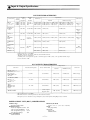
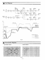
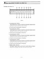
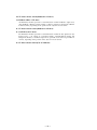
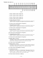
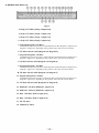
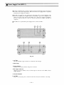
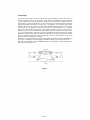
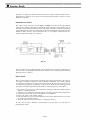
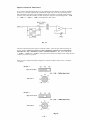
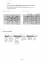
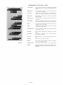
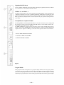
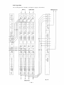
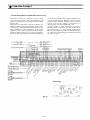
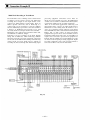
Operating Instruction Manual
TOA MIXING CONSOLE
Model RX-7-164, RX-7-248, RX-7-328
TOA ELECTRIC
CO., LTD.
KOBE, JAPAN
Contents
Precautions
..................................................
2
General Description . . . . . . . . . . . . . . . . . . . . . . . . . . . . . . . . . . . . . . . . . . . . 3
Features
. . . . . . . . . . . . . . . . . . . . . . . . . . . . . . . . . . . . . . . . . . . . . . . . . . ..... 4
Specifications & Characteristics . . . . . . . . . . . . . . . . . . . . . . . . . . . . . . . 6
Input & Output Specifications . . . . . . . . . . . . . . . . . . . . . . . . . . . . . . . .
7
Level Diagrams & Characteristics Diagrams . . . . . . . . . . . . . . . . . . . .
8
IPM-7 (Input Module) . . . . . . . . . . . . . . . . . . . . . . . . . . . . . . . . . . . . . . .
9
GFM-7 (Group/Foldback M o d u l e ) . . . . . . . . . . . . . . . . . . . . . . . . . . 11
GEM-7 (Group/Echo Module) . . . . . . . . . . . . . . . . . . . . . . . . . . . . . . . . 12
PGM-7 (Program Module) . . . . . . . . . . . . . . . . . . . . . . . . . . . . . . . . . . . 13
PHM-7 (Phones M o d u l e ) . . . . . . . . . . . . . . . . . . . . . . . . . . . . . . . . . . . . . . . 14
TBM-7 (Talkback Module) . . . . . . . . . . . . . . . . . . . . . . . . . . . . . . . . . . . 15
PSM-7 (Power Supply M o d u l e ) . . . . . . . . . . . . . . . . . . . . . . . . . . . . . . . . 16
Meter Panel (RXM-7-25, RXM-7-35, RXM-7-43) . . . . . . . . . . . . . . . . 17
RPS-7 (Power Supply Unit) . . . . . . . . . . . . . . . . . . . . . . . . . . . . . . . . . . 21
General Information on using the mixing console . . . . . . . . . . . . . . . 22
Function Details . . . . . . . . . . . . . . . . . . . . . . . . . . . . . . . . . . . . . . . . . . . . 24
Connection Examples I . . . . . . . . . . . . . . . . . . . . . . . . . . . . . . . . . . . . . . 31
Connection Examples II . . . . . . . . . . . . . . . . . . . . . . . . . . . . . . . . . . . . . 32
Module Replacement . . . . . . . . . . . . . . . . . . . . . . . . . . . . . . . . . . . . . . . . 33
Dimensional Diagrams (RX-7-164, RX-7-248, RX-7-328,
RXM-7-25, RXM-7-35, RXM-7-43, RPS-7). . . . . . . . . . . . . . . . . . . . 35
Block
D i a g r a m . . . . . . . . . . . . . . . . . . . . . . . . . . . . . . . . . . . . . . . . . . . . . . . 42
—1—
Precautions
1. Power Supply Unit (RPS-7)
The RPS-7 is separate from the console.
If the power switch on the RPS-7 is turned "on" without a connection between the
RPS-7 and the board using the accessory cable packed in the RPS-7, power is not
supplied to the board. The power switch must be "on" after the connection is made.
2. Power Supply
The RPS-7 is designed to operate on local AC (50/60Hz) mains, ±10%.
3. Fuse Replacement
The front panel of the RPS-7 is provided with a fuse holder for the AC line. Replace
only with the Identical Type and Value Fuse.
4. XLR (Cannon) Connector
The connectors are wired in such a manner that pin 1 is ground (shield), pin 2 is cold
(low, minus), and pin 3 is hot (high, plus).
5. Phantom Power Supply
Each RX-7 incorporates a 48V DC Phantom Power circuit. If phantom power is
required, the phantom power Master Switch on the rear panel of the Power Supply
Module should be "on", and the phantom power switch on the front panel of each
Input Module for which phantom power is required should be "on". When using
phantom power, avoid connecting unbalanced microphones or connecting other
equipment for which the output transformer center tap is grounded.
6. Description of components and functions
Various descriptions are used by different manufacturers, depending on each
manufacturer's standards. In our Operating and Instruction Manual, explanation of
components and functions is made according to our usage for terminology.
—2—
General Description
TOA's RX-7 is a modular 16, 24 or 32 input channel, 4 group output, 4 to 8 program
output mixing console. It is designed to meet a wide variety of requirements in
professional sound reinforcement and recording applications. It is well designed to
withstand the rigors of "on the road" use. Modular construction assures versatility in
functions, reliability and serviceability.
There are three "standard" models of RX-7 consoles. The RX-7-164 has 16 input
channels, 4 group outputs and 4 program outputs, and consists of the frame/case,
power supply unit, and modules, as follows.
16
2
2
2
1
1
1
1
1
IPM-7 (Input Module)
GFM-7 (Group/Foldback Module)
GEM-7 (Group/Echo Module)
PGM-7 (Program Module)
PHM-7 (Phones Module)
TBM-7 (Talkback Module)
PSM-7 (Power Supply Module)
RXM-7-25 (RX-7-164 Frame/Case)
RPS-7 (Power Supply Unit)
The RX-7-248 has 24 input channels, 4 group outputs and 8 program outputs, and
consists of the following modules, frame/case, and power supply unit.
24
2
2
4
1
1
1
1
1
IPM-7 (Input Module)
GFM-7 (Group/Foldback Module)
GEM-7 (Group/Echo Module)
PGM-7 (Program Module)
PHM-7 (Phones Module)
TBM-7 (Talkback Module)
PSM-7 (Power Supply Module)
RXM-7-35 (RX-7-248 Frame/Case)
RPS-7 (Power Supply Unit)
The RX-7-328 has 32 input channels, 4 group outputs and 8 program outputs, and
consists of the following modules, frame/case and power supply unit.
32
2
2
4
1
IPM-7 (Input Module)
GFM-7 (Group/Foldback Module)
GEM-7 (Group/Echo Module)
PGM-7 (Program Module)
PHM-7 (Phones Module)
1
1
1
1
TBM-7 (Talkback Module)
PSM-7 (Power Supply Module)
RXM-7-43 (RX-7-348 Frame/Case)
RPS-7 (Power Supply Unit)
All modules are usable for all RX-7 series consoles.
—3—
Features
INPUT MODULE
1. Phantom Power ON/OFF switch.
2. TRIM gain control offers extremely convenient operation when used in
conjunction with INPUT LEVEL switch.
3. MID-EQ is peaking equalization, and its center frequency can be set by a
continuously variable frequency control knob.
4. Two foldback control knobs for the 2 foldback busses. One is Pre-fader and the
other is associated with the PRE-POST selector switch for additional effects.
5. Two echo control knobs for the 2 echo busses. One is Post-fader and the other is
associated with the PRE-POST selector switch.
6. Channel ON/OFF pushbutton provides quick connection or disconnection of the
incoming signal to the mixing busses. The associated green LED illuminates when
the channel is connected to the mixing busses.
7. DIRECT OUT delivers a signal taken directly from the input module, bypassing
the pan pot and group assignment switches. This output is provided for direct
routing to a tape recorder track.
8. ACCESSORY SEND/RECEIVE jacks permit inserting a signal processing device
into the signal path, or can be used to re-route the signal in special applications.
9. PEAK indicator LED turns on when the input signal reaches l0dB above nominal,
to warn the operator to adjust the input sensitivity.
GROUP/FOLDBACK and GROUP/ECHO MODULES
1. AUX INPUT (Group/Foldback Module) and ECHO IN (Group/Echo Module) are
both balanced (transformer-isolated), with Low, Mid and High-EQ provided for
both types of inputs.
2. ACCESSORY SEND/RECEIVE jacks are located on the rear of the modules for
inserting signal processing devices.
3. Group On/Off pushbutton allows rapid punch-ins and punch-outs for temporary
killing of an output without disturbing the mixed level.
4. Foldback (FB) MASTER and ECHO SEND controls adjust each output's level
individually.
5. Peak indicators turn on the warn the operator when the signal level reaches l0dB
above nominal.
—4—
PROGRAM MODULE
1. Group 1, 2, 3 and 4 controls pick up the signal from the four group out busses and
assign them to the program output. The program output is therefore suitable for
feeding the signal to the house sound system.
2. Program On/Off pushbutton determines whether the individual program output
signal is to be fed to the rest of the sound system or other equipment.
3. Peak indicator for detecting overload condition.
4. Program channel mixed signal can be monitored through headphones by phones
selector switches (L and/or R) prior to feeding the signal to the rest of the sound
system or other equipment.
PHONES MODULE
1. Foldback 1 or 2, Echo 1 or 2, Program L and R, Air Monitor L and R can be
monitored through headphones by a cluster of selection switches.
2. Air Monitor L and R inputs are provided with PHANTOM power ON/OFF switch.
3. L and R monitor output jacks are located on the rear for monitor loudspeakers
(power amplifiers).
TALKBACK MODULE
1. Oscillator/Pink noise Generator includes 400Hz, 1kHz and 10kHz sine wave
signals and pink noise for signal tracing, tape machine alignment, sound system
setup or trouble shooting purposes.
2. These signals can be fed to all mixing busses except the cue buss.
—5—
Specifications & Characteristics
GENERAL SPECIFICATIONS RX-7-164, RX-7-248 AND RX-7-328
Frequency Response (Measurement of source impedance 150
ohms)
+0dB, -0.5dB; 50Hz to 20kHz +0dB, -2.0dB; 20Hz to 30 kHz
Total Harmonic Distortion
Less than 0.5% at +4dB* output at 1kHz
Hum and Noise (20Hz to 20kHz, input termination of 150 ohms,
Input Level Switches at -60dB, Input Trim at 0)
-128dB* Equivalent Input Noise
-130dB* Equivalent Input Noise, IHF A weighted
-64dB* (68dB S/N) Group Out, Group and one Input Fader
at nominal level
-64dB* (68dB S/N) Program Out, PGM Master and Group
controls at max. level, all Group Faders and one Input Fader
at nominal level
-64dB* (68dB S/N) FB Out or Echo Send, FB Master or Echo
Send control and one FB or Echo mix control at nominal
level
Maximum Voltage Gain
84dB CH IN to Group Out
84dB CH IN to Program Out
84dB CH IN to FB Out
94dB CH IN to Echo send
20dB AUX IN to Group Out
20dB ECHO IN to Group Out
10dB SUB IN to Group Out
Equalization (CH IN, AUX IN, ECHO IN)
LOW 100Hz
Shelving (±15dB maximum)
MID 200Hz to 5kHz, variable Peaking (±15dB maximum)
HIGH 10kHz
Shelving (±15dB maximum)
High Pass Filter
12dB/octave roll off switchable for 3dB down at 60Hz or
120Hz
Oscillator/Generator
Switchable sine wave at 400Hz, 1kHz and 10kHz (1.0%
Total Harmonic Distortion at +4dB* output) or pink noise.
Inputs and Outputs
See accompanying tables of Input Characteristics and
Output Characteristics.
Crosstalk
-60dB at 1kHz, input to output
VU Meters (0VU = +4dB* output)
RX-7-164
4 large, illuminated meters; switchable for Group or
Program
3 smaller, illuminated meters; switchable for 2 Foldback or 2
Echo and CUE or TB
RX-7-248
4 large, illuminated meters for Group
4 large, illuminated meters, switchable for Program 1—5,
2—6, 3—7, and 4—8
3 smaller, illuminated meters; switchable for 2 Foldback or 2
Echo and CUE or TB
RX-7-328
4 large, illuminated meters for Group
4 large, illuminated meters, switchable for Program 1—5,
2—6, 3—7, and 4—8
6 smaller, illuminated meters for 2 Foldback, 2 Echo, CUE
and TB
Peak Indicators
LED built into each input turns on when the pre-Fader level
reaches 10dB above nominal.
LED built into each Group, FB, Echo and Program Out turns
on when the output level reaches 10dB above nominal.
Phantom Power
48V DC is applied to balanced input transformers for
powering condenser microphones.
Finish
Black panel, rosewood trim, padded armrest
Dimensions (W×D×H)
RX-7-164
40-3/8" × 32-3/8" × 13-7/8" (1026 × 822 × 353 mm)
RX-7-248
55-5/8" × 33-1/4" × 15" (1412 × 843 × 382 mm)
RX-7-328
66-5/8" × 32-3/4" × 15" (1691 × 833 × 382 mm)
Weight
RX-7-164; 78kg (171 pounds)
RX-7-248; 109kg (240 pounds)
RX-7-328; 138kg (303 pounds)
Power Consumption
RX-7-164; 120VA maximum
RX-7-248; 145VA maximum
RX-7-328; 170VA maximum
Accessory
Talkback Microphone
*0dB is referenced to 0.775V RMS
—6—
Input & Output Specifications
RX-7 INPUT CHARACTERISTICS
Connection
Level
Switch
Actual
Load
Impedance
Input Level*
For Use
With
Nominal
Sensitivity*
Connector**
Nominal
MAX. Before Clip
1.2k ohms
1.7k ohms
1.7k ohms
-80dB (0.08mV) -60dB (0.78mV) to -30dB (25mV) -26dB (39mV) to +4dB (1.23V)
ohms mics or -60dB (0.78mV) -40dB (7.8mV) to -10dB (250mV) -6dB (390mV) to +24dB (12.3V)
-40dB (7.8mV) -20dB (78mV) to +10dB (2.5V)
lines
+14dB (3.9V) to +24dB (12.3V)
AUX IN 1 & 2
ECHO IN
1&2
2.5k ohms
600 ohm lines -16dB (123mV)
+4dB (1.23V)
+24dB(12.3V)
SUB IN 1-4
2.5k ohms
600 ohm lines -6dB (390mV)
+4dB (1.23V)
+24dB (12.3V)
INPUT
1—16, 1—24,
or 1—32
-60dBm
-40dBm
-20dBm
AIR
MONITOR
L&R
50 to 600
50 to 600
ohms mics
4.5k ohms
TALK BACK
IN
ACCESSORY
(RCV)
INPUT 1—16,
1—24 or 1—32
10k ohms
lines
20k ohms
GROUP 1—4
XLR-3-31
type
XLR-3-31
type
-70dB (0.25mV) -70dB (0.25mV) to -40dB (7.8mV)
-36dB (12.3mV) to -6dB (390mV)
-80dB (0.08mV) -60 dB (0.78mV)
-26dB (39mV)
-16dB (123mV) +4dB (1.23V)
+24dB (12.3V)
-6dB (390mV)
+24dB (12.3V)
+4dB (1.23V)
XLR-3-31
type
XLR-3-31
type
TRS
Phone Jack
*0dB is referenced to 0.775V RMS.
**All XLR connectors are floating (balanced) and transformer-isolated.
TRS phone jacks are unbalanced.
Sensitivity is the level required to produce a nominal output of +4dB (1.23V), or the specified nominal output
level if other than +4dB.
RX-7 OUTPUT CHARACTERISTICS
Output Level*
Connection
Actual Source Impedance
Connector**
For Use With Nominal
Nominal
MAX Before Clip
GROUP OUT 1—4
PROGRAM OUT 1—4 or 1—8
F.B. OUT 1 & 2
ECHO SEND 1 & 2
T.B. OUT
80 ohms
600 ohm Lines
+4dB (1.23V)
+24dB (12.3V)
XLR-3-32 type
ACCESSORY (SEND)
INPUT 1—16
1—24 or 1—32
GROUP 1—4
110 ohms
10k ohm Lines
+4dB (1.23V)
+24dB (12.3V)
TRS Phone Jack
CH IN
(DIRECT OUT)
PHONES OUT
(L&R)
110 ohms
10k ohm Lines
+4dB (1.23V)
+24dB (12.3V)
TRS Phone Jack
8 ohms or higher
impedance lines
-10dB (250mV)
+10dB(2.5V)
TRS Phone Jack
(HEAD) PHONES
*0dB is referenced to 0.775V RMS.
**All XLR connectors are floating (balanced) and transformer-isolated.
TRS phone jacks are unbalanced except headphone jacks, wired Tip=Left, Ring=Right, Sleeve=Common
POWER SUPPLY UNIT (RPS-7) SPECIFICATIONS
AC Line Voltage
AC mains 50Hz or 60Hz
DC Output Voltages
±21.5V (for amplifier circuit)
+12V (for relay and LED's)
+48V (for phantom power)
+6V (VU meter lamps)
Power Consumption
170VA maximum
Dimensions (W×D×H)
21-1/8" × 14" × 7" (538 × 355 × 179 mm)
1.8A
2.7A
0.17A
1.6A
Weight
18kg (40 pounds)
Accessories
Power cord
Umbilical cable
—7—
Level Diagrams
(Fig. 1)
Characteristics Diagrams
EQUALIZER CURVES
FILTER CURVES
(Fig. 2)
—8—
Input Module (IPM-7)
1. XLR type INPUT connector is balanced, transformer-isolated and accepts low impedance
sources from -60dB to +10dB. Proper adjustment of both the INPUT LEVEL Switch and
TRIM Knob make it possible to provide the optimum setting for each input.
2. GROUND (GND) LIFT Switch is for Pin 1, which makes it easy to avoid ground loops
that are often caused in connection with other equipment and that may induce hum noise.
Sliding the ground lift switch from the NORMAL position to the LIFT position cuts
ground loops and may reduce hum noise. For most applications it should be set to the
NORMAL position.
3. ACCESSORY SEND/RECEIVE (ACCESSORY) jacks are unbalanced with an impedance
of 10k ohms and a nominal level of +4dB. These jacks allow inserting signal processing
devices into the signal path. The regular signal path is interrupted at the RCV jack by
inserting a plug into it.
4. DIRECT OUT jack is unbalanced with an impedance of 10k ohms and a nominal level of
+4dB. The jack delivers the signal prior to the pan pot and bus assign switches.
5. PHANTOM power switch permits the user to supply 48V DC through the input connector
to a condensor microphone. If phantom power is required, the phantom power master
switch on the rear panel of the Power Supply Module must be ON before the phantom
power switch on each Input Module is turned ON.
6. PHASE switch reverses the polarity of the incoming audio signal. At "N" (normal)
position, Pin No. 3 of the XLR connector is hot and Pin No. 2 is low. At the "R" (reverse)
position, Pin No. 2 is hot. Slide the phase switch to the appropriate position to match the
polarity of the source. Polarity can often be intentionally reversed to eliminate leakage
from adjacent microphones or to create special acoustic effects.
7. INPUT LEVEL switch has 3 settings, -60dB, -40dB and -20dB at the "0" position of the
TRIM knob. Adjust the input level switch, depending on the output level of microphones
or associated equipment.
8. TRIM knob varies the gain of a head-amplifier and provides a continuously variable
control of gain in the range of 0 to —30dB from the input level switch position. It permits
optimum setting of the input channel gain and provides good S/N ratio when used in
conjunction with the INPUT LEVEL switch. Another use of the trim knob is to allow
every input fader to be in a horizontally straight line with proper adjustment of the trim
knob.
9. EQUALIZER consists of three frequency ranges. The HIGH and LOW shelving type
equalizers provide 15dB of boost and attenuation at 10kHz and l00Hz, respectively. The
MID equalizer employs peaking type equalization which provides 15dB boost and
attenuation. The MID-EQ center frequency can be easily set at any frequency between
200Hz and 5kHz by use of a continuously variable frequency setting knob. The "0"
position of each equalizer provides flat response.
10. EQUALIZER IN/OUT switch puts the input signal either in circuit or out of circuit of the
equalizer. The OUT position provides flat response no matter what the position of the EQ
controls.
11. HIGH PASS filter switch provides flat response when OFF, but can be set to cut the
frequency response either below 60Hz or below 120Hz at a 12dB/octave rate.
12. FOLDBACK knobs provide for two independent foldback mixes. The No. 1 foldback knob
mixes the signal pre-fader, but the No. 2 foldback knob is associated with the Pre-Post
fader selector switch which permits its mix to be either Pre or Post fader.
(Fig. 3)
—9—
13. Echo knobs provide for two independent echo mixes. The No. 1 echo knob mixes the
signal post-fader, but the No. 2 echo knob is associated with the Pre-Post fader selector
switch.
14. PAN POT adjusts the relative output level (balance) to the four mixing busses. It is
operated in conjunction with the group assign pushbuttons to put the desired level of
output signal adjusted by the pan pot onto the mixing busses selected by the group assign
pushbuttons. Any selection of the four group assign pushbuttons applies some level of the
output to the related mixing bus, according to wherever the pan pot is situated. Panning to
the center position provides equal output to any of the four mixing busses selected by the
group assign pushbuttons. The following illustration indicates details on the
combinations available of the group asign switches and the pan pot.
(Fig. 4)
15. GROUP ASSIGN (GROUP) pushbuttons apply the output to any combination of the four
mixing busses.
16. CHANNEL ON/OFF (CHANNEL) pushbutton connects or disconnects the input signal to
the mixing busses. The green LED illuminates when the channel is "on".
17. PEAK level indicator turns on when the post-EQ and pre-fader signal level reaches 10dB
above nominal.
18. FADER travel continuously varies the channel level to the four mixing busses. It affects
the channel's Foldback 2 and Echo 2 bus sends when the respective Pre-Post selector
switches are set at the "post" position and also affects the echo 1 bus sends. The nominal
level is "0" position. The fader travel is calibrated in dB and assures very smooth
operation.
19. CUE pushbutton assigns the post-EQ, pre-fader signal to the cue bus for monitoring with
headphones, monitor speakers, and/or the cue VU meter. A separate cue VU meter is
provided on the RX-7-328, but the cue and talkback VU meter is combined and is
switchable on the RX-7-164 and RX-7-248.
— 10 —
Group/Foldback Module (GFM-7)
1. AUX INPUT connector (XLR type) is balanced, transformer-isolated. The nominal level
and impedance are +4dB and 600 ohms respectively.
2. GROUND (GND) LIFT switch is for pin 1, which is used to avoid ground loops that are
often caused in connection with other equipment and that may induce hum. Sliding the
ground lift switch from the NORMAL position to the LIFT position cuts ground loops and
may reduce hum. For most applications it should be set to the NORMAL position.
3. ACCESSORY SEND/RECEIVE jacks are unbalanced and their nominal level and
impedance are +4dB and 10k ohms, respectively. They provide the ability to insert signal
processing devices into the signal path for special applications. The regular signal path
between the group mixing bus and group out is interrupted at the RCV jack by inserting a
plug into it.
4. SUB INPUT connector (female XLR type) is balanced, transformer-isolated. Its nominal
level and impedance are +4dB and 600 ohms, respectively. This connector is useful for
cascade connection with another mixer to expand the input capacity.
5. GROUND (GND) LIFT switch is for pin 1 of the Sub Input connector.
6. FOLDBACK PEAK level indicator LED turns on when the foldback output signal level
reaches l0dB above nominal.
7. FOLDBACK MASTER control adjusts the output signal level of FB OUT on the rear of the
frame.
8. EQUALIZER for AUX INPUT consists of the following three equalizers
HIGH
10kHz
±15dB boost/cut
shelving type
MID
200—5kHz variable
±15dB boost/cut
peaking type
LOW
l00Hz
±15dB boost/cut
shelving type
Flat frequency response is provided at "0" position of each equalizer.
9. EQUALIZER IN/OUT switch permits the equalizer to be either in circuit or out of circuit.
10. GROUP ASSIGN pushbuttons apply the AUX input to any of the four group mixing
busses.
11. AUX INPUT master control adjusts the level of the signal to be fed to the group mixing
busses.
12. CUE pushbutton assigns the signal (pre AUX INPUT master control) to the cue bus for
monitoring with headphones, monitor speakers, and/or the cue VU meter. A separate cue
VU meter is provided on the RX-7-328, but the cue and talkback VU meter is combined
and is switchable on the RX-7-164 and RX-7-248.
13. GROUP ON/OFF pushbutton connects or disconnects the signal to the GROUP out and
group out bus. The adjacent green LED illuminates when the group out is "on".
14. PEAK level indicator turns on when the group output signal level reaches l0dB above
nominal.
15. GROUP FADER TRAVEL is calibrated in dB and insures very smooth operation. The
fader controls the level of the signal to be fed to the group out and group out bus.
16. CUE pushbutton assigns the pre group-fader signal to the cue bus for monitoring with
headphones, monitor speakers, and/or the cue VU meter. A separate cue VU meter is
provided on the RX-7-328, but the cue and talkback VU meter is combined and is
switchable on the RX-7-164 and RX-7-248.
(Fig. 5)
— 11 —
Group/Echo Module (GEM-7)
1. ECHO IN connector (XLR type) is balanced, transformer-isolated. The nominal level and
impedance are +4dB and 600 ohms, respectively.
2. GROUND (GND) LIFT Switch is for pin 1, which is used to avoid ground loops that are
often caused in connection with other equipment and that may induce hum. Sliding the
ground lift switch from the NORMAL position to the LIFT position cuts ground loops and
may reduce hum. For most applications it should be set to the NORMAL position.
3. ACCESSORY SEND/RECEIVE jacks are unbalanced and their nominal level and
impedance are +4dB and 10k ohms, respectively. They provide the capability to insert
signal processing devices into the signal path for special applications. The regular signal
path between the group mixing bus and group out is interrupted at the RCV jack by
inserting a plug into it.
4. SUB INPUT connector (female, XLR type) is balanced, transformer-isolated. Its nominal
level and impedance are +4dB and 600 ohms, respectively. This connector is useful for
cascade connection with another mixer to expand the input capacity.
5. GROUND (GND) LIFT switch is for pin 1 of the Sub Input connector.
6. ECHO SEND PEAK level indicator turns on when the echo send output signal level
reaches l0dB above nominal.
7. ECHO SEND master control adjusts the output signal level of ECHO SEND output on the
rear of the frame.
8. EQUALIZER for ECHO IN consists
HIGH
10kHz
MID
200—5kHz variable
LOW
l00Hz
Flat frequency response is provided
of the following three equalizers
±15dB boost/cut
shelving type
±15dB boost/cut
peaking type
±15dB boost/cut
shelving type
at "0" position of each equalizer.
9. EQUALIZER IN/OUT switch permits the equalizer to be either in circuit or out of circuit.
10. GROUP ASSIGN pushbuttons apply the ECHO input to any of the four mixing busses.
11. ECHO IN master control adjusts the level of the signal to be fed to the group mixing
busses.
12. CUE pushbutton assigns the signal (pre ECHO IN master control) to the cue bus for
monitoring with headphones, monitor speakers, and/or the cue VU meter. A separate cue
VU meter is provided on the RX-7-328, but the cue and talkback VU meter is combined
and is switchable on the RX-7-164 and RX-7-248.
13. GROUP ON/OFF pushbutton connects or disconnects the signal to the GROUP out and
group out bus. The adjacent green LED illuminates when the group out is "on".
14. PEAK level indicator turns on when the group output signal level reaches l0dB above
nominal.
15. GROUP FADER TRAVEL is calibrated in dB and insures very smooth operation. The
fader controls the level of the signal to be fed to the group out and group out bus.
16. CUE pushbutton assigns the pre group-fader signal to the cue bus for monitoring with
headphones, monitor speakers, and/or the cue VU meter. A separate cue VU meter is
provided on the RX-7-328, but the cue and talkback VU meter is combined and is
switchable on the RX-7-164 and RX-7-248.
(Fig. 6)
— 12 —
Program Module (PGM-7)
Each program module incorporates two program output channels (programs A and B) and
each program channel can be controlled independently.
1. PROGRAM OUTPUT B connector (XLR type) is balanced, transformer-isolated. The
nominal level and impedance are +4dB and 600 ohms, respectively. The program output B
signal is derived from one of the four group out busses.
2. GROUND (GND) LIFT switch is for pin 1, which is used to avoid ground loops that are
often caused in connection with other equipment and that may induce hum. Sliding the
ground lift switch from the NORMAL position to the LIFT position cuts ground loops and
may reduce hum. For most applications it should be set to the NORMAL position.
3. PROGRAM OUTPUT A connector (XLR type) is balanced, transformer-isolated. The
nominal level and impedance are +4dB and 600 ohms, respectively. The program output
A signal is derived from one of the four group out busses.
4. GROUND (GND) LIFT switch is for pin 1, which is used to avoid ground loops that are
often caused in connection with other equipment and that may induce hum. Sliding the
ground lift switch from the NORMAL position to the LIFT position cuts ground loops and
may reduce hum. For most applications it should be set to the NORMAL position.
PROGRAM OUT "A" SECTION
5. GROUP 1, 2, 3 and 4 controls pick up the signal from the four Group out busses, and
assign them to this program output channel.
6. PROGRAM MASTER control adjusts the overall mixed signal level of any four Group
signals assigned to this channel.
7. PROGRAM ON/OFF pushbutton connects or disconnects the program signal to the
program output connector. The green LED illuminates when the program out is "on".
8. PEAK level indicator turns on when the program output signal level reaches l0dB above
nominal.
9. PHONES selector switches assign the program signal of this channel to the phones
module. The switches allow for the selection of L (left) and/or R (right) of the phones
output. If the program output is required for monitoring via headphones, the program
monitoring button on the phones module must be ON.
PROGRAM OUT "B" SECTION
Functions on program out B section are the same as the Program out A.
10. GROUP 1, 2, 3 and 4 controls
11. PROGRAM MASTER control
12. PROGRAM ON/OFF pushbutton
13. PEAK level indicator
14. PHONES selector switches
(Fig. 7)
— 13 —
Phones Module (PHM-7)
1. AIR MONITOR (Ceiling Microphone) inputs, XLR type connectors (L and R) are balanced,
transformer-isolated. The nominal levels and impedances are —70dB and 600 ohms,
respectively.
2. PHONES OUT jacks (L and R) are unbalanced. The nominal levels and impedances are
+4dB and 10k ohms, respectively. The jacks provide the signals selected by the phones
selector switches for monitoring on the front and can be connected to an amplifier and
monitor speakers for use as a monitor system.
3. PHANTOM POWER switch applies 48V DC across the balanced leads and shielded cable
of air monitor microphone (ceiling Microphone).
4. AIR MONITOR (CEILING MICROPHONE) TRIM knobs (L and R) provide continuously
variable control within a range of 0dB to —l0dB of the air monitor input sensitivity level.
5. PHONES selector buttons permit the operator to select the desired signals for monitoring.
The switches provide a monaural signal of FOLDBACK 1 and 2, ECHO 1 and 2, and a stereo
signal of PROGRAM (L and R). When the switches are engaged, a bright color indication
appears in the buttons. Insure that the phones selector button is "on" when the program
output is monitored via headphones.
6. PHONES LEVEL control adjusts the signal level of the phones out L and R, and adjusts the
two phones outputs simultaneously.
7. CUE indicator turns on when any cue button is depressed, warning the operator that he is
monitoring the signal from the cue bus.
8. PHONES output jacks are stereo type (for stereo headphones). When two phones are used,
phones must be selected so that the total impedance will be more than 8 ohms.
(Fig. 8)
— 14 —
Talkback Module (TBM-7)
1. TALKBACK OUT connector (XLR type) is balanced, transformer-isolated, and its nominal
level and impedance are +4dB and 600 ohms, respectively. The talkback output includes
the oscillator/pink noise generator signal or talkback mic input, depending on the switch
status on the module. The oscillator/pink noise generator function is used for matching
input and output levels with other associated equipment, and the talkback function is for
communication between a recording booth and the outside.
2. GROUND (GND) LIFT Switch is for pin 1, which is used to avoid ground loops that are
often caused in connection with other equipment and that may induce hum. Sliding the
ground lift switch from the NORMAL position to the LIFT position cuts ground loops and
may reduce hum. For most applications it should be set to the NORMAL position.
3. This cluster of buttons derives signals from the desired mixing busses, Group busses 1,2,3,
and 4, Foldback 1 and 2, and Echo 1 and 2, and assigns them to the talkback output.
4. This cluster of buttons selects the required testing signal from the available Pink noise and
Sinusoidal waves, 10kHz, 1kHz and 400Hz. When the oscillator is not used, the switch
must be "off".
5. OSC LEVEL control is provided for adjusting the oscillator output to the desired level.
6. OSC indicator turns on when any of the signal selector buttons is depressed.
7. TALKBACK INPUT CONNECTOR (XLR type) is balanced, transformer-isolated, and its
nominal level and impedance are —60dB and 600 ohms, respectively. An accessory
microphone is connected.
8. TALKBACK LEVEL control adjusts the microphone input level of the signal to be fed to the
mixing busses.
9. PRESS TO TALK pushbutton connects the talkback microphone signal to the mixing
busses when pressed. When the button is released, any oscillator signals which may have
been selected are fed.
(Fig. 9)
— 15 —
Power Supply Module (PSM-7)
1. DC POWER INPUT connector accepts DC power from the power supply unit (RPS-7). The
PSM-7 is connected to the RPS-7 with an accessory umbilical cable. The power switch on
the RPS-7 will not turn on without this connection between the RPS-7 and PSM-7.
2. Ground (GND) terminal for the chassis of the RX-7.
3. PHANTOM POWER MASTER switch applies 48V DC which is then supplied to Input
modules and Phones module.
(Fig. 10)
— 16 —
Meter Panel (RXM-7-25, RXM-7-35, RXM-7-43)
METER PANEL (RXM-7-25)
(Fig. 11)
1. Group I/Program 1 VU Meter
An illuminated VU meter provides a visual indication of either Group 1 output level (Post
Group 1 Master Fader) or Program 1 output level (Post Program 1 Master Control),
depending on the position of the adjacent selection switch.
2. VU meter selector switch (Group 1 or Program 1)
3. Group 2/Program 2 VU Meter
An illuminated VU meter provides a visual indication of either Group 2 output level (Post
Group 2 Master Fader) or Program 2 output level (Post Program 2 Master Control),
depending on the position of the adjacent selection switch.
4. VU meter selector switch (Group 2 or Program 2)
5. Group 3/Program 3 VU Meter
An illuminated VU meter provides a visual indication of either Group 3 output level (Post
Group 3 Master Fader) or Program 3 output level (Post Program 3 Master Control),
depending on the position of the adjacent selection switch.
6. VU meter selector switch (Group 3 or Program 3)
7. Group 4/Program 4 VU Meter
An illuminated VU meter provides a visual indication of either Group 4 output level (Post
Group 4 Master Fader) or Program 4 output level (Post Program 4 Master Control),
depending on the position of the adjacent selection switch.
8. VU meter selector switch (Group 4 or Program 4)
9. Foldback 1/Echo 1 VU meter
An illuminated VU meter provides a visual indication of either Foldback 1 output level,
(Post Foldback 1 Master Volume Control) or Echo 1 output level (Post Echo 1 Master
Volume Control), depending on the position of the adjacent selector switch.
— 17 —
10. VU meter selector switch (Foldback 1 or Echo 1)
11. Foldback 2/Echo 2 VU meter
An illuminated VU meter provides a visual indication of either Foldback 2 output level,
(Post Foldback 2 Master Volume Control) or Echo 2 output level (Post Echo 2 Master
Volume Control), depending on the position of the adjacent selector switch.
12. VU meter selector switch (Foldback 2 or Echo 2)
13. Cue/Talk back VU meter
An illuminated VU meter provides a visual indication of either the Cue signal level (the
signal fed by a cue switch on each Input module, Group/Foldback module and
Group/Echo module) or Talkback output level (post OSC level control or post TB level
control), depending on the position of the adjacent selector switch.
14. VU meter selector switch (Cue or Talkback)
— 18 —
METER PANEL (RXM-7-35)
(Fig. 12)
1. Group 1 VU Meter (Group 1 output level)
2. Group 2 VU Meter (Group 2 output level)
3. Group 3 VU Meter (Group 3 output level)
4. Group 4 VU Meter (Group 4 output level)
5. Program 1/Program 5 VU Meter
An illuminated VU meter provides a visual indication of either Program 1 output level or
Program 5 output level, depending on the position of the adjacent selector switch.
6. VU meter selector switch (Program 1 or Program 5)
7. Program 2/Program 6 VU Meter
An illuminated VU meter provides a visual indication of either Program 2 output level or
Program 6 output level, depending on the position of the adjacent selector switch.
8. VU meter selector switch (Program 2 or Program 6)
9. Program 3/Program 7 VU Meter
An illuminated VU meter provides a visual indication of either Program 3 output level or
Program 7 output level, depending on the position of the adjacent selector switch.
10. VU meter selector switch (Program 3 or Program 7)
11. Program 4/Program 8 VU Meter
An illuminated VU meter provides a visual indication of either Program 4 output level or
Program 8 output level, depending on the position of the adjacent selector switch.
12. VU meter selector switch (Program 4 or Program 8)
13. Foldback 1/Echo 1 VU meter
An illuminated VU meter provides a visual indication of either Foldback 1 output level
(Post Foldback 1 Master Volume Control) or Echo 1 output level (Post Echo 1 Master
Volume Control), depending on the position of the adjacent selector switch.
14. VU meter selector switch (Foldback 1 or Echo 1)
15. Foldback 2/Echo 2 VU meter
An illuminated VU meter provides a visual indication of either Foldback 2 output level
(Post Foldback 2 Master Volume Control) or Echo 2 output level (Post Echo 2 Master
Volume Control), depending on the position of the adjacent selector switch.
16. VU meter selector switch (Foldback 2 or Echo 2)
17. Cue/Talk back VU meter
An illuminated VU meter provides a visual indication of either the Cue signal level (the
signal fed by a cue switch on each Input module, Group/Foldback module and
Group/Echo module) or Talkback output level (post OSC level control or post TB level
control), depending on the position of the adjacent selector switch.
18. VU meter selector switch (Cue or Talkback)
— 19 —
METER PANEL (RXM-7-43)
(Fig. 13)
1. Group 1 VU Meter (Group 1 output level)
2. Group 2 VU Meter (Group 2 output level)
3. Group 3 VU Meter (Group 3 output level)
4. Group 4 VU Meter (Group 4 output level)
5. Program 1/Program 5 VU Meter
An illuminated VU meter provides a visual indication of either Program 1 output level or
Program 5 output level, depending on the position of the adjacent selector switch.
6. VU meter selector switch (Program 1 or Program 5)
7. Program 2/Program 6 VU Meter
An illuminated VU meter provides a visual indication of either Program 2 output level or
Program 6 output level, depending on the position of the adjacent selector switch.
8. VU meter selector switch (Program 2 or Program 6)
9. Program 3/Program 7 VU Meter
An illuminated VU meter provides a visual indication of either Program 3 output level or
Program 7 output level, depending on the position of the adjacent selector switch.
10. VU meter selector switch (Program 3 or Program 7)
11. Program 4/Program 8 VU Meter
An illuminated VU meter provides a visual indication of either Program 4 output level or
Program 8 output level, depending on the position of the adjacent selector switch.
12. VU meter selector switch (Program 4 or Program 8)
13. Foldback 1 VU meter (Foldback 1 output level)
14. Foldback 2 VU meter (Foldback 2 output level)
15. Echo 1 VU Meter (Echo 1 output level)
16. Echo 2 VU Meter (Echo 2 output level)
17. Cue VU meter
18. Talkback VU Meter
— 20 —
Power Supply Unit (RPS-7)
In order to minimize hum, and also to break up the total weight and to protect the body of
the RX-7 from rough transportation, RX-7 series mixers are equipped with a separately
packaged power supply unit (RPS-7).
The RX-7 is designed so that without the connection of the accessory umbilical cable
between the PSM-7 power supply module and the RPS-7, power is not supplied to the
mixer even if the power switch on the RPS-7 is on. The power switch on the RPS-7,
therefore, must be turned on after the connection between the PSM-7 and RPS-7 is
completed.
The RPS-7 is a regulated DC power supply unit to activate the RX-7.
(Fig. 14)
1. AC Fuse
The fuse should be replaced with one of identical value and type.
2. Pilot Lamp
3. Power Switch
Pushbutton alternately switches AC power on and off.
4. DC output connector
With the accessory umbilical cable, the DC output is connected to the PSM-7 (Power
Supply Module).
5. Ground Terminal
6. AC Inlet
Plug an accessory AC power cord into the AC inlet and secure it with the cord clamp.
— 21 —
General Information on using the mixing console
* Impedance
Generally speaking, there are two rules to follow when connecting equipment outputs to the
inputs of other equipment.
1. Try to properly match the impedances of the outputs and inputs.
2. Connect low impedance outputs to high impedance input.
The above rules about impedance are very important and should be taken into consideration
in all connections between equipment.
* Difference between Professional and HI-FI type equipment
Microphones, tape recorders, wireless tuners, and various other equipment may be connected
to the inputs of the mixing console. The associated equipment to be connected to the mixer
outputs includes graphic equalizers, limiters, compressors and power amplifiers. The RX-7 is
equipped with an accessory send (output) and receive (input) on each input module (IPM-7)
and group module (GFM/GEM-7). Various equipment such as echo and reverb equipment,
graphic equalizers, and noise gates, are available as associated equipment to be connected to
the accessory send and receive. All the above associated equipment are generally grouped for
professional use and HI-FI use (for consumer use) regardless of their functions. Generally, the
output of professional equipment is balanced (transformer-isolated) with an impedance of 600
ohms and is designed to drive 600-ohm or higher impedance loads. The nominal output level of
most professional equipment is +4dB (1.23V RMS). As for the input/output terminals, XLR
type audio connector or TRS type connectors are employed for professional equipment.
The output of HI-FI equipment is generally unbalanced with an impedance of several kiloohms and designed to drive lOK-ohm or higher impedance loads. The nominal output level of
most HI-FI equipment is —20dB to —l0dB. RCA pin connectors are employed for the
input/output terminals of HI-FI equipment.
* Balanced type and unbalanced type
If there is any problem as to the grounding method or if cable has to be extended (over 10 feet),
experience proves that hum or noise is picked up easily unless the balanced type is used. In the
RX-7, balanced (transformer-isolated) circuits are employed for input/output terminals
necessary for long cable connections, but unbalanced circuits are employed for input/output
terminals to be connected to adjacent associated equipment.
Recently, electronically balanced circuits have been used in some professional equipment
instead of transformer-isolated balanced circuits. It must be noted that special care should be
taken as to the grounding method and ground line connection when using equipment with
electronically balanced circuits. In particular, problems may occur if an electronically
balanced output is connected to the unbalanced input of other equipment. This will not occur
with transformers because the transformer-isolated, balanced circuit is not only balanced, but
isolates other equipment, thus reducing the possible problems. The electronically balanced
circuit, on the other hand, has advantages of better frequency response and quicker slew rate.
However, when applying it for on-the-road use where each set-up differs, trouble may occur
more often as compared with the transformer-isolated circuit.
— 22 —
* Ground loops
AC ground is provided to the RX-7 and all associated equipment, and this may cause an
increase in hum noise if care is not taken in connecting other equipment to the mixer. This is
because a ground loop is made through the shields of the connection cable and the AC line as
shown in Fig. 15, increasing hum noise. To solve this problem, either the chassis ground of the
signal line should be disconnected at either piece of equipment, or the chassis earth ground
should be disconnected, so that the ground loop is eliminated. This problem can not be easily
solved in the case of equipment connected to unbalanced signal lines. However, it is highly
dangerous to disconnect the AC ground, as microphone and other equipment connected to the
mixing console are often touched directly by the hand. This may cause an electric shock in the
case of electricity leakage, if any other connected equipment is touched. Therefore the chassis
ground line should be disconnected. Whether to disconnect the chassis ground line of either
piece of equipment depends on various conditions, therefore, they should be checked and
determined for each installation condition.
In the RX-7, a ground lift switch is provided on the balanced inputs and outputs with XLR type
connectors (excluding air monitor inputs and talkback input) to prevent ground loops.
This switch is ordinarily set to the NORMAL position, and should be set to the LIFT position
only when ground loops occur.
(Fig. 15)
— 23 —
Function Details
The RX-7 is a sophisticated mixer with many functions. Details on important functions are
shown below in order for you to get the best operation and performance and also to avoid
mistakes in operation.
* Phantom Power Switch
The switch on the front panel of both IPM-7 and PHM-7 provides for 48V DC phantom
powering for condenser microphones through the input connectors on the modules. Fig. 16
elaborates on the phantom powering circuit, and shows that balanced outputs of associated
equipment should be connected to the inputs. Connection with unbalanced outputs does not
damage the RX-7, but may cause troubles like noise, etc. Accordingly, turn the switch "off"
whenever unbalanced inputs are connected.
(Fig. 16)
The Lift position on the ground lift switch cuts the phantom power even if the phantom power
switch is "ON". The ground lift switch therefore must be set at "Normal" position whenever
phantom power is required.
* Phase Switch
The use of more than one microphone for picking up the same program source may cause an
out-of-phase condition resulting in acoustic phasing cancellations. The acoustic phasing
cancellation is particularly noticeable in the low frequencies and the low frequencies may not
be sufficiently reproduced. Accordingly, all inputs on the mixer must be in principle in the
same phase. The following method is advisable for checking inputs for correct phase.
1. Place mics 1 and 2 close to the same sound source with appreciable bass, setting the phase
switches at Normal positions.
2. Adjust the level of both mics, using the input level switches and trim controls on the mixer.
3. Listen to the blend of the two mics through the cue headphones.
4. Reverse the phase of mic 2 Phase switch.
5. If the bass increases, leave the switch in the Reverse position. If the bass decreases, return
the switch to the Normal position.
6. Check all other mics in the same manner, comparing with mic 1.
In some cases it may be desirable to intentionally reverse the phase of certain mics for
improving the sound.
— 24 —
*Input Level Switch & Trim Control
In accordance with the input signal level, the combination of the Input Level Switch and Trim
Control on each input module helps establish the input fader at an easy-operation position.
When the Peak level indicator (the red LED) remains on or flashes occasionally, fully attenuate
the trim control. If it still continues to flash, change the input level switch setting from "—60dB
to —40dB" or "—40dB to —20dB", and readjust the trim control.
(Fig. 17)
The trim control changes the negative feedback volume, so that the gain of the head amp can
also be changed. THIS FUNCTIONS TO YIELD THE BEST COMBINATION OF MAXIMUM
HEADROOM AND MINIMUM NOISE CHARACTERISTICS. The level indications
(—60dBm, —40dBm and —20dBm) of the input level switch are nominal levels when the trim
control is set at the "0" position.
Input level in conjunction with the Input Level switch and Trim control can be calculated
as follows.
Example 1
Input Level switch
Trim control
Example 2
Input Level switch
Trim Control
(Fig. 18)
— 25 —
* Equalizers
The RX-7 equalizers provide low and high frequency shelving and mid-range peaking, both
boost and attenuation. The mid-range EQ center frequency can be set at any frequency
between 200Hz and 5kHz with a continuously variable frequency knob.
Fig. 19 indicates each instrument and frequency band. The equalizer operation can be made
with reference to this figure.
EQUALIZER CURVES
FILTER CURVES
EQUALIZATION CHART
These sounds
are felt more
than really
heard. They
give a sense of
power. Too
much produces
a muddy
sound.
The rhythm
section appears
here. Either a fat
or thin sound can
be heard by misEQ here. Too much
becomes boomy.
Bass guitar-SnareToms.
Probably the most
important of all. Most
all instruments
contain harmonics
here.
300Hz boosting can
cause horn-like
sounds. 1k to 2k
sounds tinny. Too
much here sounds
like the telephone.
Upper vocal region.
Too much here will
cause great fatigue,
and loss of speech
intelligence. Reducing
3k can bring vocals
on top.
— 26 —
Presence range.
Great achievement
in overall level can
be had here. Too
little causes a "far
away" sound.
Sibilance
levels can be
controlled
here. Bright,
clean definition.
INSTRUMENT EQUALIZATION CHART
(Fig. 19)
Acoustic guitar
Bass strings resonate between 70 to 120Hz, body around 300Hz.
Avoid boosting these to stop feedback. 3kHz and 5kHz give great
"clarity".
Electric guitar
Resonances differ— depending on type. Good full sounds around
300 to 500Hz. Clarity at 3kHz.
Bass guitar
Extreme lows are at 60 to 90Hz. "Pick" or "pluck" sounds are
around 800 to 1200Hz. Upper harmonics clarified about 3kHz.
Human voice
Good fullness at 150Hz. Watch for "boominess" around 250Hz.
Mid-range 10kHz.
Piano (Acoustic)
Bass strings resonate around 100Hz. Watch for sub-harmonics at
30 to 50Hz.
Piano (Electric)
Good mid-clarity at 3kHz to 5kHz thins out rapidly in high end. Be
careful around 1.5kHz to 2.5kHz to avoid the "bar room sound."
Organ
Usually dies under 200Hz. Has great mid-sounds around 1200 to
2000Hz. Top end cuts off at 6kHz.
Violin
Rich fullness at 400Hz. Natural mids around 1500 to 2500Hz.
Avoid "scratch" sounds at 8kHz.
Brass instruments
Watch for "hot" mids around 2kHz. Low end boost around 400Hz.
Top end clarity at 6kHz.
Bass drum
Great low "kick" at 40Hz. The mids at 2kHz gives the familiar
"punch."
Snare drum
Good fullness at 100Hz. The "crack" is boosted at 2kHz. The
snares extend to above 4kHz.
Tom Tom
The main fullness is around 200Hz. The mid punch extends to
4kHz.
Floor Tom
Same as tom, but extends down to 80Hz.
Hi Hat
Watch for the "gong" sound around 300Hz. Good "shimmer"
sounds are around 8kHz to 10kHz.
Cymbal overhead
About the same as hi-hat but has more low end around 150Hz.
Talk Box
Depending on the guitar sound driving it and the resonance of each
player's mouth, should have great "bite" around 1200Hz and dies
above 6kHz.
— 27 —
* Equalizer IN/OUT Switch
Precise equalizer adjustment can be made while comparing the equalized sound effect with the
flat sound by use of the Equalizer IN/OUT switch.
*Foldback 1, 2 and Echo 1, 2
The block diagram indicates the overall signal flow of the FB and Echo circuits. The FB circuit
is basically designed to derive the pre fader signal mainly, and the Echo circuit the post fader
signal. The pre-post fader selector switch is provided for FB 2 and Echo 2. This allows three
FB's (pre fader) by setting the Echo 2 selector switch to the "pre" position, leaving one Echo
(post fader).
*Group/Foldback, Group/Echo Modules
The Group/Foldback and Group/Echo modules are the same circuit-wise, but to comply with
the purpose in actual use, the label indications (FB or Echo) on the modules and bus line
connections in the frame/case are different.
The GFM and GEM are equipped for three functions; master control of the FB output or Echo
output, controls of the AUX IN or Echo IN, and group master controls. The group outputs, FB
outputs and echo outputs are XLR type connectors and are provided on the rear of the frame.
1. FB OR ECHO MASTER CONTROL
2. AUX IN OR ECHO IN CONTROL
3. GROUP MASTER CONTROL
(Fig. 20)
* Program Module
Each program module incorporates two program output channels. The four group volume
controls for each program output channel are the volume matrix system which mix the signals
derived from the group master faders on the GFM-7 and GEM-7. The mixed signals are finally
adjusted by the program master control on the program module and fed to the program output.
— 28 —
*RX-7 Signal Flow
The overall signal flow of the RX-7, from input to output, is shown below.
(Fig. 21)
— 29 —
*Air Monitor (Ceiling Microphones)
In some cases the mixer control room is independent from the hall requiring sound
reinforcement, but the mixer operator must monitor the sound in the hall for mixer operation.
For this purpose, air monitor (ceiling microphones) inputs are provided on the phones module
and incorporate 48V DC phantom powering circuit for condenser microphones (e.g. TOA RD15C microphone).
* Power Supply Module
The power supply module (PSM-7) accepts DC power from the power supply unit (RPS-7) and
distributes it to each module. The PSM-7 is connected to the RPS-7 by an accessory umbilical
cable whose power switch will not turn "on" unless this connection is secure.
* Phantom Power Master Switch
A phantom power master switch is provided on the rear of the PSM-7. Phantom power is not
supplied to the IPM-7 and PHM-7, even at "on" positions of the phantom power switches on
these modules, unless the master switch is "on". In case condenser microphones are not being
used, the phantom master switch should be "off" to avoid potential problems which might be
caused by inadvertently turning a phantom power switch "on" on an IPM-7 or PHM-7.
— 30 —
Connection Example I
Portable Entertainment Sound Reinforcement Set-Up
TOA's RX-7 consoles are designed to help out when
you're out on the road. We're sure you'll find just the right
set-ups for each show, but we wanted to show one way it
might be done.
The balanced, low-impedance connectors on the RX-7 can
handle the widest possible range of inputs: dynamic mics,
condenser mics (with our 48V DC phantom power), line
inputs, sub-mixers, electric instruments, special effects
equipment, wireless units, and on and on. As for outputs,
besides the main speakers, you can send your signals to
just about anywhere via FB Out, Echo Send, TB Out and
Accessory Send outputs. Other output terminals can be
used to supplement the two FB Out circuits, for optional
versatility. The following illustration shows how the
system can be set up to improve sound imagery, by
inserting delay units in the PGM Outs 3 & 4.
A wide variety of signal processing equipment is
smoothly integrated with the operation of the console.
The main speaker is a 3-way system. And with the
Phones Out for monitor speakers and Air Monitor input
for ceiling mics, what's being played in the hall is heard
wherever you wish.
Mic Setting
(Fig. 22)
— 31 —
Connection Example II
Multi-Track Recording or Track-Down
The TOA RX-7 series of mixing consoles allows better
recordings as well as better concerts. For multi-track
recording, direct outputs on each input channel can be
connected to multi-channel recorder inputs. There are
further optional connections, such as monitoring to a
control room or to the performers, as well as a talkback
function. Monitoring to performers can be done via FB1 &
2 Group 1—4, PGM Out and even Echo 1 & 2, with
Accessory Send on each input channel also available.
Monitoring to the control room is by Phones Out L & R,
and talkback via Talkback Output.
Four-track or stereo recordings can be made through
Group Out or PGM Out, while monitoring, talkback
functions and signal processing equipment connections
are the same as for multi-track recording. For monitoring
output, Group Accessory Sends may be applied for
recording out, instead of Group Out. Alternatively, signal
processing equipment connections can be made via
Group Accessory Send/Receive jacks. The PGM output
can also serve as a link to a sound reinforcement system,
if required in addition to the recording application.
There are 4 track-down applications: connecting each
input channel of the console to an output channel from a
multi-track recorder, mixing down 16 channels to 4, to
stereo, or to monaural. Console output is via the Group
Out and PGM Out, while control room monitoring uses
Phones Out. A wide variety of signal processing
equipment and special effects can be included, such as
harmonizers and flangers. Echo 1 & 2, as well as FB 1 & 2
outputs can be connected to special effects equipment via
Echo In, Aux In or Sub In. Accessory Send/Receive jacks
can also be used for signal processing equipment. Signal
processing equipment to affect only one input channel is
connected via Direct Out, Aux In and Sub In.
(Fig. 23)
— 32 —
Module Replacement
How to remove modules
1. Remove the armrest from the cabinet in the following manner.
*Put both hands under the armrest and lift it straight up to remove.
(Fig. 24)
2. Loosen the two captive screws on the front of the meter panel and lift panel straight up.
(Fig. 25)
— 33 —
Use fingers to lift up the module.
Insert each module by fitting it into the guide hole in the base
plate of the console unit.
(Fig. 26)
3. Remove the two binding screws on each module. Put your fingers in the two holes on the top
and bottom of the module and lift the module straight up to remove it from the cabinet.
* When putting the module back into the cabinet, align it along the guides of the frame, making
the connector on the rear of the module mate with the connector in the cabinet.
* Assemble each module into the cabinet in the reverse manner of removing modules.
— 34 —
Dimensional Diagrams
RX-7-164 APPEARANCE
(Fig. 27)
1.
2.
3.
4.
5.
6.
7.
8.
9.
10.
11.
12.
13.
14.
Input Modules (IPM-7)
Group/Foldback Modules (GFM-7)
Group/Echo Modules (GEM-7)
Program Modules (PGM-7)
Phones Module (PHM-7)
Talkback Module (TBM-7)
Power Supply Module (PSM-7)
VU Meters for Group and Program Outputs
(Switchable)
— 35 —
VU Meters for Foldback and Echo (Switchable)
VU Meter for Cue and Talkback (Switchable)
Foldback Outputs
Group Outputs
Echo Send Outputs
Console Frame/Case (RXM-7-25)
RX-7-248 APPEARANCE
(Fig. 28)
1.
2.
3.
4.
5.
6.
7.
8.
9.
Input Modules (IPM-7)
Group/Foldback Modules (GFM-7)
Group/Echo Modules (GEM-7)
Program Modules (PGM-7)
Phones Module (PHM-7)
Talkback Module (TBM-7)
Power Supply Module (PSM-7)
VU Meters for Group Outputs
VU Meters for Program Outputs (1—5, 2—6,
3—7, 4—8 Switchable)
10. VU Meter for Foldback and Echo Outputs
(Switchable)
11. VU Meter for Cue and Talkback (Switchable)
12. Foldback Outputs
13. Group Outputs
14. Echo Send Outputs
15. Console Frame/Case (RXM-7-35)
— 36 —
RX-7-328 APPEARANCE
(Fig. 29)
1.
2.
3.
4.
5.
6.
7.
8.
9.
10.
11.
12.
13.
14.
15.
16.
17.
18.
19.
Input Modules (IPM-7)
Group/Foldback Modules (GFM-7)
Group/Echo Modules (GEM-7)
Program Modules (PGM-7)
Phones Module (PHM-7)
Talkback Module (TBM-7)
Power Supply Module (PSM-7)
VU Meters for Group Outputs
VU Meters for Program Outputs (1—5, 2—6,
3—7, 4—8 Switchable)
— 37 —
VU Meter for Foldback 1
VU Meter for Foldback 2
VU Meter for Echo 1
VU Meter for Echo 2
VU Meter for Cue
VU Meter for Talkback
Foldback Outputs
Group Outputs
Echo Send Outputs
Console Frame/Case (RXM-7-43)
RXM-7-25 APPEARANCE
(Fig. 30)
Armrest
Bus Chassis
Wood Side Panel
Metal Side Panel
Main Rear Panel
Meter Panel
VU Meters for Group and Program Outputs
(Switchable)
8. VU Meters for Foldback and Echo Outputs
(Switchable)
1.
2.
3.
4.
5.
6.
7.
VU Meter for Cue and Talkback (Switchable)
Meter Side Panel
Foldback Outputs
Group Outputs
Echo Send Outputs
Base
15. Module Guide
9.
10.
11.
12.
13.
14.
— 38 —
RXM-7-35 APPEARANCE
(Fig. 31)
1.
2.
3.
4.
5.
6.
7.
8.
Armrest
Bus Chassis
Wood Side Panel
Metal Side Panel
Main Rear Panel
Meter Panel
VU Meter for Group Outputs
VU Meter for Program Outputs (1—5, 2—6,
9. VU Meter for Foldback and Echo Outputs
10.
11.
12.
13.
14.
15.
16.
3—7, 4—8 Switchable)
— 39 —
(Switchable)
VU Meter for Cue and Talkback (Switchable)
Meter Side Panel
Foldback Outputs
Group Outputs
Echo Send Outputs
Base
Module Guide
RXM-7-43 APPEARANCE
(Fig. 32)
1.
2.
3.
4.
5.
6.
7.
8.
Armrest
Bus Chassis
Wood Side Panel
Metal Side Panel
Main Rear Panel
Meter Panel
VU Meters for Group Outputs
VU Meters for Program Outputs (1—5, 2—6,
3—7, 4—8 Switchable)
9. VU Meter for Foldback 1
10. VU Meter for Foldback 2
— 40 —
11.
12.
13.
14.
15.
16.
17.
18.
19.
20.
VU Meter for Echo 1
VU Meter for Echo 2
VU Meter for Cue
VU Meter for Talkback
Meter Side Panel
Foldback Outputs
Group Outputs
Echo Send Outputs
Base
Module Guide
RPS-7 APPEARANCE
(Fig. 33)
1.
2.
3.
4.
5.
6.
AC Fuse Holder
Power On/Off Indicator
Power On/Off Switch
DC Power Output Connector
Ground Terminal
AC Inlet
— 41 —
Block Diagram
(Fig. 34)
— 42 —
TOA ELECTRIC CO., LTD.
KOBE, JAPAN
Printed in Japan
133-02-476-20