1
OPERATING INSTRUCTIONS
DIGITAL VIDEO
RECORDER
C-DR091 CU Series
C-DR161 CU Series
Thank you for purchasing TOA Digital Video Recorder. Please carefully follow the instructions in this
manual to ensure long, trouble-free use of your equipment.
TABLE OF CONTENTS
1. SAFETY PRECAUTIONS .................................................................................. 7
2. HANDLING PRECAUTIONS .......................................................................... 10
GENERAL DESCRIPTION
3. GLOSSARY OF TERMS .................................................................................. 11
4. GENERAL DESCRIPTION ............................................................................. 12
5. MODEL NUMBER CONFIGURATION ........................................................ 12
6. FEATURES .......................................................................................................... 12
7. NOMENCLATURE AND FUNCTIONS
[ Front ] ..................................................................................................................... 14
[ Rear ] ..................................................................................................................... 17
CONNECTIONS
8. RACK MOUNTING ............................................................................................ 19
9. CONNECTIONS
9.1. Basic System ................................................................................................... 20
9.2. About Star Wiring ............................................................................................. 20
9.3. Digital Video Recorder's Expansion System (Cascade connection) ................ 21
10. EXTERNAL TERMINAL CONNECTIONS
10.1. RS-232C Terminal Communications Specifications ........................................ 23
10.1.1. Communications protocol .................................................................... 23
10.1.2. RS-232C Connector pin arrangement ................................................. 23
10.2. Alarm Input Terminal Connections ................................................................... 24
10.2.1. Terminal connection ............................................................................. 24
10.3. Control I/O Terminal Connections .................................................................... 25
10.3.1. Time synchronization input/output terminal connections ..................... 25
10.4. 10BASE-T/100BASE-TX Terminal Connections .............................................. 25
OPERATION
11. DIGITAL VIDEO RECORDER ACTIVATION
AND TERMINATION ............................................. 26
11.1. Recorder's Activation ....................................................................................... 26
11.2. Recorder's Power Off and Disconnect ............................................................. 26
12. INITIAL SETTINGS
12.1. Setting the DVR-ID .......................................................................................... 27
12.2. Clock Settings .................................................................................................. 27
12.3. Hard Disk Initialization ..................................................................................... 28
2
12.4. Auto-Recording Settings .................................................................................. 29
12.4.1. Schedule setting .................................................................................. 29
12.4.2. Setting the group .................................................................................. 30
12.4.3. Other settings ....................................................................................... 30
13. MONITOR DISPLAY
13.1.
13.2.
13.3.
13.4.
13.5.
13.6.
13.7.
13.8.
Monitor Switch ................................................................................................. 31
About Live and Playback Modes ...................................................................... 31
Display When In Live Mode ............................................................................. 32
Display During Playback .................................................................................. 33
Full- Screen Display ......................................................................................... 33
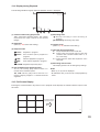
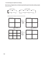
Multi-Segment Split- Screen Display ............................................................... 34
Sequence Display ............................................................................................ 35
Zoom Display ................................................................................................... 35
14. OTHER FUNCTIONS
14.1. Triplex Display ................................................................................................. 36
14.2. Position Setting Display ................................................................................... 37
15. RECORDING
15.1. Before Recording ............................................................................................. 38
15.1.1. Disk mode ............................................................................................ 38
15.1.2. Recording order to hard disks .............................................................. 38
15.1.3. Disk recording mode ............................................................................ 39
15.2. Recording Mode ............................................................................................... 39
15.3. Priority Recording ............................................................................................ 39
15.3.1. How to perform priority recording ......................................................... 39
15.4. Auto Recording (Alarm Event Recording and Normal Recording) ................... 40
15.4.1. Alarm event recording .......................................................................... 40
15.4.2. Normal recording ................................................................................. 41
15.5. Pre-Recording .................................................................................................. 41
15.6. Recording State ............................................................................................... 41
15.7. Recording Operation When Edge/Level Settings Are Performed .................... 43
15.8. Picture Quality .................................................................................................. 43
15.9. Recording Rate ................................................................................................ 44
15.10. Recording time ................................................................................................. 44
15.11. Available Disk Time and Operation .................................................................. 44
16. PLAYBACK
16.1. Type of Playback ............................................................................................. 45
16.2. How to Perform Playback ................................................................................ 45
16.2.1. Playback .............................................................................................. 45
16.2.2. Reverse playback ................................................................................ 45
16.2.3. Playback stop ....................................................................................... 45
16.2.4. Earliest image display .......................................................................... 46
16.2.5. Latest image reverse playback ............................................................ 46
16.2.6. Fast forward/reverse playback ............................................................. 46
16.2.7. Pause ................................................................................................... 46
16.2.8. Frame advance/frame reverse playback .............................................. 46
16.3. Event ................................................................................................................ 47
16.3.1. Instance event access ......................................................................... 47
3
17. SEARCH
17.1. Date/Time Search ............................................................................................ 48
17.2. Event Search ................................................................................................... 49
17.2.1. Event search list display ...................................................................... 50
18. ARCHIVE .............................................................................................................. 51
18.1.
18.2.
18.3.
18.4.
Archiving & Transfer Times .............................................................................. 52
Archiving by Entering the Date and Time ........................................................ 53
Archiving from the Playback Screen ................................................................ 54
Display During Archiving .................................................................................. 55
18.4.1. Display during archiving ....................................................................... 55
18.4.2. Archiving stop ...................................................................................... 55
18.4.3. Archiving completion ............................................................................ 55
18.4.4. About error messages .......................................................................... 56
18.5. When Viewing Saved Data .............................................................................. 57
18.5.1. PC Operating conditions and image data ............................................ 57
18.5.2. Folder Configuration and File Name .................................................... 57
18.5.3. Playback by way of viewer software .................................................... 58
18.5.4. Tampering/alteration check .................................................................. 59
19. ABOUT SECURITY SETTING
19.1. Securing the Digital Video Recorder's Operating Keys .................................... 60
19.1.1. Password and operation levels ............................................................ 61
19.2. Security Settings Using a USB Key ................................................................. 62
19.2.1. USB Key Level Settings and Operation Levels .................................... 62
19.2.2. USB Key registration ............................................................................ 62
19.2.3. Resetting the USB Key registration ..................................................... 63
19.3. Login and Logout by Password ........................................................................ 63
19.3.1. Password Entry .................................................................................... 63
19.3.2. When USB key settings are invalid... ................................................... 63
19.3.3. When USB key settings are valid... ...................................................... 64
19.4. Security Settings Against Remote External Access ......................................... 65
19.5. Security Settings Against Web Access ............................................................ 65
20. MALFUNCTION OPERATION
20.1. Stopping the Buzzer ......................................................................................... 66
20.2. Hard Disk Errors .............................................................................................. 66
20.2.1. "Playback stopped" warning display .................................................... 66
20.2.2. "Restart" warning display ..................................................................... 67
20.2.3. Checking hard disks when an error has occurred ................................ 67
20.2.4. If a hard disk error occurs .................................................................... 67
20.3. Video Loss ....................................................................................................... 68
20.3.1. If video loss occurs... ........................................................................... 68
20.4. Fan Malfunction ............................................................................................... 69
20.4.1. If a fan malfunction occurs.... ............................................................... 69
20.5. "Hard Disk Full" Warning ................................................................................. 69
20.5.1. If the hard disk becomes full.... ............................................................ 69
20.6. Operation Following Restoration From a Power Outage ................................. 70
20.6.1. Monitor display ..................................................................................... 70
20.6.2. Recording ............................................................................................. 70
4
SETTINGS
21. SETTING PROCEDURES AND ITEM LIST
21.1. Basic Setting Procedures ................................................................................. 71
21.2. Setting Item List ............................................................................................... 72
22. MAIN MENU SETTING
22.1. About the Main Menu Setting ........................................................................... 74
22.1.1. Saving setting ...................................................................................... 75
22.1.2. Implementing setting ............................................................................ 75
23. RECORDING SETTING ................................................................................... 76
23.1. Priority Recording Setting ................................................................................ 77
23.1.1. Recording setting ................................................................................. 78
23.2. Auto Recording Setting .................................................................................... 79
23.2.1. Schedule .............................................................................................. 79
23.2.2. Setting of groups A-F .......................................................................... 80
23.2.3. Special day setting ............................................................................... 83
23.2.4. Motion detection settings ..................................................................... 84
23.3. Pre-Recording Settings .................................................................................... 85
24. SCREEN DISPLAY SETTING ........................................................................ 86
24.1.
24.2.
24.3.
24.4.
24.5.
Character Display Settings .............................................................................. 87
Monitor Output Setting ..................................................................................... 88
Sequence Setting ............................................................................................. 88
Camera Name Setting ..................................................................................... 89
DVR Name Setting ........................................................................................... 89
25. NETWORK SETTING ....................................................................................... 90
26. MAIL SETTING ................................................................................................... 91
26.1. Transmission Condition Setting ....................................................................... 92
27. SYSTEM SETTING ............................................................................................ 93
27.1.
27.2.
27.3.
27.4.
I/O Terminal Mode Setting ............................................................................... 94
Control Output Terminal Setting ...................................................................... 95
Security Setting ................................................................................................ 96
Camera Preset Pattern Setting ........................................................................ 97
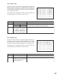
28. LOG DISPLAY
28.1. Recording Log .................................................................................................. 98
28.2. Failure Log ....................................................................................................... 99
28.3. System Log ...................................................................................................... 99
29. DATE/TIME SETTING .................................................................................... 100
30. EQUIPMENT MAINTENANCE .................................................................... 101
30.1. Hard Disk Drive Initialization .......................................................................... 102
5
WEB FUNCTIONS
31. WEB SERVER FUNCTIONS
31.1. About the Functions ....................................................................................... 103
31.2. System Requirements .................................................................................... 103
31.3. How to Log In ................................................................................................. 104
31.3.1. Access inhibit ..................................................................................... 104
31.4. Top Page ....................................................................................................... 105
31.4.1. For administrator account .................................................................. 105
31.4.2. For user account ................................................................................ 105
31.5. Menu Screen .................................................................................................. 106
31.5.1. Menu screen setting ........................................................................... 106
31.6. Live Image Transmission ............................................................................... 107
31.6.1. For administrator account .................................................................. 107
31.6.2. For user account ................................................................................ 107
31.6.3. Screen change button ........................................................................ 108
31.6.4. Camera control section ...................................................................... 108
31.7. Playback Transmission .................................................................................. 110
31.7.1. Playback Operations .......................................................................... 111
31.7.2. Searching ........................................................................................... 111
31.7.3. Download ........................................................................................... 112
31.7.4. Duplex display .................................................................................... 113
31.8. Remote control ............................................................................................... 114
31.9. Web Indication setting .................................................................................... 115
ADDITIONAL INFORMATION
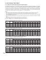
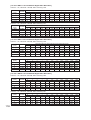
32. RECORDING TIME TABLE
32.1. About Picture Quality Settings During Recording .......................................... 116
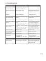
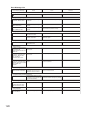
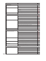
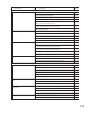
33. TROUBLESHOOTING ................................................................................... 119
34. INDEX ................................................................................................................... 121
35. SPECIFICATIONS ........................................................................................... 127
6
1. SAFETY PRECAUTIONS
• Before installation or use, be sure to carefully read all the instructions in this section for correct and safe
operation.
• Make sure to observe the instructions in this manual as the conventions of safety symbols and messages
regarded as very important precautions are included.
• We also recommend you keep this instruction manual handy for future reference.
Safety Symbol and Message Conventions
Safety symbols and messages described below are used in this manual to prevent bodily injury and property
damage which could result from mishandling. Before operating your product, read this manual first and
understand the safety symbols and messages so you are thoroughly aware of the potential safety hazards.
WARNING
Do not expose the unit to rain or an environment where it may be
splashed by water or other liquids, as doing so may result in fire or
electric shock.
WARNING
Indicates a potentially hazardous situation which, if mishandled, could
result in death or serious personal injury.
When Installing the Unit
• This is a class A product. In a domestic environment this product may cause radio interference in which case
the user may be required to take adequate measures.
• Use the unit only with the voltage specified on the unit. Using a voltage higher than that which is specified
may result in fire or electric shock.
• Do not cut, kink, otherwise damage nor modify the power supply cord. In addition, avoid using the power
cord in close proximity to heaters, and never place heavy objects -- including the unit itself -- on the power
cord, as doing so may result in fire or electric shock.
• Avoid installing or mounting the unit in unstable locations, such as on a rickety table or a slanted surface.
Doing so may result in the unit falling down and causing personal injury and/or property damage.
When the Unit is in Use
• If any of the following irregularities occurs, immediately switch off the power, disconnect the power supply
plug from the AC outlet and inform the shop from where the unit was purchased. Further using the unit may
result in fire or electric shock.
· If you detect smoke or a strange smell coming from the unit
· If water or any metallic object gets into the unit
· If the unit falls, or the unit case breaks
· If the power supply cord is damaged (exposure of the core, disconnection, etc.)
· If no image appears
• To prevent a fire or electric shock, never open the unit case nor modify the unit as there are high voltage
components inside the unit. Refer all servicing to your nearest TOA dealer.
• Do not place cups, bowls, or other containers of liquid or metallic objects on top of the unit. If they
accidentally spill into the unit, this may cause a fire or electric shock.
• Do not insert nor drop metallic objects or flammable materials in the ventilation slots of the unit's cover, as
this may result in fire or electric shock.
• Do not touch the power supply plug or control line during thunder and lightning, as this may result in electric
shock.
7
CAUTION
Indicates a potentially hazardous situation which, if mishandled, could
result in moderate or minor personal injury, and/or property damage.
When Installing the Unit
• Never plug in nor remove the power supply plug with wet hands, as doing so may cause electric shock.
• When unplugging the power supply cord, be sure to grasp the power supply plug; never pull on the cord
itself. Operating the unit with a damaged power supply cord may cause a fire or electric shock. When
removing the power cord, be sure to hold its plug to pull.
• When moving the unit, be sure to remove its power supply cord from the wall outlet. Moving the unit with the
power supply cord connected to the outlet may cause damage to the power supply cord, resulting in fire or
electric shock.
• Do not block the ventilation slots in the unit's cover. Doing so may cause heat to build up inside the unit and
result in fire.
• Avoid installing the unit in humid or dusty locations, in locations exposed to the direct sunlight, near the
heaters, or in locations generating sooty smoke or steam as doing otherwise may result in fire or electric
shock.
• Do not connect a network terminal exposed to excessive voltage to the 100BASE-TX terminal, Hard disk
expansion unit connection terminal or Remote control I/O terminal A, as doing so may result in fire or electric
shock.
When the Unit is in Use
• Do not place heavy objects on the unit as this may cause it to fall or break which may result in personal
injury and/or property damage. In addition, the object itself may fall off and cause injury and/or damage.
• Clean the unit periodically. Contact your TOA dealer regarding the cleaning. If dust is allowed to accumulate
in the unit over a long period of time, a fire may result.
• If dust accumulates on the power supply plug or in the wall AC outlet, a fire may result. Clean it periodically.
In addition, insert the plug in the wall outlet securely.
• Switch off the power, and disconnect the power supply plug from the AC outlet when cleaning or leaving the
unit unused for long periods of time. Doing otherwise may cause a fire or electric shock.
The equipment must be connected to an earthed mains socket-outlet.
-Finland
"Laite on liitettävä suojamaadoituskoskettimilla varustettuun pistorasiaan"
-Norway
"Apparatet må tilkoples jordet stikkontakt"
-Sweden
"Apparaten skall anslutas till jordat uttag"
8
CU version complies with Part 15 of the FCC Rules.
Note
This equipment has been tested and found to comply with the limits for a Class A digital device,
pursuant to Part 15 of the FCC Rules. These limits are designed to provide reasonable protection
against harmful interference when the equipment is operated in a commercial environment. This
equipment generates, uses, and can radiate radio frequency energy and, if not installed and used in
accordance with the instruction manual, may cause harmful interference to radio communications.
Operation of this equipment in a residential area is likely to cause harmful interference in which case the
user will be required to correct the interference at his own expense.
Modifications
Any modifications made to this device that are not approved by TOA Corporation may void the authority
granted to the user by the FCC to operate this equipment.
This equipment is classified as a LASER CLASS 1 PRODUCT. The following classification label is located on
the drive.
CLASS 1 LASER PRODUCT
CAUTION:
INVISIBLE LASER RADIATION WHEN OPEN.
AVOID EXPOSURE TO BEAM.
9
2. HANDLING PRECAUTIONS
• The supplied power supply cord is designed for exclusive use with the Digital Video Recorder. Never use it
with other equipment.
• Do not connect the10BASE-T/100BASE-TX terminal, Hard disk expansion unit connection terminal or
Remote control I/O terminal A to networks that could be exposed to excessive electrical voltage. Failure to
follow this instruction could result in electric shock or fire.
• It is recommended that the Recorder be always used in locations where the ambient temperature ranges
from +5°C to +40°C (41°F to 104°F) and humidity levels of less than 80% to ensure that no condensation is
formed.
• When moving the Recorder, first disconnect its power supply plug from the AC outlet and then wait at least
30 seconds before moving.
• Avoid moving the Recorder suddenly from a cold location to a warm location, or installing it in close
proximity to an air-conditioner outlet, as internal condensation could result. When condensation occurs, do
not switch on the power until the Recorder has sufficiently dried. Also, when brought into a warm room from
the cold outdoors, be sure to leave it unused for at least half a day before using it.
• Avoid installing the Recorder in humid or dusty locations, or in locations exposed to direct sunlight, sooty
smoke or steam. Note that even in locations which are not particularly dusty, dust may accumulate at the
Recorder’s ventilation slots. Because this could cause an extreme rise in temperature inside the Recorder,
be sure to clean the ventilation slots periodically after switching off the power and disconnecting the power
supply plug from the AC outlet. It is highly recommended that the ventilation slots be cleaned once a year.
• When cleaning the Recorder, be sure to switch off the power. Wipe with a soft dry cloth. If it gets very dirty,
use the soft cloth slightly moistened in neutral cleanser. Never use volatile spirits like thinner, benzine, or
alcohol. Such chemicals may damage its plastic surface.
• Do not block the ventilation slots or cooling fan, which could cause the temperature inside the Recorder to
rise, possibly resulting in unit failure. Install the Recorder at least 100 mm (3.9 inch) away from the nearest
wall surface.
• Since the Recorder is equipped with a cooling fan, a motor sound is generated. Avoid installing the Digital
Video Recorder in locations which resonate electrical motor noise.
• Do not install the Recorder in locations influenced by strong electrical or magnetic fields, as monitor screen
pictures may become distorted or the Recorder could fail.
• The Recorder can be used only in a commercial and industrial area. Operation of this equipment in a
residential area is likely to cause radio disturbance and TV interference.
• Avoid jarring or striking the Recorder. The Recorder is a piece of precision equipment and accidentally
dropping it or subjecting it to strong impacts could cause its failure. When transporting the Recorder,
carefully pack it in the supplied carton to protect it from shock.
• Avoid using the Recorder in locations exposed to vibration. The Recorder is a piece of precision equipment,
as this may cause the unit malfunction.
• Avoid installing the Recorder vertically or tilting it at extreme angles, since it is designed to be used in a
horizontal position only.
• About the hard disks
• If the hard disk fails, recorded data cannot be restored.
• Save important recordings to DVD-R/RW disks.
• Recordings copied from video images or video recordings with registered copyrights may not be used for
commercial purposes other than for private use without express permission from the copyright holder.
10
• TOA takes no responsibility for any incidental damage, such as loss of sales opportunities, that may result.
• Avoid using the camera in line-locked mode. Failure to do so may cause the displayed camera images to
flicker. Also, video may be lost if power frequency fluctuates significantly.
3. GLOSSARY OF TERMS
Triplex
This function permits recording while viewing live and recorded images in multi-screen display. In Triplex
setting, individual live or recorded images can be set to be displayed on individual split-screen segments.
Pre-Recording
Retroactive recordings can be made for up to 5 minutes before the occurrence of an alarm event (alarm signal
input or motion movement) or priority recording, even if no recording is currently in progress.
Mirror Recording
Recording can be simultaneously made on 2 hard disks. Even if one hard disk should fail, the other hard disk
continues to record or play back.
Master and Slave Units
When synchronizing the Digital Video Recorders, one can be designated as a master unit, which can be used
to control the other slave units.
Normal Mode
When the first hard disk finishes recording, the second hard disk automatically begins to record. When the
settings (recording rate and picture quality) of both normal and mirror modes are set to be identical, the
recording time for normal mode is twice that of mirror mode.
Alarm Event Recording
Refers to both alarm recording and motion detected recording. Alarm recording is performed when the alarm
input terminal of the Digital Video Recorder or Combination Camera receives a signal. Motion detected
recording begins when movement is detected in the camera image.
Recording Rate (IPS)
Refers to the number of image frames to be recorded per second. The unit is IPS. The larger IPS value is, the
shorter recording intervals can become.
Event
Recording data from the start to the end of recording mode (Priority recording, Alarm Event recording and
Normal recording) is expressed as one event.
Post time
Set the time until the hard disk finished recording.
Schedule
The Digital Video Recorder’s auto-recording mode allows recording to be made according to a preset
schedule.
Live mode
Mode displaying current live camera images.
Playback mode
Mode displaying recorded camera images.
11
4. GENERAL DESCRIPTION
TOA's C-DR Series Digital Video Recorders feature a digital compression method that permits camera images
to be recorded on an internal hard disk. The C-DR091 Series is designed for 9 channels, while the C-DR161
Series can be used for up to 16 channels.
It can simultaneously play back recorded camera images while continuing to record images onto the hard
disk.
Mounting in EIA-Standard equipment racks can also be easily performed with the addition of optional rack
mounting brackets.
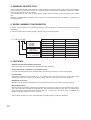
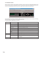
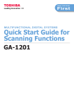
5. MODEL NUMBER CONFIGURATION
A total of 16 type variations are available depending on the combination of hard disk capacity and DVD drive
availability.
For model numbers and hard disk capacity, please refer to the following table.
C- DR161D08
08 : 80 GB
1 : 160 GB
3 : 320 GB
6 : 600 GB
D : With DVD
- : Without DVD
09 : for 9 channels
16 : for 16 channels
9 channels
C-DR091D08
C-DR091-08
C-DR091D1
C-DR091-1
C-DR091D3
C-DR091-3
C-DR091D6
C-DR091-6
16 channels
C-DR161D08
C-DR161-08
C-DR161D1
C-DR161-1
C-DR161D3
C-DR161-3
C-DR161D6
C-DR161-6
Hard disk capacity
80 GB × 1
80 GB × 1
160 GB × 1
160 GB × 1
160 GB × 2
160 GB × 2
300 GB × 2
300 GB × 2
6. FEATURES
• Simultaneous Recording/Playback Function
Recorded images can be played back without interrupting recording.
• Triplex (Recording + Playback + Live Image) Function
Live and recorded images can be simultaneously viewed during recording in multi-screen display.
• Pre-Recording
Retroactive recordings can be made for up to 5 minutes before the occurrence of an alarm event (alarm
signal input or motion movement) or priority recording, even if no recording is currently in progress.
• Speed Search Function
Date/time Search and Event Search functions permit desired scenes to be quickly found and viewed.
• Mirroring Recording
Mirroring Recording function performs the simultaneous recording of data onto the two hard disks. Even if
one of the disks fails, recording and playback can still be performed using the other disk. For models with a
single hard disk (versions with model number suffix -08, -1, D08 or D1), the mirror mode is available only
when the hard disk expansion unit is connected.
The possibility of data loss due to hard disk failure is greatly reduced, increasing reliability.
12
• High Picture Quality and High Frame Rate
Recording and playback can be simultaneously performed at a maximum of 120 IPS. (Image compression
method: Motion-JPEG.) Picture quality can be adjusted in five levels, allowing high quality recording or
extended recording according to the intended purpose of use. Picture quality and recording intervals can be
freely set for individual cameras and recording system.
• Auto-recording
The Digital Video Recorder starts recording shortly after power on and makes recordings by preset
schedule. The auto-recording function permits Normal recording and Alarm event recording, for each of
which different setting can be performed. (Refer to p. 79; Auto-recording setting.)
• Network Function
Use this function to remotely monitor or control cameras connected to the Digital Video Recorder, or search
or play back their recorded images on a PC web browser.
• Email Function
Email can be transmitted when an alarm event or failure occurs. Up to 4 destination addresses can be
programmed.
• Cascade Connections
Cascade-connecting 8 Digital Video Recorders permits camera images of up to 128 cameras to be viewed
on a single monitor display. Up to 4 C-RM1000 Remote Controllers can be connected in a system, allowing
each controller to control all Digital Video Recorders and Combination Cameras. (Refer to p. 20;
Connections.)
• Archive Function
Recorded images can be copied onto the DVD-R/RW (available to model with DVD) or to the USB memory.
Viewer software is also downloaded at the same time. (Refer to p. 51; Archive.)
• Security Function
Two security settings, using a password and USB key lock, are made available. The use of both methods
ensures the highest security. (Refer to p. 60; About security setting.)
• Hard disk expansion
Up to 2 Hard Disk Expansion units of C-DA1000-1 (1.2 TB) and/or C-DA1000-2 (2.4 TB) can be connected
per Digital Video Recorder. UP to 4.8 TB can be added to the Digital Video Recorder’s hard disk capacity.
13
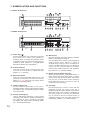
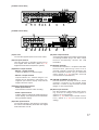
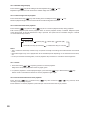
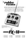
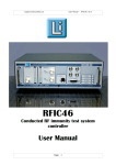
7. NOMENCLATURE AND FUNCTIONS
[ C-DR161 Series Front ]
9 11
7
20
19
18
5
2
14
DVD
ARCHIVE
1
2
3
4
5
6
7
8
PRIORITY
REC
KEY LOCK
9
10
11
12
13
14
15
16
MONITOR 1
BUZZER STOP/
ALARM RESET
ZOOM
SEARCH
MENU/
ENTER
MULTI
SCREEN
SEQUENCE
REC
FAILURE
HD FULL
MONITOR 2
DIGITAL VIDEO RECORDER C-DR161
3
8
6
4
10 12
13 15 16
17
1
[ C-DR091 Series Front ]
5
20
19
18
2
9 11
7
14
DVD
ARCHIVE
1
2
3
4
5
6
7
8
9
KEY LOCK
PRIORITY
REC
MONITOR 1
BUZZER STOP/
ALARM RESET
ZOOM
SEARCH
MENU/
ENTER
MULTI
SCREEN
SEQUENCE
REC
FAILURE
HD FULL
MONITOR 2
DIGITAL VIDEO RECORDER C-DR091
3
4
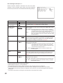
(1) Power key [
]
Pressing the Power key changes the Digital
Video Recorder's mode from standby to
operation mode. To switch from operation mode
to standby mode, hold down the Power key for 2
seconds or more. (Refer to p. 26; Digital Video
Recorder Activation and Termination.)
(2) Archive Terminal
Use this terminal when copying video data
recorded on a hard disk to a USB memory.
(Refer to p. 51; Archive.)
(3) Key lock terminal
Insert the preprogrammed USB key into this
terminal to cancel the security lock setting.
(Refer to p. 60; Securing the Digital Video
Recorder's Operating Keys.)
(4) Camera selector key
Selects cameras displayed on the live or
playback screens. Pressing the Camera selector
key displays the corresponding camera image
on the full screen.
(5) Priority recording key
Used to start priority recording. To stop priority
recording, hold down the Priority recording key
for 2 seconds or more. The Priority recording
key flashes red during priority recording. (Refer
to p. 39; Priority Recording.)
14
6
8
10 12
13 15 16
17
1
(6) Monitor key
Use this key when switching operation between
Monitor 1 and Monitor 2 outputs.
This key lights when pressed, and extinguishes
when pressed again. Monitor 1 output is
enabled when the key is unlit, and Monitor 2
output is enabled when the key is lit. Monitor 2
output can be operated with the Camera
selector keys, Multi-screen key, and Sequence
key. (Refer to p. 31; Monitor display.)
(7) Buzzer stop key (Alarm reset key)
When priority recording, equipment failure, or
alarm event recording takes place, a buzzer
sounds. Pressing this key disables the buzzer.
Use this key to reset alarm event recording.
Hold down this key for 2 seconds or more to
reset alarm event recording.
(8) Zoom key
Use the Zoom key to zoom in on the live and
playback screens (2x zoom). If this key is
pressed during full-screen display, the cursor for
determining the zoom position is displayed. If
the zoom position is confirmed and the Menu
key is pressed, the 2X zoomed screen is
displayed. Pressing this key again cancels the
zoom mode. (Refer to p. 35; Zoom Display.)
(9) Search key
Use this key to search for recorded images. If
the Search key is pressed when the live or
playback screen is displayed, the search screen
is displayed. To exit the search screen, press
the [
] key. (Refer to p. 48; Search.)
(10) Multi-Screen / [-] Key
• Multi-screen display
Displays live or recorded camera images on
the multi-segment split screen. The screen
switches to 4-segment, 9-segment and 16segment split screen displays with each
depression of this key. (Refer to p. 34; MultiSegment Split-Screen Display.)
• Reverse setting value selection [-]
Pressing this key while setting values are
selected on the menu screen varies setting
values in the reverse direction.
• Triplex setting screen activation
If the Multi-Screen key is continuously pressed
for 2 seconds or more while the multi-segment
split screen is displayed, the Triplex setting
screen is displayed. To exit the Setting screen,
hold down the Menu key for 2 seconds or
more. (Refer to p. 36; Triplex display.)
• Position setting screen activation
If the Multi-screen key is continuously pressed
for 2 seconds or more while multi-split screen is
displayed in the Live mode, the Position setting
screen is displayed. To exit the Setting screen,
hold down the Menu key for 2 seconds or
more. (Refer to p. 37; Position setting display.)
(11) Menu key
• Activating the Menu screen
Holding down the Menu key for 2 seconds or
more when the Monitor key remains unlit
displays the menu screen on the Monitor 1
screen. To return to live mode, press the [
] key. (Refer to p. 74; Main menu setting.)
• Menu item confirmation
Use this key when confirming selected setting
items on the menu screen, such as "Yes," "No"
or "Execute." (Refer to p. 74; Main menu
setting.)
• Advancing to the next menu setting screen
Press this key when advancing from the
position indicated by the
mark on the
menu setting screen to the next menu setting
screen. (Refer to p. 74; Main menu setting.)
• Exiting the motion setting screen
Hold down the Menu key for 2 seconds or
more to exit the motion detection setting on the
menu screen. (Refer to p. 84; Motion detection
settings.)
• Activating the Password entry screen
Holding down the Menu key for 2 seconds or
more when the Security setting is activated
displays the Password entry screen. (Refer to
p. 96; Security setting.)
(12) Sequence/ [ + ] Key
• Sequence
Pressing the Sequence key in live mode
causes the camera outputs to be displayed in
preprogrammed sequential order. (Refer to p.
35; Sequence Display.)
• Forwarding [+] the setting value
Pressing the setting value on the Menu screen
during selection changes the setting value in
forward direction.
(13) Reverse playback [
] key
• Reverse playback
Images are played back in reverse if the
Reverse playback key is pressed. (Refer to p.
45; Playback.)
• Moving the cursor to the left on the menu
screen
Use this key to move the cursor to the left on
the menu screen.
• Returning the Menu screen to the previous
screen
Pressing the [
] key when the cursor
positions to the left on the Menu screen returns
the display to the previous screen.
• Returning to the live mode
Pressing the [
] key on the Menu screen
returns the display to the live mode.
(14) Pause [
,
] key
• Pause of playback/reverse playback screens
Use this key to temporarily stop the playback
display. Operation can be performed for the
archive menu display, frame advance/reverse
playback, and instant event access playback
while the display is temporarily stopped. (Refer
to p. 51; Archive.) (Refer to p. 45; Playback.)
• Moving the cursor upward on the Menu
screen
Used this key to move the cursor upward on
the Menu screen.
(15) Stop [
,
] key
• Stop of playback/reverse playback
Use this key to stop playback or reverse
playback. (Refer to p. 45; Playback.)
Note
Recording does not stop even if the Stop key
is pressed.
15
• Moving the cursor downward on the Menu
screen
Use this key to move the cursor downward on
the Menu screen.
(16) Playback [
] key
Pressing the Playback key plays back recorded
images. (Refer to p. 45; Playback.)
• Moving the cursor to the right on the Menu
screen
Use this key to move the cursor to the right on
the Menu screen.
(17) Informational Indicator
• Recording indicator
Lights during recording (Priority recording,
Normal recording, Alarm Event recording)
• Failure indicator
Flashes when video is lost or when a fan or
hard disk failure occurs. Refer to the failure log
on the menu screen for the cause of each
equipment failure. The LED flashes until the
Recorder returns to normal state.
• Available hard disk space indicator
Flashes when the available disk space falls
below the specified warning level while in write
protect mode and when the available disk
spaces runs out of time. This indicator does
not light (flash) while in overwrite mode.
(Refer to p. 93; System setting.)
16
(18) DVD indicator
Flashes when the DVD-R/RW is inserted and
while the inserted disk is being recognized, and
continuously lights while the disk is being
written.
(19) DVD receptacle
Place a DVD-R/RW here when copying data
recorded on the Digital Video Recorder.
(20) DVD eject Key
Use this key to insert or eject a DVD-R/RW.
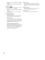
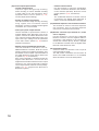
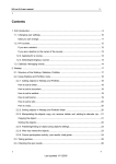
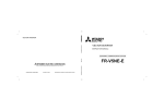
[C-DR161 series Rear]
25
32 33
31
RM
TERMINATION
ON
OFF
IN
1
2
3
4
5
6
7
8
9
10
11
12
13
14
15
16
2 RM IN-A
DISK ARRAY
1
OUT
VIDEO
AC MAINS
LINK
1
2
MONITOR OUT
IN
OUT
AUDIO
RS-232C
1
G
2
9
G 10
G
3
G 11
G
ALARM IN
4 G 5 G
G 12
G 13
6
G 14
G
7
G 15
8
G
PRIORITY
NC
IN G
G 16
G
1
G
G
2
CAMERA
+
G CONTROL OUT
G 3
G
+
RM IN-B
G -
4
G
IN
RM OUT-B
+
G TIME SYNC
G OUT G
SER.
DIGITAL VIDEO RECORDER
model C-DR161D3 CU
110-120V
50/60Hz mA
TOA Corporation
100BASE-TX
MADE IN JAPAN
22
21
24
23
27
26
30
29
28
[C-DR091 series Rear]
25
32 33
31
RM
TERMINATION
ON
OFF
IN
1
2
3
4
5
6
7
8
9
1
2 RM IN-A
DISK ARRAY
OUT
VIDEO
AC MAINS
LINK
1
2
MONITOR OUT
IN
OUT
AUDIO
RS-232C
1
G
9
G
2
G
3
G
ALARM IN
4 G 5 G
6
G
7
G
8
G
PRIORITY
NC
IN G
1
G
2
CAMERA
+
G CONTROL OUT
G 3
G
+
RM IN-B
G -
4
G
IN
RM OUT-B
+
G TIME SYNC
G OUT G
SER.
DIGITAL VIDEO RECORDER
model C-DR091D3 CU
110-120V
50/60Hz mA
TOA Corporation
100BASE-TX
MADE IN JAPAN
21
22
23
24
26
27
(21) AC inlet
Connect the supplied power cord to this socket.
(22) Link input terminal
Use this terminal to cascade-connect two or
more Digital Video Recorders. (Refer to p. 21;
Digital Video Recorder's Expansion system.)
(23) Monitor output terminal
• Monitor 1 output terminal
Outputs the Monitor 1's camera images.
• Monitor 2 output terminal
Outputs Monitor 2’s camera images. Live
images can be displayed in full-screen or 4segment split-screen display. Reproduced
images cannot be output.
(24) Audio input/output terminal
• Audio input terminal
This terminal is used for audio recording.
• Audio output terminal
Outputs audio input terminal signals during live
screen display, and outputs the recorded audio
during playback display.
28
29
30
(26) Video output terminal
A loop through output for the Video input terminal.
Connecting the BNC plug to the Video output
terminal automatically cancels the 75Ω
termination.
(27) RS-232C terminal
Connect this terminal to a computer’s RS-232C
terminal when performing control from a
personal computer. Connect this terminal to the
PC's RS-232C terminal using a nullmodem
cable. (Refer to p. 23; RS-232C Terminal
communications specifications.)
(28) 10BASE-T/100BASE-TX terminal
Use this terminal to remotely monitor or control
cameras connected to the Digital Video
Recorder, or search or play back their recorded
images on a PC web browser.
(29) Alarm input terminal
Use this terminal to make Alarm event recording. Connect no-voltage contact signals of
sensors, etc. to this terminal.
(Refer to p. 24; Alarm Input Terminal Connections.) (Refer to p. 94; I/O Terminal mode
setting.)
(25) Video input terminal
Connect the camera to this terminal. Connecting
the camera automatically terminates the Digital
Video Recorder at 75 Ω.
17
(30) Control input/output terminal
• Control output terminal
Outputs a signal during priority recording,
alarm recording or motion detected recording
or when video is lost, the hard disk is full or
equipment failure occurs. (Refer to p. 95;
Control output terminal setting.)
• Priority recording input terminal
Use this terminal to begin Priority recording
using signals from connected external
equipment. Connect no-voltage contact signals
of switches, etc. to this terminal.
• Time sync input & output terminal
Use this terminal to synchronize the clocks of
multiple Digital Video Recorders used in the
system. Connect the master Recorder's Time
sync output to the slave Recorder's Time sync
input. Time sync settings must be performed
on the menu screen. (Refer to p. 23; External
terminal connections.)
• Remote Control Input/Output Terminal B
Use this terminal for connection of the CRM1000 Remote Controller. Note the correct
polarity (positive and negative orientation). Use
the Remote control input & output terminal B if
the cable distance is longer than 3 meters (9.8
ft). (Refer to p. 20; Connections)
Also use this terminal to cascade-connect the
Digital Video Recorder. Connect the first
Digital Video Recorder's Remote control output
terminal to the second Recorder's Remote
control input terminal. Note the correct polarity.
(Refer to p. 21; Digital Video Recorder's
Expansion system.)
18
• Camera control terminal
Use this terminal to control the Combination
Camera. Connect this terminal to the camera's
control terminal (RS-485). Note the correct
polarity. (Refer to p. 20; Connections)
Note
The C-RM1000 Remote Controller must be
connected to the Digital Video Recorder in
order to control the Combination Camera.
(31) Hard disk expansion unit connection terminal
This terminal is used for hard disk expansion
unit connection. Up to 2 hard disk expansion
units can be connected to this terminal.
(32) Remote controller input terminal A ( Power
can be supplied.)
Use this terminal to connect the C-RM1000
Remote Controller. Use the supplied cable for
connection if the distance to the controller is
shorter than 3 meters (9.8 ft). Power is supplied
to the Remote Controller from the Digital Video
Recorder if this terminal is used.
(33) Termination switch
Terminal switch for Remote Control input &
output terminals A and B.
The ON position terminates the connection at
220Ω. The 220Ω termination is not available
when this switch is set to the OFF position.
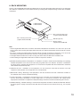
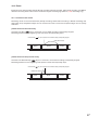
8. RACK MOUNTING
Use the optional MB-23B Rack Mounting Bracket when mounting the Digital Video Recorder in an equipment
rack. Remove 4 rubber feet on the bottom surface by loosening their respective fixing screws with a standard
screwdriver.
C-DR091 Series
C-DR161 Series
M4 x 12 binding head screw
(supplied with the MB-23B)
M5 x 12 binding head screw
(supplied with the MB-23B)
MB-23B (optional)
M5 fiber washer
(supplied with the MB-23B)
Note
• Use the Digital Video Recorder in locations with ambient temperature of between +5°C and +40°C (41°F and
104°F). When rack-mounting the Digital Video Recorder, the ambient temperature must be kept 35°C (95°F)
or below.
• Be sure to mount the Digital Video Recorder below the heat generating components, and mount the
perforated panel between the Recorder and such a heat generating component as required.
• The Digital Video Recorder has a built-in cooling fan. Never block the Recorder’s ventilation slot.
• Avoid installing the Digital Video Recorder in locations exposed to vibration.
a) Elevated Operating Ambient Temperature - If installed in a closed or multi-unit rack assembly, the operating
ambient temperature of the rack environment may be greater than room ambient. Therefore, consideration
should be given to installing the equipment in an environment compatible with the manufacturer's maximum
rated ambient temperature (Tmra).
b) Reduced Air Flow - Installation of the equipment in a rack should be such that the amount of air flow
required for safe operation of the equipment is not compromised.
c) Mechanical Loading - Mounting of the equipment in the rack should be such that a hazardous condition is
not achieved due to uneven mechanical loading.
d) Circuit Overloading - Consideration should be given to the connection of the equipment to the supply circuit
and the effect that overloading of circuits might have on overcurrent protection and supply wiring.
Appropriate consideration of equipment nameplate ratings should be used when addressing this concern.
e) Reliable Earthing - Reliable earthing of rack-mounted equipment should be maintained. Particular attention
should be given to supply connections other than direct connections to the branch circuit (e.g., use of power
strips).
19
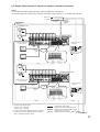
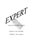
9. CONNECTIONS
9.1. Basic System
Combination camera
*2
HDD Expansion Unit
C-DA1000-2
HDD Expansion Unit
C-DA1000-2
To AC Mains
*2
RS-485
Color camera
DISK
ARRAY
RM
TERMINATION
ON
OFF
IN
1
2
3
4
5
6
7
8
9
10
11
12
13
14
15
16
1
2 RM IN-A
DISK ARRAY
RM IN-A
OUT
*
1
VIDEO
AC MAINS
Digital Video Recorder
C-DR161 Series
LINK
MONITOR
OUT1
1
2
MONITOR OUT
IN
OUT
AUDIO
RS-232C
1
G
9
G 10
2
G
3
G 11
G
ALARM IN
4 G 5 G
G 12
G 13
6
G 14
G
7
G 15
8
G
PRIORITY
NC
IN G
G 16
G
1
G
G
2
CAMERA
+
G CONTROL OUT
G 3
G
+
RM IN-B
G -
4
G
IN
RM OUT-B
+
G TIME SYNC
G OUT G
100BASE-TX
MONITOR
OUT2
10BASE-T/
100BASE-TX
Monitor 1
DVR CONTROL
OUTPUT-A
Live only
LAN
Monitor 2
PRIORITY
IN G
1
G
CAMERA
NC
+ G CONTROL OUT
2
G 3
G
RM OUT-B
+ G TIME SYNC
IN G OUT G
RM IN-B
+ G 4
G
Remote Controller
C-RM1000
PC
CAMERA
+GRS-485
*
1
*2
C-DR091 and C-DR161 Series
C-DR091: 9 I/ O Terminals
C-DR161: 16 I/ O Terminals
Match the Combination Camera’ s address to the Digital Video
Recorder’ s video input number.
: Coaxial cable (Video signal)
: CPEV-S 0.65-3C (RS-485 Control line)
Twisted pair with shield 22AWG or larger
: Modular cable, 3 m (9.8 ft).
(supplied with the C-RM1000)
: Modular cable, 1 m (3.3 ft)
(supplied with HDD expansion unit)
: S-ATA cable, 1 m (3.3 ft)
(supplied with HDD expansion unit)
9.2. About Star Wiring
A C-IF500 Interface Unit is required when using star wiring for a Combination Camera’s control lines (RS485). Refer to the Interface Unit’s instruction manual for specific details on control line connections.
20
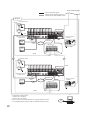
9.3. Digital Video Recorder’s Expansion System (Cascade connection)
Notes
• A cascade-connected system generally requires the Remote Controller(s).
• It is necessary to set DVR-ID in the cascade-connected system. (Refer to p. 27; Setting the DVR -ID.)
Interface unit
C-RF1000
1
REMOTE CONTROLLER
2
3
4
POWER/DVR
INTERFACE UNIT C-RF1000
REMOTE
CONTROLLER
INPUT-B
DVR CONTROL
OUTPUT-A
Group 1
RS-485
Combination camera
To AC Mains
Termination: OFF
RM IN-A
RM
TERMINATION
ON
OFF
IN
1
2
3
4
5
6
7
8
9
10
11
12
13
14
15
16
1
LINK
DISK ARRAY
*2
2 RM IN-A
OUT
VIDEO
AC MAINS
1
G
9
G 10
2
G
3
ALARM IN
4 G 5 G
G
G 11
G 12
G 13
6
G
G 14
7
8
G
PRIORITY
NC
IN G
G 16
G
1
G
G 15
G
CAMERA
+
G CONTROL OUT
G 3
G
2
RM IN-B
+
G 4
RM OUT-B
+
G TIME SYNC
IN G OUT G
G
*1
Digital Video Recorder 1
C-DR161 Series
1
2
MONITOR OUT
LINK
IN
OUT
AUDIO
RS-232C
10BASE-T/
100BASE-TX
MONITOR
OUT 1
Group 1
Master
Monitor
To LAN
MONITOR
OUT 2
Monitor 1
Remote Controller 1
C-RM1000
100BASE-TX
PRIORITY
IN G
1
CAMERA
+ G CONTROL OUT
G 3
G
NC
G
2
RM IN-B
+ G 4
G
IN
RM OUT-B
+ G TIME SYNC
G OUT G
AC adaptor
Live only
RM
OUT-B
CAMERA
+G-
Monitor 2
RS-485
To AC Mains
Termination: OFF
1
2
3
4
5
6
7
8
9
10
11
12
13
14
15
16
RS-485
RM
TERMINATION
ON
OFF
IN
1
DISK ARRAY
2 RM IN-A
OUT
VIDEO
AC MAINS
*1
Digital Video Recorder 2
C-DR161 Series
LINK
1
2
MONITOR OUT
IN
OUT
AUDIO
RS-232C
1
G
9
G 10
2
G
3
G 11
G
ALARM IN
4 G 5 G
G 12
G 13
6
G 14
G
7
8
G
PRIORITY
NC
IN G
G 16
G
1
G
G 15
G
2
CAMERA
+
G CONTROL OUT
G 3
G
+
RM IN-B
G -
4
G
IN
RM OUT-B
+
G TIME SYNC
G OUT G
*2
100BASE-TX
10BASE-T/
100BASE-TX
MONITOR
OUT 1
Remote Controller 2
C-RM1000
To LAN
Live only
RM IN-B
MONITOR
OUT 2
Monitor 2
PRIORITY
IN G
1
G
NC
2
CAMERA
+G-
CAMERA
+ G CONTROL OUT
G 3
G
RM IN-B
+ G 4
G
IN
RM OUT-B
+ G TIME SYNC
G OUT G
RM
OUT-B
RS-485
*1
*2
RS-485
C-DR091 and C-DR161 Series
C-DR091: 9 I/ O Terminals
C-DR161: 16 I/ O Terminals
: Coaxial cable (Video signal)
For the maximum cable length between the C-RF1000
Interface Unit and the C-RM1000 Remote Controller,
refer to C-RM1000 operation manual.
: Modular cable, 3 m (9.8 ft)
(supplied with the C-RF1000)
: CPEV-S 0.65-3C (RS-485 Control line)
Twisted pair with shield 22AWG or larger
To next page
21
From previous page
: Coaxial cable (Video signal)
: CPEV-S 0.65-3C (RS-485 Control line)
Twisted pair with shield 22AWG or larger
Group 2
RS-485
Combination camera
To AC Mains
Termination: OFF
RM
TERMINATION
ON
OFF
IN
1
2
3
4
5
6
7
8
9
10
11
12
13
14
15
16
1
LINK
DISK ARRAY
2 RM IN-A
OUT
VIDEO
AC MAINS
1
G
9
G 10
2
G
3
G
G 11
ALARM IN
4 G 5 G
G 12
G 13
6
G
G 14
7
8
G
PRIORITY
NC
IN G
G 16
G
1
G
G 15
G
2
CAMERA
+
G CONTROL OUT
G 3
G
+
RM IN-B
G -
4
G
*2
RM OUT-B
+
G TIME SYNC
G OUT G
IN
*1
Digital Video Recorder 3
C-DR161 Series
LINK
1
2
MONITOR OUT
IN
OUT
AUDIO
RS-232C
10BASE-T/
100BASE-TX
MONITOR
OUT 1
Group 2
Master
Monitor
MONITOR
OUT 2
Monitor 1
Remote Controller 3
C-RM1000
100BASE-TX
To LAN
RM IN-B
PRIORITY
IN G
1
CAMERA
+ G CONTROL OUT
G 3
G
NC
G
2
RM IN-B
+ G 4
G
IN
RM OUT-B
+ G TIME SYNC
G OUT G
AC adaptor
Live only
RM
OUT-B
CAMERA
+G-
Monitor 2
RS-485
Combination camera
RS-485
Termination: ON
RM
TERMINATION
ON
OFF
IN
1
2
3
4
5
6
7
8
9
10
11
12
13
14
15
16
1
DISK ARRAY
2 RM IN-A
OUT
VIDEO
*1
Digital Video Recorder 8
C-DR161 Series
AC MAINS
LINK
1
2
MONITOR OUT
IN
OUT
AUDIO
RS-232C
1
G
9
G 10
2
G
3
G 11
G
ALARM IN
4 G 5 G
G 12
G 13
6
G 14
G
7
G 15
8
G
PRIORITY
NC
IN G
G 16
G
1
G
G
2
CAMERA
+
G CONTROL OUT
G 3
G
+
RM IN-B
G -
4
G
IN
RM OUT-B
+
G TIME SYNC
G OUT G
100BASE-TX
10BASE-T/
100BASE-TX
MONITOR
OUT 1
Remote Controller 4
C-RM1000
To LAN
Live only
MONITOR
OUT 2
Monitor 2
*2
RM IN-B
PRIORITY
IN G
1
G
NC
2
CAMERA
+ G CONTROL OUT
G 3
G
RM IN-B
+ G 4
G
IN
RM OUT-B
+ G TIME SYNC
G OUT G
CAMERA
+GRS-485
22
*1
C-DR091 and C-DR161 Series
C-DR091: 9 I/ O Terminals
C-DR161: 16 I/ O Terminals
*2
For the maximum cable length between the C-RF1000 Interface Unit and
the C-RM1000 Remote Controller, refer to C-RM1000 operation manual.
PC
LAN
10. EXTERNAL TERMINAL CONNECTIONS
10.1. RS-232C Terminal Communications Specifications
The Digital Video Recorder can be controlled by a PC or other equipment via a connection through the RS232C port. However:
Notes
• Control software is not available as standard accessory.
• TOA takes no responsibility for hardware or software failures or damages resulting from the use of thirdparty control software.
10.1.1. Communications protocol
Transfer System: Start/stop system
Parity Bit: Even number
Transfer Speed: 9,600 bps, 19,200 bps, and 38,400 bps
Code: Binary code
Bit Length: 8 bits
Flow Control: CTS/RTS handshake or none
Stop Bit: 1
Error Control: None
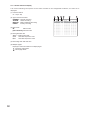
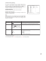
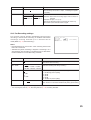
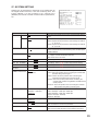
10.1.2. RS-232C Connector pin arrangement
The following signal names are assigned to each pin of the RS-232C D-sub 9P male connector:
Terminal No.
1
2
3
4
5
6
7
8
9
Symbol
NC
RD
SD
NC
SG
NC
RS
CS
NC
Name
Not connected
Receiving data
Sending data
Not connected
Signal ground
Not connected
Request to send
Clear to send
Not connected
1
5
6
9
Note
RS-232C connector plug is supplied with the Digital Video Recorder.
For RS-232C connection to PC, use null modem cable.
23
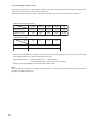
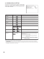
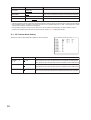
10.2. Alarm Input Terminal Connections
The number of terminals available differs depending on whether the Digital Video Recorder is a 9-channel or a
16-channel version. Refer to the table below when making alarm input terminal connections.(Refer to p. 14;
Nomenclature and Functions)
For 16 channel
1
G
9
G 10
Terminal name
1
G
2
G
3
G
4
G
5
G
6
G
7
G
8
G
2
G
3
G 11
G
ALARM IN
4 G 5 G
G 12
G 13
Symbol
ALARM 1
GND
ALARM 2
GND
ALARM 3
GND
ALARM 4
GND
ALARM 5
GNA
ALARM 6
GND
ALARM 7
GND
ALARM 8
GND
6
G 14
G
For 9 channel
7
G 15
G
8
G
1
G
G 16
G
9
G
Name
Alarm input 1
Signal ground
Alarm input 2
Signal ground
Alarm input 3
Signal ground
Alarm input 4
Signal ground
Alarm input 5
Signal ground
Alarm input 6
Signal ground
Alarm input 7
Signal ground
Alarm input 8
Signal ground
Terminal name
9
G
10
G
11
G
12
G
13
G
14
G
15
G
16
G
2
G
3
Symbol
ALARM 9
GND
ALARM 10
GND
ALARM 11
GND
ALARM 12
GND
ALARM 13
GNA
ALARM 14
GND
ALARM 15
GND
ALARM 16
GND
G
ALARM IN
4 G 5 G
6
G
7
G
8
G
Name
Alarm input 9
Signal ground
Alarm input 10
Signal ground
Alarm input 11
Signal ground
Alarm input 12
Signal ground
Alarm input 13
Signal ground
Alarm input 14
Signal ground
Alarm input 15
Signal ground
Alarm input 16
Signal ground
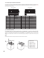
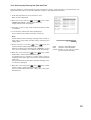
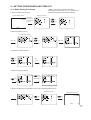
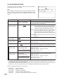
10.2.1. Terminal connection
The terminal connector is unlocked by pressing down on its release button. To connect the cable, press down
on the release button first, insert the cable, then push the release button up again to lock the cable in place.
However, for solid cables with diameters from 0.8 mm(AWG20) to 1.2 mm(AWG16), there is no need to press
down on the release button. Cable can be connected simply by inserting it in place until it will not go any
further.
Note
Ensure that the cable is securely locked into the terminal after connection.
2
Insert a cable.
1 Press down the
Release button.
Applicable cable
• Solid conductor
AWG26 (ø 0.4 mm) AWG16 (ø 1.2 mm)
3 Push the
release button up.
24
• Stranded conductor
AWG24 (0.2 mm2) AWG20 (0.75 mm2)
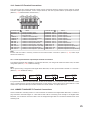
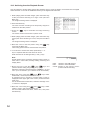
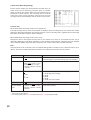
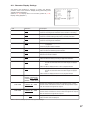
10.3. Control I/O Terminal Connections
The control input and output terminals include: priority recording terminal, camera control terminal, remote
controller input/output terminals, control output terminal, and time synchronization input/output terminals.
(Refer to p. 14; Nomenclature and Functions.)
PRIORITY
NC
IN G
1
A
G
2
CAMERA
+ G CONTROL OUT
G 3
G
RM IN-B
+ G 4
G
RM OUT-B
+ G TIME SYNC
IN G OUT G
B
Terminal name A
PRIORITY IN
PRIORITY G
NC
CAMERA +
CAMERA G
CAMERA RM IN-B +
RM IN-B G
RM IN-B RM OUT-B +
RM OUT-B G
RM OUT-B -
Name
Priority Recording Input
Priority Recording Ground
Not connected
Camera Control (RS-485) +
Camera Control (RS-485) Ground
Camera Control (RS-485) Remote Control Input B + (RS-485)
Remote Control Input B Ground
Remote Control Input B - (RS-485)
Remote Control Output B + (RS-485)
Remote Control Output B Ground
Remote Control Output B - (RS-485)
Terminal name B
CONTROL OUT 1
CONTROL OUT G
CONTROL OUT 2
CONTROL OUT G
CONTROL OUT 3
CONTROL OUT G
CONTROL OUT 4
CONTROL OUT G
TIME SYNC IN
TIME SYNC G
TIME SYNC OUT
TIME SYNC G
Name
Control Output 1
Control Output Ground
Control Output 2
Control Output Ground
Control Output 3
Control Output Ground
Control Output 4
Control Output Ground
Date/Time Adjustment Input
Date/Time Adjustment Input Ground
Date/Time Adjustment Output
Date/Time Adjustment Output Ground
Note
Ensure that the cable is securely locked into the terminal after connection. (Refer to p. 24; Alarm input
terminal connections.)
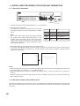
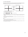
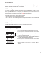
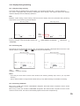
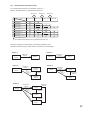
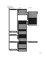
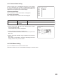
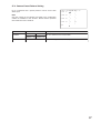
10.3.1. Time synchronization input/output terminal connections
Two different methods are available to synchronize the time, one using both master and slave units, the other
using NTP. (Refer to p. 100; Date/time setting.)
Note
When synchronizing a single-channel Digital Video Recorder, set the synchronization interval to “5 seconds.”
(Refer to p. 100; Date/time setting.)
Input Output
Master
Input Output
Slave 1
Input Output
Slave 2
Input Output
Slave 7
To synchronize the times of slave units with the time of the master unit, connect the slave units to the master
unit in a series via their input and output terminals. In other words, connect the input of slave number 1 to the
master unit’s output and the input of slave number 2 to slave number 1’s output, and so on.
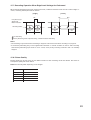
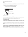
10.4. 10BASE-T/100BASE-TX Terminal Connections
Use this terminal to remotely monitor or control cameras connected to the Digital Video Recorder, or search or
play back their recorded images on a PC web browser. When connecting a PC directly to the Digital Video
Recorder, use a network crossover cable. Use the straight-through cable for connection between them via a
switching hub.
25
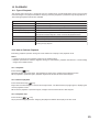
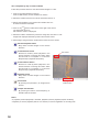
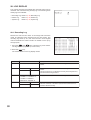
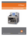
11. DIGITAL VIDEO RECORDER ACTIVATION AND TERMINATION
11.1. Recorder's Activation
DVD
ARCHIVE
KEY LOCK
1
9
2
10
3
11
4
12
5
13
6
14
7
15
PRIORITY
REC
8
16
BUZZER STOP/
ALARM RESET
MONITOR 1
ZOOM
SEARCH
MENU/
ENTER
MULTI
SCREEN
SEQUENCE
REC
FAILURE
HD FULL
MONITOR 2
DIGITAL VIDEO RECORDER C-DR161
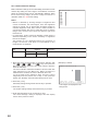
Power key
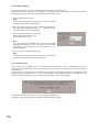
1. Connect each component correctly. (Refer to p. 20; Connections.)
2. Insert the power supply plug.
The Recorder is placed in standby mode. The power
key flashes at about 5-second intervals while in standby
mode.
Power key LED indicator
Distinguishes
Mode
Main power OFF
Flashes (5sec) Standby mode
Note
Do not pull out the power supply plug while the Power
key is light green. Ensure that the Recorder is in the
standby mode when pulling out the power supply plug.
Logged data could be damaged or lost if the power
supply plug is pulled out during initialization (while
accessing the hard disk).
During a system check
Flashes (1sec) (during activation)
Lights
Power ON (during operation)
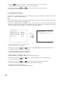
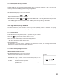
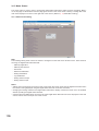
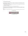
3. Press the Power key while the Recorder is in standby mode.
The screen automatically changes as shown below. The Power key flashes green during a system check.
The Power key changes from flashing to steady ON after system check completion, allowing camera
images to be displayed.
V e r
.
S Y S T EM
CHECK
P L EAS E
I N
PROGRE S S .
WA I T .
Notes
• When the Recorder is used for the first time, the date and time could not be correctly displayed. Perform the
clock setting before use. (Refer to p. 100; Date/time setting.)
• When the Digital Video Recorder is switched to standby mode, it cannot be switched on for about 10
seconds.
• Priority recording and auto-recording cannot be made in standby mode. Be sure to press the Power key
when making recording.
11.2. Recorder's Power Off and Disconnect
Hold down the Power key for 2 seconds or more. All operations stop, placing the Recorder in standby mode.
When moving the Recorder, be sure to place it in standby mode, then remove the power supply plug from the
wall outlet.
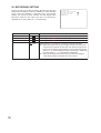
26
12. INITIAL SETTINGS
Be sure to perform the following settings before using the Digital Video Recorder. Failure to do so may lead to
incorrect operation of each function.
• DVR-ID setting (When cascade-connecting)
Note: When cascade-connecting the Digital Video Recorders, set the DVR-ID first. Otherwise, the Menu
screen is not displayed.
• Clock settings
• Hard disk initialization
• Auto-Recording settings
12.1. Setting the DVR-ID
When cascade-connecting the Digital Video Recorders, set different DVR-ID for all individual Digital Video
Recorders. DVR-ID are all factory-preset to "1." Follow the procedure below to set DVR number.
(Refer to p. 21; Digital Video Recorder's Expansion system.)
1. Press the Digital Video Recorder’s Power key while holding down the Sequence key in standby mode.
Camera Selection keys 1 – 8 flashes for about 1minute.
2. Press the desired DVR-ID to set.
The selected number flashes three times, then the number is programmed as DVR-ID.
Note: It is impossible to operate the Digital Video Recorder when the main power is set to OFF. Operate the
Digital Video Recorder after placing it in standby mode.
12.2. Clock Settings
Perform clock settings of the Digital Video Recorder. Adjust the date and time in Clock Settings on the menu
screen. (Refer to p. 100; Date/time setting.)
Notes
• If the clock setting is not performed, video recordings are not made according to the schedule set in the
auto-recording setting.
• In some cases, changing the current time may make it impossible to play back the recorded images
correctly when duplicated time data exists in the recording data.
MA I N
MENU
REC S E T T I
D I S P L AY S
N E T WO R K S
MA I L
S E T T
S Y S T EM S E
LOG D I S P L
DA T E / T I ME
MA I N T ENAN
I MAGE
N
E
E
I
T
A
G
T T
T T
NG
T I
Y
S E
CE
DA T E / T I ME
S E T T I NG
DA T E / T I ME
S E T T I NG
J AN /
I NG
I NG
NG
Menu key
T T I NG
ARCH I V I NG
D
D
D
D
A
A
A
A
S
T
T
T
Y
T
E
E
E
L
A
END
/
/
/
I
R
T
T
T
G
T
I ME A
I ME A
I ME A
H T
S E
DA T E
A
DA T E / T
O
1 / 0 5
0 0 : 0 0 : 0 0
D J US T OP ERA T E
D J US T
T I ME
D J US T OU T PU T
T T I NG
/ T I ME
PR
1 S T
WE E K S U
I ME
C T
L A S T WE E K S U
S
0
1
O
L AV E
0 : 0 0
S EC
N
N
0 2 : 0 0
N
2 2 : 0 0
1. Hold down the Menu key for 2 seconds or more.
The main menu screen is displayed.
2. Move the cursor with the [
] and [
key.
The clock setting screen is displayed.
] keys to select "DATE/TIME SETTING," then press the Menu
3. Move the cursor with the [
] and [
] keys and perform clock settings using the [+] and [-] keys.
Set year, month, date, hour, minute, and second.
27
4. Press the [
] key while the cursor is set to the leftmost selection item on the screen.
The indication will appear to ask whether or not to save the setting.
5. Move the cursor with the [
] and [
] keys, select "YES," then press the Menu key.
The display reverts to the main menu screen.
12.3. Hard Disk Initialization
Set disk mode (normal mode and mirror mode) used for recording to the hard disk to initialize the hard disk.
(Refer to p. 101; Equipment Maintenance.)
Notes
• Since initializing the hard disk erases all recorded images, be sure to copy the necessary data to DVDR/RW disks or USB memory before initialization.
• Disk mode is factory-preset to "NORMAL." Leave the disk mode as it is when using the Digital Video
Recorder in normal mode. However, it is recommended that the hard disk be initialized since recording
starts automatically when the Digital Video Recorder's power is switched on.
MA I N T ENANCE
HD
I
S E T T
LOG
E X PO
I MPO
USB
USB
D I SK
D I SK
N
I
I
R
R
K
K
I
N
N
T
T
E
E
T I A L
G
I N
I T I A
S E T
S E T
Y RE
Y DA
I
I
L
T
T
G
T
ARRAY 1
ARRAY 2
HD
Z
T
I
I
I
I
A
E
I
Z
N
N
S
A L I Z E
E
G DA T A
G DA T A
T RA T I ON
ERASURE
E
E
E
E
E
E
X
X
X
X
X
X
E
E
E
E
E
E
C
C
C
C
C
C
U
U
U
U
U
U
T
T
T
T
T
T
I N I T I A L I Z E
D I S K MOD E
E X ECU T E
E
E
E
E
E
E
Menu key
HDD – A
HDD – B
NORMA L
E X ECU T E
MAS T ER
MAS T ER
1 6 0 GB
1 6 0 GB
S L AV E
S L AV E
- - - - DVD
UNUS ED
UNUS ED
1. Hold down the Menu key for 2 seconds or more.
The main menu screen is displayed.
2. Move the cursor with the [
] and [
] keys to select "MAINTENANCE," then press the Menu key.
The Equipment Maintenance screen is displayed.
3. Select "HD INITIALIZE," then press the Menu key.
The Hard Disk Initialization screen is displayed.
4. Select the disk mode using the [+] and [-] keys.
Select "NORMAL," or "MIRROR." (Refer to p. 38; Before Recording.)
5. Move the cursor with the [
] and [
"Yes" and "Cancel" are displayed.
] keys to select "EXECUTE," then press the Menu key.
6. Move the cursor with the [
] and [
] keys to select "YES," then press the Menu key.
Confirmation message is displayed after executing the hard disk initialization.
7. Select “OK,” then press the Menu key.
The display returns to the hard disk initialization screen.
28
12.4. Auto-Recording Settings
Recordings are normally performed according to the preprogrammed schedule. Therefore, perform schedule
or group settings when making auto-recording. (Refer to p. 79; Auto recording setting.)
12.4.1. Schedule setting
Set the schedule (Day, Start time, and End time) for each group to operate.
Menu key
Menu key
1. Hold down the Menu key for 2 seconds or more.
The main menu screen is displayed.
2. Select "REC SETTING," then press the Menu key. The Recording setting screen is displayed.
3. Move the cursor with the [
] and [
] keys to select "AUTO REC SETTING," then press the Menu
key.
The Auto-recording setting screen is displayed.
4. Select "SCHEDULE," then press the Menu key.
5. Move the cursor with the [
], [
], [
], and [
] keys and perform schedule setting using the [+]
and [-] keys.
Set a day of the week, Start time, End time and manner of operation (group setting). (Refer to p. 79; Auto
recording setting.)
6. Press the [
] key while the cursor is set to the leftmost selection item on the screen.
The indication will appear to ask whether or not to save the setting.
7. Move the cursor with the [
] and [
] keys to select Yes, then press the Menu key.
The display reverts to the auto-recording setting screen.
29
12.4.2. Setting the group
Perform individual settings such as Normal recording and Alarm Event recording for Group A - F.
AU TO
SCH
GRO
GRO
GRO
GRO
GRO
GRO
S P E
MO T
AUD
E
U
U
U
U
U
U
C
I
I
REC
D
P
P
P
P
P
P
I
O
O
U
–
–
–
–
–
–
A
N
S E T T I NG
GROUP – A
L E
A S E T T I NG
B S E T T I NG
C S E T T I NG
D S E T T I NG
E S E T T I NG
F
S E T T I NG
L DAY S E T T I NG
S E T T I NG
Menu key
NO
A L
A L
A L
PO
MO
PO
RMA L
ARM E
ARM E
ARM
I
S T A L
T I ON
S T MO
S E T T I NG
R
V
V
N
A
D
T
EC S E T T I NG
EN T REC S E T T I NG
E N T R E C MOD E
P U T MOD E
RM T I ME
E T E C T MOD E
I ON T I ME
S
E
9
L
E
D
9
E
Q
G
9
V
1
U
E
S
E
S
ENCE
EC
L
EC
ON
1. Choose “Group A-F” from the Auto-recording Settings and press the Menu key.
The Group setting screen is displayed.
2. Move the cursor with the [
], [
], [
], and [
] keys and perform Group setting using the [+]
and [-] keys.
For a detailed information, refer to “Group A-F settings.“ (Refer to p. 80; Setting of groups A – F.)
3. Press the [
] key while the cursor is set to the leftmost selection item on the screen.
The indication will appear to ask whether or not to save the setting.
4. Move the cursor with the [
] and [
] keys to select "YES," then press the Menu key.
The display reverts to the auto-recording setting screen.
12.4.3. Other settings
In Auto-Recording Settings, “special day,” “motion detection,” and “audio (ON/OFF)” settings can be
performed in addition to both schedule and group settings. (Refer to p. 79; Auto-recording setting.)
30
13. MONITOR DISPLAY
Functions that can be displayed differ between Monitor Outputs 1 and 2.
Playback mode
Live mode
Function
Full
4 Seg
9 Seg
16 Seg* Sequence
Full
4 Seg
9 Seg
16 Seg*
Electronic
Zoom
Cascade
output
Monitor output 1
Monitor output 2
Function
Digital Recorder
menu
Search
menu
Display position
setting screen
Triplex setting
screen
Archive
menu
Monitor output 1
Monitor output 2
* Only the C-DR161 Series (16-channel versions) can display.
13.1. Monitor Switch
Operations of Monitor 1 and Monitor 2 outputs switch with each depression of the Monitor key.
Monitor 1 output is enabled when the Monitor key is unlit, and Monitor 2 output is enabled when the Monitor
key is lit.
13.2. About Live and Playback Modes
Display can be switched between live and playback modes
Pressing the Play key when in live mode switches the screen to playback mode, while pressing the Stop key
when in playback mode switches the screen to live mode. The multi-segment split screen display is
maintained even if the mode is switched.
Live mode: Displays current camera images. The camera number is displayed following the “L” indication.
Playback mode: Displays recorded camera images. The camera number is displayed following the “PB”
indication.
31
13.3. Display when in live mode
The following indications appear when in live mode.
1
SA T
DVR NAME
A L ARM
2
M
4
5 6
(1) Camera number
“L” represents the live pictures. The number
indicates the input number of the camera
images.
(2) DVR name
(Refer to p. 89; DVR Name setting.)
(3) Recording status
Indicates that normal recording is in
progress.
ALARM: Indicates that alarm recording is in
progress. The number is an alarm
input terminal number.
MOTION:Indicates that motion detected
recording is in progress. The number
is a camera number that detects
motions.
PRIOR: Indicates that priority recording is in
progress.
(4) Audio recording ON/OFF
:
AB
NAME
7
8
9
10
(7) Camera name
(Refer to p. 89; Camera name setting.)
(8) Available hard disk time
Displayed when in Write Protect mode.
(9) Fan failure
The “ ” indication lights when the fan fails.
This indication cannot be set to “Hide” in screen
display settings.
(10) Hard disk in use
Indicates the hard disk currently making
recording.
A, B *1: Built-in hard disk
C, D: Hard disk expansion unit 1
E, F:
Hard disk expansion unit 2
*1 “B” is not displayed for single-hard disk
models (versions with model number suffix -8,
1, D08 or D1).
One of “A”-“F” is displayed during normal
mode. Two characters from “A”- ”F” are
displayed during mirror mode.
Audio recording enabled.
(Refer to p. 77; Priority recording setting.)
(Refer to p. 79; Auto recording setting.)
(Refer to p. 85; Pre-recording settings.)
(11) Current date and time
(Refer to p. 100; Date/Time setting.)
This position can be moved by settings.
[No indication]: Audio recording disabled.
Notes
• Either (1) or (7) can be displayed.
• All indications but (9) can be set to Display/Hide by
menu.
(5) Overwrite settings
(Refer to p. 76; Recording setting.)
: Write Protect
: Overwrite
(6) Disk mode
(Refer to p. 102; Hard disk drive initialization.)
M:
Mirror mode
[No Indication]: Normal mode
32
J AN / 0 1 / 0 5
0 : 0 0 : 0 0
1 D 1 2 H
CAM
3
:
11
L 1
13.4. Display during Playback
The following indications appear while the playback screen is displayed:
1
8
PB 1
SA T
DVR 1
P L AY
2
J AN / 0 1 / 0 5
0 : 0 0 : 0 0
2
A
CAM1
3
4
5
7
6
(1) Camera number being played back
“PB1” represents playback image. The number
represents the input number of the camera
images.
(5) Recording state
: Priority recording or Auto recording in
progress
[No indication]: Recording stop state
(2) DVR name
(Refer to p. 89; DVR name setting.)
(6) Camera name
(Refer to p. 89; Camera name setting.)
(3) Playback mode
(7) Hard disk being played back
A: Plays back the first built-in hard disk
B: Plays back the second built-in hard disk
(versions with a model number suffix -3, -6,
D3, or D6 only).
C -: Plays back the hard disk expansion unit’s
hard disk.
PLAY:
Playback in progress.
PLAY:
Fast forward quick playback in
progress.
REV:
Reverse playback in progress.
REV:
Fast reverse playback in progress.
(8) Recording date and time
This display position can be changed by settings.
PAUSE: Playback temporarily stops.
(4) Fast forward/reverse playback speed
X2, X4, X8: Quickly plays back forward or in
reverse at the indicated speed.
1M, 10M: Quickly plays back forward or in
reverse skipping images in 1-minute/10-minute
segments.
Notes
• Either (1) or (6) can be displayed.
• All indications but (7) can be set to Display/Hide by
menu.
13.5. Full-Screen Display
Pressing the Camera Selector key while in live or playback mode displays the selected camera output on the
full screen.
L 1
L 2
L 1
L 3
SA T
J AN / 0 1 / 0 5
0 : 0 0 : 0 0
L 4
L 5
L 6
L 7
L 8
L 9
SA T
J AN / 0 1 / 0 5
0 : 0 0 : 0 0
Press the Camera
Selector key No. 3.
AB
AB
33
13.6. Multi-Segment Split-Screen Display
When the live or playback screen is displayed, the multi-segment split-screen display changes as shown
below each time the Multi-Screen key is pressed. Multi-Screen key lights continuously during multi-Segment
Split-Screen display.
9-channel DVR :
4 Seg A
4 Seg B
9 Seg
4 Seg C
16-channel DVR:
4 Seg A
4 Seg B
16 Seg
4 Seg C
9 Seg B
4 Seg D
9 Seg A
(Example) Screen display in live mode (9-channel DVR)
4-segment split B
4-segment split A
L 1
L 2
L 5
SA T
L 6
J AN / 0 1 / 0 5
0 : 0 0 : 0 0
SA T
J AN / 0 1 / 0 5
0 : 0 0 : 0 0
Press the
Multi-Screen key.
L 3
L 4
L 7
L 8
AB
AB
Press the
Multi-Screen key.
Press the
Multi-Screen key.
9-segment split
L 1
L 4
L 2
L 5
4-segment split C
L 9
L 3
SA T
J AN / 0 1 / 0 5
0 : 0 0 : 0 0
SA T
L 8
L 6
L 3
L 9
AB
34
J AN / 0 1 / 0 5
0 : 0 0 : 0 0
Press the
Multi-Screen key.
L 2
L 7
L 1
AB
13.7. Sequence Display
Camera live images are displayed in sequential order when the Sequence key is pressed while in live mode.
Viewing intervals and cameras to be displayed can be set on the menu screen. Sequence key lights
continuously during Sequence display. (Refer to p. 88; Sequence Setting.)
(Setting Example)
Step 1 : Camera 1
Step 2 : Camera 2
Step 3 : Camera 3
Step 4 : 4-split A
Step 1
3 seconds
3 seconds
3 seconds
3 seconds
Step 2
L 1
L 2
SA T
J AN / 0 1 / 0 5
0 : 0 0 : 0 0
SA T
3 seconds elaps
AB
Note
That when the screen is switched, the
picture may be distorted momentarily.
J AN / 0 1 / 0 5
0 : 0 0 : 0 0
AB
3 seconds elaps
3 seconds elaps
Step 4
L 1
Step 3
L 3
L 2
SA T
SA T
J AN / 0 1 / 0 5
0 : 0 0 : 0 0
J AN / 0 1 / 0 5
0 : 0 0 : 0 0
3 seconds elaps
L 3
L 4
AB
AB
13.8. Zoom Display
Live or recorded full-screen images can be viewed in 2 x zoom display. Zoom key lights continuously while the
Zoom selection screen or Zoom screen is displayed.
Live or play back screen
Zoom selection screen
Zoom key
Zoom key
Zoom screen
Menu key
Menu key
Zoom key
1. Press the zoom key
The zoom selection screen is displayed. The pointer is displayed on the screen.
2. Move the central point of the subject to be zoomed using the [
], [
], [
], and [
] keys, then
press the Menu key.
The subject can be zoomed with the designated point at the center. Zoomed areas can be moved using the
[
], [
], [
], and [
] keys even while zoomed.
3. Press the Menu key when the zoom screen is displayed.
The display reverts to the zoom selection screen. Pressing the Zoom key again when the zoom screen is
displayed resets the zoom display.
Note
When channels are changed, multi-segment split-screen display is selected, or a search function is operated
during zoom display, the zoom mode is reset.
35
14. OTHER FUNCTIONS
14.1. Triplex Display
Holding down the Multi-Screen key for 2 seconds or more during playback, including fast forwarding,
rewinding, and pause, on the multi-segment split screen switches the display to Triplex setting screen. The
Triplex setting permits live camera images to be viewed among recorded images displayed on the multisegment split screen. The Triplex setting is maintained even when the power is switched OFF.
During playback
PB 1
Triplex setting screen
Hold down the Multi
-Screen key for
2 seconds or more
PB 2
PB 3
PB 4
PB 1
T R I P L E X
PB 3
L 5
S E T T I NG
PB 4
Hold down the
Menu key for
2 seconds or more
1. Hold down the Multi-Screen key for 2 seconds or more.
The triplex setting screen is displayed.
2. Press the [
], [
], [
], and [
] keys to move the cursor.
3. Press the Camera selector key.
When the Camera selector key is pressed, the live screen corresponding to the selected camera output is
displayed in the position indicated by the cursor. A dark screen is displayed if the selected camera is not
connected.
4. To revert the set live images to the playback images, press the Sequence key.
Pressing the Sequence key resets the selected position's live display and switches it to the playback image.
5. Hold down the Menu key for 2 seconds or more.
The triplex setting screen is terminated.
Notes
• It is impossible to set all screens to the live display.
• Two or more live image screens cannot be set for the same camera.
36
14.2. Position Setting Display
Holding down the Multi-Screen key for 2 seconds or more when the live multi-segment split screen is
displayed displays the position setting screen. Camera images can be displayed at arbitrary positions on the
multi-segment split screen. The position setting for each multi-segment split screen is saved.
During Live images are displayed
L 1
L 3
Position setting screen
Hold down the Multi
-Screen key for
2 seconds or more
L 2
L 4
L 1
POS I T I ON
L 3
L 2
S E T T I NG
L 4
Hold down the
Menu key for
2 seconds or more
1. Hold down the Multi-Screen key for 2 seconds or more.
The position setting screen is displayed.
2. Press the [
], [
], [
], and [
] keys to move the cursor.
3. Press the Camera selector key.
When the Camera selector key is pressed, the live screen corresponding to the selected camera output is
displayed in the position indicated by the cursor. A dark screen is displayed if the selected camera is not
connected.
4. Hold down the Menu key for 2 seconds or more.
When the Menu key is pressed, the setting screen is terminated in the current state, returning the display to
the live screen.
Notes
• If live picture of selected camera number is already displayed on the position setting screen, it is switched
with the live screen of the camera during selection.
• Position of camera images through Monitor 2 cannot be changed.
• When an alarm event occurs during display position setting, the alarm-activated camera image is recorded
but not displayed on the full screen.
37
15. RECORDING
15.1. Before Recording
Auto-recordings are normally performed according to the preprogrammed schedule. Operations to start
recording such as pressing the key are not required. You can also make recording by pressing the Priority
Recording key outside the scheduled time period. Perform disk mode and overwrite settings before recording.
15.1.1. Disk mode
Normal and mirror modes are available to this mode. For models with a single hard disk (versions with a
model number suffix -08, -1, D08 or D1), Mirror settings are available only when the hard disk expansion unit
is connected. (Refer to p. 101; Equipment maintenance.)
Notes
• When the disk mode is changed, the hard disk is initialized, causing the recorded images to be erased. Be
sure to determine the disk mode before use.
• Unless the disk mode setting is performed, mirror recording cannot be performed as the hard disk is factorypreset to normal mode.
Normal mode:
Mirror mode:
When the first hard disk finishes recording, the second hard disk automatically begins to
record. When the settings (recording rate and picture quality) of both normal and mirror
modes are set to be identical, the recording time for normal mode is about twice that of
mirror mode. The total recording rate is 120 IPS maximum.
The same image is simultaneously recorded on both hard disks. Even if one of the two
hard disks fails, the other hard disk continues to record, allowing all recorded images to be
played back. The total recording rate is 60 IPS maximum. Set the disk mode to Mirror
when performing mirroring by the two built-in hard disks or when performing mirroring by
the built-in hard disk and the hard disk expansion unit.
15.1.2. Recording order to hard disks
Recordings to the built-in hard disks are performed in the following order.
Normal mode
Mirror mode
One hard disk
Two hard disks
One hard disk
Two hard disks
HDD A
HDD A
HDD A
HDD A
HDD B
HDD B
Note
For the recording operation when the expansion unit is connected, refer to the instruction manual enclosed
with the expansion unit.
38
15.1.3. Disk recording mode
Overwriting of hard disk recordings can be set to Overwrite or Write Protect. (Refer to p. 76; Recording
Settings.)
Overwrite:
When all hard disks become full, previous recorded older data is automatically deleted and
replaced with newer data.
Write Protect: When all hard disks become full, recording is stopped. To begin recording again, initialize the
hard disk and reactivate the Digital Video Recorder, or set the disk-recording mode to
"Overwrite."
15.2. Recording Mode
The following recording modes are available to the Digital Video Recorder. Priorities are 1, 2 and 3 in that
order.
Recording mode
Priority Recording 1
Auto-recording
(operation according
to the schedule)
Alarm event recording 2
Alarm-input recording
Motion-detected recording
Normal recording 3
Pre-Alarm recording
(operates only in recording stop mode)
15.3. Priority Recording
Priority recording is given higher priority over Auto-recording. Use this recording mode to check recording
details when, for example, a suspicious person intrudes or when making recording outside the scheduled time
period. In the Priority Recording settings, the following settings can be made for individual cameras: recording
ON/OFF, recording rate, picture quality and audio ON/OFF. (Refer to p. 77; Priority Recording setting.)
15.3.1. How to perform priority recording
1. Press the Priority Recording key to start the priority recording. To stop a buzzer sound, press the Buzzer
Stop key.
2. Hold down the Priority Recording key for 2 seconds or more to terminate the priority recording.
Notes
Priority recording can be started by any of the following ways.
• Input the signal to the Priority recording input terminal on the rear panel.
• Press the Remote Controller's Priority Recording key.
39
15.4. Auto Recording (Alarm Event Recording and Normal Recording)
With auto-recording, recordings are made according to a preset schedule, which can include up to twelve
different programs. If one or more programs have duplicate execution times, the program with a largest
number takes precedence. Settable items for each program include: Day of the Week; Start/End Times; and
Operation. Up to six settings groups, named A through F, can be made for “Operation,” and recording settings
for Normal and Alarm recording can also be registered. Further, up to sixty “special day” operational settings
can also be made, with operation controlled by different programs, motion detection areas for individual
cameras, and audio recording during auto- recording. (Refer to p. 79; Auto-Recording Settings.)
Notes
• If the Alarm display interval is set to "0" second, no full-screen display is performed and the current display
status is maintained.
• If an alarm event occurs outside the scheduled time period, Alarm Event recording is not performed.
15.4.1. Alarm event recording
Alarm Event recording includes both “Alarm Input” and “Motion Detection” recording. For Alarm Event
recording, settable items for each individual camera include: Recording ON/OFF; Recording Rate; and Picture
Quality. It is also possible to set, for each recording mode, the type of events that will cause recording to
begin. (Refer to p. 82; Alarm Event Recording Setting.)
For Alarm Event recording mode, it is possible to set the type of recording operation to be performed when
multiple events have occurred simultaneously. Setting the mode to “Sequence” allows two or more events to
be set for individual cameras. For Alarm Input recording time, set both alarm input mode and post alarm time
intervals. For Motion Detection, set both motion detection mode and post-motion alarm time. (Refer to p. 80;
Setting of groups A-F.)
When an alarm event occurs, the corresponding camera’s image is switched to full-screen display until the
preset alarm time interval has elapsed, after which the display reverts to the original screen display. (Refer to
p. 86; Screen Display Setting.)
Alarm input recording:
Alarm Input recording begins when signals are received at the alarm input
terminal on the rear panel. Use Event settings to link cameras that are to have
their images recorded and alarm input terminal. If “Sequence” is selected, up to
four alarm input terminals can be set optionally per camera. If “Last” is
selected, the “Alarm ON/OFF” can be set only for the alarm input terminal with
a number corresponding to that of the camera.
Motion detected recording: Motion Detection recording begins when motion is detected in a camera image.
Use Motion Settings to set the motion detection area, sensitivity, and activation.
Use Event settings to link cameras that are to have their images recorded and
cameras that are to use motion detection. If “Sequence” is selected as the
alarm event recording mode, then up to four alarm input terminals can be set
optionally per camera. If “Last” is selected, the “Alarm ON/OFF” can be set only
for the alarm input terminal with a number corresponding to that of the camera.
40
15.4.2. Normal recording
This function automatically records camera images set by schedule. For Normal recording, settable items for
each individual camera include: Recording ON/OFF; Recording Rate; and Picture Quality. (Refer to p. 81;
Normal Recording setting.) Recordings can be made on scheduled patterns like "day and night," and
"weekdays and holidays” by combining two or more programs.
15.5. Pre-Recording
This function records images immediately before Priority recording or Alarm Event recording is initiated.
Setting the Pre-Recording interval to 1 second or more allows Pre-Recording to be performed. In PreRecording, the recording rate and picture quality cannot be individually set for each camera. Instead,
recording rate, picture quality, and audio ON/OFF settings are common to all connected cameras. The
maximum recording rate per camera is 4 IPS. (Refer to p. 85; Pre-Recording setting.)
Pre-Recording can be performed under the following conditions.
• When Priority recording begins while recording is stopped.
• When an alarm event occurs and alarm even recording begins while a schedule in which Normal Recording
is not available but Alarm Event Recording is available is in operation.
Note: Pre-Recording cannot be performed during Normal Recording.
15.6. Recording State
The Digital Video Recorder permits recordings to be set to best meet user requirements.
Recording within a scheduled time period
[ Auto recording (Normal recording) ]
Recording is performed as shown in the following figure when set to always automatically record (Normal
recording):
Priority recording
1
Priority recording
start
2
End
5
Normal recording
3
Alarm event
start
End
Start
4
End
Alarm event recording
Alarm input recording
Motion-detected recording
6
(1) Priority recording is initiated if Priority recording's event occurs.
(2) When the Priority recording ends, recording reverts to Normal
recording mode.
(3) Alarm Event recording is initiated if the alarm input terminal
receives a signal or if motion movement is detected.
(4) When the preset Alarm Event recording interval elapses, recording
reverts to Normal recording mode.
(5) Priority recording is initiated if a Priority signal is received or if
manually started during Alarm Event recording.
(6) When the Priority recording ends, recording reverts to Normal
recording.
Notes
• Perform Normal recording settings in auto recording settings.
• Normal recordings are factory-preset to “recordings ON" for all
cameras.
41
Recording within a scheduled time period
[ Recording only when Priority recording is initiated or alarm event occurs ]
To stop recording within the scheduled time period, set all cameras to “Recording OFF” in normal recording
settings. To perform recording only when Priority recording or Alarm Event recording is initiated, recording is
performed as shown in the following figure.
Priority recording
Priority recording
start
Pre-Alarm
recording
1
Start
5
2
End
Pre-Alarm
recording start
Recording stop
Pre-Alarm
recording start
Pre-Alarm
recording
3
4
End
Alarm event
start
Alarm event recording
Alarm input recording
Motion-detected recording
End
6
(1) If the Priority recording's event occurs, Pre-Recording is first
made, then Priority recording begins.
(2) When the Priority recording ends, recording reverts to recording
stop mode.
(3) If Alarm Event recording is initiated, Pre-Recording is first made,
then Alarm Event recording begins.
(4) When the preset Alarm Event recording interval elapses, recording
reverts to recording stop mode.
(5) Priority recording is initiated if a Priority signal is received or if
manually started during Alarm Event recording.
(6) When the Priority recording ends, recording reverts to Normal
recording.
Notes
• Even if Priority recording or Alarm recording is initiated, it is made
following Pre-Recording.
• Pre-Recording is initiated when the Pre-Alarm interval is set to 1
second or more.
Recording outside scheduled time periods
[ Recording only when Priority recording is initiated ]
Recording is performed as follows outside the scheduled time period.
Priority recording
Priority recording
start
1
Pre-Alarm
recording
2
(1) When the Priority recording's event occurs, Pre-Recording is first made,
then Priority recording begins.
(2) When the preset Priority recording interval elapses, recording reverts to
recording stop mode.
End
Pre-Alarm
recording start
Recording stop
42
Notes
• Normal recording and Alarm event recording cannot be performed.
• If Priority recording is initiated, Pre-Recording is first made, then Priority
recording begins.
• Pre-Recording is initiated when the Pre-Alarm interval is set to 1 second
or more.
15.7. Recording Operation When Edge/Level Settings Are Performed
When Priority Recording Input mode, Alarm Input mode, or Motion Detection mode are set to either "Edge" or
"Level," recording will be performed as follows.
[ Edge ]
[ Level ]
ON
ON
OFF
Priority Recording Input
Alarm Input
Motion Detection
1
2
1
Pre-Recording
Time
Post Recording
Time
Pre-Recording
Time
Recording Status
2
Post Recording
Time
1 Pre-Recording
2 Priority Recording, Alarm Input Recording, or Motion Detection Recording
Notes
• Pre-recording only functions when recording is stopped. It cannot be used when recording is in progress.
• If the Priority Recording Key on the Digital Video Recorder or remote controller is used to start recording
when Priority Recording Input mode is set to "Level," then priority recording continues until it is manually
stopped.
15.8. Picture Quality
Picture quality can be set at any of five different levels for each recording mode and camera. File sizes for
each picture quality are shown below.
Note: File size may differ depending on the images.
Picture Quality
File Size
1 (Highest)
64 KB
2
40 KB
3
32 KB
4
24 KB
5 (Lowest)
16 KB
43
15.9. Recording Rate
The recording rate indicates the number of images to be recorded per second and is expressed by the unit
IPS (Image Per Second). In the Digital Video Recorder, the total recording rate is the sum of each camera’s
recording rate and recordings can be made for up to 120 IPS in normal mode and for up to 60 IPS in mirror
recording mode. The maximum recording rate that can be set per camera is 60 IPS.
The recording rate to be set on the menu screen is displayed, rounded up. The following table shows the
relationship of menu screen display vs. actual recording rate.
Menu screen display
60
30
15
8
4
2
1
Actual recording rate
60.000000
30.000000
15.000000
7.500000
3.750000
1.875000
0.937500
Menu screen display
1/2
1/3
1/5
1/10
1/20
1/30
1/60
Actual recording rate
0.468750
0.312500
0.187500
0.093750
0.049342
0.033482
0.016741
The total recording rate is calculated by the actual recording rate in the above table. If, for example, each of
16 cameras is set to a menu screen display value of 8 IPS, the total recording rate is 120 IPS since the actual
per-unit recording rate is 7.5 IPS.
Also, if a recording rate of 1/2 IPS or less (1/2 -1/60) is designated, the total rate is calculated using the rate
of 0.937500.
15.10. Recording time
Recording time varies depending on the settings described below.
For recording time, refer to p. 116, "Recording timetable" as a guide.
• HDD Capacity (80 GB - 600 GB)
• Recording rate (60 - 1/60)
• Picture quality (1 - 5)
• Audio (ON/OFF)
15.11. Available Disk Time and Operation
When disk recording mode is set to “Overwrite,” the available time indication is not displayed and the disk
space indicator does not light. In “Write Protect” mode, when the remaining time is shorter than the preset
remaining warning time, the disk space indicator lights and recording is stopped.
44
16. PLAYBACK
16.1. Type of Playback
The Digital Video Recorder is equipped with the simultaneous recording/playback function that permits
recorded images to be played back without stopping recording. Playback is performed only through Monitor 1.
The following playback methods are available.
Type
Description
Playback
Plays back recorded images.
Reverse playback
Plays back recorded images in reverse chronological order.
Earliest image playback
Plays back from the earliest recorded image.
Latest image reverse playback
Plays back in reverse from the most recent recorded image.
Fast forward/reverse playback
Plays back recorded images forward or in reverse at 2x, 4x or 8x speed. Playback
speed can be increased using the 1-minute/ 10-minute skip playback function.
Pause
Temporarily stops playback and displays still pictures.
Frame advance/reverse playback
Plays back images in pause on a frame by frame basis.
Instant event access playback
Moves to the event start time (Priority recording, Alarm Event recording and Normal
recording) to begin playback.
16.2. How to Perform Playback
Performing playback operation during live mode switches the display to the playback mode.
Notes
• If power is turned off, the playback starts from the earliest image.
• Playback performance could be degraded during live transmission, playback transmission or downloading
using the PC's Web browser.
16.2.1. Playback
Press the Play [
] key.
Recorded images are played back. The Playback key lights green, displaying the playback screen.
When playback is performed again, playback begins from the time at which it last stopped.
16.2.2. Reverse playback
Press the Reverse Play [
] key.
Plays back recorded images in reverse chronological order. The Reverse Play key lights green, displaying the
reverse playback screen.
When reverse playback is performed again, it begins from the time at which it last stopped.
16.2.3. Playback stop
Press the Stop [
] ( ) key.
Stops pictures being played back. Stopping the playback switches the display to the live mode.
45
16.2.4. Earliest image display
Press the Play [
] key while holding down the Playback Stop [
] (
Playback begins from the time at which the earliest image was recorded.
) key.
16.2.5. Latest image reverse playback
Press the Reverse Play [
] key while holding down the Playback Stop [
] (
Reverse playback begins from the time at which the latest image was recorded.
) key.
16.2.6. Fast forward/reverse playback
Press the Play [
] key (Reverse Play [
] key when in reverse playback mode) during playback.
Fast forward playback (fast reverse playback when in reverse playback mode) is initiated. Playback speed
cycles through 2X, 4X and 8X whenever the key is pressed. The speed can be increased using the 1-minute
or 10-minute time skip function.
Playback speed
Normal speed
2 times (X2)
10-minute time skip (X10 minute)
4 times (X4)
8 times (X8)
1-minute time skip (X 1 minute)
Notes
• The 1-minute/10-minute skip function may not operate correctly if recordings are made with the clock turned
back.
• Recorded images may not be played back at the indicated speed depending on the hard disk access time,
etc.
• For the pre-recorded recording data, it cannot playback skips forward in 1-minute/10-minute segments.
16.2.7. Pause
1. Press the Pause [
](
) key during forward or reverse playback.
Playback is temporarily stopped and the key lights green.
2. To perform playback or reverse playback again, press the Play [
] key or Reverse Play [
Pause mode is cancelled and forward or reverse playback begins again.
] key.
16.2.8. Frame advance/frame reverse playback
Press the Play [
] key or Reverse Play [
] key with the Pause [
] (
) key pressed, while
recording is temporarily stopped.
Frame advance or reverse playback is performed per screen whenever the key is pressed.
46
16.3. Event
Events that can start recording include Priority recording, Normal recording, Alarm input recording, and Motion
detection recording. Each event can be confirmed using the recording log. (Refer to p. 98; Recording Log.)
16.3.1. Instance event access
Recording moves to the event start time (Priority recording, Alarm Event recording or Normal recording) and
temporarily stops. Playback images can be moved from event to event and required images can be quickly
searched.
[Instant access to the next event]
Hold down the Play [
] key for 2 seconds or more while recording is temporarily stopped.
Recording advances to the beginning of the next event and temporarily stops.
Hold down the [
] key for 2 seconds or more while recording is temporarily stopped.
Instant Event Access
Event
Event
Event
Playback direction
[Instant access to the previous event]
Hold down the Reverse Play [
] key for 2 seconds or more while recording is temporarily stopped.
Recording advances to the beginning of the previous event and temporarily stops.
Hold down the [
] key for 2 seconds or more while recording is temporarily stopped.
Instant Event Access
Event
Event
Event
Playback direction
47
17. SEARCH
Pressing the Search key in the live mode or in the playback mode displays the search screen. Two search
methods are available: Date/time search by designating the specific time, and event search by designating the
event.
Note
It may take a relatively long time to search (During recording, Web playback distribution, Web download or
Expansion unit connection). It also takes time to search if a lot of event numbers exist.
Search
Menu item
Setting item
Date/Time search
Time
Event search
Camera
S EARCH
DA T E / T I ME S EARCH
E V EN T
S EARCH
Event
Start time
End time
17.1. Date/Time Search
Entering the date and time to perform a search displays all camera images recorded closest to the designated
time in freeze-frame on the 16-segment (or 9-segment) split screen display. If no recording is made on the
designated date and time, the date and time closest after the designated date and time is displayed. The
oldest and newest times for recorded data are displayed, so please enter dates and times occurring between
these.
1. Press the Search key.
The Search screen is displayed.
2. Select “DATE/TIME SEARCH,” press the Menu key.
Date/Time search screen is displayed.
3. Move the cursor with the [
] and [
] keys and perform
clock settings using the [+] and [-] keys. Set year, month,
date, hour, minute, and second.
4. Move the cursor to “EXECUTE” and press the Menu key.
Images recorded at the time closest to the designated time
are displayed.
48
DA T E / T I ME
S EARCH
DA T E / T I ME
S EARCH
F EB / 2 4 / 0 5
E X ECU T E
0 5 : 0 0 : 0 0
REC
REC
F EB / 2 4 / 0 5
F EB / 2 5 / 0 5
0 5 : 0 0 : 0 0
0 5 : 0 0 : 0 0
S T AR T
END
S EARCH
SCRE EN D I S P L AY
T I ME
F EB / 2 4 / 0 5
0 5 : 0 0 : 0 0
Item
Selection
Description
DATE / TIME
JAN / 01 / 00 00:00:00 DEC / 31 / 99 23:59:59
Designate the date and time to research.
SEARCH
EXECUTE
Search begins if “Execute” is selected.
REC START
Displays the time for the oldest video recording.
REC END
Displays the time for the newest video recording.
SEARCH SCREEN
DISPLAY TIME
Displays the time at which the search screen was displayed.
An error message is displayed at upper right of the screen if
images does not exist after the designated time.
Pressing the Menu key moves the cursor to the previous
position.
N O T H I N G
F O U N D
O K
Notes
• In some cases, changing the current time may make it impossible to search by time when duplicate time
data exists in the hard disk.
• When recording with overwrite permission, recorded images are overwritten three minutes after the time
search screen has been displayed, making it impossible to search or display data in the vicinity of the oldest
time. Refer to Search Screen Display Time.
17.2. Event Search
The event search begins under the designated conditions.
1. Press the Search key.
The search screen is displayed.
2. Select “EVENT SEARCH,” then press the Menu key.
Event search screen is displayed.
3. Move the cursor with the [
], [
], [
], and [
]
keys, and perform camera, event, start time and end time
settings using the [+] and [-] keys.
4. Move the cursor to “EXECUTE,” then press the Menu key.
Event search list is displayed.
5. Move the cursor using the [
] and [
] keys, select the
desired event from the event search list, and then press the
Menu key. The image at the event start time is displayed in
freeze-frame on the 16-segment (or 9-segment) split screen
display.
E V EN T
C
E
S
E
S
AME
V EN
T AR
ND
EAR
S EARCH
RA
T
T
T I ME
T I ME
CH
S EARCH
CAM1
MO T I ON
J AN /
1 / 0 5
J AN /
2 / 0 5
E X ECU T E
0 0 : 0 0 : 0 0
2 3 : 5 5 : 5 9
SCRE EN D I S P L AY
T I ME
F EB / 2 4 / 0 5
0 5 : 0 0 : 0 0
An error message is displayed if an event corresponding to the
designated conditions does not exist. Pressing the Menu key
moves the cursor to the previous position.
N O T H I N G
F O U N D
O K
Item
Selection
Description
CAMERA
CAM 1-16 / ALL
Select the camera number to search.
EVENT
PRIORITY / NORMAL /
ALARM / MOTION / ALL
Select the event type to search.
START TIME
JAN / 01 / 00 00:00:00
- DEC / 31 / 99 23:59:59
Designate the search start time. It is not possible to enter
a start time value that is greater than that of the end time.
END TIME
JAN / 01 / 00 00:00:00
- DEC / 31 / 99 23:59:59
Designate the search end time. It is not possible to enter
an end time value that is smaller than that of the start time.
SEARCH
EXECUTE
Search begins if Execute is selected.
SEARCH SCREEN
DISPLAY TIME
Indicates the time when the search screen is displayed.
49
17.2.1. Event search list display
If an event searching corresponds to the event recorded on the designated conditions, an event list is
displayed.
(1) Camera number
01-16 (01-09)
(2) Type of Event recorded
NORMAL: Normal recording
ALARM:
Alarm recording
MOTION: Motion detected recording
PRIOR:
Priority recording
(3) Disk mode
M:
Mirror mode
[No indication]: Normal mode
(4) Recorded hard disk
A, B *1 : Build-in hard disk
C, D:
Hard disk expansion unit 1
E, F:
Hard disk expansion unit 2
(5) Recording start date and time
(6) Multiple pages
Displays if event lists extend to multiple pages.
: Previous page exists.
: Next page exists.
50
1
E
C
0
0
-
2
3
V EN T
S EARCH
H E V EN T
M
PR I OR
M
5
1 MO T I ON
- - - - - - - - - - - - - - - - - - - - - - - - - - - - - - - - - - - - - - - - - - - - - - - - - - - - - - - - - - - - - - - - - - - - - - - - - - - - - - - - -
4
HD
A
A
-
5
S
F
F
-
T
E
E
-
A
B
B
-
R
/
/
/
/
/
/
/
/
/
/
/
/
/
/
/
/
/
/
T
2
2
-
8
8
-
T
/
/
/
/
/
/
/
/
/
/
/
/
/
/
/
/
/
/
I
0
0
-
ME
5
1 : 0 0 : 0 0
5
1 1 : 0 0 : 0 0
- - : - - : - - - : - - : - - - : - - : - - - : - - : - - - : - - : - - - : - - : - - - : - - : - - - : - - : - - - : - - : - - - : - - : - - - : - - : - - - : - - : - - - : - - : - - - : - - : - - - : - - : - - - : - - : - -
6
18. ARCHIVE
The Digital Video Recorder is equipped with an archive function that transfers image data recorded on the
hard disk to DVD-R/RW disk (available only to models with DVD drives) or USB memory. Camera image data
designated between start position and end position can be archived. Since dedicated viewer software is also
downloaded at the same time, archived images can be easily played back on a PC.
Note
Archive operation can be performed only at the operation level 1. When the security has been set, perform
archive operation after login to the Operation Level 1.
Two methods can be used to designate the archiving range.
• Designate the archiving range after entering date and time.
•Designate the archiving range while viewing the playback image.
[ Archiving to USB memory devices ]
Notes
• Connect the USB memory device to the copy terminal of the Digital Video Recorder.
• Only mass storage class devices (those recognized as "USB mass storage memory devices" under
Windows 2000/XP) can be used.
• Compatible with USB 1.1 devices only. Not compatible with USB 2.0 devices.
• USB memory devices formatted with FAT12/FAT16 can only be used.
• It is not possible to play back video files copied to the USB memory device on the Digital Video Recorder.
Connect the USB device to a PC and use viewer software to play back files.
• If USB memory is removed when USB archive is in progress, the Digital Video Recorder will then be unable
to recognize USB memory. Be sure to remove it after finishing archiving or after archive operation is
stopped.
[ Archiving to DVD media (models with DVD drives only) ]
Notes
• Usable media: DVD-R, DVD-RW
Unusable media: DVD-R DL, DVD+R/RW, DVD+R DL, and DVD-RAM
• Data cannot be added to DVD media after the initial copying. If using a DVD-RW, first erase any existing
data on the disc before using it. (This must be done on a PC and cannot be done on the Digital Video
Recorder.)
• It is not possible to play back video files copied to a DVD on the main unit. Insert the DVD in the drive of a
compatible computer and use viewer software to play back files.
• Do not play DVDs copied on the Digital Video Recorder in a standard DVD player as doing so risks
damaging the DVD player.
• Playback cannot be performed on a PC if the power is turned off during DVD archiving, as archiving is not
complete, making it impossible to recognize DVD media.
51
18.1. Archiving & Transfer Times
Refer to the table below for time required to archive or transfer files to USB memory devices or DVD media.
Times are shown for the files of the set maximum size.
When archive begins, viewer software (capacity: about 300 KB) is also downloaded at the same time.
USB Memory Devices (USB 1.1)
Capacity
64 MB
128 MB
256MB
512MB
1GB
Archiving Time *1
7 seconds
15 seconds
30 seconds
1 minute
2 minutes
Number of Files *2
900
1,800
3,600
7,200
14,400
X2
X4
X8
X 16
DVD Media (4.7 GB)
Transfer
Speed
Archiving Time *1
9 minutes
Number of Files *2
Approximately 66,000
*1 Archiving times available in the below state are shown. Archiving time will be longer if the total recording
rate is made smaller or the picture quality level is lowered.
[Recording conditions]
Picture quality level: 1 (Max. 64 KB)
Total recording rate: 120 IPS (Disk mode: Normal)
2
* Lowering the picture quality level increases the number of files.
Note
Transfer time will be longer if the Digital Video Recorder is accessing the hard disk drive (during recording,
playback, and Web connection).
52
18.2. Archiving by Entering the Date and Time
Use this method for archiving when the date and time are known. Insert the DVD to be archived into the
Digital Video Recorder or connect the USB flash memory to the Digital Video Recorder.
1. Hold down the Menu key for 2 seconds or more.
Menu screen is displayed.
2. Move the cursor with the [
] and [
] keys, select
"IMAGE ARCHIVING," and press the Menu key.
Image archive screen is displayed.
3. Using the [+] and [-] keys, enter the time and date for Start
1 and End 1.
I MAGE
S
E
S
E
S
E
S
E
S
E
C
T
T AR
ND
T AR
ND
T AR
ND
T AR
ND
T AR
ND
AME
RAN
REC
REC
T
P
T
P
T
P
T
P
T
P
R
S
ARCH I V I NG
P
OS
P
OS
P
OS
P
OS
P
OS
A
F E
O
1
O
2
O
3
O
4
O
5
S 1
S 2
S 3
S 4
S 5
R
S T AR T
END
F
F
F
F
F
F
F
F
F
F
C
E
EB /
EB /
EB /
EB /
EB /
EB /
EB /
EB /
EB /
EB /
AME
X EC
0
0
0
0
0
0
0
0
0
0
R
U
7
7
7
7
7
7
7
7
7
7
A
T
/
/
/
/
/
/
/
/
/
/
3
E
0
0
0
0
0
0
0
0
0
0
5
5
5
5
5
5
5
5
5
5
F EB / 0 1 / 0 5
F EB / 2 0 / 0 5
1
1
1
1
1
1
1
1
1
1
2
3
2
3
2
3
2
3
2
3
:
:
:
:
:
:
:
:
:
:
0
0
0
0
0
0
0
0
0
1
1
2
3
4
5
6
7
8
9
0
:
:
:
:
:
:
:
:
:
:
0
0
0
0
0
0
0
0
0
0
0
0
0
0
0
0
0
0
0
0
8 : 0 0 : 0 0
1 7 : 3 0 : 0 0
4. To continue to archive other data, repeat Step 3.
Up to 5 start and end “dates and times” can be set.
Note
Divide folders before archiving. Dividing folders results in
fewer files in each folder, thereby making searching and
display faster.
5. Move the cursor with the [
] and [
]keys and
perform camera setting using the [+] and [-] keys.
Select the camera to be archived from ”CAMERA 1-9” and
“ALL.” (For 16 channels, up to camera 16 can be selected.)
E X E C U T E ?
U S B D V D C A N C E L
USB:
Archive to the USB memory.
DVD:
Archive to the DVD-R/RW.
Cancel: Reverts to the previous cursor
position without executing.
6. Move the cursor using the [
] and [
] keys, select
“EXECUTE,” and then press the Menu key.
A message box for selection of either USB or DVD is
displayed at the upper right of the screen. (model with DVD
drive only)
For the model without DVD drive, Selection message "Yes"
or "Cancel" is displayed.
7. Move the cursor using the [
] and [
] keys, select
“USB” or "DVD," and then press the Menu key.
For the model without DVD drive, select "Yes," then press
the Menu key.
53
18.3. Archiving from the Playback Screen
Use this method to archive while viewing the playback screen. Insert the DVD to be archived into the Digital
Video Recorder or connect the USB flash memory to the Digital Video Recorder.
1. While playing back recorded images, press the Pause key
at the point where archiving is to begin. Then press the
Menu key.
The image archiving screen is displayed.
2. Press the Menu key.
The time at which recording was temporarily stopped is
entered into the start position.
3. Press the [
] key to terminate the image archiving
screen.
The screen reverts to the screen in pause mode.
I MAGE
S
E
S
E
S
E
S
E
S
E
C
T
T AR
ND
T AR
ND
T AR
ND
T AR
ND
T AR
ND
AME
RAN
REC
REC
T
P
T
P
T
P
T
P
T
P
R
S
ARCH I V I NG
P
OS
P
OS
P
OS
P
OS
P
OS
A
F E
O
1
O
2
O
3
O
4
O
5
S 1
S 2
S 3
S 4
S 5
R
S T AR T
END
F
F
F
F
F
F
F
F
F
F
C
E
EB /
EB /
EB /
EB /
EB /
EB /
EB /
EB /
EB /
EB /
AME
X EC
0
0
0
0
0
0
0
0
0
0
R
U
7
7
7
7
7
7
7
7
7
7
A
T
/
/
/
/
/
/
/
/
/
/
3
E
0
0
0
0
0
0
0
0
0
0
5
5
5
5
5
5
5
5
5
5
F EB / 0 1 / 0 5
F EB / 2 0 / 0 5
1
1
1
1
1
1
1
1
1
1
2
3
2
3
2
3
2
3
2
3
:
:
:
:
:
:
:
:
:
:
0
0
0
0
0
0
0
0
0
1
1
2
3
4
5
6
7
8
9
0
:
:
:
:
:
:
:
:
:
:
0
0
0
0
0
0
0
0
0
0
0
0
0
0
0
0
0
0
0
0
8 : 0 0 : 0 0
1 7 : 3 0 : 0 0
4. While playing back recorded images, press the Pause key
at the point where archiving is to end, and press the Menu
key.
The image archiving screen is displayed.
5. Move the cursor to the end position using the [
] key
and press the Menu key.
Time during pause mode is entered at the end position.
6. To continue to archive other data, repeat Steps 1 - 5.
Up to 5 separate start and end times can be set.
Date and time can be changed with (+) and (-) keys.
Note
Divide folders before archiving. Dividing folders results in
fewer files in each folder, thereby making searching and
display faster.
7. Move the cursor with the [
] and [
]keys and
perform camera setting using the [+] and [-] keys.
Select the camera to be archived from "CAMERA 1- 9” and
“ALL.” (For 16 channels, up to camera 16 can be selected.)
8. Move the cursor using the [
]] and [
] keys, select
“EXECUTE,” and then press the Menu key.
A message box for selection of either USB or DVD is
displayed at the upper right of the screen. (model with DVD
drive only)
For the model without DVD drive, Selection message "Yes"
or "Cancel" is displayed.
9. Move the cursor using the [
] and [
] keys, select
“USB” or “DVD,” and press the Menu key.
For the model without DVD drive, select "Yes," then press
the Menu key.
54
E X E C U T E ?
U S B D V D C A N C E L
USB:
Archive to the USB memory.
DVD:
Archive to the DVD-R/RW.
Cancel: Reverts to the previous cursor
position without executing.
18.4. Display During Archiving
18.4.1. Display during archiving
The screen below is displayed when archive begins. ( represents the block No.1 - 5 during archiving.)
Live screen is displayed during archiving, enabling full screen displays, multi-segment split-screen displays,
sequence displays and zoom displays operations.
Note
Playback, triplex setting, position setting, search and menu display cannot be performed during archiving.
Logout does no work even if logout time elapses.
When using a DVD;
When using a USB;
SA T
ARCH I V I NG
M
SA T
J AN / 0 1 / 0 5
0 : 0 0 : 0 0
1 D 1 2 H
AB
[ DVD status display ]
Display changes "CALCULATING THE FILE"
"FINISHING."
DVD
status
display
J AN / 0 1 / 0 5
0 : 0 0 : 0 0
WR I T I N G
M
1 D 1 2 H
"PREPARING AN IMAGE"
AB
"WRITING"
18.4.2. Archiving stop
Data transfer can be aborted with the Stop key. A confirmation message is displayed. Move the cursor to the
desired selection using the [
], and [
] keys and press the Menu key.
When using a DVD;
When using a USB;
SA T
END
ARCH I V I NG
S TOP ?
SA T
J AN / 0 1 / 0 5
0 : 0 0 : 0 0
F EB / 0 1 / 0 5
8 : 0 0 : 0 0
F EB / 2 0 / 0 5
1 7 : 3 0 : 0 0
J AN / 0 1 / 0 5
0 : 0 0 : 0 0
WR I T I N G
Y E S
F EB / 2 0 / 0 5
0 0 4
S TOP ?
CANCE L
M
1 D 1 2 H
AB
Y E S
1 7 : 3 0 : 0 0
0 0 4
CANCE L
M
1 D 1 2 H
AB
YES:
Stops.
CANCEL: Continues archiving.
Notes
• There may be cases when it takes some minutes until archiving actually stops even if you stop DVD
archiving.
• The PC will be unable to recognize DVD media when you stop DVD archiving in the middle of archiving.
18.4.3. Archiving completion
When using a USB, the indication “ARCHIVING” disappears after data transfer completion and the screen
reverts to the live mode.
When using a DVD, the indication “FINISHING” disappears after data transfer completion and the screen
reverts to the live mode. The DVD is automatically ejected from the DVD receptacle tray.
55
18.4.4. About error messages
The following error messages are displayed if an error should occur during archiving:
• Terminated for lack of available media space.
This message is displayed when the data size to be archived exceeds the destination media capacity and
shows that the archiving is aborted, as the media is full with data already written. To continue archiving,
insert a new media and perform archiving again.
• Transfer error has been detected.
This message is displayed if archiving media is not inserted or connected. Ensure that the media is correctly
inserted or connected.
If the inserted disk already has included data, the transfer error message is displayed. In such cases,
replace it with a new disk.
• Start and end positions not correctly set.
This message is displayed when the times of start and end positions are entered in reverse order. Reset
correctly.
• Nothing found.
Displayed when the time that no recording data exists is designated or when no existing camera is
designated.
18.5. When Viewing Saved Data
18.5.1. PC Operating conditions and image data
OS: Windows 2000/XP
CPU: Pentium II, 400 MHz or faster
Memory: At least 64 MB
Hard Disk Capacity: 10 MB or more
Image data is saved as JPEG files at a resolution of 720 X 240. Playing files using the special viewer software
downloaded at the time of archiving will change the resolution to 720 X 480.
56
18.5.2. Folder Configuration and File Name
Notes
• Folder name or file name at the time of DVD archiving is referenced in Time zone setting (Refer to p.90,
Network Setting.). Folder name or file name is displayed correctly only when time zone setting has been
performed correctly.
• Folder name or file name is to be created at standard time when recording data during summer time period
is archived. To replace it with summer time indication, advance 1 hour.
• The name of the viewer software will differ depending on which type of media is being archived to.
For USB memory devices the name will be "VIEWER.EXE".
For DVD media the name will be "ResizeViewer.exe".
Removable Hard Disk Drive or DVD Drive
VIEWER.EXE
Special viewer software
DVR_0001
Folders numbered
by archiving session
060620
Folders numbered by date
CAMERA 01
Folders numbered
by camera
Special Viewer Software:
This software is downloaded to the target media during archiving. Its functions include resizing copied videos,
continuous or frame advance playback, and tampering/alteration check.
Folders Numbered by Archiving Session:
It is possible to divide archived data into folders by designating multiple start and end times when archiving.
When adding new files to USB memory devices, the new folders are numbered starting by automatically
adding 1 to the largest existing folder number. Folder numbers are from 0001 to 9999.
Folders Numbered by Date:
A separate folder is created for each copy session with a different date, with each folder name shown as a set
of numbers indicating "YEAR MONTH DAY". For example, a folder named "06 07 20" refers to a folder
created on July 20th, 2006.
Folders Numbered by Camera:
A separate folder can be created for each camera number. If there are nine cameras, for example, then these
folders will be numbered 01 through 09 (or 01 through 16 if there are 16 cameras), with JPEG files stored
therein.
File Names:
File names are comprised of “HOUR MINUTE SECOND, SCREEN NUMBER”. HOUR is from 00–23. MINUTE
is from 0–59. SECOND is from 0–59. SCREEN NUMBER, from 01–60, differentiates frames taken at the
same time. (The number of frames will vary depending on the recording rate set for each camera.) The
extension on all file names is .jpg.
For example, a file named "13 05 49 08.jpg" refers to file created as the 8th frame taken at the time 13:05:49.
57
18.5.3. Playback by way of viewer software
Follow the procedure below to view the archived images on a PC.
1. Insert a recorded medium into the PC.
Insert a USB memory or DVD medium into the PC.
2. Select the medium from the PC’s drive and double-click on it.
3. Select View Software in the medium and double-click on it.
A Viewer software is activated.
4. Click on the
button located at the lower right of the screen.
The data folder boots up.
File selection screen is displayed.
5. Select the folders numbered by camera or image file, and click on “OK.”
Images are displayed followed by folder name and file name.
6. View images using the button located at the lower left of the screen.
: Reverse Playback button
Plays back recorded images in the reverse
direction.
: Frame Reverse button
Performs a frame-by frame playback in the
reverse direction. Pressing this button while
the Recorder is in Playback or in Reverse
Playback stops playback temporarily.
File name
: Frame advance button
Performs a frame-by-frame playback in the
forward direction. Pressing this button while
the Recorder is in Playback or in Reverse
Playback stops playback temporarily.
: Playback button
Plays back recorded images in the forward
direction.
: Print button
By pressing the print button, an image will be
printed.
Folder name
: Tamper Check button
By pressing this button, data tampering or
alteration will be checked.
Notes
• If playback (reverse playback) is selected, playback (reverse playback) repeats endlessly.
• Playback (or reverse playback) will be at 10 frames per second regardless of recording time.
58
18.5.4. Tampering/Alteration Check
The viewer software includes a function to check for data tampering or alteration. If altered data is found, an
error message is displayed. The Tamper Check key is only available when playback is paused.
1. While playback is paused, press the Tamper Check key.
This activates the Tamper/Alteration Check function.
2. Press the Play or Reverse Play button.
For USB memory devices:
Checks the video file frame by frame to discern whether there has been tampering or alteration. Nothing is
displayed if no abnormalities are found. If abnormalities are found, then an error message appears and the
altered video is paused.
For DVD media:
Confirms whether the DVD is in fact the one copied from the digital video recorder. Nothing is displayed if
no abnormalities are found. If the DVD is found to be one other than that copied from the main unit, then an
error message appears and the video is paused.
Note
Deactivate "Drive Letter Access (DLA)" when packet writing software is installed in a PC. Otherwise
tampering/alteration check does not function correctly. Uncheck the box "Activate drive's DLA" tab in the
property of DVD drive.
59
19. ABOUT SECURITY SETTING
Each level of security settings can be made for each operation or setting of the Digital Video Recorder. The
following three types of security methods are available.
1. Secure the Digital Video Recorder's operating keys.
2. Secure against external remote access.
3. Secure against web access
Using the above security methods in combination allows a higher level of security than using any one method
alone. The following describes the various available security functions.
19.1. Securing the Digital Video Recorder's Operating Keys
Security can be set at any of four operating levels (1, 2, 3 or Full-lock) using a six-digit password and USB
key. Permissions can be allowed or disallowed for each operating level, as shown in the table below.
Operation
item
Operation
Level
High
Operation Level 1
Low
Operation Level 2 Operation Level 3
Full-Lock
Menu Setting
Archive
Recording/ Playback
(*1)
Priority Recording
Triplex
(*2)
Camera Operation
Live Screen Operation
Alarm Reset
Buzzer Reset
Operation Level 1
All functions available, including setting changes and archiving. Entering the corresponding password
gives access to Operation Level 1 from any other operation level.
Operation Level 2
Live and recorded images can be monitored, however setting changes and archiving cannot be
operated. Entering the corresponding password gives access to Operation Level 2.
Operation Level 3
Only recorded images can be monitored. The Priority Recording key can be used if settings are
performed(*1). Entering the corresponding password gives access to Operation Level 3.
Full-Lock
No operation possible. If Operation Level 3 is valid (Password 3 has been set), the system
automatically switches to “Full-Lock” mode when the user logs out of Operation Level 3 or when the
log-out interval elapses.
Log-Out Time
Can be set to 1, 5, 10, 30 or 60 minutes or OFF.
If no operations areperformed for a pre-set period of time after log-in, the systemautomatically logs
out, moving to the lowest set operation level.
[Example] When Operation Levels 1 and 2 are valid (Passwords 1 and 2 have been set),
the operation level after log-out is Level 3.
Priority recording
operator Level 3
Selecting ON permits the Priority Recording key to be used even when Operation Level 3 is valid.
If OFF is selected, the Priority Recording key cannot be used when Operation Level 3 is valid.
Regardless of this ON/ OFF setting, the Priority Recording key can always be used at Operation
Levels 1 and 2, and cannot be used when in Full-Lock mode.
(Factory-preset to OFF.)
(*1) Whether or not to make the Priority Recording key usable at Operation Level 3 can be set in the “Priority Recording
Operation Level 3” settings.
(*2) The camera menu cannot be displayed on the full screen.
60
19.1.1. Passwords and operation levels
If no passwords have been set, Operation Level is “1.”
Refer to the table below if a password has been set.
Pattern
Password 1
Set Password
1
Password 1
2
Password 2
3
Password 3
4
Password 1, 2
5
Password 2, 3
6
Password 1, 3
7
Operation level
Password 2
Password 3
Operation Level 1 Operation Level 2 Operation Level 3
Full-Lock
Password 1, 2, 3
: Level after log-out.
: No operation level exists since no password has been set.
Enter the password corresponding to the desired operation level.
Operation levels after log-out are shown enclosed in a bold rectangle.
• Pattern 3
• Pattern 1
Operation
Level 2
Password 1
entered
Password 3
entered
Operation
Level 1
Full-lock
• Pattern 4
• Pattern 6
Password 2
entered
Operation
Level 3
Pa
ss
en w o r
ter d 1
ed
Password 3
entered
Operation
Level 2
Full-lock
Password 1
entered
Operation
Level 1
• Pattern 7
Full-lock
Operation
Level 1
Pa
Password 3
entered
Pa
ss
en wor
ter d 2
ed
Operation
Level 3
Pa
ss
en wor
ter d 1
ed
Operation
Level 2
Password 1
entered
Operation
Level 1
Password 1
entered
Password 2
entered
ss
wo
rd
Operation
Level 2
1
en
te
re
d
Password 1
entered
Operation
Level 1
61
19.2. Security Settings Using a USB Key
Operation access can be limited by registering the USB memory device as a USB key with the Digital Video
Recorder. Security settings can be activated and deactivated by inserting or removing the registered USB key
in a USB port equipped with key-lock functions. (Refer to p. 96; Security Setting.)
19.2.1. USB Key Level Settings and Operation Levels
Login and logout among operation levels by USB key level settings are as follows. Inserting the USB key logs
the user in at the
operation level. Removing the USB key logs the user out of the
operation
level. (Refer to p. 96; Security Setting.)
[ USB Key Level — For Operation Level 1 ]
[ USB Key Level — For Operation Level 2 ]
Insert USB key
Insert USB key
Operation Level 1
Operation Level 2
Remove USB key
Remove USB key
[ USB Key Level — For Operation Level 3 ]
Insert USB key
Operation Level 1
Full Lock
Operation Level 1
Operation Level 3
[ USB Key Level — Deactivated ]
No USB key-activated key lock. Always at operation
level 1.
Remove USB key
19.2.2. USB Key registration
Notes
• Multiple USB key registrations are available.
• Neither USB key registration nor reset can be performed via a network.
1. Insert the USB memory into the [KEY LOCK] terminal.
2. Hold down the Menu key for 2 seconds and more.
Menu screen is displayed.
3. Move the cursor with the [
] and [
] keys, select “MAINTENANCE,” and then press the Menu key.
Equipment Maintenance screen is displayed.
4. Move the cursor with the [
] and [
] keys, select “EXECUTE” in USB key registration, and press the
Menu key. The USB key registration is available.
5. Select the USB key level of the Security settings from "Level 1," "Level 2," "Level 3," or "Invalid." (Refer to
p. 96; Security setting.)
6. Remove the USB memory from the [KEY LOCK] terminal after saving the settings.
The operation level set in the Key level settings becomes available.
62
19.2.3. Resetting the USB Key registration
Note
If multiple USB keys are registered, use the following method to erase the registration for all at once. It is not
necessary to insert the USB key(s) when erasing all registrations.
1. Hold down the Menu key for 2 seconds and more.
Menu screen is displayed.
2. Move the cursor with the [
] and [
] keys, select “MAINTENANCE,” and press the Menu key.
Equipment Maintenance screen is displayed.
3. Move the cursor with the [
] and [
] keys, select “EXECUTE” in USB key data erasure and press the
Menu key.
The USB key registrations are erased, and the "USB Key Level" security setting is deactivated.
19.3. Login and Logout by Password
Hold down the Menu key for 2 seconds or more to login to the system by entering a password. The display
screen and operation procedure differ depending on the operation level.
19.3.1. Password Entry
While in the password entry screen (screen A), password entry is as follows.
1. Use the [
] key to move the cursor to select "======".
2. Use the camera selection keys to enter the six-digit password.
“ ” will be displayed for each character entry.
3. Press the Menu key.
If the password is correct, login is completed. If the password is incorrect, the message "unrecognized
Password" is displayed on the upper right of the screen.
19.3.2. When USB key settings are invalid…
[ When operation level is Full-Lock... ]
1. Hold down the Menu key for 2 seconds or more.
Password entry screen (Screen A) is displayed.
Screen A
2. Select “PASSWORD,” “CLEAR,” or “CANCEL” and press the Menu key.
PASSWORD: Logs in to the operation level corresponding to the
entered password.
CLEAR:
Deletes the entered password.
CANCEL:
Switches the display to live mode without changing the
operation level.
63
[ When operation level is “Level 2” or “Level 3”... ]
1. Hold down the Menu key for 2 seconds or more.
Login or Logout selection screen (Screen B) is displayed.
Screen B
2. Select “LOGOUT,” “LOGIN,” or “CANCEL” and press the Menu key.
LOGOUT: Logs out of the system and switches the display to live
mode.
LOGIN:
Displays the password entry screen (Screen A). (Advance to
Step 3.)
CANCEL: Switches the display to live mode without changing the
operation level.
3. Select “PASSWORD,” “CLEAR,” or “CANCEL” and press the Menu key.
PASSWORD: Logs in to the operation level corresponding to the
entered password.
CLEAR:
Deletes the entered password.
CANCEL:
Switches the display to live mode without changing the
operation level.
[ When operation level is set to “Level 1”... ]
1. Hold down the Menu key for 2 seconds or more.
Menu setting or Logout selection screen (Screen C) is displayed.
Screen C
2. Select “LOGOUT,” “MENU,” or “CANCEL” and press the Menu key.
LOGOUT: Logs out of the system and switches the display to live
mode.
MENU:
Displays the Main Menu screen.
CANCEL: Switches the display to live mode without changing the
operation level.
19.3.3. When USB key settings are valid…
Login and logout operations performed using passwords are the same as those described in “When USB key
settings are invalid…” However, the USB key is required when logging in by entering the set password on the
password entry screen. (Refer to p. 63; When USB key settings are invalid.)
[ When the USB key is inserted… ]
Logs in to the system and switches the display to live mode.
[ When the USB key is not inserted… ]
The screen (Screen D) requesting the USB key be inserted is displayed.
If “CANCEL” is selected, the display switches to live mode without
changing the operation level.
Inserting the USB key gives access to the set operation level and switches
the display to live mode.
64
Screen D
19.4. Security Settings Against Remote External Access
Settings that restrict remote access limit external access via remote controller or RS-232C terminal. Remote
access restrictions allow security levels to be set for operation keys on the Digital Video Recorder.
Setting remote access to "Restrict" allows restriction to the same operation level as on the Digital Video
Recorder. (Password access and USB key access are activated.) Setting remote access to "Don't Restrict"
removes all restrictions, allowing all operations. (Refer to p. 96; Security Setting.)
19.5. Security Settings Against Web Access
It is possible to set a login password that must be entered in order to operate the Digital Video Recorder using
a web browser over a network. (Refer to p. 90; Network Setting.) Operation restrictions to administrator and
user accounts are as follows.
Live
Playback
Remote Control Menu Access
Transmission Transmission
Administrator Account
(Root)
User Account
(User)
*1
*1 Users with User accounts can access combination camera manual operation, preset transfer, and auto
operation, but not preset memory or camera menu operation.
Note
Be sure to set the security for the Digital Video Recorder's operation keys. The password to be used for web
access may be confirmed and changed in the network settings.
65
20. MALFUNCTION OPERATION
Causes of malfunctions and related operations are shown below. Activating the Buzzer setting will cause the
buzzer to sound when a malfunction occurs. Activating the Control Output Terminal setting and Device
Malfunction setting will cause the terminal to output a signal when a malfunction occurs.
: Flashing Red
LED
: Solid Red
Malfunction Log Display
Hard Disk Error
FAILURE
HD ERROR
Video Loss
FAILURE
VD DETECTED
Fan Malfunction
FAILURE
FAN FAILURE
Remaining Capacity
Warning
HD FULL
HD REM ST
Hard Disk Full
HD FULL
HD FULL
Buzzer
20.1. Stopping the Buzzer
Press the Cancel Alarm key to stop the buzzer.
20.2. Hard Disk Errors
An LED illuminates to indicate that an error has occurred with a connected hard disk drive. If the error has
occurred during video recording, the recording is continued on another hard drive, regardless of disk mode.
However, if the Digital Video Recorder is a single-drive unit (product number ending in -08, -1, D08, or D1),
then recording is stopped.
Note
If a hard disk error has occurred, the Digital Video Recorder may not recognize not only the hard disk that an
error has occurred but also the DVD drive connected to the slave.
20.2.1. "Playback Stopped" Warning Display
If a hard disk error prevents playback in progress from
continuing, then the warning message shown at right is
displayed.
Press the Stop key to return to Live mode.
AN ERROR HAS BE EN DE T EC T ED
ON T HE HARD D I SK CURREN T L Y
BE I NG US ED FOR P L AYBACK .
P L AYBACK
W I L L
S TOP .
V ER I F I CA T I ON : P L AYBACK
S TOP KE Y
66
20.2.2. "Restart" Warning Display
If all of the connected hard disk drives (including expansion units)
experience an error, then the warning message shown at right is
displayed.
Press the power key continuously for two seconds or more to cut
the power, then press the key again to restart.
AN
ON
ERROR HAS BE EN
T HE HARD D I SK .
DE T EC T ED
P L EAS E REAC T I VA T E
T H E P OWE R K E Y .
US I NG
20.2.3. Checking Hard Disks When an Error Has Occurred
HD
The menu can be used to check hard disk drive initialization. If a
hard disk error occurs when hard disk drives are connected,
"-----" is displayed.
(Refer to p. 102; Hard Disk Drive Initialization.)
I N I T I A L I Z E
D I S K MOD E
E X ECU T E
HDD – A
HDD – B
NORMA L
E X ECU T E
MAS T ER
MAS T ER
1 6 0 GB
- - - - -
S L AV E
S L AV E
- - - - DVD
Error occurs
20.2.4. If a Hard Disk Error Occurs
If the disk drive is the Digital Video Recorder's:
• Restart the power.
Note
If the drive is restored by restarting the power, then some of the recorded data may be lost. Copy any
necessary data to another location and initialize the disk.
• If the error persists even after restarting the power, then initialize the disk.
Note
Initializing the disk will cause all video and other data stored on it to be erased.
Copy any necessary data to another location and initialize the disk.
• If the error persists even after the disk has been initialized, then it is necessary to replace the hard disk
drive. Consult your TOA dealer for more information.
67
If the expansion unit’s disk drive malfunctions:
• Check the connection cables, pulling them out and re-inserting them into their sockets.
• Restart the expansion unit, then restart the Digital Video Recorder's power supply.
Note
If the drive is restored by restarting the power, then some of the recorded data may be lost. Copy any necessary data to another location and initialize the disk.
• If the error persists even after restarting the power, then initialize the disk.
Note
Initializing the disk will cause all video and other data stored on it to be erased. If any of the data on the disk
is needed, be sure to copy it to another location before initializing the disk.
• If the error persists even after the disk has been initialized, then it is necessary to replace the hard disk
drive. Consult your TOA dealer for more information.
20.3. Video Loss
Video loss occurs when the camera has become disconnected from the camera input terminal. The camera
input number and the date and time at which the video loss has occurred can be confirmed in the error log.
Note
Video loss will not occur for cameras for which Priority recording and Auto-Recoding has been set to "No,"
even if they are disconnected.
20.3.1. If video loss occurs...
• Restore the camera picture to stop the video loss error.
• Restart the power supply to stop the video loss error.
• For the camera for which video loss is occurring, change the recording settings to "No" to stop the video loss
error. Set both Priority recording and Auto-Recoding to "No."
68
20.4. Fan Malfunction
A Fan Malfunction error occurs if the cooling fan is broken or has been interrupted by some foreign object.
The time at which the fan malfunctioned can be confirmed by looking at the error log. If the fan is
malfunctioning, a "*" mark is also displayed at the bottom right of the screen.
Note
A fan malfunction on an expansion unit will not be displayed by
the Digital Video Recorder. Confirm fan malfunctions via the LED
display on the front of the expansion unit.
L 1
SA T
J AN / 0 1 / 0 1
0 : 0 0 : 0 0
AB
Fan Malfunction occurs
20.4.1. If a fan malfunction occurs....
First turn the power off. Operating the Digital Video Recorder without a functioning fan can cause heat
buildup, potentially leading to burns or malfunction. Therefore, it is important to pull out the power supply plug
immediately.
• If the malfunction has been caused by the presence of a foreign object in the fan, remove the object.
• If the fan is simply broken, it will need to be replaced. Consult your TOA dealer for more information.
20.5. “Hard Disk Full” Warning
If the overwrite setting is set to "Overwrite Protect” and the hard disk drive begins to run out of free space, a
Remaining Capacity Warning begins. If no recording time remains, a Hard Disk Full error occurs. The time at
which the Remaining Capacity Warning started or at which the hard disk became too full to record further, can
be confirmed by looking at the error log.
20.5.1. If the hard disk becomes full....
• This will cancel the Hard Disk Full status. To set the overwrite setting to "Overwrite Protect" again, set the
overwrite setting to "Overwrite Protect."
• Hard Disk Full status can be cancelled by initializing the hard disk and restart the power.
Note
Initializing the disk will cause all video and other data stored on it to be erased. If any of the data on the disk is
needed, be sure to copy it to another location before initializing the disk.
69
20.6. Operation Following Restoration From a Power Outage
20.6.1. Monitor Display
After a power outage, check the system, then display the live screen according to screen display settings
when Monitors 1 and 2 are started in the menu.
20.6.2. Recording
[If the power outage occurred during Normal video recording....]
Normal recording is made according to the set schedule.
[If the power outage occurred during an Alarm Event video recording....]
Alarm Event recording is reset. If the Alarm Event continues after the power is restored, then Alarm Event
recording resumes.
[If the power outage occurred during a Priority recording....]
Priority recording resumes after the power is resorted. If the Priority Recording Input mode is set to "Edge,"
then Priority recording resumes for a set post-alarm recording interval after the power is restored. If the
Priority Recording Input mode is set to "Level," then Priority recording resumes after the power has been
restored and continues until it is canceled at the Digital Video Recorder or remote controller.
70
21. SETTING PROCEDURES AND ITEM LIST
21.1. Basic Setting Procedures
[
] in the figure represents the cursor.
The examples following are for procedures for
performing alphanumerical display settings.
1. Enter the Main menu screen.
Camera display screen
Main menu screen
Hold down
the Menu key
for 2 seconds
or more.
[
] or
[
] key
2. Enter the Setting screen.
Screen display setting
Menu key
[
] or
[
] key
Menu key
3. Select the setting contents.
[
] or
[
] key
[+] or
[-] key
4. Save the setting contents.
[
] key
[
] key,
Confirm using
the Menu key.
5. Return the display from the Menu screen to the Camera display screen.
Main menu screen
[
] key
Camera display screen
[
] key
71
21.2. Setting Item List
MAIN MENU
Main menu item
Menu item
Setting item
REC SETTING
PRIORITY REC SETTING
REC SETTING
( Refer to p. 76)
PRIORITY REC INPUT MODE
AUDIO
POST TIME
AUTO REC SETTING
SCHEDULE
GROUP A - F SETTING
NORMAL REC SETTING
SPECIAL DAY SETTING
ALARM EVENT
REC SETTING
MOTION SETTING
AUDIO
EVENT
REC TIME
ALARM EVENT
REC MODE
REC RATE
ALARM INPUT MODE
REC QUALITY
POST ALARM TIME
OVERWRITE
AUDIO
MOTION DETECT MODE
CHARCTER DISPLAY SETTING
REC AUDIO
PRE-REC SETTING
POST MOTION TIME
DISPLAY SETTING
( Refer to p. 86)
MONITOR OUTPUT SETTING
SEQUENCE SETTING
CAMERA NAME SETTING
DVR NAME SETTING
MONITOR 1, 2 SCREEN
ALARM DISPLAY INTERVAL
OVERWRITE
REC
PLAY
REMAINING
DISK MODE
DISK STATUS
DATE
NETWORK SETTING
IP ADDRESS
( Refer to p. 90)
SUBNET MASK
DEFAULT GATEWAY
WEB SERVER PORT
WEB USER PASSWORD
WEB ADMIN PASSWORD
WEB LIVE QUALITY
WEB MAX BIT RATE
PRIMARY DNS
SECONDARY DNS
NTP SERVER
TIME ZONE (GMT)
MAIL SETTING
SENDER ADDRESS
( Refer to p. 91)
SEND-TO ADDRESS 1 - 4
SMTP SERVER
POP 3 AUTHENTICATION
ENCRYPTION
ACCOUNT NAME
PASSWORD
POP3 SERVER
TRANSMISSION SETTING
To next page
72
TEST TRANSMISSION
TIME
DATE/ TIME
MONITOR 1 , 2 CAM NAME
DVR NAME
To previous page
Main menu item
Menu item
SYSTEM SETTING
PLAY DISK
( Refer to p. 93)
HD REMAINING TIME
Setting item
BUZZER
I/O TERMINAL MODE
INPUT MODE
OUTPUT MODE
CTRL OUT TERMINAL
PRIORITY REC
ALARM REC
MOTION REC
HD FULL
HD ERROR
VIDEO LOSS
FAN FAILURE
SECURITY SETTING
OPERATION LEVEL 1, 2, 3
CAMERA PRESET SETTING
USB KEY LEVEL
CAMERA PROTOCOL
PRIORITY REC OPERATION LEVEL 3
CAMERA BIT RATE
REMOTE ACCESS LIMIT
RS232C BIT RATE
LOGOUT INTERVAL
RS232C FLOW CTRL
RS232C RESPONSE
CONTROLLER BIT RATE
CONTROLLER RESPONSE
DVR-ID
LANGUAGE SELECTION
LOG DISPLAY
REC LOG
( Refer to p. 98)
FAILURE LOG
SYSTEM LOG
DATE/TIME SETTING
DATE/TIME SETTING
( Refer to p. 100)
DATE/TIME ADJUST OPERATE
DATE/TIME ADJUST TIME
DATE/TIME ADJUST OUTPUT
DAYLIGHT SETTING
START DATE/TIME
END DATE/TIME
MAINTENANCE
HD INITIALIZE
( Refer to p. 101)
SETTING INITIALIZE
DISK MODE
LOG INITIALIZE
EXPORT SETTING DATA
IMPORT SETTING DATA
USB KEY REGISTRATION
USB KEY DATA ERASURE
DISK ARRAY 1, 2
IMAGE ARCHIVING
START, END 1 - 5
( Refer to p. 51)
CAMERA 1 - 16 , ALL
73
22. MAIN MENU SETTING
22.1. About the Main Menu Settings
To perform each setting, display the Menu screen when in live mode.
Recording setting ................................. p. 76
Screen display setting .......................... p. 86
Network setting .................................... p. 90
Mail setting ........................................... p. 91
System setting ..................................... p. 94
Log display ........................................... p. 98
Date/time setting ................................ p. 100
Maintenance ...................................... p. 101
Image archiving .................................... p. 51
MA I N
MENU
REC S E T T I
D I S P L AY S
N E T WO R K S
MA I L
S E T T
S Y S T EM S E
LOG D I S P L
DA T E / T I ME
MA I N T ENAN
I MAGE
N
E
E
I
T
A
G
T T
T T
NG
T I
Y
S E
CE
I NG
I NG
NG
T T I NG
ARCH I V I NG
1. Holding down the Menu key for 2 seconds or more.
Displays the Menu screen.
Notes
• Menu screen is not displayed while the Monitor Output 2 is selected. (while the Monitor key is lit).
• Display the Menu screen after returning to the live mode when in playback mode.
• Menu screen is not displayed while in zoom mode and during zoom display (while zoom key is lit)
2. To move the cursor, use the [
] and [
] keys.
The [
] and [
] keys can be used to move the cursor only when there are setting parameters.
3. To select or change parameters, use the [+] and [–] keys.
4. Press the Menu key at the
mark at the desired setting item.
If no change has been made to the current parameter:
The screen moves to the next screen.
If changes have been made:
Save setting confirmation message is displayed. (Refer to the next page.)
5. To exit the setting and return to the previous screen, press the [
] key at the leftmost parameter position
of the screen.
A Save Setting confirmation dialog is displayed if changes have been made. (Refer to the next page.)
If set value has not been changed, the screen moves to the previous screen, Exits the Menu screen when
the Main Menu screen is displayed.
74
22.1.1. Saving settings
If setting change has been made on the screen, message is displayed at upper right of the screen when the
screen moves. Move the cursor to the desired selection using the [
] and [
] keys, then press the
Menu key.
YES:
Saves the settings, and the display moves to the previous or next screen.
NO:
Cancels the setting and moves to the previous screen.
CANCEL: Returns to the original cursor position without moving to the previous screen.
SAV E ?
Y E S
NO
CANCE L
Selecting “Yes” displays the message “NOW SAVING...” and the display moves to the previous or next screen
after saving is complete.
DO
NOT
N OW
T URN
SAV I NG
OF F
T HE
P OWE R
Note: Do not turn off the power while the message “NOW SAVING...” is displayed.
22.1.2. Implementing Settings
Implementing a setting displays a message at the upper right of the screen. Move the cursor using the [
and [
] keys and select [Yes] or [Cancel].
]
YES:
Executes the setting.
CANCEL: Returns to the original cursor position without implementing the setting.
E X ECU T E ?
Y E S
CANCE L
Selecting “Yes” displays the message “EXECUTE…”
DO
NOT
T URN
OF F
E X ECU T E . . .
T H E P OWE R
Once the setting has been implemented, a message is displayed. Pressing the Menu key returns to the
original cursor position.
COMP L E T E D
OK
75
23. RECORDING SETTING
Priority recording and Auto-recording (Normal recording and
Alarm Event recording) modes are available. In each recording
mode, “Recording ON/OFF,” “Recording rate,” and “Picture
quality” can be set for each camera. For the Digital Video
Recorder, data from the start to the end of a recording is
regarded as an event. (Refer to p. 38; Recording.)
Item
Selection
REC
P
A
P
O
R
U
R
V
I
T
E
E
S E T T I NG
OR I
O R
– RE
RWR
T Y REC S E T T I NG
EC S E T T I NG
C S E T T I NG
I T E
Description
PRIORITY REC SETTING
For setting, refer to p. 77; Priority recording setting.
AUTO REC SETTING
For setting, refer to p. 79; Auto-recording setting.
PRE-REC SETTING
For setting, refer to p. 85; Pre-recording settings.
OVERWRITE
ON / OFF
ON
Select whether or not to allow the overwriting of hard disk recordings.
OFF: When all hard disks become full, recording is stopped to prevent older
data from being replaced with new data. If the usable recording time is
less than the Remaining Capacity Warning, the Disk Full LED will flash.
(Refer to p. 93; System Settings) To begin recording again, initialize the
hard disk. (Refer to p. 102; Hard Disk Drive Initialization.)
ON: When all hard disks become full, previous recorded older images is
automatically deleted and replaced with newer images.
Note: Underlined settings represent factory-preset settings.
76
23.1. Priority recording setting
PR I OR I T Y
Priority recording is given higher priority over Auto-recording.
Use this recording mode to check recording details when, for
example, a suspicious person intrudes or when making
recording outside the scheduled time period. (Refer to p. 39;
Priority recording.)
Item
R
P
A
P
E
R
U
O
REC
C S E T T I NG
I OR I T Y REC
D I O
S T
T I ME
S E T T I NG
I NPU T
MOD E
L E V E L
ON
1 1 1 S EC
Selection
Description
PRIORITY REC
INPUT MODE
LEVEL / EDGE
Set either "Level" or "Edge" depending on the type of signal input to the Priority
Recording Input Terminal.
For information on recording operation when the Level or Edge mode is selected,
see " Recording Operation When Edge/Level Settings Are Performed" on page 43.
AUDIO
ON / OFF
REC SETTING
Refer to p. 78; Recording Setting for setting selections.
ON: Audio is also simultaneously recorded for the duration of Priority Recording.
OFF: No audio is recorded.
POST TIME
0 - (60) - 999 SEC
/ NO LIMIT
Set the length of time after which Priority Recording will finish.
0-999 SEC : Records for a set period of post-alarm time. This must be
1 second or more if the Priority Recording mode is set to
"Edge," but can be set to 0 or more if this mode is set to "Level."
NO LIMIT : Priority recording continues until stopped manually.
Note: Underlined settings represent factory-preset settings.
*1 If the Priority Recording mode is set to "Level," recording initiated by the Digital Video Recorder or remote controller
Priority Rec key will continue until stopped manually.
77
23.1.1. Recording Setting
In the Priority Recording settings, the following settings can be
made for individual cameras: recording ON/OFF, recording rate,
and picture quality.
The total recording rate and the estimated recording time
available are displayed near the bottom of the screen.
Total Recording Rate:
Displays the total recording rate set for all cameras.
Estimated Recording Time:
Displays the time available for recording the output of all
cameras to a hard disk drive.
REC
C
C
C
C
C
C
C
C
C
C
C
C
C
C
C
C
AM
AM
AM
AM
AM
AM
AM
AM
AM
AM
AM
AM
AM
AM
AM
AM
TO
E S
1
2
3
4
5
6
7
8
9
1
1
1
1
1
1
1
T
T
S E T T I
R
O
O
O
O
O
O
O
O
O
0
O
1
O
2
O
3
O
4
O
5
O
6
O
A L RE
I MA T E
N
E
N
N
N
N
F
F
F
F
F
F
F
F
F
F
F
F
C
D
G
C
F
F
F
F
F
F
F
F
F
F
F
F
REC
8
2
1 5
1 5
1 / 6 0
RA T E
REC T I
R
I
I
I
I
I
A
P
P
P
P
P
T E
S
S
S
S
S
QUA L
4
3 ( M I
2
1 ( H I
2
3 9 .
ME
I T Y
D )
GH )
3 7 5 0 I P S
1 2 D 1 3 H
Note
If the disk mode is set to "Normal," then set Total Recording Rate to 120 IPS or less. If the disk mode is set to
"Mirror," then set Total Recording Rate to 60 IPS or less. Settings above these are not possible.
Item
Selection
Description
REC
ON / OFF
ON: Recording is performed during Priority recording. *1
OFF: Recording is not performed during Priority recording. *1
REC RATE
60 IPS / 30 IPS / 15 IPS /
8 IPS / 4 IPS / 2 IPS / 1 IPS /
1/2 IPS / 1/3 IPS / 1/5 IPS /
1/10 IPS / 1/20 IPS / 1/30 IPS
/ 1/60 IPS
Sets the recording rate during recording. *1, *2
QUALITY
1 (HIGH)
2
3 (MID)
4
5 (LOW)
Sets the picture quality level for the recording. *1
1: 64 KB (High picture quality)
2: 40 KB
3: 32 KB
4: 24 KB
5: 16 KB (Low picture quality)
Note: Underlined settings represent factory-preset settings.
*1 Can be set for each camera.
*2 For recording rate, refer to p. 44; Recording Rate and p. 116; Recording timetable.
78
23.2. Auto-Recording Setting
Auto-Recording performs recording according to preset
schedules. Be sure to perform schedule or group settings when
making auto recording. (Refer to p. 40; Auto recording.)
Item
Selection
AU TO
SCH
GRO
GRO
GRO
GRO
GRO
GRO
S P E
MO T
AUD
E
U
U
U
U
U
U
C
I
I
REC
D
P
P
P
P
P
P
I
O
O
U
–
–
–
–
–
–
A
N
S E T T I NG
L E
A S E T T I NG
B S E T T I NG
C S E T T I NG
D S E T T I NG
E S E T T I NG
F
S E T T I NG
L DAY S E T T I NG
S E T T I NG
ON
Description
SCHEDULE
For setting, refer to p. 79; Schedule.
GROUP A – F SETTING
For setting, refer to p. 80; Setting of groups A – F .
SPECIAL DAY SETTING
For setting, refer to p. 83; Special day setting.
MOTION SETTING
For setting, refer to p. 84; Motion detection settings.
AUDIO
ON / OFF
ON: Audio is recorded simultaneously during auto recording.
OFF: No audio is recorded simultaneously during auto recording.
Note: Underlined settings represent factory-preset settings.
23.2.1. Schedule
To program schedules, set the day of the week, start and end
times, and service individually for each program. Up to 12
programs can be scheduled. Each schedule service is operated
according to group settings.
Notes
• When the same time is duplicated in the schedule settings,
the program setting of the largest number takes precedence.
• The auto recording function cannot be used if schedules are
not programmed.
• Setting the end time earlier than the start time will allow
recording to continue until the following day.
SCHE
D
E
1
2
E
3
S
4
S
5
S
6
S
7
S
8
9
1 0
1 1
1 2
-
D
A
V
V
A
A
U
P
P
U
Y
E
E
T
T
N
E
E
L E
RY
RY
C I A L
C I A L
S
0
1
0
1
1
0
1
-
T
8
9
8
3
3
8
3
-
A
:
:
:
:
:
:
:
:
:
:
:
:
R
0
0
0
0
0
0
0
-
T
0
0
0
0
0
0
0
-
-
E
1
0
1
2
0
1
0
-
N
9
8
3
3
8
3
8
-
D
:
:
:
:
:
:
:
:
:
:
:
:
0
0
0
5
0
0
0
-
0
0
0
9
0
0
0
-
O
G
G
G
G
G
G
G
-
P
R
R
R
R
R
R
R
-
E
O
O
O
O
O
O
O
-
R
U
U
U
U
U
U
U
-
A
P
P
P
P
P
P
P
-
Item
Selection
Description
DAY
EVERY / SUN /
MON / TUE / WED
/ THU / FRI / SAT/
SPECIAL
EVERY :
Regularly performs recordings every day.
SUN - SAT : Performs recordings on the designated day of the week.
SPECIAL : Performs recordings on specified days.
START
00:00 - 23:59
Set the start time.
END
00:00 - 23:59
Set the end time.
OPERATION
GROUP A
- GROUP F
Select groups. Groups can be set in the auto recording settings.
(Next page: setting of groups A - F)
T
–
–
–
–
–
–
–
I ON
A
B
C
C
D
F
A
Set the day of the week and special days for auto recording.
Note: Underlined settings represent factory-preset settings.
79
23.2.2. Settings of Groups A - F
Service operation methods of Groups A-F are set for each
schedule. Set the camera alarm input and motion-detected
modes and post time set in the Alarm Event Recording settings.
Item
Selection
GROUP – A
NO
A L
A L
A L
PO
MO
PO
RMA L
ARM E
ARM E
ARM
I
S T A L
T I ON
S T MO
S E T T I NG
R
V
V
N
A
D
T
EC S E T T I NG
EN T REC S E T T I NG
E N T R E C MOD E
P U T MOD E
RM T I ME
E T E C T MOD E
I ON T I ME
S
E
9
L
E
D
9
E
Q
G
9
V
1
U
E
S
E
S
ENCE
EC
L
EC
Description
NOMAL REC SETTING
For setting, refer to p. 81; Normal recording setting.
ALARM EVENT
REC SETTING
For setting, refer to p. 82; Alarm event recording setting.
ALARM EVENT
REC MODE
SEQUENCE / LAST Sets the operation of alarm event recording when multiple alarm events
have occurred.
SEQUENCE: Records all cameras set for alarm event. It is possible to
set multiple alarm events for each camera, including up to
four alarm inputs and four motion detection settings. *1 *2
LAST:
Records only the camera that triggers alarm last. It is possible to set one alarm input and one motion detection setting
for each camera. *1
ALARM INPUT MODE
LEVEL / EDGE
Select either "Level" or "Edge" depending on the type of signal input to
the Priority Recording Terminal. For information on recording operation
when the Level or Edge mode is selected, see " Recording Operation
When Edge/Level Settings Are Performed" on page 43.
0 - 60 - 999 SEC /
Set the length of time an Alarm Event recording is to continue after being
triggered by an alarm input.
0 - 999 SEC: Recordings are performed during the set post alarm time.
If the alarm input mode is set to "Edge," the post alarm
time can be set to 1 second or more. If it is set to "Level,"
it can be set to 0 second or more. *4
POST ALARM TIME
NO LIMIT
NO LIMIT: Recordings continue alarm recording completion until
manually stopped.
MOTION DETECT
MODE
LEVEL / EDGE
POST MOTION TIME
1 - 60 - 999 SEC / Set the length of time an Alarm Event recording is to continue after being
triggered by motion detection.
NO LIMIT
Set the Motion Detection mode to either "Level" or "Edge." For information
on recording operation when the Level or Edge mode is selected, see
" Recording Operation When Edge/Level Settings Are Performed" on
page 43.
1 - 999 SEC: Recordings are performed during the set post motion time. *4
NO LIMIT: Recordings continue motion-detected recording completion
until manually stopped.
Notes
· Underlined settings represent factory-preset settings.
· Default settings for Groups A - F are all identical.
*1 Even with the Sequence setting, if alarms are input in order, the last input screen is displayed.
*2 If multiple events are set, the camera with the lowest number is displayed on the full screen on the monitor.
*3 When multiple alarm-activated cameras are displayed on the full screen, the camera that triggered alarm last takes
precedence.
*4 If post time is less than the recording rate, the image may not be played back correctly.
80
[ Normal Recording Setting ]
This function automatically records camera images set by
schedule. In each program, recording ON/OFF, recording rate
and picture quality can be individually set for each camera.
The total recording rate and the estimated recording time
available are displayed near the bottom of the screen.
Total Recording Rate:
Displays the total recording rate set for all cameras.
Estimated Recording Time:
Displays the time available for recording the output of all
cameras to a hard disk drive.
NORMA L
C
C
C
C
C
C
C
C
C
C
C
C
C
C
C
C
AM
AM
AM
AM
AM
AM
AM
AM
AM
AM
AM
AM
AM
AM
AM
AM
TO
E S
1
2
3
4
5
6
7
8
9
1
1
1
1
1
1
1
T
T
RE
R
O
O
O
O
O
O
O
O
O
0
O
1
O
2
O
3
O
4
O
5
O
6
O
A L RE
I MA T E
C
E
N
N
N
N
F
F
F
F
F
F
F
F
F
F
F
F
C
D
C
F
F
F
F
F
F
F
F
F
F
F
F
S E T T I NG
REC RA
8 I P
2 I P
1 5 I P
1 5 I P
1 / 6 0 I P
RA T E
REC T I ME
A
T E
S
S
S
S
S
QUA L
4
3 ( M I
2
1 ( H I
2
3 9 .
I T Y
D )
GH )
3 7 5 0 I P S
1 2 D 1 3 H
Note
If the disk mode is set to "Normal," then set Total Recording
Rate to 120 IPS or less. If the disk mode is set to "Mirror," then
set Total Recording Rate to 60 IPS or less. Settings above
these are not possible.
Item
Selection
Description
REC
ON / OFF
ON: Recording is performed during Normal recording *1
OFF: Recording is not performed during Normal recording *1
REC RATE
60 IPS / 30 IPS / 15 IPS /
8 IPS / 4 IPS / 2 IPS / 1 IPS /
1/2 IPS / 1/3 IPS / 1/5 IPS /
1/10 IPS / 1/20 IPS / 1/30 IPS
/ 1/60 IPS
Sets the recording rate during recording. *1 *2
QUALITY
1 HIGH
2
3 MID
4
5 LOW
Sets the picture quality level for the recording *1
1: 64 KB (High picture quality)
2: 40 KB
3: 32 KB
4: 24 KB
5: 16 KB (Low picture quality)
Note: Underlined settings represent factory-preset settings.
*1 Can be set for each camera.
*2 For recording rate, refer to p. 44; Recording Rate and p. 116; Recording timetable.
81
[ Alarm Event Recording Setting ]
Preset camera images are automatically recorded when an
alarm event occurs. Recording “Enable” (ON) or “Disable”
(OFF), recording rate, picture quality and event settings can be
performed for each camera. The recording rate for cameras
other than alarm event-activated cameras and the total
recording rate are both displayed near the bottom of the screen.
A L ARM
C
C
C
C
C
C
C
C
C
C
C
C
C
C
C
C
AM1
AM2
AM3
AM4
AM5
AM6
AM7
AM8
AM9
AM1
AM1
AM1
AM1
AM1
AM1
AM1
REC
TOT
0
1
2
3
4
5
6
A
E
R
O
O
O
O
O
O
O
O
O
O
O
O
O
O
O
O
RA
L
V
E
N
N
N
N
F
F
F
F
F
F
F
F
F
F
F
F
T
R
EN T REC
C
REC R
8 I
2 I
1 5 I
1 5 I
F
1 / 6 0 I
F
F
F
F
F
F
F
F
F
F
F
E E XCE P T
EC RA T E
S
A
P
P
P
P
P
E T T I NG
T E QUA L
S
4
S
3 ( M I
S
2
S
1 ( H I
S
2
E V EN T C
A
I T Y
E V EN T
D )
GH )
AM
4 I P S
3 9 . 3 7 5 0 I P S
Total rec rate:
When Alarm Event Recording mode is set to "Sequence" :
The total recording rate for each of the cameras is displayed. If the recording rate for one camera is a smaller
value than "Recording Rate Other Than Event Cameras," then its recording rate is regarded as the "Recording
Rate Other Than Event Cameras” when calculating.
When Alarm Event Recording mode is set to "Last" :
Displays the total of the largest recording rate of one camera out of those to be recorded and the sum of
"Recording Rate Other Than Event Cameras" of other cameras (other cameras' recording rate is all regarded
as the "Recording Rate Other Than Event Cameras" even if each of their rates is smaller than that).
Note
If the disk mode is set to "Normal," then set Total Recording Rate to 120 IPS or less. If the disk mode is set to
"Mirror," then set Total Recording Rate to 60 IPS or less. Settings above these are not possible.
Item
Selection
Description
REC
ON / OFF
ON: Recording is performed during Alarm event recording *1
OFF: Recording is not performed during Alarm event recording *1
REC RATE
60 IPS / 30 IPS / 15 IPS /
8 IPS / 4 IPS / 2 IPS / 1 IPS /
1/2 IPS / 1/3 IPS / 1/5 IPS /
1/10 IPS / 1/20 IPS / 1/30 IPS
/ 1/60 IPS
Sets the recording rate during recording. *1 *2
QUALITY
1 HIGH
2
3 MID
4
5 LOW
Sets the picture quality level for the recording *1
EVENT
REC RATE
EXCEPT EVENT
CAM
1: 64 KB (High picture quality)
2: 40 KB
3: 32 KB
4: 24 KB
5: 16 KB (Low picture quality)
For setting, refer to p. 83; Event setting.
4 IPS / 2 IPS / 1 IPS / 1/2 IPS
/ 1/3 IPS / 1/5 IPS / 1/10 IPS /
1/20 IPS / 1/30 IPS / 1/60 IPS
/ INVALID
Set the recording rate for recording “Disable” cameras during
alarm event recording.
Note: Underlined settings represent factory-preset settings.
*1 Can be set for each camera.
*2 For recording rate, refer to p. 44; Recording Rate and p. 116; Recording timetable.
82
[ Event Setting ]
Alarm Event Recording begins with the events set in the Alarm
Input and Motion Detection Camera settings for each camera.
CAM
1
REC
E V EN T
A L ARM
I NPU T
MO T I ON D E T E C T
A
1
1
– –
– –
– –
– –
– –
– –
Note
If the Alarm Event Recording mode is set to "Last," then the
alarm input and motion detection camera can be set under the
selected camera number.
Item
Description
ALARM INPUT
Select the alarm input terminal number from 1 to 16 (or 1 to 9 for 9-channel units).
Alarm Event Recording can be initiated by up to four different alarm events.
MOTION DETECT
Select the motion detection camera number from 1 to 16 (or 1 to 9 for 9-channel units).
Up to four different motion detection cameras can be set, and Alarm Event Recording is initiated
whenever motion is detected by any of these.
Factory preset: The same number as the selected camera number is indicated.
23.2.3. Special Day Setting
Special schedules can be programmed for commemorative
days or holidays. Up to 60 special days can be set. Setting the
Day of the Week in the Schedule settings to "Special day"
causes a special schedule to be implemented for specifically
registered days only.
S P EC I A L
-
1 /
1 /
1 /
/
/
/
/
/
/
/
/
/
/
/
/
1
2
3
-
DAY
-
Item
Selection
Description
SPECIAL DAY
1 / 1 - 12 / 31
Set the date of special days. (Maximum 60 days)
S E T T I NG
/
/
/
/
/
/
/
/
/
/
/
/
/
/
/
-
-
/
/
/
/
/
/
/
/
/
/
/
/
/
/
/
-
-
/
/
/
/
/
/
/
/
/
/
/
/
/
/
/
-
Factory preset: The date is not set.
83
23.2.4. Motion Detection Settings
Motion detection settings can be individually performed for each
camera. By setting the area range to be detected, movement
within the camera image can be automatically detected. Alarm
Event Recordings begin whenever image movement is
detected. (Refer to p. 83; Event setting)
Notes
• Motion is detected by sensing changes in brightness and
contour movement. For dark images, since the brightness
change is minute, set an appropriate sensitivity relative to
camera's brightness level. Also, motion is hard to detect for
out-of-focus images. Be sure to adjust the focus so that the
image does not blur even when the ambient light level
becomes low.
• In some cases, motion cannot be detected or false motion is
detected depending on the motion sensitivity or brightness
level of the images.
This function is not a dedicated device for prevention of
burglar, fire and etc. TOA takes no responsibility for any
incidental loss or accidents.
Item
MOTION SETTING
Selection
16-channel
9-channel
Camera 1 - 16
Camera 1 - 9
C
C
C
C
C
C
C
C
C
C
C
C
C
C
C
C
AM
AM
AM
AM
AM
AM
AM
AM
AM
AM
AM
AM
AM
AM
AM
AM
1
2
3
4
5
6
7
8
9
1
1
1
1
1
1
1
S E T T I NG
0
1
2
3
4
5
6
Description
Set the motion detection for each camera.
1. Move the cursor to the position to set motion detection with
the [
], [
], [
], and [
] keys and press the
Menu key. (Motion detection ON: Green, Motion detection
OFF: No indication)
The area indicator alternates between ON and OFF with
each depression of the Menu key. When movement is
detected in the set area, the color of the block turns red.
To set a wider motion detection area, move the cursor
diagonally from the position set in Step 1, then press the
Search key. Similarly, the wider area setting can be reset.
2. Press the (+) key.
Sensitivity settings change each time the key is pressed.
3. Press the (-) key.
The motion settings change each time the key is pressed.
4. Hold down the Menu key for 2 seconds or more.
The “Save Settings” dialog is displayed and the display
returns to the previous screen.
84
MO T I ON
[ Example ] Camera1
CAMERA
1
MO T I ON
S ENS
L E V E L
MO T I ON A C T
S E T T I NG
1 ( H I GH )
DE T EC T & I N 1
[ CHANGR : + ]
[ CHANGR : - ]
Live images are displayed in the
background.
Item
SENS LEVEL
MOTION ACT
Selection
1 (HIGH) - 3 - 5 (LOW)
16-channel
DETECT /
DETECT & IN 1-16
9-channel
DETECT /
DETECT & IN 1-9
Description
Set the motion detection sensitivity for the entire area.
The sensitivity can be set in 5 steps, 1 indicating the highest
sensitivity.
Set the method to activate the motion detection function.
Detection: Alarm Event Recording begins when the motion is
detected.
Detection & Inputs 1-16 (1-9):
Alarm Event Recording begins by detecting the motion only
when Alarm inputs terminals receive a signal.
Note: Underlined settings represent factory-preset settings.
23.3. Pre-Recording settings
This function records images immediately before Priority
recording or Alarm Event recording is initiated. Retroactive
recordings covering intervals up to 5 minutes can be
made.(Refer to p. 41; Pre-Recording.)
PRE – REC
R
R
R
A
E
E
E
U
C
C
C
D I
S E T T I NG
T I ME
RA T E
QUA L I T Y
O
0 S EC
4 I P S
1 ( H I GH )
ON
( P ER
CAMERA )
Notes
• Pre-Recording does not function if the recording interval has
been set to 0 second.
• Activated only when recording is stopped. If recording is in a
stopped state, pre-recording is conducted even if it falls within
the time allotted to an Auto-Recording schedule.
Item
Selection
Description
REC TIME
0 - 300 seconds
Set the duration of time during which recording is made prior to
the start of alarm recording.
REC RATE
4 IPS / 2 IPS / 1 IPS / 1/2 IPS
/ 1/3 IPS / 1/5 IPS / 1/10 IPS /
1/20 IPS / 1/30 IPS / 1/60 IPS
Sets the recording rate during recording. *1
REC QUALITY
1 HIGH
2
3 MID
4
5 LOW
Sets the picture quality level for the recording.
AUDIO
ON / OFF
1: 64 KB (High picture quality)
2: 40 KB
3: 32 KB
4: 24 KB
5: 16 KB (Low picture quality)
ON: Audio is recorded simultaneously during pre-recording.
OFF: Audio is not recorded simultaneously during pre-recording.
Note: Underlined settings represent factory-preset settings.
*1 For recording rate, refer to p. 44; Recording Rate and p. 116; Recording timetable.
85
24. SCREEN DISPLAY SETTING
It is possible to set specific screens to display or switch among
specific live or recorded images or playback. It is also possible
to set camera or DVR names and to set the display mode when
monitor output is activated.
Item
Selection
SCRE EN
D I S P L AY
CHARAC T E
MON I T OR
S EQUENCE
CAMERA N
DVR NAME
MON I T OR 1
MON I T OR 2
A L ARM D I
R D
OU T
S E
AME
S E
SC
SC
S P L
I S P L
PU T
T T I N
S E T
T T I N
RE EN
RE EN
AY
I
S E T T I NG
AY S E T T I NG
S E T T I NG
G
T I NG
G
N T ERVA L
D
9 S E
4 S E
3
Description
CHRACTER DISPLAY
SETTING
For setting, refer to p. 87; Character display setting.
MONITOR OUTPUT
SETTING
For setting, refer to p. 88; Monitor output setting.
SEQUENCE SETTING
For setting, refer to p. 88; Sequence setting.
CAMERA NAME
SETTING
For setting, refer to p. 89; Camera name setting.
DVR NAME SETTING
For setting, refer to p. 89; DVR name setting.
MONITOR 1 SCREEN
MONITOR 2 SCREEN
ALARM DISPLAY
INTERVAL
16 CH
VR 1 2 3
G
G – A
S EC
9 CH
CAM 1-16 /
4SEG-A - D /
9SEG-A and B /
16SEG / SEQ
CAM 1-9 /
4SEG-A - C /
9SEG / SEQ
CAM 1-16 /
4 SEG-A -D /
SEQ
CAM 1-9 /
4SEG-A -C /
SEQ
0 SEC - 120 SEC /
REC IN / NO LIMIT
Set the screen to be displayed when Monitor 1 is activated.
Set the screen to be displayed when Monitor 2 is activated.
Set the full-screen display interval to be used by the corresponding camera whenever recording has been initiated by
an alarm event. *1 *2
0 second: No full-screen display.
1-120 seconds: Full-screen display occurs for the preset
period of time.
Rec In: Full-screen display occurs for the duration of recording.
No Limit: Full-screen display continues to occur until display
is switched manually.
Note: Underlined settings represent factory-preset settings.
*1 If multiple alarm events have been input simultaneously, the event that occurred last is given priority and displayed
on the full screen.
*2 If the Alarm Event Recording mode is set to Sequence and multiple events are set, the camera with the lowest number
is displayed on the full screen on the monitor.
86
24.1. Character Display Settings
Set names and numbers to “Display” or “Hide.” For display
positions, refer to the sections “Display During Recording” and
“Display During Playback.”
(Refer to p. 32; Display when in live mode.) (Refer to p. 33;
Display during playback.)
CHARAC T ER
D I S P L AY
REC AUD I O
O V E RWR I T E
REC
P L AY
REMA I N I NG
D I S K MOD E
D I SK S T A T US
DA T E
T I ME
DA T E / T I ME
MON I T OR 1
CAM
MON I T OR 2
CAM
DVR NAME
NAME
NAME
S E T T I NG
D
D
D
D
D
H
H
H
H
U
C
H
H
I S
I S
I S
I S
I S
I D
I D
I D
I D
P P
AM
I D
I D
P
P
P
P
P
E
E
E
E
ER L E F T
ERA N o .
E
E
Item
Selection
Description
REC AUDIO
DISP / HIDE
Display: Displays the recording status for the duration of recording.
Hide: No recording status indication for the duration of recording.
OVERWRITE
DISP / HIDE
Display: Displays the overwrite setting (write protect, overwrite).
Hide: No overwrite setting (write protect, overwrite) indication.
REC
DISP / HIDE
Display: Displays the recording status.
Hide: No recording status indication.
PLAY
DISP / HIDE
Display: Displays the playback status indication for the duration
of playback.
Hide: No playback status indication.
REMAINING
DISP / HIDE
Display: Displays the hard disk remaining time.
Hide: No hard disk remaining time indication.
DISK MODE
DISP / HIDE
Display: Displays the disk mode.
Hide: No disk mode indication.
DISK STATUS
DISP / HIDE
Display: Displays the hard disk during recording or play back.
Hide: No hard disk during recording or play back indication.
DATE
DISP / HIDE
Display: Displays the current date while live images are displayed,
and the recorded date while recorded images are played
back.
Hide: No date is displayed when in live or playback modes.
TIME
DISP / HIDE
Display: Displays the current time while live images are displayed,
and the recorded time while recorded images are played
back.
Hide: No time is displayed when in live or playback modes.
DATE / TIME
UPPER LEFT / UPPER
CENTER / UPPER RIGHT
/ LOWER LEFT / LOWER
CENTER / LOWER RIGHT
Set the Date/ time indication position.
MONITOR 1
CAM NAME
CAMERA NAME /
CAMERA No. / HIDE
Camera name: Indicates the camera name through monitor 1 output.
Camera number: Indicates the camera number through Monitor output 1.
Hide: No indication through Monitor output 1.
MONITOR 2
CAM NAME
CAMERA NAME /
CAMERA No. / HIDE
Camera name: Indicates the camera name through Monitor output 2
Camera number: Indicates the camera number through Monitor output 2.
Hide: No indication through Monitor output 2.
DVR NAME
DISP / HIDE
Display: Indicates the DVR name.
Hide: No DVR name is displayed.
Note: Underlined settings represent factory-preset settings.
87
24.2. Monitor Output Setting
Set Monitor outputs 1 and 2 to “Display” or “Hide” for each
camera.
Note
Set Display/Hide for the Live mode. Images are displayed in
Playback and Triplex modes even if "Hide" is selected.
MON I T OR
C
C
C
C
C
C
C
C
C
C
C
C
C
C
C
C
AM
AM
AM
AM
AM
AM
AM
AM
AM
AM
AM
AM
AM
AM
AM
AM
1
2
3
4
5
6
7
8
9
1
1
1
1
1
1
1
OU T PU T
MO
D I
D I
D I
D I
D I
D I
D I
D I
D I
D I
D I
D I
D I
D I
D I
D I
0
1
2
3
4
5
6
N
S
S
S
S
S
S
S
S
S
S
S
S
S
S
S
S
S E T T I NG
I TOR 1
P
P
P
P
P
P
P
P
P
P
P
P
P
P
P
P
Item
Selection
Description
MONITOR 1
DISP / HIDE
Display: Displays live images through Monitor output 1.
MO
H I
H I
H I
H I
H I
H I
H I
H I
H I
H I
H I
H I
H I
H I
H I
H I
N
D
D
D
D
D
D
D
D
D
D
D
D
D
D
D
D
I TOR 2
E
E
E
E
E
E
E
E
E
E
E
E
E
E
E
E
Hide: No live image display through Monitor output 1.
MONITOR 2
DISP / HIDE
Display: Displays live images through Monitor output 2.
Hide: No live image display through Monitor output 2.
Note: Underlined settings represent factory-preset settings.
24.3. Sequence Setting
Screens are sequentially switched at display intervals set for
each step. Set the screen to be sequenced to the monitor and
the switching interval. (Refer to p. 35; Sequence Display.)
Note
The display interval of Step 1 cannot be set to 0 second.
Item
MONITOR 1
(Display screen)
MONITOR 1 (Sequence interval)
MONITOR 2
(Display screen)
MONITOR 2 (Sequence interval)
Selection
16-channel
9-channel
CAM 1-16 /
CAM 1-9 /
4SEG-A -D /
9SEG-A and B /
16SEG
4SEG-A -C /
9SEG
0 - 3 - 60 SEC
CAM 1-16 /
4SEG-A -D
S
S
S
S
S
S
S
S
S
S
S
S
S
S
S
S
T
T
T
T
T
T
T
T
T
T
T
T
T
T
T
T
E
E
E
E
E
E
E
E
E
E
E
E
E
E
E
E
P
P
P
P
P
P
P
P
P
P
P
P
P
P
P
P
1
2
3
4
5
6
7
8
9
1
1
1
1
1
1
1
0
1
2
3
4
5
6
S E T T I NG
MON I T OR 1
4 S EG – A
1 S EC
CAM6
3 S EC
CAM7
1 0 S EC
9 S EG
0 S EC
CAM1
0 S EC
CAM1
0 S EC
CAM1
0 S EC
CAM1
0 S EC
CAM1
0 S EC
CAM1
0 S EC
CAM1
0 S EC
CAM1
0 S EC
CAM1
0 S EC
CAM1
0 S EC
CAM1
0 S EC
CAM1
0 S EC
CAM 1-9 /
4SEG-A -C
0 - 3 - 60 SEC
MON I T OR 2
CAM1
3 S EC
CAM2
3 S EC
CAM3
3 S EC
4 S EG – A
0 S EC
CAM1
0 S EC
CAM1
0 S EC
CAM1
0 S EC
CAM1
0 S EC
CAM1
0 S EC
CAM1
0 S EC
CAM1
0 S EC
CAM1
0 S EC
CAM1
0 S EC
CAM1
0 S EC
CAM1
0 S EC
CAM1
0 S EC
Description
Set the display screen mode of each step.
Set the display interval of each step.
Note: Underlined settings represent factory-preset settings.
88
S EQUENCE
Set the display screen of each step.
Set the display interval of each step.
24.4. Camera Name Setting
Camera names can be individually assigned to each camera.
Up to 15 characters can be used for camera name. However
the number of characters that can be displayed are limited in 9segment and 16-segment split screen displays.
9-segment split display:
First 10 characters of the camera name are displayed.
16-segment split display:
First 7 characters of the camera name are displayed.
Item
Selection
Description
Camera name
15 alphanumeric
characters
Set each camera name.
1. Set the cursor at the
mark of the desired camera number
and press the Menu key.
The character entry screen is displayed.
2. Select characters and press the Menu key.
To delete entered characters, select “Clear” and press the
Menu key.
CAMERA
C
C
C
C
C
C
C
C
C
C
C
C
C
C
C
C
AM
AM
AM
AM
AM
AM
AM
AM
AM
AM
AM
AM
AM
AM
AM
AM
1
2
3
4
5
6
7
8
9
1
1
1
1
1
1
1
NAME
C
C
C
C
S E T T I NG
AM
AM
AM
AM
E
E
E
E
R
R
R
R
A
A
A
A
1
2
3
4
0
1
2
3
4
5
6
CAMERA
NAME
CAMERA 1
0 1 2 3 4
ABCDE
K LMNO
U VWX Y
a b c d e
k l mn o
u v w x y
! ” # $%
+ , - . /
?@^ _ `
5
F
P
Z
f
p
z
&
:
{
6 7 8 9
GH I J
QRS T
g h i j
q r s t
( )
; < = >
| } ~
ÀÂÄÇ
É È Ê Ë
Î Ï ÔÖ
ÙÛÜŸ
ƌ
à â ä ç
é è ê ë
î ï ô ö
ù û ü ÿ
æœ
DE L
END
3. Select “End” after character entry completion, then press the
Menu key.
Save setting confirmation message is displayed, and the
display reverts to the previous screen.
24.5. DVR Name Setting
Up to 15 characters can be used for DVR name.
Follow the instructions in the Camera Name Settings to set DVR names.
89
25. NETWORK SETTING
The Digital Video Recorder permits remote monitoring,
recorded image search, and playback settings via a network.
Set the network address and password.
Item
Selection
N E T WO R K
I P AD
SUBNE
DE F AU
WE B
S ERV
US ER
ADM I
L I V E
MAX
PR I MA
S ECON
N T P S
T I ME
S E T T I NG
DRE S S
T MASK
L T G A T EWA Y
1 9 2 . 1 6 8 .
0 .
2 5 5 . 2 5 5 . 2 5 5 .
1 9 2 . 1 6 8 .
0 .
ER
PA
P
QU
B I T
RY
DAR
ERV
ZON
DE F AU L T
N
P
S
A
A
D
Y
E
E
OR T
SWO R D
S SWO R D
L I T Y
RA T E
NS
DNS
R
( GM T )
1 (
MA
1 9
1 9
H
X
2
2
n
+ 0 9
1
0
2
I GH )
.
.
t
:
1
1
p
0
6 8 .
0 .
6 8 .
0 .
. n e . j p
0
2
2
Description
IP ADDRESS
(192.168.0.100) 0-255
Set IP address.
SUBNET MASK
(255.255.255.0) 0-255
Set Subnet mask.
DEFAULT GATEWAY
( 0. 0. 0. 0) 0-255
Set Default gateway.
WEB SERVER PORT
Standard / 1024 - 65535
WEB USER PASSWORD *1
Up to 10 alphanumeric characters Set the password to be used when logging in using a user account.
WEB ADMIN PASSWORD *1
Up to 10 alphanumeric characters Set the password to be used when logging in using an administrator account.
Set the web server port number. Standard: No. 80
WEB LIVE QUALITY
1 HIGH
2
3
4
5 LOW
Set the live distribution picture quality.
1: 32 KB (High picture quality)
2: 28 KB
3: 24 KB
4: 20 KB
5: 16 KB (Low picture quality)
WEB MAX BIT RATE
32 kbps / 64 kbps /
128 kbps / 256 kbps /
512 kbps / 1 Mbps /
2 Mbps / 4 Mbps / MAX
Set the maximum transfer speed.
PRIMARY DNS
( 0. 0. 0. 0) 0-255
Set the primary DNS server’s IP address.
SECONDARY DNS
( 0. 0. 0. 0) 0-255
Set the secondary DNS server’s IP address.
NTP SERVER
TIME ZONE (GMT)
Up to 46 alphanumeric characters Set the NTP server’s domain.
-12:00 - +0:00 - +13:00
The time obtained using NTP is the UTC time (Universal Time
Coordinated), which is the error time to be used to adjust to
local time. It can be set in 15 minutes units.
This correlates to NTP server's time synchronization,
folder name and file names at the time of DVD archiving.
Perform settings correctly.
Note: Underlined settings represent factory-preset settings.
*1 Setting a password is recommended. If no password is set, then settings can be changed simply by accessing using
a web browser.
Follow the procedures in the Camera Name Settings to set web
user password, web admin password, and NTP servers. (Refer
to p. 89; Camera name setting)
90
WE B
S ERV ER
US ER
P A S SWO R D
p a s s wo r d
0 1 2 3 4
ABCDE
K LMNO
U VWX Y
a b c d e
k l mn o
u v w x y
! ” # $%
+ , - . /
?@^ _ `
5
F
P
Z
f
p
z
&
:
{
6 7 8 9
GH I J
QRS T
g h i j
q r s t
( )
; < = >
| } ~
DE L
END
26. MAIL SETTING
Emails can be transmitted to receiving address when an alarm
event or failure occurs. Up to 4 receiving addresses can be set.
Note
It is not possible to attach screen shots to sent mail.
MA I L
S EN
S EN
S EN
S EN
S EN
SMT
POP
ENC
ACC
PAS
POP
T RA
T E S T
Item
Selection
S E T T I NG
DER
D – TO
D – TO
D – TO
D – TO
P S E
3
AU
RY P T
OUN T
SWO R
3
S E
NSM I
AD
A
A
A
A
RV
T H
I O
N
D
RV
S S
DRE
DDR
DDR
DDR
DDR
ER
EN T
N
AME
ER
I ON
S
E
E
E
E
S
S
S
S
S
S
S
S
S
I CA T I ON
Set the Digital Video Recorder’s email address.
SEND-TO
ADDRESS 1 - 4
Up to 46 alphanumeric
characters
Set destination Email address.
SMTP SERVER
Up to 46 alphanumeric
characters
Set the SMTP server’s IP address
ENCRYPTION
ON / OFF
s
s
s
s
s
t
t
t
t
t
t
p
1
2
3
4
. n e . j p
ON
OF F
u s e r 5 5 5
p a s s 5 5 5
p o p 3 . n e . j p
E X ECU T E
Description
Up to 46 alphanumeric
characters
ON / OFF
e
e
e
e
e
m
S E T T I NG
T RANSM I S S I ON
SENDER ADDRESS
POP3 AUTHETICATION
t
t
t
t
t
s
1
2
3
4
ON: Authentication by POP3 when transmitting emails.
OFF: No POP3 authentication when transmitting emails.
ON: Encrypts user names and passwords during POP3 authentication.
OFF: User names and passwords not encrypted during POP3
authentication.
ACCOUNT NAME
Up to 23 alphanumeric
characters
Set account names for POP3 authentication.
PASSWORD
Up to 23 alphanumeric
characters
Set password for POP3 authentication.
POP3 SERVER
Up to 46 alphanumeric
characters
Set POP 3 server’s IP address.
TRANSMISSION SETTING
TEST TRANSMISSION
For setting, refer to p. 92; Transmission condition setting.
EXECUTE
Performs test transmission using the current settings.
Note: Underlined settings represent factory-preset settings.
Follow the procedures in the Camera Name Settings to set
sender address, send-to address, SMTP server, account name ,
password and POP3 servers.
F ROM
ADDRE S S
t e s t
0 1 2 3 4
ABCDE
K LMNO
U VWX Y
a b c d e
k l mn o
u v w x y
! ” # $%
+ , - . /
?@^ _ `
5
F
P
Z
f
p
z
&
:
{
6 7 8 9
GH I J
QRS T
g h i j
q r s t
( )
; < = >
| } ~
DE L
END
91
26.1. Transmission Condition Setting
Set conditions for transmitting emails when alarm is triggered,
motion is detected, Priority Recording begins, equipment fails,
or power is switched on.
Item
Selection
CAM 1 – 16 (1 – 9) ON / OFF
T RANSM I S S I ON
C
C
C
C
C
C
C
C
C
C
C
C
C
C
C
C
AM
AM
AM
AM
AM
AM
AM
AM
AM
AM
AM
AM
AM
AM
AM
AM
1
2
3
4
5
6
7
8
9
1
1
1
1
1
1
1
0
1
2
3
4
5
6
Y
Y
Y
Y
Y
Y
Y
Y
Y
Y
Y
N
N
N
N
N
E
E
E
E
E
E
E
E
E
E
E
O
O
O
O
O
S E T T I NG
S
S
S
S
S
S
S
S
S
S
S
PR I OR I T Y REC
F A I L URE
S Y S T EM OP ERA T E
NO
NO
Y E S
Description
ON: Transmits emails when the Alarm Event recording begins.
OFF: Does not transmit emails even if the Alarm Event recording begins.
PRIORITY REC
ON / OFF
ON: Transmits emails when Priority recording begins.
OFF: Does not transmit emails even if Priority recording begins.
FAILURE
ON / OFF
ON: Transmits emails when Failure log is added.
OFF: Does not transmit emails even if Failure log is added.
When set to ON, following logs are transmitted.
Video Lost occur, Video Lost reset (image return/ setting invalid/ release
operation), Remaining Capacity Warning start, Remaining Capacity Warning
reset, Hard Disk error, Hard Disk full, Hard Disk full reset, Fan failure
SYSTEM OPERATE
ON / OFF
ON: Transmits emails when System log is added.
OFF: Does not transmit emails even if System log is added.
When set to ON, following logs are transmitted.
Power ON, Hard disk initialization, Login (Operation Level 1, 2 and 3),
and Logout
Note: Underlined settings represent factory-preset settings.
[ Sent Mail Content ]
Subject:
C-DR161 Callout Mail
C-DR091 Callout Mail
Content:
REPORT ALARM CAM
REPORT PRIORITY
REPORT FAILURE
REPORT SYSTEM OPERATION
DVR ID ;
DVR NAME :
(For 16-channel units)
(For 9-channel units)
(For an Alarm Event Recording;
(For a Priority recording)
(For an Equipment Malfunction)
(For System Operation)
is the camera number)
(DVR ID;
is the set DVR number)
(DVR name;
is the set DVR name)
Notes
• It is not possible to attach screen shots to sent mail.
• If katakana is used for DVR name,
will be displayed for the DVR name to be transmitted.
92
27. SYSTEM SETTING
Settings can be performed for hard disks to be played back by
the Digital Video Recorder, hard disk remaining time, and
buzzer ON/OFF. It is also possible to set cameras, PCs
(RS232C) and remote controller communications specifications,
etc.
Item
PLAY DISK
Selection
S Y S T EM
P
H
B
I
C
S
C
C
C
R
R
R
C
C
D
L
L AY
D R
U Z Z
/ O
T R L
ECU
AME
AME
AME
S 2 3
S 2 3
S 2 3
ON T
ON T
VR –
ANG
S E T T I NG
D I SK
EMA I N I NG T I ME
ER
T E RM I N A L MOD E
OU T
T ERM I NA L
R I T Y S E T T I NG
RA PRE S E T
S E T
R A MOD E L
RA B I T RA T E
2 C B I T RA T E
2 C F L OW C T R L
2 C RE S PONS E
ROL L ER B I T RA
ROL L ER RE S PON
I D
UAGE S E L EC T I O
A L L
0 H
ON
T I NG
T E
S E
N
TOA
3 8 4
3 8 4
OF F
ON
3 8 4
ON
1
ENG
– A
0 0 b p s
0 0 b p s
0 0 b p s
L I SH
Description
EXTENDED ALL
Plays back the images stored on the connected hard disks in
order.
MIRROR
Set hard disks to be played back.
HDD1 / HDD2
HDD1: Playback can be performed in order starting from HDD-A,
-C, -E, and -A ….
HDD2: Playback can be performed in order starting from HDD-B,
-D, -F, and -B….
HD REMAINING TIME
0 - 1 - 999 hours
In “Overwrite Protection” mode, when the remaining recording
time is shorter than the preset remaining time, the disk space
indicator flashes.
BUZZER
ON / OFF
ON: Buzzer sounds when Priority or Alarm Event Recording
begins, or when the failure is detected.
OFF: Buzzer does not sound.
I/O TERMINAL MODE
For settings, refer to p. 94; I/O terminal mode setting.
CTRL OUT TERMINAL
For settings, refer to p. 95; Control output terminal setting.
SECURITY SETTING
For settings, refer to p. 96; Security setting.
CAMERA PRESET
SETTING
For settings, refer to p. 97; Camera preset pattern setting.
CAMERA PROTOCOL
CAMERA BIT RATE
TOA-A / TOA-B / BOSCH
/ PELCO-D
Set the camera protocol to be controlled by the RS-485.
2400 bps / 4800 bps /
9600 bps / 19200 bps /
38400 bps
Set the control camera’s bit rate. *1
TOA-A: Set to this position when connecting the cameras that
operates using protocol type A.
TOA-B: TOA-A: Set to this position when connecting the
cameras that operates using protocol type B.
BOSCH: TOA-A: Set to this position when connecting the
cameras that operates using BOSCH TC8560/TC700
series protocol.
PELCO-D: Set to this position when connecting the cameras
that operates using Pelco protocol type D.
TOA-A: 9600bps / 19200 bps / 38400 bps
TOA-B: 9600bps / 19200 bps / 38400 bps
BOSCH: 2400 bps / 9600 bps
PELCO-D: 2400 bps
RS232C BIT RATE
9600 bps / 19200 bps /
38400 bps
Set the RS-232C’s bit rate.
RS232C FLOW CTRL
ON / OFF
ON: Performs RS-232C flow control.
OFF: RS-232C flow control not performed.
RS232C RESPONSE
ON / OFF
ON: Makes RS-232C communications responses.
OFF: Does not make RS-232C communications responses.
93
Item
Selection
Description
CONTROLLER
BIT RATE
9600 bps / 19200 bps /
38400 bps
Set the Remote controller’s bit rate.
CONTROLLER
RESPONSE
ON / OFF
ON: Makes remote controller’s communications responses. *2
OFF: Does not make remote controller’s communications responses.
DVR–ID
1-8
Set the Digital Recorder’s ID. *3
LANGUAGE SELECTION JAPANESE / ENGLISH / FRANCAIS
Select the display language.
Note: Underlined settings represent factory-preset settings.
*1 Changing camera protocols causes the camera transmission speed to change as well. Be sure to match camera settings.
*2 If the C-RM1000 remote controller is connected, be sure to set "Controller Response" to "ON." Leaving this set to "OFF"
will prevent the remote controller from being used.
*3 If a cascading connection is used, be sure that none of the ID numbers are duplicated. It is also possible to use the
operation of the Digital Video Recorder to set the DVR-ID. (Refer to p. 27; Setting the DVR-ID)
27.1. I/O Terminal Mode Setting
Set the input and output terminals located on the rear panel.
I / O
I
A
A
A
A
A
A
A
A
A
A
A
A
A
A
A
A
P
Item
Selection
ALARM 1 - 16
(1 - 9)
NO / NC
PRIOR REC
NO / NC
N
L
L
L
L
L
L
L
L
L
L
L
L
L
L
L
L
R
P
A
A
A
A
A
A
A
A
A
A
A
A
A
A
A
A
I
T ERM I NA L
U T
RM
RM
RM
RM
RM
RM
RM
RM
RM
RM
RM
RM
RM
RM
RM
RM
OR
1
2
3
4
5
6
7
8
9
1
1
1
1
1
1
1
0
1
2
3
4
5
6
REC
MOD E
MOD E
NC
NC
NC
NC
NO
NO
NO
NO
NO
NO
NO
NO
NO
NO
NO
NO
NO
S E T T I NG
O
C
C
C
C
U
T
T
T
T
T
R
R
R
R
P
L
L
L
L
U T
1
2
3
4
MOD E
NO
NO
NO
NO
Description
NO: Signals are input when the alarm terminal is shorted with the GND terminal.
NC: Signals are input when the alarm terminal is released from the GND terminal.
NO: Signals are input when the alarm terminal is shorted with the GND terminal.
NC: Signals are input when the alarm terminal is released from the GND terminal.
CTRL 1 – 4
NO / NC
NO: The control terminal is shorted with the GND terminal when unit is operated.
NC: The control terminal is released from the GND terminal when unit is operated.
Note: Underlined settings represent factory-preset settings.
94
27.2. Control Output Terminal Setting
The Digital Video Recorder can output a control signal at the
time of occurrence of Priority Recording, Alarm Event
Recording or equipment failure. There are 4 control output
terminals. Set the terminals that output the control signal.
Item
Selection
PRIORITY REC OUT
PR
A L
MO
HD
HD
V I
F A
OU T PU T
I OR I
ARM
T I ON
F U L
ERR
DEO
N F A
T Y
REC
RE
L
OR
LOS
I L U
REC
C
S
RE
S E T T I
O
I
C
C
C
C
C
C
N
U
N
T
T
T
T
T
T
G
T
V
R
R
R
R
R
R
A
L
L
L
L
L
L
L I D
1
3
2
3
4
4
T I ME
–
REC
I N
REC
I N
Description
CTRL 1 / CTRL 2 / CTRL 3
/ CTRL 4 / INVALID *1
TIME
C T R L
Set the terminal that outputs a control signal when Priority
Recording occurs.
REC IN: Outputs a control signal for the duration of
Priority Recording.
REC IN / 1 SEC
1 SEC: Outputs a control signal for 1 second when
Priority Recording begins.
ALARM REC
OUT
CTRL 1 / CTRL 2 / CTRL 3
/ CTRL 4 / INVALID *1
TIME
Set the terminal that outputs a control signal when
Alarm Recording occurs.
REC IN: Outputs a control signal for the duration of
Alarm Recording.
REC IN / 1 SEC
1 SEC: Outputs a control signal for 1 second when
Alarm Recording begins.
MOTION REC
OUT
CTRL 1 / CTRL 2 / CTRL 3
1
/ CTRL 4 / INVALID *
TIME
REC IN / 1 SEC
Set the terminal that outputs a control signal when
Motion detection Recording occurs.
REC IN: Outputs a control signal for the duration of
Motion Detection Recording.
1 SEC:
HD FULL
CTRL 1 / CTRL 2 / CTRL 3
/ CTRL 4 / INVALID
HD ERROR
CTRL 1 / CTRL 2 / CTRL 3
/ CTRL 4 / INVALID
VIDEO LOSS
CTRL 1 / CTRL 2 / CTRL 3
/ CTRL 4 / INVALID
FAN FAILURE
CTRL 1 / CTRL 2 / CTRL 3
/ CTRL 4 / INVALID
Outputs a control signal for 1 second when
Motion Detection Recording begins.
Set the output terminal that outputs signals when the
remaining hard disk capacity falls lower than the available
recording time.
Set the terminal that outputs a control signal when a hard
error occurs.
Set the terminal that outputs a control signal when
Video Loss occurs.
Set the terminal that outputs a control signal when
Fan failure occurs.
Note: Underlined settings represent factory-preset settings.
*1 Time cannot be selected if the output terminal setting has been set to “Invalid.”
95
27.3. Security Setting
Access to the Digital Video Recorder’s operations and settings
can be restricted using different security levels. It is also
possible to control security level settings using the Remote
Controller (RS-485 control) or a PC (RS-232C control). (Refer
to p. 60; About security setting.)
S ECUR I T Y
P A S SWO R D
VA L I D
USB KE Y
( VA L I D )
L E V E L 2
I NVA L I D
( I NVA L I D )
L E V E L 3
I NVA L I D
( I NVA L I D )
USB
PR I O
OP E
R EMO
LOGO
Item
K
R
R
T
U
E Y
L E V
I T Y RE
A T I ON
E ACCE
T
I N T E
E
C
L
S
R
L
E V E L 3
S
L I M I T
VA L
L E V E L 1
I NVA L I D
OF F
1 0M I NU T E
Selection
Description
PASS
WORD
VALID
(6-digit number)
/ INVALID
A password can be set to require login to each operation level.
For an explanation of operating levels and their relationship to login and
logout procedures, see page 60, About Security Setting.
USB
KEY
(VALID / INVALID)
Displays the content set for the USB key level.
LEVEL 1 /
LEVEL 2 /
LEVEL 3 /
INVALID
Inserting a registered USB key in a key lock terminal allows settings to be
changed. (Refer to p. 62; Security settings Using a USB Key.)
PRIORITY REC
OPERATION
LEVEL 3
VALID /
INVALID
VALID: Possible to operate the Priority Recording key at operation level 3.*1
REMOTE ACCESS
LIMIT
ON / OFF
Restrict remote operation via remote controller or RS-232C.
LOGOUT
INTERVAL
INVALID /
1 MINUTE /
5 MINUTE /
10 MINUTE /
30 MINUTE /
60 MINUTE
OPERATION
LEVEL1-3
USB KEY LEVEL
LEVEL 1: Select in order to log in to operation level 1.
LEVEL 2: Select in order to log in to operation levels 1 and 2.
LEVEL 3: Select in order to log in to operation levels 1, 2, and 3.
INVALID: USB key security not used.
INVALID: Not possible to operate the Priority Recording key at operation
level 3. *1
ON: Restricts access at the level set by the Digital Video Recorder.
OFF: Allows access at operation level 1 (full access).
Set the length of time after which automatic logout will occur after no
operation has been conducted after a password login.
INVALID: No automatic logout.
1-60 MINUTE: Logout will occur after the specified amount of time.
Note: Underlined settings represent factory-preset settings.
*1 It is not possible to restrict recording started from a Priority recording terminal.
96
S E T T I NG
OP ERA T I ON
L E V E L 1
27.4. Camera Preset Pattern Setting
Up to 4 Cameras and 4 preset positions can be set for each
alarm input.
Note
Only the number of the camera connected to the combination
camera is available for this function. Preset camera positions
must have been set in advance.
CAMERA
A L ARM
A L ARM
A L ARM
A L ARM
PRE S E T
S E T T I NG
CAMERA POS I T I ON
1
1
I N 2
2
1
I N 3
3
1
I N 4
1 6
2 5 5
I N 1
NE X T
Item
CAMERA
POSITION
Selection
16-channel
9-channel
Camera 1-16
Camera 1-9
1-255
Description
Up to 4 Cameras can be set per alarm.
Up to 4 Preset positions can be set per alarm.
97
28. LOG DISPLAY
The content and times associated with recorded events can be
reviewed and confirmed using activity logs. The following three
activity logs are available:
LOG
D I S P L AY
REC LOG
F A I L URE
LOG
S Y S T EM LOG
• Recording Log: Refer to p. 98; Recording log
• Failure Log:
Refer to p. 99; Failure log
• System Log:
Refer to p. 99; System log
28.1. Recording Log
Records the start and end times of recordings that have been
made, and displays these, starting from the most recent. The
recording log stores up to 1,000 such records in chronological
order and deletes the oldest records as needed to free up log
storage space.
1. Using the [
] and [
] keys, select the log to be viewed.
The log scrolls in page units (1 screen units).
2. Press the [
] key.
The screen reverts to the Log display screen.
Item
DATE / TIME
CAM
CONTENTS
ACT
98
R
D
F
F
F
F
F
F
F
F
F
J
J
J
J
J
J
J
-
E
A
E
E
E
E
E
E
E
E
E
A
A
A
A
A
A
A
-
C
T
B
B
B
B
B
B
B
B
B
N
N
N
N
N
N
N
-
E
/
/
/
/
/
/
/
/
/
/
/
/
/
/
/
/
/
/
L
/
1
1
1
1
1
1
3
2
1
1
1
-
OG
T I M
5 / 0
4 / 0
3 / 0
2 / 0
1 / 0
0 / 0
9 / 0
8 / 0
7 / 0
1 / 0
1 / 0
9 / 0
9 / 0
0 / 0
9 / 0
8 / 0
- / - / -
E
5
5
5
5
5
5
5
5
5
5
5
5
5
5
5
5
-
1
1
1
1
1
1
1
1
1
1
1
1
1
1
-
2
2
2
2
2
2
9
7
2
2
2
2
1
0
2
2
-
:
:
:
:
:
:
:
:
:
:
:
:
:
:
:
:
:
:
0
0
0
0
0
0
0
0
0
0
0
0
0
0
0
0
-
0
0
0
0
0
0
5
0
0
0
0
0
0
0
0
0
-
:
:
:
:
:
:
:
:
:
:
:
:
:
:
:
:
:
:
0
0
0
0
0
0
0
0
0
0
0
0
0
0
0
0
-
0
0
0
0
0
0
0
0
0
0
0
0
0
0
0
0
-
CAM
9
9
1
1
1
1
-
1
1
2
2
6
6
6
6
-
CO
MO
MO
NO
NO
PR
PR
PR
PR
A L
A L
MO
MO
MO
MO
MO
MO
- - -
N T EN T S
T I ON E
T I ON S
RMA L
E
RMA L
S
I OR
E
I OR
S
I OR
E
I OR
S
ARM
E
ARM
S
T I ON E
T I ON S
T I ON E
T I ON S
T I ON E
T I ON S
- - - - - - - - - - -
AC T
9
9
1
1
1
1
-
1
1
2
2
6
6
6
6
-
Description
Selection
Month / Date / Year / Hour
16-channel
9-channel
1-16
1-9
PRIOR S / PRIOR E /
NORMAL S / NORMAL E /
ALARM S / ALARM E /
MOTION S / MOTION E
16-channel
9-channel
1-16
1-9
Displays the date and time when the recording has started and
ended.
Displays the Camera number for which recording has started and
ended.
Camera numbers are not displayed at Priority Recording start/end,
and Normal Recording start/end.
Displays the contents on which the recording has started and ended.
Displays the camera number for which Motion-detected Recording
has been activated, or the alarm input terminal number that has
activated Alarm Recording.
28.2. Failure Log
Records the time and content of any Digital Video Recorder
failures that have occurred, and displays these, starting from
the most recent. The Failure Log stores up to 100 such records
chronologically, and deletes the oldest records as needed to
free up log storage space.
The Failure Log is operated and used in the same manner as
the “Recording Log,” described in another section.
Item
DATE / TIME
CAMERA
CONTENTS
Selection
F
D
F
F
F
F
F
F
F
F
F
F
F
F
-
A
A
E
E
E
E
E
E
E
E
E
E
E
E
-
I
T
B
B
B
B
B
B
B
B
B
B
B
B
-
L
E
/
/
/
/
/
/
/
/
/
/
/
/
/
/
/
/
/
/
U
/
1
1
1
1
1
1
-
R
T
5
4
3
2
1
0
9
8
8
8
8
8
-
E
I
/
/
/
/
/
/
/
/
/
/
/
/
/
/
/
/
/
/
M
0
0
0
0
0
0
0
0
0
0
0
0
-
LOG
E
CAM
5
1 1 : 3 1 : 0 0
9
5
5 : 4 3 : 0 0
9
5
1 2 : 0 0 : 0 0
5
5
9 : 3 0 : 0 0
5
1 2 : 0 0 : 0 0
5
5
7 : 0 2 : 0 0
1
5
1 2 : 0 0 : 0 0
1
- 5
1 2 : 0 0 : 0 0
- 5
1 1 : 0 0 : 0 0
- 5
1 0 : 0 0 : 0 0
- 5
9 : 0 0 : 0 0
- 5
9 : 0 0 : 0 0
- - : - - : - - - - : - - : - - - - : - - : - - - - : - - : - - - - : - - : - - - - : - - : - - -
C
V
V
V
H
V
V
V
H
H
H
H
F
-
O
L
L
L
D
L
L
L
D
D
D
D
A
-
N T
R
D
I
E
D
R
D
R
R
F
F
N
- - - - - - -
EN T
ECO
E T E
NVA
RRO
E T E
ECO
E T E
EM
EM
U L L
U L L
F A I
- - - - - - - - - - - - -
S
V
C
L
R
C
V
C
R
S
L
-
ERY
T ED
I D
T
E
T
S
T
R
ED
RY
ED
T
U
-
R
-
S T
E
-
Description
Month / Date / Year / Hour
16-channel
9-channel
1-16
1-9
VL DETECTED / VL RECOVERY
/ VL INVALID / HD ERROR /
VL RESET / HD REM RST /
HD REM ST / HD FULL RST
/ HD FULL / FAN FAILURE
Displays the date and time when failure has occurred.
Displays camera number on which failure has occurred.
Camera number is not displayed except for video lost.
Displays the content of failure that have occurred.
28.3. System Log
Records the starting times of equipment-related activities such
as power-on, log-in, log-out, hard disk initialization, and others,
and displays these, starting from the most recent. Up to 100
records are stored and these are deleted in chronological order.
The System Log is operated and used in the same manner as
the “Recording Log,” described in another section.
S
D
F
F
F
F
F
F
F
-
Y
A
E
E
E
E
E
E
E
-
S
T
B
B
B
B
B
B
B
-
T
E
/
/
/
/
/
/
/
/
/
/
/
/
/
/
/
/
/
/
E
/
1
1
1
1
1
1
-
M
T
5
4
3
2
1
0
9
-
I
/
/
/
/
/
/
/
/
/
/
/
/
/
/
/
/
/
/
LOG
ME
0 5
0 5
0 5
0 5
0 5
0 5
0 5
- - - - - - - - - - - -
1
1
1
1
1
1
-
2
1
2
2
2
9
2
-
:
:
:
:
:
:
:
:
:
:
:
:
:
:
:
:
:
:
0
0
0
0
0
0
0
-
0
0
0
0
0
0
0
-
:
:
:
:
:
:
:
:
:
:
:
:
:
:
:
:
:
:
0
0
0
0
0
0
0
-
0
0
0
0
0
0
0
-
CON T
MA I N
P OWE
HDD
LOGO
LOG I
P OWE
MA I N
- - - - - - - - - - - - - - - - - - - - - - - - - - - - - - - - - -
EN T S
P OWE
R KE Y
I N I T I
U T
N ( OP E
R KE Y
P OWE
- - - - - - - - - - - - - - - - - - - - - - - - - - - - - - - - - - - - - - - - - - - - -
R ON
ON
A L I Z
L V 1
ON
O
- - - - - - - - - - - -
R
-
Item
Selection
Description
DATE / TIME
Month / Date / Year / Hour
Displays the date and time when the system has been operated.
CONTENTS
MAIN POWER ON /
POWER KEY ON / HDD INITIALIZ
/ LOGOUT / LOGIN ( OPELV1 /
OPELV2 / OPELV3 )
)
N
-
-
Displays the contents of system operation that has been occurred.
99
29. DATE/TIME SETTING
This function allows current time settings, time synchronization,
and daylight savings time settings.
Note
When duplicate time data exists in the recording data if current
time is changed, operation such as playback, date/time search,
archiving or download may not be performed correctly in some
cases.
DA T E / T I ME
S E T T I NG
DA T E / T I ME
S E T T I NG
J AN /
D
D
D
D
A
A
A
A
S
T
T
T
Y
T
E
E
E
L
A
END
/
/
/
I
R
T
T
T
G
T
I ME A
I ME A
I ME A
H T
S E
DA T E
A
DA T E / T
O
1 / 0 5
0 0 : 0 0 : 0 0
D J US T OP ERA T E
D J US T
T I ME
D J US T OU T PU T
T T I NG
/ T I ME
PR
1 S T
WE E K S U
I ME
C T
L A S T WE E K S U
S
0
1
O
L AV E
0 : 0 0
S EC
N
N
0 2 : 0 0
N
2 2 : 0 0
Item
Selection
Description
DATE / TIME SETTING
JAN / 01/ 00/ 00:00:00
- DEC / 31/ 99/ 23:59:59
The Clock Setting function adjusts the Digital Video Recorder’ s
clock to the current time. It can also perform Time Synchronization
and Daylight Saving Time adjustments.
DATE / TIME
ADJUST OPERATE
MASTER / SLAVE / NTP
Master : When the synchronized time arrives, a time sync
signal is output from the time sync output terminal.
At the same time, the master performs time synchro
-nization for Type B (TOA-B) protocol cameras.
Slave : The synchronized time arrives when a signal enters
the time sync input terminal. Also, the slave performs
time synchronization for Type B (TOA-B) protocol
cameras one minute after a time sync signal has been
input.
NTP: Makes a connection to the NTT server for time synchro
-nization. *2
DATE / TIME
ADJUST TIME
00:00 - 23:00
Set time synchronization. *1
DATE / TIME
ADJUST OUTPUT
1 SEC / 5 SEC
Set the time used for time synchronization.
When using a one-channel Digital Video Recorder, set the
time to 5 seconds.
DAYLIGHT SETTING
ON / OFF
ON: Activates the Daylight Saving Time adjustment function.
OFF: Disables the Daylight Saving Time adjustment function.
Month / Week /
Set the Daylight Saving Time starting date and time.
Month: Jan - Dec
Week: the 1st week - 4th week, Last week
Day of the week: Sun - Sat
Hour: 00:00 - 23:00
START
DATE / TIME
Day of the week / Hour
(APRIL, 1ST WEEK, SUN 02:00)
END
DATE / TIME
Month / Week /
Day of the week / Hour
(OCT, LAST WEEK, SUN 22:00
Set the Daylight Saving Time ending date and time.
Month: Jan - Dec
Week: the 1st week - 4th week, Last week
Day of the week: Sun - Sat
Hour: 00:00 - 23:00
Note: Underlined settings represent factory-preset settings.
*1 Avoid time sync settings one hour before and after the start and end date/time for daylight savings time. Failure to do
so could lead to incorrect time synchronization.
*2 In some cases set time is not synchronized immediately after the setting has been saved when synchronized using the
NTP server. In such case, synchronization can be complete by restarting the power or wail for a while.
Weeks for daylight savings time are as follows:
First week
Second week
Third week
Fourth week
Last week
100
: First to seventh
: Eighth to fourteenth
: Fifteenth to twenty-first
: Twenty-second to twenty-eighth
: Previous 7 calendar days including the last day
30. EQUIPMENT MAINTENANCE
Equipment maintenance includes: initialization of the Digital
Video Recorder itself (including hard disk drives, settings, and
log files); writing and reading settings data for external
equipment; and USB key registration and data deletion.
Equipment maintenance settings can be performed even while
recording is in progress.
MA I N T ENANCE
HD
I
S E T T
LOG
E X PO
I MPO
USB
USB
D I SK
D I SK
Item
Selection
N
I
I
R
R
K
K
I
N
N
T
T
E
E
T I A L
G
I N
I T I A
S E T
S E T
Y RE
Y DA
I
I
L
T
T
G
T
Z
T
I
I
I
I
A
E
I
Z
N
N
S
A L I Z E
E
G DA T A
G DA T A
T RA T I ON
ERASURE
ARRAY 1
ARRAY 2
E
E
E
E
E
E
X
X
X
X
X
X
E
E
E
E
E
E
C
C
C
C
C
C
U
U
U
U
U
U
T
T
T
T
T
T
E
E
E
E
E
E
UNUS ED
UNUS ED
Description
HD INITIALIZE
For setting, refer to p. 102; Hard disk drive initialization.
SETTING INITIALIZE
Initializes setting content. However, security settings, current time, log,
disk mode and play disk settings do not change.
LOG INITIALIZE
Erases and initializes the log.
EXPORT SETTING
DATA
Writes digital recorder settings data into the USB memory device connected
to the archive terminal. However, security settings, current time, log,
disk mode and play disk settings do not change.
IMPORT SETTING
DATA
Reads Digital Video Recorder settings data from the USB memory device
connected to the archive terminal. However, security settings, current time,
log, disk mode and play disk settings do not change.
USB KEY
REGISTRATION
Registers a USB memory devices connected to the key lock terminal as
a USB key. For details on this setting, see page 62, Security settings Using
a USB Key.
USB KEY
DATA ERASURE
Erases the USB key data registered on the Digital Video Recorder.
DISK ARRAY 1
UNUSED /
DA1 / DA2
UNUSED: When not connected to a hard disk drive expansion unit.
DA1: When a C-DA1000-1 is connected.
DA2: When a C-DA1000-2 is connected.
DISK ARRAY 2
UNUSED /
DA1 / DA2
UNUSED: When not connected to a hard disk drive expansion unit.
DA1: When a C-DA1000-1 is connected.
DA2: When a C-DA1000-2 is connected.
Note
File names are as follows when writing settings data to the USB memory device.
16 channels: PARM16.DAT
9 channels: PARM09.DAT
101
30.1. Hard Disk Drive Initialization
When initializing hard disk drives, it is possible to select
recording modes including "NORMAL" or "MIRROR." (Refer to
p. 28, Hard disk Initialization.)
Notes
• Initializing a hard disk drive erases all images and other data
recorded on it. Therefore, before initializing, be sure to first
copy any needed data to a DVD-R/RW disc or USB memory
device.
• The disk mode is initially set to "NORMAL." If operating the
Digital Video Recorder in the normal mode, then there is no
need to change the disk mode. However, recording will begin
automatically when the Digital Video Recorder's power is
turned on, so it is recommended to initialize the hard disk.
Item
DISK MODE
Selection
NORMAL / MIRROR
HD
I N I T I A L I Z E
NORMA L
E X ECU T E
D I S K MOD E
E X ECU T E
HDD – A
HDD – B
HDD – C
HDD – D
HDD – E
HDD – F
MA
MA
MA
MA
MA
MA
MA
MA
MA
MA
S
S
S
S
S
S
S
S
S
S
T
T
T
T
T
T
T
T
T
T
E
E
E
E
E
E
E
E
E
E
R
R
R
R
R
R
R
R
R
R
0
2
4
6
0
2
4
6
1
1
3
3
3
3
3
3
6
6
2
2
2
2
2
2
0
0
0
0
0
0
0
0
G
G
G
G
G
G
G
G
B
B
B
B
B
B
B
B
S L
S L
MA
MA
MA
MA
MA
MA
MA
MA
A
A
S
S
S
S
S
S
S
S
V
V
T
T
T
T
T
T
T
T
E
E
E
E
E
E
E
E
E
E
R
R
R
R
R
R
R
R
1
3
5
7
1
3
5
7
D
3
3
3
3
3
3
V
2
2
2
2
2
2
D
0
0
0
0
0
0
- G
G
G
G
G
G
B
B
B
B
B
B
Description
Performs settings using the selected disk mode.
NORMAL: When the first hard disk finishes recording, the second hard disk
automatically begins to record.
MIRROR: The same image is simultaneously recorded on both hard disks. Mirroring
is performed by the built-in hard disk and the hard disk expansion unit.
Note: Underlined settings represent factory-preset settings.
102
31. WEB SERVER FUNCTIONS
31.1. About the Functions
The Digital Video Recorder is equipped with a variety of web-accessible functions. Connecting the Digital
Video Recorder and PC with a LAN cable allows the Digital Video Recorder to remotely monitor camera
outputs, or to search and/or play back recorded images using a web browser. The following specific functions
can be accessed on a connected PC using the web server:
•
•
•
•
•
•
•
Simultaneous operation of up to 3 client PCs
Monitoring of live images
Control of Combination Cameras
Search and/or playback of recorded images
Operation duplicating that of Digital Video Recorder's front-mounted keys
Reference to and changing of menu settings
Downloading of recorded images
31.2. System Requirements
PC
OS: Windows 2000 Service Pack4, XP Service Pack1/2
CPU: Pentium4, 1 GHz or more
Memory: 256 MB or more
Available HDD space: 16 MB or more
Browser
Internet Explorer 5.5 or later
Java
Sun JRE 1.4 or later
Notes
• Depending on the operating environment and other conditions, there may be some delay in displaying the
picture.
• When using Web server functions, be sure to first install browser (Internet Explorer) and Java (Sun JRE) on
your PC.
103
31.3. How to Log In
There are two types of accounts: "Administrator" accounts and "User" accounts.
Administrator account can access to all operations, while User account can access to the limited operations:
live image monitoring; notification by LED indicator and camera control.
1. Open a web browser on a PC.
Note
Open a web browser using a single PC. It may not operate
properly if multiple PCs have accessed.
2. Enter the Digital Video Recorder’s network IP address into
the web browser address. (Refer to p. 90; Network setting.)
The authentication screen is displayed.
3. Enter an account name and a password.
Administrator account name: root
User account name: user
Note
It is recommended that WEB User password and WEB
Administrator password be set. The PC user could change
the settings if the password is not set. (Refer to p. 90;
Network settings.)
4. Click on "Login" to display the top page.
Note
If an incorrect account name or password has been entered,
the display reverts to the authentication screen.
31.3.1. Access inhibit
Up to 3 PCs are connectable. Up to 3 user accounts are accessible. Only one administrator account is
accessible. If an administrator account is registered into 1 PC, then up to 2 more PCs can be connected with
user accounts.
If the number of connected persons reaches the maximum limit, further operation is prohibited and the
following screen is displayed. Also, if 1 PC is connected with the administrator account, then logging in to the
second PC with the administrator account will cause the same screen to be displayed.
The maximum number of users are connected please try again later.
Pressing the "OK" button returns the display to the authentication screen.
104
31.4. Top Page
If authentication is successful, the top page is displayed.
Clicking on the items shown on the top page switches the display to the relevant screen. Clicking “Logout”
reverts the display to the authentication screen. Be sure to log out when you are finished with operation. An
automatic logout function is also available. For a top page or menu screen, the server keeps a watch on
access from the client, automatically logs out 10 minutes after last access if no other action has occurred.
When live screens, playback screens or remote control screens are being displayed, automatic logout does
not function even if 10 minutes have elapsed.
31.4.1. For Administrator Account
•
•
•
•
•
•
Top page
Live image transmission (p. 107)
Playback transmission (p. 110)
Remote control (p. 114)
Menu screen (p. 106)
Logout
31.4.2. For User Accounts
• Top page
• Live Image transmission (p. 107)
• Logout
Notes
• To logout, be sure to terminate the operation by clicking "Logout."
• The automatic logout function uses the Digital Video Recorder’s clock. Therefore, changing time settings
during login using the Digital Video Recorder menu or web menu could automatically cause you to log out of
the system. If this happens and you do not wish to log out, simply log in again.
• If the message "Pages not displayed" is displayed when switched to other page, wait for a several seconds
to press the Update key of the browser.
105
31.5. Menu Screen
The menu screen is used to view or change the Digital Video Recorder’s setting contents. Selecting “Menu”
on the top page of Administrator account page gives access to the menu screen. Clicking a setting item in the
main menu displays its content on the right side of the screen. (Refer to p. 74; Main Menu setting.)
31.5.1. Menu screen setting
Note
The following setting items cannot be viewed or changed from the web server function menu. These must be
set using the Digital Video Recorder itself.
•
•
•
•
•
•
•
•
USB key registration
USB key data erasure
Disk mode
Hard disk initialization
Setting initialization
Log initialization
Setting external output
Setting external input
Notes
• Setting cannot be changed on the PC's web screen when the screen other than the Digital Video Recorder's
live screen is being displayed using the Digital Video Recorder or Remote Controller.
• Changing the settings related to the Digital Video Recorder's displays causes the screen not to be updated
without operating the Digital Video Recorder.
• Camera name and DVR names in French set at the Digital Video Recorder cannot be displayed on the web
screen. French cannot be input on the web screen.
106
31.6. Live Image Transmission
Live images can be monitored and the combination camera controlled.
31.6.1. For administrator account
Live images and the camera number are displayed on the images display section of the screen. By default the
screen is split into 16 segments or 9 segments. When a multiple-segment split screen is displayed, rightclicking on the picture display portion will bring up a pop-up menu that allows selection of cameras 1 through
16, and the selected camera's image is displayed. (This selection is not available for full-screen display.)
Camera images to be displayed can be switched using the screen change button located at the bottom of
image display section. Camera menu can be set and the Combination Camera controlled at the camera
control section located on the right of the screen.
Image display area
Camera control section
Preset store
button
Screen change button
Camera control section
Camera menu
Note: It is not possible to simultaneously select two or more live screens for the same camera.
31.6.2. For user account
For user account, the camera menu buttons nor preset store button is displayed.
107
31.6.3. Screen change button
The screen change button switches camera images to be displayed on the screen. Clicking the button
displays live images of the corresponding camera or multi-split screens.
Note: When it takes time to update the images, the screen will be dark while screen change is in progress.
31.6.4. Camera control section
Controls Combination Cameras connected to the Digital Video Recorder, Only the camera of which image is
displayed in full-screen can be controlled. In multi-split screen displays, the camera control operation section
of the screen turns gray, making it impossible to control the camera.
[ Pan & Tilt ]
Controls the camera's pan/tilt operations.
Use buttons to move the camera in the indicated direction, then stop the
movement by pressing the central button. The speed of the movement can
be adjusted by choosing the desired speed from 1 (MAX) to 16 (MIN) in the
dropdown list box located under the button. Default value: 10
[ Zoom ]
Controls camera zooming.
Press the upper button to display images in telephoto mode. Press the lower
button to display images in wide-angle view mode. Press the central button to
stop the movement. The speed of the movement can be adjusted by
choosing the desired speed from 1 (MAX) to 4 (MIN) in the dropdown list box
located under the button.
Default value: 4 (MIN)
[ Focus ]
Controls camera focus.
Pressing the upper button focuses on nearer objects, while pressing the
lower button focuses on farther objects. Press the central button to stop
movement. The speed of the movement can be adjusted by choosing the
desired speed from 1 (MAX) to 4 (MIN) in the dropdown list box located
under the button. Default value: 4 (MIN)
[ Auto Focus ]
Pressing the Auto Focus button enables auto focus function.
108
[ Preset ]
Choose position numbers from the dropdown list box.
Store: Programs the current camera position into the position number.
Move: Moves the camera to the programmed position.
Notes
• The camera will not move if a number with no preset position number is
selected, even if the "Move" button is pressed. Up to 255 preset positions
can be stored.
• Preset number storing can be performed only using the administrator
account.
[ Auto Control ]
Auto Pan:
Automatically pans Combination Cameras.
Preset Sequence: Operates Combination Cameras in preset sequential
order.
Stop:
Stops auto pan or preset sequence operations.
[ Camera Menu ]
Used to operate the Combination Camera menu. (For more detailed
information, refer to the Combination Camera instruction manual.)
ON:
Enters the camera menu.
OFF:
Exits the camera menu.
Set:
Sets camera menu selection.
Clear:
Clears the camera menu item.
Position Selection: Selects camera positions.
Notes
• Only an administrator account can use the camera menu.
• The Camera menu may not function correctly if different maker's
Combination Cameras are included in the system.
109
31.7. Playback Transmission
Click on the "Playback Transmission" button to display the security screen below. Click on "Execute" button to
display the Playback screen. Clicking the check box of "I always rely on the contents from this issuer" hides
the security screen display from the next time.
Recorded image can be played back, searched, and downloaded. Administrator account can perform these
operations.
Playback/Search operation section
Playback
operation
Search
operation
Download
operation
Playback images are displayed in the image display section. When power has just been switched on or when
there is no recording data, playback images are not displayed and the screen will be dark. Perform playback
and search operations using the playback and search operation sections to the right of the screen. The
recording time for images being played back is displayed in the clock display section during playback.
110
31.7.1. Playback Operations
The playback operation section has a variety of buttons that allow the following types of playback and control:
:Fast playback (at speed X2, X4 or X8)
: Reverse playback
: Forward playback
: Fast reverse playback (at speed X2, X4 or X8)
: Frame reverse during temporary playback stop
Playback operation section
: Pause
: Frame advance during temporary playback stop
: Displays the earliest image in a pause mode.
: Displays the latest image in a pause mode.
Notes
• When forward or reverse playback reaches the oldest or newest recorded data, playback is temporarily
stopped at the last image.
• Playback cannot be made during download.
• Playback speed of fast playback or fast reverse playback does not show an accurate speed. It may be
played back slower than the indications.
• Playback or reverse playback cannot be made if set to "overwrite." In such case, perform playback by
designating the date/time or after displaying the oldest or newest recorded images.
31.7.2. Searching
The search section allows image data recorded to the Digital Video Recorder to be searched by date/time.
Entering the date and time for which you wish to search and pressing "Search" displays the image recorded
nearest after the specified time. If there is no data newer than the specified date, the display will remain
unchanged.
Playback can be controlled at the Playback Operation section.
Note
The start and end times of the search operation portion will not be updated.
To update times, press the browser’s update button or display the TOP screen, then display the playback
transmission screen.
111
31.7.3. Download
Download the past images recorded by the Digital Video Recorder to a client PC’s hard disk drive. This
operation can be accessed only by an Administrator account. Downloading begins once the start and end
times, camera, and destination to save have been selected and the "Download" button is pressed. Pressing
the "Cancel" button stops downloading. Downloaded images are saved to the destination folder to save under
a filename, like the one shown below, as multiple JPEG files.
(Example) 0 4 0 2 1 3 0 0 0 0 0 0 0 0 1 .JPG
year
day
month
minite
Picture
hour second image No.
Designated folder
C-DR161, C-DR091
Resize Viewer.exe
CAMERA 1
0608011547000D1
Notes
• Images will not be downloaded if the entered end time is older than the start time.
• Be sure to designate the destination to save. Otherwise, downloading cannot be initiated.
• Images may not be downloaded if they have not been recorded consecutively from start time to end time.
• If there is no recording date to download at the designated day and time, create a new folder, then download
the special viewer software only.
112
31.7.4. Duplex Display
While recorded images are being played back on the multi-segment split screens, live images can also be
displayed simultaneously by replacing some of the display segments with live images. Right-clicking on any
display segment causes the popup menu to appear.
Selecting “Cameras 1-9 (1-16) Live” in the popup menu and one of the cameras causes the image display
area that has displayed the popup menu to switch to the selected camera’s live images or recorded image
playback. Live image positions are saved on the PC for each multi-segment split screen. Duplex setting data
is saved to a client PC and the multi-segment split screen is displayed in saved duplex setting format the next
time the PC logs in.
Notes
• It is impossible to replace all screen segments with live image displays, and the popup menu used to switch
to live instead of recorded image display is disabled when only one screen segment remains displaying
recorded images.
• It is not possible to simultaneously select two or more live screens for the same camera.
113
31.8. Remote Control
Remote control provides the same operations available on the front panel of the Digital Video Recorder, and
can be accessed only by an administrator account. To achieve the same result as holding down the key for 2
seconds on the Digital Video Recorder, press the “LONG” button first and then the desired key.
The front-mounted indicators indicate the status concerning such events as screen display, recording,
equipment failures, and activation of the Digital video Recorder.
The status display is updated every 10 seconds.
Event
Display
LED
Contents
Cameras 1-16
The number of camera currently displayed lights.
Priority recording
Lights during Priority Recording.
Monitor
Lights when the Monitor 2 is operated.
Alarm reset
Lights when the Alarm Event occurs.
Zoom
Lights while the Zoom screen is displayed.
Multi-segment split screen Lights while the Multi-segment split screen is displayed.
Sequence
,
Lights while the sequence screen is displayed.
Lights during playback or reverse playback.
Lights during Pause.
Recording
Recording
Lights during recording.
Failure
Equipment failure
Lights when video loss, fan failure, or hard disk failure has occurred.
Available disk space
Lights when the preset hard disk remaining time reaches or at the hard
disk full status.
Power
Lights at the standby status or during DVR activation.
Activation
114
31.9. Web Indication Setting
The LED indicator on the PC connected to the Digital Video Recorder lights when Alarm Input is received,
Priority Recording is activated or the system is operated. The indicator on the client PC illuminates if the
following conditions (1) - (3) are met.
(1) The Web Indication setting is selected on the menu setting, and one of the conditions set to "ON" in the
transmission condition settings occurs.
(2) The client PC is connected.
(3) The client PC is displaying a live image or recorded images playback screen.
The LED indicator on the live or playback screen lights when Priority Recording is activated or when
equipment failure occurs. If the indicator remains lit, check the log to see the contents. Extinguish the indicator
by pressing the "Clear" button beside indicator.
Note
This setting is only available using the web menu, and cannot be performed via the Digital Video Recorder's
menu.
[ Live image screen ]
The LED indicator (brights red)
115
32. RECORDING TIME TABLE
32.1. About Picture Quality Settings During Recording
The Digital Video Recorder offers five levels of picture quality, allowing desired picture quality to be balanced
with desired recording time. To set the appropriate picture quality, first determine parameters for desired
recording times, recording intervals, and recording types based on monitoring conditions. It is advisable to
conduct test recordings to ensure that the resulting recordings balance picture quality against needed
recording time correctly as desired. (Note: The recording times specified in the accompanying tables are
guidelines only, and actual values may vary.) (Refer to p. 44; Recording Rate.)
Notes
• The following tables show estimated recording times based on identical recording rates for all cameras.
• The maximum total recording rate is 120 IPS for the normal mode and 60 IPS for the Mirror mode.
• The following table shows the recording time of the normal mode. The recording time of mirror recording
mode is half that of normal mode.
• Mirror recording mode cannot be used with models having hard disk drive capacities of 80 GB or 160 GB
alone.
• The numbers shown in the tables indicate hours of recording time.
[ For the C-DR091-08 and C-DR091D08 Digital Video Recorders ]
Camera: x 9, Hard Disk: 80 GB, Audio recording: OFF
Picture
quality
1 (High)
2
3
4
5 (Low)
File size
64 KB
40 KB
32 KB
24 KB
16 KB
8
4
7
9
12
18
4
9
15
18
24
36
Recording rate per camera (IPS) and recording time (hour)
2
1
1/2
1/3
1/5
1/10
1/20
18
37
75
113
189
378
719
30
60
120
180
300
600
1141
37
74
149
223
373
746
1417
49
98
197
295
492
985
1871
72
144
289
434
724
1448
2752
1/30
1060
1681
2089
2758
4055
1/60
2121
3363
4178
5516
8111
1/30
590
742
812
897
1001
1/60
817
953
1008
1071
1142
1/30
2195
3481
4325
5709
8396
1/60
4391
6962
8650
11418
16792
1/30
1221
1537
1682
1857
2073
1/60
1692
1972
2088
2218
2365
Camera: x 9, Hard Disk: 80 GB, Audio recording: ON
Picture
quality
1 (High)
2
3
4
5 (Low)
File size
64 KB
40 KB
32 KB
24 KB
16 KB
8
4
7
9
12
17
4
9
14
18
24
35
Recording rate per camera (IPS) and recording time (hour)
2
1
1/2
1/3
1/5
1/10
1/20
18
36
71
104
165
294
467
29
57
110
158
244
413
614
36
70
134
191
291
477
686
47
91
171
241
359
565
777
68
130
237
327
468
693
896
[ For the C-DR091-1 and C-DR091D1 Digital Video Recorders ]
Camera: x 9, Hard Disk: 160 GB, Audio recording: OFF
Picture
quality
1 (High)
2
3
4
5 (Low)
File size
64 KB
40 KB
32 KB
24 KB
16 KB
8
9
15
19
25
37
4
19
31
38
50
74
Recording rate per camera (IPS) and recording time (hour)
2
1/2
1
1/3
1/20
1/5
1/10
39
156
78
235
1490
392
784
62
248
124
373
621
2362
1243
77
308
154
463
772
1544
2935
101
203
407
611
2039
1019
3874
299
149
599
2998
899
1499
5697
Camera: x 9, Hard Disk: 160 GB, Audio recording: ON
Picture
quality
1 (High)
2
3
4
5 (Low)
116
File size
64 KB
40 KB
32 KB
24 KB
16 KB
8
9
15
19
25
36
4
19
30
38
50
72
Recording rate per camera (IPS) and recording time (hour)
2
1
1/2
1/3
1/5
1/10
1/20
38
76
148
216
343
610
966
60
118
228
328
507
856
1271
75
146
277
396
603
989
1420
98
189
355
500
743
1171
1609
142
270
492
678
970
1435
1856
[ For the C-DR091-3 and C-DR091D3 Digital Video Recorders ]
Camera: x 9, Hard Disk: 320 GB, Audio recording: OFF
Picture
quality
1 (High)
2
3
4
5 (Low)
File size
64 KB
40 KB
32 KB
24 KB
16 KB
8
19
31
38
50
74
4
39
62
77
101
149
Recording rate per camera (IPS) and recording time (hour)
2
1
1/2
1/3
1/5
1/10
1/20
78
156
313
470
784
1568
2980
124
248
497
746
1243
2486
4724
154
308
617
926
1544
3089
5870
203
407
815
1223
2039
4078
7748
299
599
1199
1799
2998
5997 11394
1/30
4391
6962
8650
11418
16792
1/60
8783
13925
17301
22837
33585
1/30
2443
3074
3364
3714
4146
1/60
3384
3945
4176
4436
4730
1/30
8163
12941
16079
21224
31212
1/60
16326
25883
32158
42449
62425
1/30
4540
5714
6253
6904
7706
1/60
6290
7333
7763
8245
8792
1/30
596
945
1175
1551
2281
1/60
1193
1891
2350
3102
4562
1/30
411
552
623
716
840
1/60
628
780
849
930
1029
Camera: x 9, Hard Disk: 320 GB, Audio recording: ON
Picture
quality
1 (High)
2
3
4
5 (Low)
File size
64 KB
40 KB
32 KB
24 KB
16 KB
8
19
30
38
50
73
4
38
61
76
100
145
Recording rate per camera (IPS) and recording time (hour)
2
1
1/2
1/3
1/5
1/10
1/20
77
152
296
433
686
1220
1933
121
237
456
656
1014
1712
2542
150
292
555
793
1206
1978
2840
196
379
710
1001
1487
2342
3218
284
540
984
1356
1941
2870
3712
[ For the C-DR091-6 and C-DR091D6 Digital Video Recorder ]
Camera: x 9, Hard Disk: 600 GB, Audio recording: OFF
Picture
quality
1 (High)
2
3
4
5 (Low)
File size
64 KB
40 KB
32 KB
24 KB
16 KB
8
36
57
71
94
139
4
72
115
143
189
278
Recording rate per camera (IPS) and recording time (hour)
2
1
1/2
1/3
1/5
1/10
1/20
145
291
583
874
1457
2915
5539
231
462
924
1386
2311
4622
8782
287
574
1148
1722
2871
5742 10911
379
758
1516
2274
3790
7580 14402
557
1114
2229
3344
5573 11147 21180
Camera: x 9, Hard Disk: 600 GB, Audio recording: ON
Picture
quality
1 (High)
2
3
4
5 (Low)
File size
64 KB
40 KB
32 KB
24 KB
16 KB
8
36
57
71
93
137
4
72
114
141
186
271
Recording rate per camera (IPS) and recording time (hour)
2
1
1/2
1/3
1/5
1/10
1/20
143
283
551
805
1275
2269
3593
226
442
847
1221
1885
3184
4726
279
543
1032
1474
2242
3678
5280
365
705
1320
1860
2765
4354
5982
528
1005
1830
2520
3608
5335
6899
[ For the C-DR161-08 and C-DR161D08 Digital Video Recorders ]
Camera: x 16, Hard Disk: 80 GB, Audio recording: OFF
Picture
quality
1 (High)
2
3
4
5 (Low)
File size
64 KB
40 KB
32 KB
24 KB
16 KB
8
2
4
5
6
10
4
5
8
10
13
20
Recording rate per camera (IPS) and recording time (hour)
2
1
1/2
1/3
1/5
1/10
1/20
10
21
42
63
106
213
404
16
33
67
101
168
337
641
20
41
83
125
209
419
797
27
55
110
166
277
554
1052
40
81
162
244
407
814
1548
Camera: x 16, Hard Disk: 80 GB, Audio recording: ON
Picture
quality
1 (High)
2
3
4
5 (Low)
File size
64 KB
40 KB
32 KB
24 KB
16 KB
8
2
4
5
6
10
4
5
8
10
13
20
Recording rate per camera (IPS) and recording time (hour)
2
1
1/2
1/3
1/5
1/10
1/20
10
20
41
60
98
183
310
16
32
64
94
149
269
432
20
40
78
115
181
319
498
27
53
102
147
229
391
587
39
76
145
206
311
505
715
117
[ For the C-DR161-1 and C-DR161D1 Digital Video Recorders ]
Camera: x 16, Hard Disk: 160 GB, Audio recording: OFF
Picture
quality
1 (High)
2
3
4
5 (Low)
File size
64 KB
40 KB
32 KB
24 KB
16 KB
8
5
8
10
14
21
4
11
17
21
28
42
Recording rate per camera (IPS) and recording time (hour)
2
1
1/2
1/3
1/5
1/10
1/20
22
44
88
132
220
441
838
34
69
139
209
349
699
1328
43
86
173
260
434
868
1650
57
114
229
344
573
1146
2179
84
168
337
506
843
1686
3204
1/30
1235
1958
2433
3211
4722
1/60
2470
3916
4866
6423
9445
1/30
852
1144
1291
1482
1739
1/60
1301
1616
1758
1926
2131
1/30
2470
3916
4866
6423
9445
1/60
4940
7833
9732
12846
18891
1/30
1705
2288
2583
2964
3478
1/60
2603
3233
3516
3853
4263
1/30
4591
7279
9044
11938
17557
1/60
9183
14559
18089
23877
35114
1/30
3169
4253
4801
5510
6465
1/60
4840
6009
6535
7163
7924
Camera: x 16, Hard Disk: 160 GB, Audio recording: ON
Picture
quality
1 (High)
2
3
4
5 (Low)
File size
64 KB
40 KB
32 KB
24 KB
16 KB
8
5
8
10
14
20
4
10
17
21
28
41
Recording rate per camera (IPS) and recording time (hour)
2
1
1/2
1/3
1/5
1/10
1/20
21
43
85
126
204
380
642
34
68
133
194
310
557
896
42
84
163
238
375
660
1032
56
110
211
305
474
809
1216
81
158
300
427
645
1045
1480
[ For the C-DR161-3 and C-DR161D3 Digital Video Recorders ]
Camera: x 16, Hard Disk: 320 GB, Audio recording: OFF
Picture
quality
1 (High)
2
3
4
5 (Low)
File size
64 KB
40 KB
32 KB
24 KB
16 KB
8
11
17
21
28
42
4
22
34
43
57
84
Recording rate per camera (IPS) and recording time (hour)
2
1
1/2
1/3
1/5
1/10
1/20
44
88
176
264
441
882
1676
69
139
279
419
699
1398
2657
86
173
347
521
868
1737
3301
114
229
458
688
1146
2293
4358
168
337
674
1012
1686
3373
6409
Camera: x 16, Hard Disk: 320 GB, Audio recording: ON
Picture
quality
1 (High)
2
3
4
5 (Low)
File size
64 KB
40 KB
32 KB
24 KB
16 KB
8
11
17
21
28
41
4
21
34
43
56
83
Recording rate per camera (IPS) and recording time (hour)
2
1
1/2
1/3
1/5
1/10
1/20
43
86
170
252
408
760
1285
69
136
266
389
620
1115
1792
85
168
326
476
750
1320
2064
112
220
423
611
949
1619
2432
163
317
601
854
1291
2091
2961
[ For the C-DR161-6 and C-DR161D6 Digital Video Recorders ]
Camera: x 16, Hard Disk: 600 GB, Audio recording: OFF
Picture
quality
1 (High)
2
3
4
5 (Low)
File size
64 KB
40 KB
32 KB
24 KB
16 KB
8
20
32
40
53
78
4
40
64
80
106
156
Recording rate per camera (IPS) and recording time (hour)
2
1
1/2
1/3
1/5
1/10
1/20
81
163
327
491
819
1639
3115
129
259
519
779
1299
2599
4939
161
323
646
969
1615
3230
6137
213
426
852
1279
2131
4263
8101
313
627
1254
1881
3135
6270 11913
Camera: x 16, Hard Disk: 600 GB, Audio recording: ON
Picture
quality
1 (High)
2
3
4
5 (Low)
118
File size
64 KB
40 KB
32 KB
24 KB
16 KB
8
20
32
40
53
77
4
40
64
80
105
154
Recording rate per camera (IPS) and recording time (hour)
2
1
1/2
1/3
1/5
1/10
1/20
81
161
317
469
759
1413
2388
128
253
494
724
1153
2073
3331
159
313
607
885
1394
2455
3836
208
409
787
1137
1764
3009
4521
304
590
1117
1589
2399
3888
5504
33. TROUBLESHOOTING
Symptom
Possible Cause
Remedy
Power does not turn on.
(Unit not activated even if the
power key is pressed.)
Supplied power cord not correctly
connected to the unit’s power
receptacle and wall AC outlet.
Connect the power cord correctly.
Cannot operate front panel
keys.
Security settings in effect.
Operation level has been set in
security setting. Check the security
setting contents. (Refer to p. 60;
About Security Setting.)
No picture.
• Power not switched on.
• Cables not correctly connected.
• Switch on the power.
• Connect cables correctly.
Cannot shut off the unit
using the power switch.
Power key not continuously
pressed.
Hold down the power key for 2
seconds or more.
Cannot stop auto recording.
Within the scheduled recording time
Try to stop outside the scheduled
recording time.
Cannot make auto (Normal)
recording.
• Outside the scheduled recording
time.
• Camera recording set to OFF in
Normal recording settings.
• Set to perform recording within
the scheduled recording time.
• Set camera recording to ON in
Normal recording settings.
Cannot make auto (Alarm
Event) recording.
• Outside the scheduled recording
time.
• Camera recording set to OFF in
Alarm Event recording settings.
• Set to perform recording within
the scheduled recording time.
• Set camera recording to ON in
Alarm Event recording settings.
Sound not recorded.
Setting set to OFF.
Set setting to ON.
Cannot perform playback
or reverse playback.
No recorded data.
Playback recorded data.
Cannot search.
No recorded data.
Search recorded data.
Cannot archive
• No recorded data.
• DVD-R/RW disk or USB memory
not inserted.
• Archive recorded data.
• Insert DVD-R/RW disk or USB
memory.
Failure indicator flashes.
Check the content of failure log file.
Remove the cause of the failure.
Cannot eject DVD.
DVD cannot ejected by pressing
DVD eject key.
Press the hole (forced eject hole)
located below the DVD insert
tray. In this case, be sure to
reactivate the power.
119
Error Message List
Screen Display (Message)
Action
Status
• During Playback or Recording
Displayed when a fan fails.
Replace the fan.
TERMINATED FOR LACK OF
AVAILABLE MEDIA SPACE
Displayed during archiving
or transfer.
Insert a new media and retry archiving.
TRANSFER ERROR HAS
BEEN DETECTED
Displayed during archiving or
transfer.
Retry.
START AND END POSITIONS
NOT CORRECTLY SET
Displayed during archiving or
transfer.
Set start and end positions correctly.
• During Archiving Images
• During Equipment Maintenance
FAILED
Displayed when a maintenance
procedure has failed.
Retry maintenance procedure.
REGISTERED
Displayed when performing
USB key registration.
Cancel the USB key and attempt
registration again.
Displayed when no relevant
search data exists.
Change search conditions and retry.
• During Event Search
NOTHING FOUND
• Hard Disk Error
AN ERROR HAS BEEN DETECTED Displayed when a hard disk
ON THE HARD DISK.
error occurs.
PLEASE REACTIVATE USING THE
POWER KEY.
Reactivate.
AN ERROR HAS BEEN DETECTED ON THE HARD DISK
CURRETLY BEING USED
FOR PLAYBACK.
PLAYBACK WILL STOP.
Press the Play-Stop key.
Displayed when a hard disk
error occurs.
AN ERROR HAS BEEN DET- Displayed when a hard disk error
ECTED ON THE HARD DISK. occurs.
PLEASE REACTIVATE USING
THE POWER KEY.
EXCUTE?
Select recording mode (Normal or Mirror)
and then reactivate.
• When entering a password
UNRECOGNIZED PASSWORD
Displayed when an incorrect
password has been entered.
Enter a correct password.
• Priority Recording and Auto Recording
MAX REC RATE EXCEEDED
Displayed if the balance of number
of cameras and recording rate has
been set inappropriately.
Change the recording rate so as not to
exceed the maximum recording rate (120 IPS).
Displayed after setting completion.
Reactivate.
• After Setting Completion
UNIT MUST BE REACTIVATED
TO MAKE SETTINGS VALID.
REACTIVATE RIGHT NOW?
• During Playback
PLAYBACK IMAGE NOT FOUND. Displayed during playback.
STOP PLAYBACK.
120
Press the Play-Stop key.
Remarks
34. INDEX
Operation Item
Display Status
Reference
Page
How to rack-mount equipment
P. 19
• Mounting Equipment in Racks
Rack mounting
• Connecting Equipment
Connecting cameras
Remote Controller Connections
Expansion Unit Connections
Cascade Connections
Nomenclature and functions, No. 25 and No. 30 (camera control terminals)
P. 17, 18
How to make connections
P. 20
Control input/output terminal connections
P. 25
System settings (camera protocol and camera transmission rate)
P. 93
Nomenclature and functions,
No. 30 (remote control input/output terminal B), No. 32 and No. 33
P. 18
How to make connections
P. 20
Control input/output terminal connections
P. 25
System settings (remote control transmission rate and remote control communication
response)
P. 93
Security settings (remote access restriction)
P. 65
Nomenclature and functions, No. 31
P. 18
Equipment maintenance (expansion units 1 and 2)
P. 101
Nomenclature and functions,
No. 22, No. 23, No. 30 (remote control input/output terminal B) and No. 33
P. 17, 18
Control input/output terminal connections
P. 25
DVR unit number settings
P. 27
System settings (DVR-ID)
P. 93
Sequence settings (for use in group sequences)
P. 30, 88
Nomenclature and functions, No. 28
P. 17
10BASE-T/100BASE-TX terminal connections
P. 25
Network settings
P. 90
Nomenclature and functions, No. 23
P. 17
How to make connections
P. 20
Screen display settings (character display, monitor output, sequence, camera name,
DVR name, screen display shown when monitors 1 and 2 are activated, and alarm
camera display time)
P. 86
Other functions
P. 36
Switching Monitor Displays
Displaying indications on the monitor
P. 31
Performing Playback and Reverse Playback
How to perform playback
P. 45
Turning the Power Supply On and Off
Unit activation and termination
P. 26
Setting Screen Displays Shown
When Unit Is Activated
Screen display settings (screen displays shown when monitors 1 & 2 are activated)
Confirming Logs for Power Activation
System log
About Operation after Recovery
from a Power Failure
About operation after recovery from a power failure
LAN Connections
• Monitor Display
Monitor Connections
Monitor Display Settings
• Turning the Power Supply On and Off
P. 86
P. 99
P. 70
121
Operation Item
Display Status
Reference
Page
• Adjusting the Time
Current Time Settings
Time Synchronization
Daylight Savings Time Settings
Time adjustment
P. 27
Clock settings
P. 100
Nomenclature and functions, No. 30 (time sync input/time sync output terminals)
P. 18
Control input/output terminal connections (time sync input and output terminal
connections)
P. 25
Clock settings (time sync operation, synchronized time, and time sync output)
P. 100
Network settings (NTP server and time zone)
P. 90
Clock settings (daylight savings time)
P. 100
Initial settings (initializing hard disks)
P. 28
Hard disk initialization
P. 102
Before recording (disk mode)
P. 38
System log
P. 99
Recording settings (overwrite)
P. 76
System settings (remaining disk space-time indicator)
P. 93
Before recording (disk recording mode)
P. 38
Nomenclature and functions, No. 17 (available hard disk space indicator)
P. 16
About the remaining disk space time indication and operation
P. 44
Failure log
P. 99
“Disk Full” indication
P. 69
System settings (playback disks)
P. 93
• Hard Disk Settings
Initializing Hard Disks
Allowing (Disallowing) Overwriting
Changing playback disks (mirror mode only)
• Performing Normal Recording (auto-recording based on schedules)
Understanding Normal Recording
Settings for Normal Recording
Setting Schedules
Setting Groups
About recording modes
P. 39
Auto-recording
P. 40
How to make a recording
P. 41
Live mode indication
P. 32
About recording rates
P. 44
Recording time tables
P. 116
Auto-recording settings
P. 29
Auto-recording settings (audio)
P. 79
Groups A-F settings (Normal recording settings)
P. 80
Auto-recording settings (setting schedules)
P. 29
Auto-recording settings (scheduling)
P. 79
Auto-recording settings (setting groups)
P. 30
Auto-recording settings (groups A-F settings)
P. 80
• Alarm Event Recording (alarm-activated auto-recording)
Understanding Alarm Event Recording
122
About recording modes
P. 39
Auto-recording
P. 40
How to make a recording
P. 41
Live mode indication
P. 32
About recording rates
P. 44
Recording time tables
P. 116
Operation Item
Display Status
Reference
Page
• Alarm Event Recording (alarm-activated auto-recording)
Recording by Alarm Signal Input
Setting Operation by Alarm Input
Motion-Detected Alarm Recording
Setting Motion-Detected Operation
Nomenclature and functions, No. 29
P. 17
Alarm input/output terminal connections
P. 24
Input/output terminal mode settings (Alarms 1-16)
P. 94
Auto-recording settings (scheduling, Groups A-F settings)
P. 79
Groups A-F settings (alarm event recording settings, alarm event recording mode,
alarm input mode, and post-alarm interval)
P. 80
Alarm event recording settings (recording, recording rates, display quality, event,
recording rates for cameras other than event cameras)
P. 82
Event settings (alarm input)
P. 83
Screen display settings (alarm camera display time)
P. 86
System settings (preset camera settings)
P. 93
Preset camera settings (camera and position)
P. 97
Control output terminal settings (alarm recording)
P. 95
Email settings (setting transmission conditions for cameras 1-16)
P. 92
Auto-recording settings (scheduling, Groups A-F settings, motion settings)
P. 79
Groups A-F settings (alarm event recording settings, alarm event recording mode,
motion detection mode, and post-motion alarm period)
P. 80
Alarm event recording settings (recording, recording rates, display quality, event,
recording rates for cameras other than event cameras)
P. 82
Event settings (motion detection camera)
P. 83
Motion settings (cameras 1-16, sensitivity and motion activation)
P. 84
Screen display settings (alarm camera display time)
P. 86
Control output terminal settings (motion-detected recording)
P. 95
Email settings (setting transmission conditions for cameras 1-16)
P. 92
About recording modes
P. 39
Priority recording
P. 39
How to make a recording
P. 41
Live mode display
P. 32
About recording rates
P. 44
Recording time tables
P. 116
Nomenclature and functions, No. 5
P. 14
Priority recording settings (rec setting, audio, and post time)
P. 77
Recording settings (rec, rec rates, and picture quality)
P. 78
Nomenclature and functions, No. 30 (Priority recording input terminal)
P. 18
I/O Terminal Mode Setting (Priority recording)
P. 94
Priority recording setting (rec setting, priority rec input mode, audio, and post time)
P. 77
Recording Setting (rec, rec rate, and picture quality)
P. 78
Control output terminal settings (priority recording)
P. 95
Email settings (transmission control settings/priority recording)
P. 92
• Priority recording
Understanding Priority recording
Making Recordings Using the Priority recording
key
Making Recordings Using the Priority recording
input terminal
Setting operation by priority recording.
123
Operation Item
Reference
Page
Display Status
• Making Pre-Recordings
Understanding Pre-Recordings
Setting Pre-Recordings
Pre-recording
P. 41
How to make a recording
P. 41
About recording rates
P. 44
Recording settings (pre-recording settings)
P. 76
Pre-recording settings (recording time, recording rate, recording picture quality,
and audio)
P. 85
About security settings (passwords and operation levels)
P. 60
Security settings using a USB key
P. 62
Security settings for web access
P. 65
Nomenclature and functions, No. 3
P. 14
Equipment maintenance (registering and erasing USB keys)
P. 101
Security settings using USB keys
P. 62
Security settings (USB key level)
P. 62
Logging in and logging out using a password (with valid USB setting)
P. 64
Security settings (operation levels 1–3)
P. 96
Logging in and logging out using a password
P. 63
Security settings (log-out time)
P. 96
Security settings (remote access restriction)
P. 96
• Security Settings
Understanding Security Settings
Security Settings Using a USB Key
Security Using a Password
Restricting Operation Access Via the
Remote Controller
See the remote controller’s instruction manual for information on remote controller
login and logout.
Security for Web Access
Network settings (web user password, web administrator password)
P. 90
How to log in
P. 104
If you have forgotten the unit password…
If you have lost the USB key…
Deactivate security using Menu
If you have forgotten the web password…
Confirm Network setting
If you have forgotten both…
Contact your nearest TOA dealer.
Securing Setting by web access.
User or Administrator password in the unit’s menu.
P. 96
P. 90
• Playing Recorded Images
Playing Recordings or Putting Recordings in
Playback Mode.
How to play recordings (playback or reverse playback)
P. 45
Fast Forwarding (Reversing) Playback
How to play recordings (fast forward/fast reverse playback)
P. 46
Playing the Oldest Recordings
How to play recordings (earliest images)
P. 46
Playing the Latest Recordings
How to play recordings (latest images)
P. 46
Pausing
How to play recordings (pausing)
P. 46
Frame Advance (Reverse) Playback
How to play recordings (frame advance and frame reverse playback)
P. 46
Instant Event Access
About events
P. 47
Recording log
P. 98
Performing instant event access
P. 47
How to play recordings (playing recordings)
P. 45
Searching by date and time
Searching (date and time)
P. 48
Searching by Event
About events
P. 47
Recording log
P. 98
Searching (events)
P. 49
Putting Recordings in the Playback stop or
Live Modes
• Searching Recorded Images
124
Operation Item
Display Status
Reference
Page
• Archiving Recorded Images and Pre-Archive PC Viewing
Prior to Archiving
Arciving
P. 51
Indications during Archiving (indications during archhive transfer and error messages) P. 55, 56
Archiving & transfer times
Recommended DVD-R/RW media
Nomenclature and functions, No. 2, No. 18, No. 19, and No. 20
P. 52
P. 51
P. 14 -16
Selecting Archive Range by Date and Time
Archiving (by date and time)
P. 53
Selecting Archive Range from the
Playback Screen
Archiving (from the playback screen)
Viewing Archived Images on a PC
Viewing saved data
P. 56
Stopping the buzzer
P. 66
Nomenclature and functions,
No. 17 (equipment failure LED and remaining hard disk space LED)
P. 16
Log display (failure log)
P. 99
Error message table
P. 120
Display During Archiving (error messages)
P. 56
Troubleshooting
P. 119
About the remaining disk space indicator and operation when hard disk is full
P. 44
“Hard Disk Is Full” indicator
P. 69
Hard disk initialization
P. 102
Recording settings (overwrite)
P. 76
Operation when there is a hard disk error failure
P. 66
Hard disk initialization
P. 102
When the Fan Error Failure Indicator Appears…
Fan failure
P. 69
When the Video Loss Indicator Appears…
Operation when there is a video loss failure
P. 68
Power Failures
Operation after a recovery from a power failure
P. 70
Screen display settings (screen display when monitors 1 and 2 are activated)
P. 86
P. 54
• When the Failure Indicator Is Displayed…
Confirming the Causes of Failures
When the Indication “Hard Disk Is Full”
Appears…
When the Hard Disk Error Indicator Appears…
• Viewing on a PC from Remote Locations via Web Access
Network Connections
Switching Web Screen Indicators
Nomenclature and functions, No. 28
P. 17
10BASE-T/100BASE-TX terminal connections
P. 25
Network Settings
P. 90
Web server function
P. 103
How to log in to a network
P. 104
Top page
P. 105
Live image transmission (screen selection button)
P. 108
Playback image transmission
P. 110
Duplex display
P. 113
Controlling Cameras Via the Web
Live image transmission (screen selection button and camera control button)
P. 108
Playing Recorded Images Via the Web
Playback image transmission (playback operation and search operation)
P. 111
125
Operation Item
Display Status
Reference
Page
• Viewing Images on a PC from Remote Locations Via Web Access
Downloading Recorded Images Via the Web
Playback image transmission (download)
P. 112
Operating Unit Via the Web
Remote control
P. 114
Changing Unit Settings Via the Web
Menu screen
P. 106
Web transmission settings
P. 115
Nomenclature and functions, No. 28
P. 17
10BASE-T/100BASE-TX terminal connections
P. 25
Network settings
P. 90
Email settings
P. 91
Transmission condition settings
P. 92
Logging in to operation level 1
How to log in to the system
P. 104
Menu Display and Menu Screen Operation
Nomenclature and functions, No. 6, No. 11, No. 13. No. 14, No. 15 and No. 16.
• Email Transmission
Email Transmission Settings
Setting Email Transmission Conditions
• Changing settings
P. 14,15
Displaying the menu on the monitor (switching monitors)
P. 31
Setting procedures and table
P. 71
Main menu settings
P. 74
Menu screen (web)
P. 106
Other functions (performing triplex and arrangement settings)
P. 36
Storing Settings Data
Equipment maintenance (setting external output)
P. 101
Reading Setting Data
Equipment maintenance (setting external input)
P. 101
Initialization
Hard disk initialization
P. 28,101
Setting Initialization
P. 101
Log initialization
P. 101
Confirming Recording Logs
Recording logs
P. 98
Confirming Failure Logs
Failure logs
P. 99
Confirming System Logs
System logs
P. 99
• Confirming Logs
126
35. SPECIFICATIONS
* 0 dB = 1V
Model
Power Source
Power Consumption
Image Compression
System
Video Format
Recording Medium
Video Input
Video Output
Monitor Output
Link Input
Audio Recording System
Audio Input
Audio Output
Screen Display
Picture Quality
Pixels
Recording Rate
Pre-Recording
Post Alarm Recording
Date/Time
Motion Detect
Search Function
Alarm Input
Control Output
Priority Recording Input
Time Synchronization
Input
Time Synchronization
Output
Camera Control
Remote Control
Disk Array
Communication Function
Other Function
Altitude
Operating Temperature
Operating Humidity
Finish
Dimensions
Weight
Accessory
Option
C-DR091-08
C-DR091-1
110 – 120 V AC 50/60 Hz
400 mA
410 mA
Motion-JPEG
C-DR091-3
C-DR091-6
480 mA
530 mA
NTSC
E-IDE Hard Disk
E-IDE Hard Disk
E-IDE Hard Disk
E-IDE Hard Disk
80 GB (80 GB x 1)
160 GB (160 GB x 1)
320 GB (160 GB x 2)
600 GB (300 GB x 2)
9 channels, VBS1.0 V(p-p), 75 Ω, BNC
9 channels, VBS1.0V(p-p), 75 Ω, BNC, loop-through
2 channels, VBS1.0V(p-p), 75 Ω, BNC,
1 channel is dedicated to real-time image (Full-screen and 4-segment split screen display
only. Nothing is displayed other than camera names and camera numbers.)
1 channel, VBS1.0V(p-p), 75 Ω, BNC, Connect the monitor output of other digital video recorder
(C-DR091/161 series) to this terminal. Multiple digital video recorders can be operated and
monitored with a single monitor by using the C-RM1000 Remote Controller (option).
8 bits, Linear PCM, sampling frequency: 16 kHz
1 channel, –10 dB*, 10 kΩ, unbalanced, RCA pin jack
1 channel, –10 dB*, 600 Ω, unbalanced, RCA pin jack
1-, 4-, 9-, segment screen sequence, electronic 2 x zoom
Changeable in 5 steps, (File size: 16 - 64KB) 64 KB (Quality 1), 40 KB (Quality 2),
32 KB (Quality 3), 24 KB (Quality 4), 16 KB (Quality 5)
720 x 240 pixels
Total recording rate 120 IPS (each camera can be individually set for the following rate)
120, 60, 30, 15, 8, 4, 2, 1, 1/2, 1/3, 1/5, 1/10, 1/20, 1/30, 1/60 IPS
Max. 5 min (0 - 300 s)
Max. 999 s (0 - 999 s), non-limit
Year/ month/ date/ hour/ minute/ second, 24-hours format display,
monthly deviation of within ±30 s (25°C (77°F)), can be operated until the year 2099
5 Sensitivity levels, can be turned on/off for individual areas
Date/Time search, Event search (Priority recording, Alarm-input recording,
Normal recording, Motion detect recording, all)
9 channels (EDGE, LEVEL), no-voltage make contact input, open voltage: 2 V DC,
short-circuit current: 1.5 mA, minimum short-circuit time: over 100 ms,
loop resistance: under 100 Ω, screwless connector
4 channels (can be set for Priority recording, Alarm-input recording, Motion detect recording,
Video loss, HD Full, Fan Failure, and HD Error) open collector output,
withstand voltage: 30 V DC, control current : 20 mA, screwless connector
1 channel, no-voltage make contact input, open voltage: 2 V DC, short-circuit current: 1.5 mA,
minimum short-circuit time: over 100 ms, loop resistance: under 100 Ω, screwless connector
1 channel, no-voltage make contact input, open voltage: 2 V DC, short-circuit current: 1.5 mA,
minimum short-circuit time: over 100 ms, loop resistance: under 100 Ω, screwless connector
1 channel, open collector output, withstand voltage: 30 V DC,
control current: 20 mA, screwless connector
1 channel, RS-485, screwless connector
1 channels, RS-485, screwless connector or RJ11
2 channels, e-SATA (and dedicated control signal), e-SATA connector and modular connector
RS-232C : D-sub connector (9 pin, male), 10 BASE-T/100 BASE-TX ethernet : RJ45
mail transmission capability, USB terminals (ARCHIVE, KEY LOCK), Web function (Realtime image, play-back, remote, menu), Language choice (English/ French/ Japanese)
Under 3,000 m (9,843 ft) (relative to sea level)
+5°C to +40°C (41°F to 104°F) (+5°C to +35°C (41°F to 95°F) when mounted on a rack)
Under 80% RH (no condensation)
Panel: Surface-treated steel plate, black, paint, 30% gloss
Case: Pre-coated steel plate, black
420 (W) x 93.9 (H) x 332.8 (D) mm (16.5 (W) x 3.7 (H) x 13.1 (D) inch)
5.7 kg (12.6 lb)
5.7 kg (12.6 lb)
6.5 kg (14.3 lb)
6.5 kg (14.3 lb)
Power supply cord (2 m (6.6 ft)) … 1
Rack mounting bracket: MB-23B
127
* 0 dB = 1V
Model
Power Source
Power Consumption
Image Compression
System
Video Format
Recording Medium
Video Input
Video Output
Monitor Output
Link Input
Audio Recording System
Audio Input
Audio Output
Screen Display
Picture Quality
Pixels
Recording Rate
Pre-Recording
Post Alarm Recording
Date/Time
Motion Detect
Search Function
Alarm Input
Control Output
Priority Recording Input
Time Synchronization
Input
Time Synchronization
Output
Camera Control
Remote Control
Disk Array
Communication Function
Other Function
Altitude
Operating Temperature
Operating Humidity
Finish
Dimensions
Weight
Accessory
Option
128
C-DR161-08
C-DR161-1
110 – 120 V AC 50/60 Hz
430 mA
440 mA
Motion-JPEG
C-DR161-3
C-DR161-6
540 mA
560 mA
NTSC
E-IDE Hard Disk
E-IDE Hard Disk
E-IDE Hard Disk
E-IDE Hard Disk
80 GB (80 GB x 1)
160 GB (160 GB x 1)
320 GB (160 GB x 2)
600 GB (300 GB x 2)
16 channels, VBS1.0 V(p-p), 75 Ω, BNC
16 channels, VBS1.0V(p-p), 75 Ω, BNC, loop-through
2 channels, VBS1.0V(p-p), 75 Ω, BNC,
1 channel is dedicated to real-time image (Full-screen and 4-segment split screen display
only. Nothing is displayed other than camera names and camera numbers.)
1 channel, VBS1.0V(p-p), 75Ω, BNC, Connect the monitor output of other digital video recorder
(C-DR091/161 series) to this terminal. Multiple digital video recorders can be operated and
monitored with a single monitor by using the C-RM1000 Remote Controller (option).
8 bits, Linear PCM, sampling frequency: 16 kHz
1 channel, –10 dB*, 10 kΩ, unbalanced, RCA pin jack
1 channel, –10 dB*, 600 Ω, unbalanced, RCA pin jack
1-, 4-, 9-, 16-, segment screen sequence, electronic 2 x zoom
Changeable in 5 steps, (File size: 16 - 64KB) 64 KB (Quality 1), 40 KB (Quality 2),
32 KB (Quality 3), 24 KB (Quality 4), 16 KB (Quality 5)
720 x 240 pixels
Total recording rate 120 IPS (each camera can be individually set for the following rate)
120, 60, 30, 15, 8, 4, 2, 1, 1/2, 1/3, 1/5, 1/10, 1/20, 1/30, 1/60 IPS
Max. 5 min (0 - 300 s)
Max. 999 s (0 - 999 s), non-limit
Year/ month/ date/ hour/ minute/ second, 24-hours format display,
monthly deviation of within ±30 s (25°C (77°F)), can be operated until the year 2099
5 Sensitivity levels, can be turned on/off for individual areas
Date/Time search, Event search (Priority recording, Alarm-input recording,
Normal recording, Motion detect recording, all)
16 channels (EDGE, LEVEL), no-voltage make contact input, open voltage: 2 V DC,
short-circuit current: 1.5 mA, minimum short-circuit time: over 100 ms,
loop resistance: under 100 Ω, screwless connector
4 channels (can be set for Priority recording, Alarm-input recording, Motion detect recording
Video loss, HD Full, Fan Failure, and HD Error) open collector output,
withstand voltage: 30 V DC, control current : 20 mA, screwless connector
1 channel, no-voltage make contact input, open voltage: 2 V DC, short-circuit current: 1.5 mA,
minimum short-circuit time: over 100 ms, loop resistance: under 100 Ω, screwless connector
1 channel, no-voltage make contact input, open voltage: 2 V DC, short-circuit current: 1.5 mA,
minimum short-circuit time: over 100 ms, loop resistance: under 100 Ω, screwless connector
1 channel, open collector output, withstand voltage: 30 V DC,
control current: 20 mA, screwless connector
1 channel, RS-485, screwless connector
1 channels, RS-485, screwless connector or RJ11
2 channels, e-SATA (and dedicated control signal), e-SATA connector and modular connector
RS-232C : D-sub connector (9 pin, male), 10 BASE-T/100 BASE-TX ethernet : RJ45
mail transmission capability, USB terminals (ARCHIVE, KEY LOCK), Web function (Realtime image, play-back, remote, menu), Language choice (English/ French/ Japanese)
Under 3,000 m (9,843 ft) (relative to sea level)
+5°C to +40°C (41°F to 104°F) (+5°C to +35°C (41°F to 95°F) when mounted on a rack)
Under 80% RH (no condensation)
Panel: Surface-treated steel plate, black, paint, 30% gloss
Case: Pre-coated steel plate, black
420 (W) x 93.9 (H) x 332.8 (D) mm (16.5 (W) x 3.7 (H) x 13.1 (D) inch)
5.8 kg (12.8 lb)
5.8 kg (12.8 lb)
6.6 kg (14.6 lb)
6.6 kg (14.6 lb)
Power supply cord (2 m (6.6 ft)) … 1
Rack mounting bracket: MB-23B
* 0 dB = 1V
Model
Power Source
Power Consumption
Image Compression
System
Video Format
Recording Medium
Video Input
Video Output
Monitor Output
Link Input
Audio Recording System
Audio Input
Audio Output
Screen Display
Picture Quality
Pixels
Recording Rate
Pre-Recording
Post Alarm Recording
Date/Time
Motion Detect
Search Function
Alarm Input
Control Output
Priority Recording Input
Time Synchronization
Input
Time Synchronization
Output
Camera Control
Remote Control
Disk Array
Communication Function
Other Function
Applicable DVD Medium
Altitude
Operating Temperature
Operating Humidity
Finish
Dimensions
Weight
Accessory
Option
C-DR091D08
C-DR091D1
110 – 120 V AC 50/60 Hz
490 mA
500 mA
Motion-JPEG
C-DR091D3
C-DR091D6
570 mA
590 mA
NTSC
E-IDE Hard Disk
E-IDE Hard Disk
E-IDE Hard Disk
E-IDE Hard Disk
80 GB (80 GB x 1)
160 GB (160 GB x 1)
320 GB (160 GB x 2)
600 GB (300 GB x 2)
9 channels, VBS1.0 V(p-p), 75 Ω, BNC
9 channels, VBS1.0V(p-p), 75 Ω, BNC, loop-through
2 channels, VBS1.0V(p-p), 75 Ω, BNC,
1 channel is dedicated to real-time image (Full-screen and 4-segment split screen display
only. Nothing is displayed other than camera names and camera numbers.)
1 channel, VBS1.0V(p-p), 75 Ω, BNC, Connect the monitor output of other digital video recorder
(C-DR091/161 series) to this terminal. Multiple digital video recorders can be operated and
monitored with a single monitor by using the C-RM1000 Remote Controller (option).
8 bits, Linear PCM, sampling frequency: 16 kHz
1 channel, –10 dB*, 10 kΩ, unbalanced, RCA pin jack
1 channel, –10 dB*, 600 Ω, unbalanced, RCA pin jack
1-, 4-, 9-, segment screen sequence, electronic 2 x zoom
Changeable in 5 steps, (File size: 16 - 64KB) 64 KB (Quality 1), 40 KB (Quality 2),
32 KB (Quality 3), 24 KB (Quality 4), 16 KB (Quality 5)
720 x 240 pixels
Total recording rate 120 IPS (each camera can be individually set for the following rate)
120, 60, 30, 15, 8, 4, 2, 1, 1/2, 1/3, 1/5, 1/10, 1/20, 1/30, 1/60 IPS
Max. 5 min (0 - 300 s)
Max. 999 s (0 - 999 s), non-limit
Year/ month/ date/ hour/ minute/ second, 24-hours format display,
monthly deviation of within ±30 s (25°C (77°F)), can be operated until the year 2099
5 Sensitivity levels, can be turned on/off for individual areas
Date/Time search, Event search (Priority recording, Alarm-input recording,
Normal recording, Motion detect recording, all)
9 channels (EDGE, LEVEL), no-voltage make contact input, open voltage: 2 V DC,
short-circuit current: 1.5 mA, minimum short-circuit time: over 100 ms,
loop resistance: under 100 Ω, screwless connector
4 channels (can be set for Priority recording, Alarm-input recording, Motion detect recording,
Video loss, HD Full, Fan Failure, and HD Error) open collector output,
withstand voltage: 30 V DC, control current : 20 mA, screwless connector
1 channel, no-voltage make contact input, open voltage: 2 V DC, short-circuit current: 1.5 mA,
minimum short-circuit time: over 100 ms, loop resistance: under 100 Ω, screwless connector
1 channel, no-voltage make contact input, open voltage: 2 V DC, short-circuit current: 1.5 mA,
minimum short-circuit time: over 100 ms, loop resistance: under 100 Ω, screwless connector
1 channel, open collector output, withstand voltage: 30 V DC,
control current: 20 mA, screwless connector
1 channel, RS-485, screwless connector
1 channels, RS-485, screwless connector or RJ11
2 channels, e-SATA (and dedicated control signal), e-SATA connector and modular connector
RS-232C : D-sub connector (9 pin, male), 10 BASE-T/100 BASE-TX ethernet : RJ45
mail transmission capability, USB terminals (ARCHIVE, KEY LOCK), Web function (Realtime image, play-back, remote, menu) ,Language choice (English/ French/ Japanese)
DVD-R
Under 3,000 m (9,843 ft) (relative to sea level)
+5°C to +40°C (41°F to 104°F) (+5°C to +35°C (41°F to 95°F) when mounted on a rack)
Under 80% RH (no condensation)
Panel: Surface-treated steel plate, black, paint, 30% gloss
Case: Pre-coated steel plate, black
420 (W) x 93.9 (H) x 332.8 (D) mm (16.5 (W) x 3.7 (H) x 13.1 (D) inch)
6.8 kg (15.0 lb)
6.8 kg (15.0 lb)
7.6 kg (16.8 lb)
7.6 kg (16.8 lb)
Power supply cord (2 m (6.6 ft)) … 1
Rack mounting bracket: MB-23B
129
* 0 dB = 1V
Model
Power Source
Power Consumption
Image Compression
System
Video Format
Recording Medium
Video Input
Video Output
Monitor Output
Link Input
Audio Recording System
Audio Input
Audio Output
Screen Display
Picture Quality
Pixels
Recording Rate
Pre-Recording
Post Alarm Recording
Date/Time
Motion Detect
Search Function
Alarm Input
Control Output
Priority Recording Input
Time Synchronization
Input
Time Synchronization
Output
Camera Control
Remote Control
Disk Array
Communication Function
Other Function
Applicable DVD Medium
Altitude
Operating Temperature
Operating Humidity
Finish
Dimensions
Weight
Accessory
Option
C-DR161D08
C-DR161D1
110 – 120 V AC 50/60 Hz
530 mA
530 mA
Motion-JPEG
C-DR161D3
C-DR161D6
610 mA
630 mA
NTSC
E-IDE Hard Disk
E-IDE Hard Disk
E-IDE Hard Disk
E-IDE Hard Disk
80 GB (80 GB x 1)
160 GB (160 GB x 1)
320 GB (160 GB x 2)
600 GB (300 GB x 2)
16 channels, VBS1.0 V(p-p), 75 Ω, BNC
16 channels, VBS1.0V(p-p), 75 Ω, BNC, loop-through
2 channels, VBS1.0V(p-p), 75 Ω, BNC,
1 channel is dedicated to real-time image (Full-screen and 4-segment split screen display
only. Nothing is displayed other than camera names and camera numbers.)
1 channel, VBS1.0V(p-p), 75 Ω, BNC, Connect the monitor output of other digital video recorder
(C-DR091/161 series) to this terminal. Multiple digital video recorders can be operated and
monitored with a single monitor by using the C-RM1000 Remote Controller (option).
8 bits, Linear PCM, sampling frequency: 16 kHz
1 channel, –10 dB*, 10 kΩ, unbalanced, RCA pin jack
1 channel, –10 dB*, 600 Ω, unbalanced, RCA pin jack
1-, 4-, 9-, 16-, segment screen sequence, electronic 2 x zoom
Changeable in 5 steps, (File size: 16 - 64KB) 64 KB (Quality 1), 40 KB (Quality 2),
32 KB (Quality 3), 24 KB (Quality 4), 16 KB (Quality 5)
720 x 240 pixels
Total recording rate 120 IPS (each camera can be individually set for the following rate)
120, 60, 30, 15, 8, 4, 2, 1, 1/2, 1/3, 1/5, 1/10, 1/20, 1/30, 1/60 IPS
Max. 5 min (0 - 300 s)
Max. 999 s (0 - 999 s), non-limit
Year/ month/ date/ hour/ minute/ second, 24-hours format display,
monthly deviation of within ±30 s (25°C (77°F)), can be operated until the year 2099
5 Sensitivity levels, can be turned on/off for individual areas
Date/Time search, Event search (Priority recording, Alarm-input recording,
Normal recording, Motion detect recording, all)
16 channels (EDGE, LEVEL), no-voltage make contact input, open voltage: 2 V DC,
short-circuit current: 1.5 mA, minimum short-circuit time: over 100 ms,
loop resistance: under 100 Ω, screwless connector
4 channels (can be set for Priority recording, Alarm-input recording, Motion detect recording,
Video loss, HD Full, Fan Failure, and HD Error) open collector output,
withstand voltage: 30 V DC, control current : 20 mA, screwless connector
1 channel, no-voltage make contact input, open voltage: 2 V DC, short-circuit current: 1.5 mA,
minimum short-circuit time: over 100 ms, loop resistance: under 100 Ω, screwless connector
1 channel, no-voltage make contact input, open voltage: 2 V DC, short-circuit current: 1.5 mA,
minimum short-circuit time: over 100 ms, loop resistance: under 100 Ω, screwless connector
1 channel, open collector output, withstand voltage: 30 V DC,
control current: 20 mA, screwless connector
1 channel, RS-485, screwless connector
1 channels, RS-485, screwless connector or RJ11
2 channels, e-SATA (and dedicated control signal), e-SATA connector and modular connector
RS-232C : D-sub connector (9 pin, male), 10 BASE-T/100 BASE-TX ethernet : RJ45
mail transmission capability, USB terminals (ARCHIVE, KEY LOCK), Web function (Realtime image, play-back, remote, menu), Language choice (English/ French/ Japanese)
DVD-R
Under 3,000 m (9,843 ft) (relative to sea level)
+5°C to +40°C (41°F to 104°F) (+5°C to +35°C (41°F to 95°F) when mounted on a rack)
Under 80% RH (no condensation)
Panel: Surface-treated steel plate, black, paint, 30% gloss
Case: Pre-coated steel plate, black
420 (W) x 93.9 (H) x 332.8 (D) mm (16.5 (W) x 3.7 (H) x 13.1 (D) inch)
6.9 kg (15.2 lb)
6.9 kg (15.2 lb)
7.7 kg (17.0 lb)
7.7 kg (17.0 lb)
Power supply cord (2 m (6.6 ft)) … 1
Rack mounting bracket: MB-23B
133-12-994-6A