1
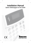
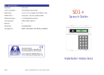
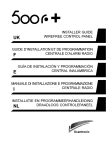
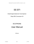
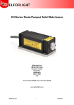
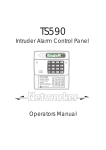
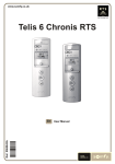
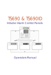
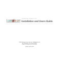
TS690R
Wireless Intruder Alarm Control
System
TS690R
SYS OPEN
SYS OPEN
Operating Instructions
Contents
System Overview
Circuit Text. . . . . . . . . . . . . . . . . . . . . . . 27
Introduction . . . . . . . . . . . . . . . . . . . . . . . 3
Control Panel Layout . . . . . . . . . . . . . . . . 4
Remote Setting Device . . . . . . . . . . . . . . 4
Remote Keypads . . . . . . . . . . . . . . . . . . 5
Fault Finding
Operating Your Alarm System
User Record. . . . . . . . . . . . . . . . . . . . . . 30
Detection Circuit Record. . . . . . . . . . . . 30
Service Record . . . . . . . . . . . . . . . . . . . 32
System Details . . . . . . . . . . . . . . . . . . . . 33
Installer Information . . . . . . . . . . . . . . . . 33
Notes. . . . . . . . . . . . . . . . . . . . . . . . . . . 34
Introduction . . . . . . . . . . . . . . . . . . . . . . . 6
Full Setting The System. . . . . . . . . . . . . . . 7
Full Setting with the Remote Setting Device
................................7
Unsetting the system . . . . . . . . . . . . . . . . 8
Unsetting with the Remote Setting Device8
Part Setting The System . . . . . . . . . . . . . . 9
Part Setting with the Remote Setting
Device . . . . . . . . . . . . . . . . . . . . . . . . . . 9
Unsetting After an Alarm . . . . . . . . . . . . 10
Resetting After an Alarm . . . . . . . . . . . . 10
User Menu 1
Introduction . . . . . . . . . . . . . . . . . . . . . . 12
Bell Test . . . . . . . . . . . . . . . . . . . . . . . . . 13
Walk Test . . . . . . . . . . . . . . . . . . . . . . . . 14
Remote Reset . . . . . . . . . . . . . . . . . . . . 14
Change Passcode . . . . . . . . . . . . . . . . 15
Enable Chime . . . . . . . . . . . . . . . . . . . . 15
Omit Circuits . . . . . . . . . . . . . . . . . . . . . 16
Silent Set . . . . . . . . . . . . . . . . . . . . . . . . 17
Full Set and Part Set. . . . . . . . . . . . . . . . 17
User Menu 2
Introduction . . . . . . . . . . . . . . . . . . . . . . 18
View Circuits . . . . . . . . . . . . . . . . . . . . . 19
Set Clock. . . . . . . . . . . . . . . . . . . . . . . . 19
Set Date . . . . . . . . . . . . . . . . . . . . . . . . 20
Setup New Users . . . . . . . . . . . . . . . . . . 21
Alter Chime Circuits. . . . . . . . . . . . . . . . 23
Print System Log . . . . . . . . . . . . . . . . . . 23
Configure Part Sets . . . . . . . . . . . . . . . . 24
View Log . . . . . . . . . . . . . . . . . . . . . . . . 25
Event Log Codes. . . . . . . . . . . . . . . . . . 26
2
Display Messages . . . . . . . . . . . . . . . . . 28
System Records
System Overview
Introduction
The TS690R is an advanced wirefree security alarm control system using state of the art
electronics to provide comprehensive but flexible protection for both domestic and small
commercial premises. The system comprises of a number of components linked to a
central control unit. The TS690R can monitor up to 30 wirefree devices and can also
monitor up to 8 conventional hard wired circuits.
The system can be operated from the keypad on the control panel or from one of four
remote keypads. Detection devices such as door contacts or movement sensors are
allocated to detection circuits which are identified on a 8 character Liquid crystal display
(LCD).
Each alarm installation is specific to the site and its occupier and may differ from other
TS690R installations. This manual describes in detail all the functions and procedures
available to the user, however, not all these may be relevant to the way your system is set
up. To avoid unnecessary operating errors please discuss the details of the alarm system
with your alarm company before attempting to use it. Also ensure that alarm company
has completed the system record sheets at the back of this manual.
3
Control Panel Layout
TS690R
1
SYS OPEN
2
3
1.
2.
3.
Display - A backlit 8 character Starburst Liquid crystal display used to show system
status etc.
Keyboard - Used for operating your alarm system.
Part Set Buttons - Used to select part modes A, B or C.
Remote Setting Device
The 525r remote setting device allows you to full set, part set, unset and generate a panic
alarm.
1.
2.
3.
NIGHT - Used to part set (Part Set A Only) the alarm
system.
OFF - Used to unset the alarm system.
w
4
1
ARM - Used for full setting the alarm system.
Pressing the “ARM” and the “OFF” buttons at the
same time will cause a panic alarm, i.e. full
internal and external alarm.
PANIC
4.
Activity LED - Flashes when any button is pressed to
show that signal has been transmitted.
ARM
2
NIGHT
3
4
OFF
5
Remote Keypads
Your alarm system can be operated from one or more remote keypads, which will have
been strategically located within the protected premises. The remote keypads may be
one of two types.
Arming Station
The remote arming station can only be used to full set, part set and unset your alarm
system.
1.
2.
3.
Power Indicator - Flashes if no mains
power is present. Steady when mains
power is present.
Ê
Ë
Function Indicator - Programmed by the
alarm company, can indicate a fault, set
etc.
Keyboard - Used for operating your alarm
system.
Ì
Starburst Keypad
The Starburst remote keypad is a full function keypad and can be used to program, test, set
and unset the alarm system.
Ê
Ë
1.
2.
3.
Power Indicator - Flashes if no mains
power is present. Steady when mains
supply is present.
Starburst Display - Used to show the
system time along with other system
messages.
SYS OPEN
Keyboard - Used for operating your alarm
system.
Ì
5
Operating Your Alarm System
Introduction
Remote Setting Device
If your system has been supplied with a remote setting device, the full setting, part setting
and unsetting of your alarm system can be performed by simply pressing the relevant
button on the remote setting device.
Passcodes
Access to the system is gained by entering a 4 digit passcode. Every time you wish to use
the system your passcode must be entered correctly.
User Types
The TS690R can have up to 10 separate users each user is assigned a passcode, and a
user level. The user level defines what the user can access within the user menus, for a
definition of each user level see “Setup New Users” page 21.
User Menus
The system has 2 users menus, with each menu having between 9 and 10 options. User
menu 1 is accessed by entering your passcode followed by the [ENT] key. Access to user
menus and options will depend on your user level. When a menu option is selected you
may abandon the option by pressing the [ESC] key. To leave the user menus and return the
system to its original state simply keep pressing the [ESC] key until the display shows “OPEN”.
Engineer on site
When your alarm company has an engineer on site and is logged into the system, the
keypads will show “ENGINEER ON SITE”. You can continue to operate the system as normal,
if required. The message is automatically cleared when the engineer logs off.
6
Full Setting The System
The full setting procedure can be initiated from the control panel or via a remote keypad (if
one is fitted). Before attempting to full set the alarm system ensure that all movement
detectors are unobstructed and all doors, and windows are secure.
1.
From the unset (open) mode enter your passcode.
2.
After 5 seconds the exit sounder will start and the display
will show the remaining exit time.
3.
Leave the premises by the designated exit route, close 1
the final door and press the exit terminator button (if
fitted). The system is fully set when the exit sounder stops.
w
To abandon the setting process any time, simply
re-enter your passcode.
w
If the display shows “9999" at step 2 the system is
configured set by exit terminator or on closure of the
last exit circuit.
w
If an attempt is made to full set the system whilst one
or more circuits are active (such as a door being
open) the display at step (2) will indicate the circuit(s)
that are in fault and internal sounder generates an
interrupted tone. The fault must be cleared before
the setting procedure can be completed. If the fault
is still present at the end of the exit time an internal
alarm will be generated. If fitted, the external strobe
light will flash indicating that the system has “Failed to
set”. To prevent this alarm simply re-enter your
passcode before the exit timer expires.
SYS OPEN
? ? ? ?
SEL FUNC
2
EXIT 029
3
FULL SET
20-27
Full Setting with the Remote Setting Device
If your system has a 525r remote setting device you can set full set the system as follows:
1.
Press the [ARM] button on the remote setting device, the exit sounder will start and
the display will show the remaining exit time.
2.
Leave the premises by the designated exit route, close the final door and press the
exit terminator button (if fitted). The system is fully set when the exit sounder stops.
7
Unsetting the system
The unsetting of the alarm system can be performed at the control panel or a remote
keypad (if one is flitted).
1.
2.
Enter the premises via the prescribed entry route and
proceed directly to the control panel or remote keypad. 1
The internal sounders generate an interrupted tone. The
display will show the remaining entry time.
Enter your 4 digit passcode before the entry timer expires.
The internal sounders will stop and the display will show 2
“SYS OPEN”. After 5 seconds the “SYS OPEN” message will
disappear and the display will show the time.
w
If the entry time is exceeded an alarm is generated
from the internal sounders and the “Second Entry”
timer is started. If at the end of the “Second Entry”
timer the alarm system has not been unset a full
alarm condition will occur. If the alarm company has
set the “Second Entry” timer to zero the full alarm will
occur when the first entry timer expires.
w
If during the entry procedure the user strays from the
prescribed entry route and activates a detection
circuit a full alarm will occur (internal sounders and
external sounders). If the alarm system is fitted with a
remote signalling device this will also be triggered.
ENT CODE
? ? ? ?
SYS OPEN
Unsetting with the Remote Setting Device
If your system has a 525r remote setting device you can unset set the system as follows:
1.
Enter the premises via the prescribed entry route. The internal sounders generate an
interrupted tone. The display will show the remaining entry time.
2.
Press the [OFF] button on the remote setting device, the entry sounder will stop and
the display will show “SYS OPEN”. After 5 seconds the “SYS OPEN” message will
disappear and the display will show the time.
8
Part Setting The System
The TS690R can have up to three predefined part set configurations. Each configuration
allows the alarm system to set with one or more circuits isolated. Normally the alarm
company will configure each part set option, however the master user may also configure
the part sets, providing the alarm company has programmed the alarm system to allow
this facility.
1.
From the unset (open) mode enter your passcode.
2.
Select the required part set mode by pressing [A], [B] or
[C].
3.
4.
Either press [ENT] when the display shows the required
part set mode or wait for 5 seconds after which the exit
sounder will start and the display will show the remaining
exit time.
Leave the area by the designated exit route, close the
final door and press the exit terminator button (if fitted).
The system is part set when the exit sounder stops.
SYS OPEN
1
? ? ? ?
SEL FUNC
2
A
B
C
P / SET A
3
EXIT 035
4
P / SET A
17-3 1
Part Setting with the Remote Setting Device
If your system has a 525r remote setting device you can part set (Part Set A Only) the system
as follows:
1.
Press the [NIGHT] button on the remote setting device, the exit sounder will start and
the display will show the remaining exit time.
2.
Leave the area by the designated exit route, close the final door and press the exit
terminator button (if fitted). The system is part set when the exit sounder stops.
9
Unsetting After an Alarm
If an alarm has occurred whilst the alarm system is full or part set, the display will indicate
the detection circuit that was triggered when you unset the system. Once the cause of the
alarm has been established the system must be reset, see “Resetting after an alarm” on
page 10.
1.
2.
3.
Enter the premises via the prescribed entry route and
proceed directly to the control panel or remote keypad.
The internal sounders generate an interrupted tone. The
display will show the remaining entry time.
Enter your 4 digit passcode before the entry timer
expires. The internal sounders will stop and the display
will show the circuit that caused the alarm.
Refer to “Resetting After an Alarm” on page 10.
w
17-31
1
ENT CODE
2
If circuit text has been programmed then the display
will alternate between the circuit number and the
circuit text at step (2).
? ? ? ?
ALARM 03
Resetting After an Alarm
Your alarm company will have programmed the system to be either “User Reset”,
“Engineer Reset” or “Remote Reset”, consult your alarm company if you are not sure.
User Reset
If your system has been programmed as user reset, alarms can be reset by any user that
has valid passcode.
From step (3) of “Unsetting After an Alarm”, proceed as follows:
1.
Enter your passcode and within 5 seconds press [ESC].
2.
The system is now reset and back in the open mode. After 1
5 seconds the “SYS OPEN” message will disappear and
the display will show the time.
10
ALARM 03
? ? ? ? +
SYS OPEN
Resetting After an Alarm (Cont.)
Engineer Reset
If your system is programmed as engineer reset, alarms can only be reset by your alarm
company.
From step (3) of “Unsetting After an Alarm”, proceed as follows:
1.
2.
3.
The display will alternate between the circuit that caused
the alarm and the “Call Engineer To Reset System” 1
message. The internal sounders will also generate a beep
every minute to remind you that the system requires
resetting.
To silence the beeps enter your passcode.
Contact your alarm company:
2
ALARM 03
CALL ENG
? ? ? ?
ALARM 03
CALL ENG
Remote Reset
If your system is programmed as remote reset, alarms can be reset by your alarm
company or via the exchange or unique passcodes.
From step (3) of “Unsetting After an Alarm”, proceed as follows:
1.
2.
3.
The display will alternate between the circuit that caused
the alarm and the “CALL ENG” message. The internal
sounders will also generate a beep every minute to
1
remind you that the system requires resetting.
To silence the beeps enter your passcode.
Enter your passcode again, the system will display a 2
unique 4 digit number. Contact your alarm company or
3
alarm receiving centre:
ALARM 03
CALL ENG
? ? ? ?
? ? ? ?
SAY ????
4.
5.
You will be asked to report the circumstances of the
alarm. If the alarm receiving centre decides you do not
require an engineer, a 4 digit remote reset code will be
given to you. Enter the 4 digit remote reset code.
After you have enter the code press the [ENT] key and
the system will return to the open condition.
4
? ? ? ?
ANS ????
5
SYS OPEN
11
User Menu 1
Introduction
User menu 1 is accessed by entering your passcode followed by [ENT]. There are 10 menu
options and access to these options will depend on your access level.
Hot Key Option
1
2
3
4
5
7
8
0
A
B
C
Page
Bell Test
13
Walk Test
14
Remote Reset
14
Change Passcode
15
Enable Chime
15
Omit Circuits
16
Silent Set
17
Full Set
17
Part Set A
17
Part Set B
17
Part Set C
17
? ? ? ?
U / MENU 1
Bell Test
1
2
3
4
5
7
8
0
A
B
C
12
+
SOUNDER9
Walk Test
WALK TST
Remote Reset
SAY 9472
Change Passcode
NEW ---Enable Chime
ENABLED
Omit Circuits
01-ARMED
Silent Set
SIL SET
Full Set
EXIT 010
Part Set A,B,C
EXIT 010
Bell Test
This option allows you to periodically test the external sounders (bell and strobe) and
internal sounders. When selected each device will operate in sequence for nine seconds.
1.
From the unset (open) mode enter your passcode and
press [ENT] to select user menu 1 (U/MENU 1).
2.
Whilst user menu 1 is selected. Press [1] to select the bell
test option.
3.
The internal sounder operates for 9 seconds, then the
external sounder operates for 9 seconds, then the
external strobe operates for 9 seconds.
4.
When all three tests are completed, the display shows
“U/MENU 1". To return the system to the open mode press
[ESC].
SYS OPEN
1
? ? ? ?
+
U / MENU 1
2
1
SOUNDER 9
3
BELLS
9
STROBE 9
4
SYS OPEN
13
Walk Test
This option allows you to test the function of individual detection circuits without causing an
alarm. As each circuit is activated the circuit number and status are displayed and the
internal sounders generate a two tone “Chime” sound. Once the test has been completed
the tested circuits can be reviewed in numerical order.
1.
From the unset (open) mode enter your passcode and
press [ENT] to select user menu 1 (U/MENU 1).
2.
Whilst user menu 1 is selected. Press [2] to select the walk
test option.
3.
Activate detection circuits in turn by opening doors with
alarm contacts and walking in front of movement
detectors.
4.
5.
When the test has been completed, press the [ESC] key.
The display will now automatically scroll through the
circuits that were tested in numerical order. The current
status of the circuit is also displayed. The [ENT] key can
be used to scroll through the tested circuits more quickly,
if desired.
Press [ESC] to leave the walk test option and return to
user menu 1. To return the system to the open mode press
[ESC].
SYS OPEN
1
? ? ? ?
+
U / MENU 1
2
2
WALK TST
3
01 GOOD
01 OPEN
4
TESTED 01 GOOD
5
SYS OPEN
Remote Reset
This option allows the user to reset the system after an alarm by using a “Remote Reset”
code. The full procedure is explained in “Resetting After an Alarm” on page 11.
14
Change Passcode
This option allows you to change your own passcode. The master users can also add and
delete user passcodes, see “Setup Users” on page 21.
1.
From the unset (open) mode enter your passcode and
press [ENT] to select user menu 1 (U/MENU 1).
2.
Whilst user menu 1 is selected. Press [4] to select the
change passcode option.
3.
4.
Enter your new passcode then press the [ENT] key. A
rising tone indicates acceptance and the system returns
to User menu 1. A low tone indicate an error and you will
be prompted to re-enter your new code.
To return the system to the open mode press [ESC].
SYS OPEN
1
? ? ? ?
+
U / MENU 1
2
4
NEW ----
3
NEW 1 2 1 2
U / MENU 1
4
SYS OPEN
Enable Chime
Detection circuits that have been programmed as “Chime”
will generate a two-tone sound when triggered. This option
allows you to enable or disable the chime option.
1.
From the unset (open) mode enter your passcode and
press [ENT] to select user menu 1 (U/MENU 1).
2.
Whilst user menu 1 is selected. Press [5] to select the
enable chime option.
SYS OPEN
1
? ? ? ?
+
U / MENU 1
2
5
ENABLED
3.
Select the chime option by pressing the pressing [B] to
alternate between enabled and disabled.
3
4.
When the display show the required setting press the
[ENT] key to accept. A rising multi-tone will be heard and
the system is returned to user menu 1.
4
5.
To return the system to the open mode press [ESC].
B
DISABLED
U / MENU 1
5
SYS OPEN
15
Omit Circuits
Occasionally it may be necessary to omit detection circuits when setting or part setting the
system. This allows the user access to the omitted area(s) when the system is set or part set.
It is also possible to omit 24hr or Auxiliary circuits so that access to these areas can be
obtained when the system is unset.
Only detection circuits that have been programmed by your
alarm company as “Omit” can be selected when using this
option.
1.
From the unset (open) mode enter your passcode and
press [ENT] to select user menu 1 (U/MENU 1).
2.
Whilst user menu 1 is selected. Press [7] to select the
omit circuits option.
3.
Select the circuit you require to omit by either entering
the circuit number or by using the [A] and [C] keys to
scroll up and down through the circuits.
4.
5.
6.
When the required circuit number is displayed press the
[B] key to alternate between “ARMED” and “OMIT”. If a
low tone is heard when pressing the [B] key the selected
circuit cannot be omitted.
When the display shows the required setting for the
selected circuit, press the [ENT] key to accept. A rising
multi-tone will be heard and the display will show the
next available circuit.
If required repeat from step (3) for other circuits, When
you have selected all the required circuits, press the
[ESC] key.
a)
b)
16
If you have selected 24hr circuits, the system will
automatically return to the unset mode and the
display will show “CCT ISOL” (Circuits Isolated).
If you have only selected night circuits, the system
will return to user menu 1. From user menu 1 you
must press [0] to full set, [A], [B] or [C] for part set.
SYS OPEN
1
? ? ? ?
+
U / MENU 1
2
7
01-ARMED
3 0 3 OR
A / C
03-ARMED
4
B
03-OMIT
5
04-ARMED
6
a
CCT ISOL
U / MENU 1
b
0 A B C
EXIT 029
Silent Set
This option you to full set or part set the system silently, i.e. no exit sounder.
1.
From the unset (open) mode enter your passcode and
press [ENT] to select user menu 1 (U/MENU 1).
2.
Whilst user menu 1 is selected. Press [8] to select the
silent set option.
3.
Press [0] to silent full set, [A], [B] or [C] for silent part set.
SYS OPEN
1
? ? ? ?
+
U / MENU 1
8
2
SIL SET
0 A B C
3
EXIT 029
FULL SET
17-31
Full Set and Part Set
This option offers an alternative method of full setting and part setting.
1.
From the unset (open) mode enter your passcode and
press [ENT] to select user menu 1 (U/MENU 1).
2.
Whilst user menu 1 is selected. Press [0] to full set the
system or [A], [B] or [C] to part set the system.
SYS OPEN
1
? ? ? ?
+
U / MENU 1
2
0 A B C
EXIT 029
FULL SET
17-31
17
User Menu 2
Introduction
User menu 2 is accessed by pressing [ENT] whilst user menu 1 is selected. There are 9 menu
options and access to these options will depend on your access level.
Hot Key Option
1
2
3
4
5
7
8
9
B
SYS OPEN
Page
View Circuits
19
Set Clock
19
Set Date
20
Setup New Users
21
Alter Chime Circuits
23
Print System Log
23
Configure Part Sets
24
View System Log
25
Circuit Text
27
? ? ? ?
+
U / MENU 1
U / MENU 2
1
View Circuits
01 GOOD
2
Set Clock
TIME ---3
Set Date
DATE ---4
Setup User Codes
USER -5
Alter Chime Circuits
0 1 QUIET
7
Log Printout
NO . . --8
Configure Part Set
P / SET A
9
View Event Log
USER 01
B
Circuit Text
CCT? --
18
View Circuits
This option allows you to ascertain the status of each detection circuit. The status for each
circuit may be as follows:
GOOD
The normal status of a detection circuit, i.e. door closed or detector healthy.
OPEN
This is the alarm status of a detection circuit, i.e. door open or detector in alarm.
TAMP
This is the tamper open circuit status of a detection circuit, i.e. alarm cable cut
or a cover removed from a detector.
LOBAT
The detector battery is low and must be replaced.
1.
From the unset (open) mode enter your passcode and
press [ENT] twice to select user menu 2 (U/MENU 2).
2.
Whilst user menu 2 is selected. Press [1] to select the view
circuits option.The display will show the status of circuit 01.
3.
4.
Select the circuit you require to view by either entering the
circuit number or by pressing the [A] and [C] keys to scroll
up and down through the circuits.
To return the system to the open mode press [ESC] three
times.
SYS OPEN
1 ? ? ? ?
+
U / MENU 2
2
1
01 GOOD
3
01 OPEN
4
SYS OPEN
Set Clock
This option allows you to adjust the system clock. The clock is
used for providing event times in the event log and is also
displayed when the system is unset or full set.
SYS OPEN
1 ? ? ? ?
1.
From the unset (open) mode enter your passcode and
press [ENT] twice to select user menu 2 (U/MENU 2).
2.
Whilst user menu 2 is selected. Press [2] to select the set
clock option.
2
3.
Enter the new time in a 24hr format, e.g. 1700 for
5:00 pm. When the display shows the correct time press
[ENT] to accept.
3
4.
To return the system to the open mode press [ESC] twice.
+
U / MENU 2
2
TIME ---1 7 0 0
TIME 1700
4
U / MENU 2
SYS OPEN
19
Set Date
This option allows you to set the system date. It is displayed in a date / month format on all
LCD remote keypads.
1.
From the unset (open) mode enter your passcode and
press [ENT] twice to select user menu 2 (U/MENU 2).
2.
Whilst user menu 2 is selected. Press [3] to select the set
date option.
3.
Enter the new date in a date/month format, e.g. 1806 for
the 18th June. When the display shows the correct date
press [ENT] to accept.
4.
SYS OPEN
1 ? ? ? ?
+
U / MENU 2
2
To return the system to the open mode press [ESC] twice.
3
DATE ----
3
1 8 0 6
DATE 1806
U / MENU 2
4
SYS OPEN
20
Setup New Users
The TS690R allows up to 10 users to operate the alarm system, each user is assigned a user
type and a passcode. User 01 is the master user which has a default setting of 5678.
User Types
The following user types are available:
1 - Master
This user type can full set, part set and unset the system. A master user
also has access to all user menus and options providing the alarm
company has programmed the master user for full access. If the
master user has been programmed for limited access the master
user cannot access user menu 2 option 8 (Configure Part Sets) and B
(Circuit Text).
2 Standard
This user type can full set, part set and unset the system. A standard
user also has access to all the options in user menu 1.
3 - Holiday
This user type can full set, part set and unset the system. A holiday user
also has access to all the options in user menu 1. However, When the
system is next unset by a master user, the holiday passcode is
automatically deleted from the system.
4 - Set Only
This user type operates in the same way as a standard user, except
that it only allows setting and part setting of the system.
5 - Reset
This user type allows unset alarm such as 24hr, fire, auxiliary to be
silenced and reset. The user type also has access to user menu 1
options 1 to 7.
6 - Duress
This user type operates in the same way as a standard user, but when
the passcode is used a silent “Panic Alarm” is transmitted to the alarm
receiving centre.
If enabled by your alarm company all users can generate a “Duress”
alarm by entering their passcode with the first two digits reversed
(e.g. for a passcode of 2580 enter 5280 to generate a “Duress”
alarm).
7 - PA
This user type does not have access to any user menus nor can it be
used to set and unset the system. When this user code is entered a
“Panic Alarm”' is transmitted to the alarm receiving centre and the
external sounder(s) and strobe light(s) are also activated.
21
Setup New Users (Cont.)
1.
From the unset (open) mode enter your passcode and press [ENT] twice to select
user menu 2 (U/MENU 2).
2.
Whilst user menu 2 is selected. Press [4] to select the
setup new users option.
3.
Enter the user number (02 - 10) that you require to setup,
then press [ENT].
1 ? ? ? ?
4.
The display shows the current type assigned for the
selected user, to change the user type press [1] - [7].
When the display shows the required user type press
[ENT] to accept.
2
5.
6.
Enter the 4 digit passcode for the selected user, then
press [ENT] to accept. A rising multi-tone indicates the
new passcode was accepted. A low tone indicates that
passcode is not available, re-enter, using a different 4
digit code.
SYS OPEN
+
U / MENU 2
4
USER -3
0 3
NOT USED
4
The system will return to step 3, if required repeat for
other users or press [ESC] three times to return the
system to the open mode.
1
7
MASTER
NEW ---5
2 5 8 0
NEW 2580
6
USER -SYS OPEN
22
Alter Chime Circuits
This option allows you to select which detection circuits will cause a chime tone when
triggered. Once programmed, users that have access to user menu 1 can select one of
the four chime options, see “Enable Chime” on page 15.
1.
From the unset (open) mode enter your passcode and
press [ENT] twice to select user menu 2 (U/MENU 2).
2.
Whilst user menu 2 is selected. Press [5] to select the
alter chime circuits option.
3.
Select the required circuit by either entering the circuit
number or by using the [A] and [C] keys to scroll up and
down through the circuits.
4.
5.
When the required circuit is displayed, press [B] to
alternate between “QUIET” and “CHIME”. When the
display show the required setting press [ENT] to
accept. A rising multi-tone will be heard and the next
available circuit is displayed.
Repeat from step 3 for other circuits or press [ESC] three
times to return to the open mode.
SYS OPEN
1 ? ? ? ?
+
U / MENU 2
2
5
0 1 - QUIET
3
0 6
06 - QUIET
4
B
06 - CHIME
5
07 - QUIET
SYS OPEN
Print System Log
The system log stores 150 events. If a printer is connected to
your alarm system it is possible to print a selected number of
log events.
1.
From the unset (open) mode enter your passcode and
press [ENT] twice to select user menu 2 (U/MENU 2).
2.
Whilst user menu 2 is selected, press [7] to select the print
system log option.
3.
4.
Enter the number of events to be printed (001 - 150). Press
[ENT] to start the printout. To cancel printout repeat from
step 2 and enter “000” for the number of events.
SYS OPEN
1 ? ? ? ?
+
U / MENU 2
2
7
NO . .---
3
1 5 0
NO . . 150
To return the system to the open mode press [ESC] twice.
U / MENU 2
4
SYS OPEN
23
Configure Part Sets
The TS690R can be configured to have up to three part set modes (Part Set A, Part Set B and
Part Set C). This option allows the master user to configure each part set mode. Within each
part set mode you must designate which circuits will remain armed and which circuits will
be omitted. When the relevant part set mode is selected the system only arms the circuits
that are designated as armed and isolates the circuits that are designated as omitted.
1.
From the unset (open) mode enter your passcode and
press [ENT] twice to select user menu 2 (U/MENU 2).
2.
Whilst user menu 2 is selected. Press [8] to select the
configure part sets option.
3.
Select the part set mode you require to setup by pressing
[A], [B] or [C] then [ENT].
4.
Select the required circuit by either entering the circuit
number or by using the [A] and [C] keys to scroll up and
down through the circuits.
5.
When the required circuit is displayed, press [B] to
alternate between “ARMED” and “OMIT”. An armed circuit
will remain armed when the system is part set, an omit
circuit will be isolated when the system is part set. When
the display shows the required setting press [ENT] to
accept. A rising multi-tone will be heard and the next
available circuit is displayed.
6.
Repeat from step 3 for other circuits or press [ESC] three
times to return to the open mode.
SYS OPEN
1 ? ? ? ?
+
U / MENU 2
8
2
P / SET A
3
A
B
C
P / SET B
01 - ARMED
4
0 8
08 - ARMED
5
B
08 - OMIT
09-ARMED
6
SYS OPEN
24
View Log
The TS690R stores up to 150 events in the log. This option allows you to view each event.
1.
From the unset (open) mode enter your passcode and
press [ENT] twice to select user menu 2 (U/MENU 2).
2.
Whilst user menu 2 is selected. Press [9] to select the view
log option.
3.
The display will show the most recent event, see table 1
for event codes. To navigate through the log, use the [A]
and [C] keys to scroll backwards and forwards.
4.
5.
The [B] key can be used to display additional information
for the select event. The first press shows the time that
event occurred, the second press shows the date, the
third press bring you back to the event type.
To return the system to the open mode press [ESC] three
times.
SYS OPEN
1 ? ? ? ?
+
U / MENU 2
2
9
USER 01
3
A / C /
ALARM 03
4
B
1 8 . 47 . 51
B
01/01
B
ALARM 03
5
U / MENU 2
SYS OPEN
25
Event Log Codes
AC OFF
Mains power removed
AC ON
Mains power restored
ALARM 01-38
Full alarm from circuit 01-38
AUX 01-38
Auxiliary alarm from circuit 01-38
AUX TAMP
Auxiliary tamper alarm
BATT FLT
Battery fault (voltage below 10.5V)
BELL TST
Bell test performed
C TMP 01-04
Code tamper from keypad 01-04
CCT ISOL
24hr circuits isolated
DATE CHG
System date changed
DEFLT 01
User 01 reset to 5678 by the engineer
DURS 01-10
Duress alarm from user 01-10
E ALM 01-38
Entry time-out alarm from circuit 01-38
ENTRY 01-38
Entry timer started by circuit 01-38
FACT RST
System “Factory Restarted”
FIRE 01-38
Fire alarm from circuit 01-38
FIRST 01-56
The first activation of a D-Knock circuit
FOB 01-38
525r remote setting device operated
FULL SET
System full set
JAMMED
System jammed by another radio source
KEYSW 01-38
Key point operation from circuit 01-38
LID TAMP
Control panel lid removed
NO EVENT
No log event
OMIT 01-38
Circuits 01-38 omitted
OMIT REM
All omitted circuits reinstated
OMITR 01-38
Circuit 01-38 reinstated
P/SET A/B/C
System part set A, B, or C
PAALM 01-38
Panic alarm from circuit 01-38
PANIC 01-10
Panic alarm from user 01-10
R ADD 01-04
Remote keypad added to the system
R REM 01-04
Remote keypad removed from system
R TMP 01-04
Remote keypad tamper
REARMED
System re-armed all healthy circuits
REM RST
System reset by “Remote Reset” code
SET FAIL
System failed to Set
SITE RST
System “On-Site” restart
SYS OPEN
System fully unset
TAMP 01-38
Tamper alarm from circuit 01-38
TC OFF
All circuits taken off “Test”
TESTD 01-38
Number of circuits tested during a walk test
T FAIL 01-38
Circuit failed during “Test”
TIME CHG
System time changed
USER 00-10
User code entered 00-10
WALK TST
System “Walk Test” selected
26
Circuit Text
Each detection circuit can have up to 8 characters of text assigned to it. This option allows
you to program / edit the circuit text.
1.
From the unset (open) mode enter your passcode and
press [ENT] twice to select user menu 2 (U/MENU 2).
2.
Whilst user menu 2 is selected. Press [B] to select the
circuit text option. If you here a low tone, you are not
permitted to change circuit text.
1 ? ? ? ?
3.
Enter the circuit number (two digits) then press [ENT].
2
4.
The cursor (*) will flash on and off in the first character
position on the display.
5.
1
4
7
[
A
Use the keys as shown below to edit the text:
A
O
Cursor left
Accept text
Next character
2
5
8
0
B
E
U
Not used
Space
Erase all text
3
6
9
]
C
I
0 (zero)
SYS OPEN
U / MENU 2
3
4
Repeat from step 3 for other circuits or press [ESC] three
times to return to the open mode.
x
e.g. to enter "HALL PIR"
[3] [C] = "H"
[9] = cursor right
[1] = "A"
[9] = cursor right
[3] [A] [A] [A] = "L"
[9] = cursor right
[3] [A] [A] [A] = "L"
[9] [9] = cursor right x 2
[4] [A] = "P"
[9] = cursor right
[3] = "I"
[9] = cursor right
[4] [A] [A] [A] = "R"
Prev. character
7.
Enter Circuit No
5 Use keys to edit text
Abort
When the display shows the required text press [ENT] to
accept.
B
CCT?--
Cursor right
6.
+
HALL PIR
6
CCT?-7
SYS OPEN
27
Fault Finding
Display Messages
Displays
Description
AC OFF
There is no mains power to the control panel and the alarm system is now
running on its standby battery. The system will also generate a chime tone
every minute to warn you that the fault exists, to silence the chime tones
simply enter your passcode. If the mains power is not restored you may not
be able to set the alarm system. If the fault persists the standby battery will
eventually run flat. Contact your alarm company for further advice.
ALARM 05
A full alarm has occurred from a detection circuit (circuit 05). This message
is normally display after unsetting the alarm system. Before the system can
be set again the alarm system must be reset, see “Resetting After an Alarm”
on page 10.
AUX 06
An auxiliary alarm has occurred from a detection circuit (circuit 06). The type
of alarm is silent and will activate the appropriate outputs. To reset the alarm
simply enter your passcode followed by [ESC].
AUX TAMP
The control panel auxiliary or bell tamper circuits have been activated. If the
fault is not cleared you will not be able to set the alarm system. To silence the
alarm simply enter your passcode. Contact your alarm company for further
advice.
BATT FLT
The alarm system standby battery has developed a fault, normally because
the system mains power is not present. If the fault is not cleared you will not
be able to set the alarm system. To silence the alarm simply enter your
passcode. Contact your alarm company for further advice.
C.TMP 02
A passcode has been incorrectly entered more than four times at a remote
keypad (keypad 02). To silence the alarm enter a correct passcode. To
reset the alarm simply enter your passcode follows by [ESC].
E ALM 01
An entry time out alarm has occurred from a detection circuit (circuit 01).
This is normally caused when the entry procedure is started and the system is
not unset before the timer expires. Before the system can be set again the
alarm system must be reset, see “Resetting After an Alarm” on page 10.
FIRE 07
A fire alarm has occurred from a detection circuit (circuit 07). The internal
sounder will generate a distinctive fire alarm tone and the external sounder
is pulsed on and off. To silence the alarm simply enter your passcode. To
reset the alarm simply enter your passcode again followed by [ESC].
JAMMED
The system is being jammed by another radio source using the same
frequency as the detectors. To silence the alarm simply enter your
passcode. Contact your alarm company for further advice.
28
Display Messages (Cont.)
BUSY
Another user is operating the alarm system from another remote keypad.
When they have finished all remote keypads will revert to normal operation.
LID TAMP
The lid of the control panel has been removed. If the fault is not cleared you
will not be able to set the alarm system. To silence the alarm simply enter
your passcode. Contact your alarm company for further advice.
01-LOBAT
The detector is in a low battery state (circuit 01). The system will generate a
warning tone every 30 seconds as a reminder. To silence this alarm simply
enter your passcode. The battery must be replaced as soon as possible.
PA ALM 08
A panic alarm (PA) has occurred from a detection circuit (circuit 08). To
silence the alarm simply enter your passcode. Reset the panic alarm
device if required (normally with a key). To reset the alarm simply enter your
passcode again followed by [ESC].
R TMP 01
The lid of a remote keypad has been removed (remote 01). If the fault is not
cleared you will not be able to set the alarm system. To silence the alarm
simply enter your passcode. Contact your alarm company for further
advice.
SET FAIL
The system has failed to set. This normally caused by a circuit being left
open at the time of setting. Check that all circuits are healthy before
attempting to set the alarm system.
TAMP 02
A tamper alarm has occurred from a detection circuit (circuit 02). Normally
caused by removing the cover from a movement sensor or a break in the
circuit cabling. To silence the alarm simply enter your passcode. If the fault is
not cleared you will not be able to set the alarm system. Contact your alarm
company for further advice.
29
System Records
User Record
User
01
Type
Name
Master
02
03
04
05
06
07
08
09
10
Detection Circuit Record
Circuit
01
02
03
04
05
06
07
08
09
10
11
12
30
Location
Omit
Chime
P.Set A
P.Set B
P.Set C
Detection Circuit Record (Cont.)
Circuit
Location
Omit
Chime
P.Set A
P.Set B
P.Set C
13
14
15
16
17
18
19
20
21
22
23
24
25
26
27
28
29
30
31
32
33
34
35
36
37
38
31
Service Record
Date
32
Engineer
Action
System Details
Entry Time
Exit Time
Bell Delay
Bell Duration
Full Set By
Part Set A by
Part Set B by
Part Set C by
Reset by
Set with mains off
Installer Information
Installation Engineer:
Alarm Company:
Address:
Telephone No.:
Alarm Receiving Centre:
Telephone No.:
Date Installed:
33
Notes
34
Notes
35
18028
Drg Number 33:1969 Issue 02 Doc 02 January, 1998