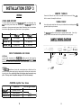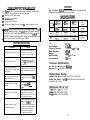
1
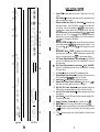
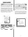
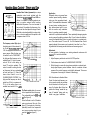
SOUNDSTRE/4lVI@
T
E
C
H
N
0
L
0
G
I
E
S
RUBICON
502
702
1002
Power Amplifiers
SOUNDSTREAM@
T
E
C
H
lV
0
L
0
G
SOUNDSTREAM TECHNOLOGIES
120 Blue Ravine Road . Folsom - California 95630 USA
ph 916.351.1288 . fax 916.351.0414
rev 8 - 30 O/98
I
E
S
Owner’s Manual
and
Installation Guide
Table of Contents
Conaratulations!
You now own the Soundstream RUBICON amplifier, the product of an uncompromising design and engineering philosophy. Your Soundstream
RUBICON amplifier will outperform any other amplifier in the world.
Design Features .............................................................
p4-5
Rubicon Amplifier Diagram ............................................ ~6-7
To Maximize the performance of your system, we recommend that you thoroughly acquaint yourself with its capabilites and features. Please retain this
manual and your sales receipt for future reference.
Soundstream amplifiers are the result of American innovation and the highest quality control standards. When properly installed, they will provide you
with many years of listening pleasure. Should your amplifier ever need service or replacement due to theft, please record the following information which
will help protect your investment.
Crossover Adjustments .................................................. p8-9
Hawkins Bass ControlTM Theory and Use ...................... p 10 - 11
Installation: Speaker Output Modes ............................... PI2
Installation: Balanced / Unbalanced Inputs .................... p 13
Model and Serial #
Installation: Wiring and Diagram .................................... pl4-15
Dealer’s Name
Date of Purchase
Installation: Mounting ..................................................... Pl6
Installation Shop
Installation: Level Setting and Front Spoiler. .................. p 17
Installation Date
Protection Circuitry and Troubleshooting ....................... p 18
2
Service ...........................................................................
PI9
Specifications .................................................................
PI9
3
RUBITM(_Rapid-Be _Branched -Impulse) This new proprietary power supply topology eliminates “power sags” during low frequency reproduction
by rapidly increasing the duty cycle, stabilizing the power supply and
allowing it to deliver the power required when reproducing low frequencies. Also, greater reserve gate power is stored for low voltage conditions that occur during extreme conditions.
STACTTM (STabilized Apex orrent _Topology) Reduces power supply
stress by 50%. Typical designs degrade the stereo image due to phase
reversal of even-order harmonic distortion that occurs between the inverted channels. In the STACT design, inversion is done at the power
amplifier drive stage. Since the fully symmetrical power amplifier produces no even-harmonic distortion itself and all preamplifier circuitry is
run completely in-phase, no even harmonic distortion phase reversal
occurs.
4
TridentTM Protection Topology provides three types of protection:
1. Output protection against short circuits or improper loads.
2. Ground fault detection: Shuts down the amplifier when a significant
voltage (> Welts) fluctuation occurs between electrical (turn-on lead)
and battery ground.
3. Thermal Protection: Puts the amplifier into thermal rollback or shuts
the amplifier down in extreme thermal conditions.
Hawkins Bass Control - Fully adjustable subwoofer equalizaton circuit
providing frequency and boost (“Q”) adjustment for optimum subwoofer
performance. A frequency tracking subsonic filter protects woofers from
potentially harmfull low frequency information and maximizes output in
a usable range.
Harmonic Bass Alignment TM The 2nd and 3rd order harmonic peaks
are critically aligned to fundamental peaks at low frequencies. This
produces tighter, more accurate bass reproduction.
Drive Delay II TM Amplifier section powers up 2 to 3 seconds after the
power supply eliminating turn-oncand off pops. The turn off process is
reversed: Amplifier section turns off first, followed by the power supply.
4
Output Clipping Indicators indicate clipping on the output stage of
the amplifier. Monitoring the clipping indicators allows the user to achieve
maximum Sound Pressure Level without clipping the amplifier.
Dynamically Optimized Power Grid TM . Power grid is evenly distributed between primary and secondary power supplies, providing greater
dynamics and improved RF filtering.
Auto High CurrentTM automatically matches the amplifier to the load
being driven allowing greater system flexibility, greater output, higher
reliability, and high efficiency 1 ohm (stereo) operation.
ChassisinkTM All transistors are ideally located and sandwiched between the circuit board and the heatsink to provide coo efficient amplifiea operation.
Differentially Balanced RCA Input eliminates grou id loop related
noise in the audio.
Fully Balanced 6-pin DIN Input for professional-quality performance
and noise cancellation. The 6-pin DIN plug carries (*) signal information for Left and Right channels, audio ground, and * 15 Vdc to operate
the Soundstream BLT / BLT4 Balanced Line Transmitters.
Continuously Variable Crossover Networks: 12 dB/Octave highpass
variable from 70 to 160 Hz, and 24 dB/Octave lowpass crossovers variable from 55 to 220 Hz.
Flexible Dual Input Level Control allows 300 mV to 5 V input sensitivity Separate Left and Right level controls allow user to optimize
system level control.
Symmetrical Discrete Balanced Class A Drive Boards Auto-adjust
for linear performance while driving low impedance loads.
Removable Front Spoiler allows for stealth installation of RCA, Balanced Line, Speaker and Power wiring.
5
KEY TO CALLOUTS
8
1.
Power LED - Indicates amplifier power, either in High Power or Auto High
2.
Clip Indicators - Indicates the signal output level is too high and the output
Current.
stage of the amplifier is clipping.
3.
4.
5.
6.
7.
8.
9.
10.
Il.
12.
-16
-17
-18
13.
14.
15.
16.
17.
18.
19.
Subsonic, Hawkins Bass Control, H.P. Xover Switch - Selectable high pass
filter frequency range. Select “SUB SONIC” to engage the Sub Sonic filter
with no boost. Use the knob indicated by callout #I2 to set the frequency:
13-30Hz). Select “Hawkins Bass Control” to engage the Sub Sonic filter
with available boost. Use the knob indicated by callout #I2 to set the
frequency: 30 Hz to 70 Hz. Select “H.P. XOVER” to engage the amplifier’s
high pass filter for running satellite speakers. Use the knob indicated by
callout #I2 to set the frequency: 70-I 60 Hz.)
Low Pass XOVER Switch - Selectable low pass filter for driving subwoofers.
Use the knob indicated by callout #I3 to set the low pass frequency. Note:
Do not have the *‘L.P XOVER” and the “HR XOVER” engaged at the same
time.
MONO/SUM/ST Switch - “MONO” for bridged mono operation with a single
input signal (right channel only). ‘SUM” for bridged mono operation summing two input signal (left and right). “ST’ for normal stereo operation,
Left Channel Balanced/Unbalanced Input Selector - Select “BALANCED”
to use the 6 pin Balanced signal input. Select “UNBALANCED” to use the
RCA signal inputs.
Right Channel Balanced/Unbalanced Input Selector - Select “BALANCED”
to use the 6 pin Balanced signal input. Select “UNBALANCED” to use the
RCA signal inputs.
RCA Inputs - Right and Left channel RCA (Unbalanced) inputs.
Balanced Signal Input Connector - 6-Pin Balanced input connector for use
with the Soundstream BLT/BLT4 Balanced Line Trasmitter.
Input Levels - Independent Left and Right input level controls.
Hawkins Bass Control “Boost” Adjustment - Varies from 0 to +9 dB of
boost when the Hawkins Bass Control circuit is engaged.
High Pass Filter Control Adjustment - Frequency adjustment control for the
High Pass filter, the Hawkins Bass Control filter, or the Sub Sonic filter.
Low Pass Filter Control Adjustment - Frequency adjustment control for the
Low Pass filter.
Line Outputs - Line level RCA outputs to drive an external amplifier (Note:
The outputs are full-range.)
Speaker Connection Terminal - Speaker connections for Ch’s 1 & 2.
REMOTE - Remote turn-on input from the head unit. Accepts +12V.
GND - Main ground connection. Bolt to a clean chassis point in the vehicle.
+12V - Connected to a fuse or circuit breaker, then to the battery’s positive
terminal
FUSE - Main power supply fuse. Warning: Replace only with the same
value fuse!
Front View
6
7
The RUBICON amplifiers incorporate an on-board staggered electronic crossover, with RCA outputs to drive an external amplifier. No
external electronic crossover is necessary. The high and low pass
portions of the crossover can be set independently of one another.
To engage the High Pass filter, set the left crossover switch on the
top of the amplifier to “H.P. X-OVER”, and use the frequency adjustment knob marked “H.P. X-OVER”. To engage the Low Pass filter,
set the left crossover switch to either “SUB SONIC” or “HAWKINS
BASS CONTROL” (see pages 1 O-1 1 for more details), and set the
right crossover switch “L.P. X-OVER” to the “IN” position.
In many car audio installations, there is a tendency for a “midbass
boom.” Because of their interior dimensions, most cars will resonate or ring at these midbass frequencies. If we design the system
so there is reduced output in this region, the final response is very
smooth and natural sounding. The high pass cossover is independently variable from 70 to 160 Hz at 12 dB/Octave, and the low pass
crossover is independently variable from 55 to 220 Hz at 24 dB/Octave.
For initial crossover setup, try setting the low pass filter to approximately 60 Hz, and the high pass filter to approximately 100 Hz.
Change the crossover points to accommodate a good mixture of
frequency response, power handling, and personal preference.
Cros
Crossover
I
.L P
XOVER
12 d6Dctave High Pass
H P XOVER-73 192 Hz
HA’NWS l 30 70Hz
SLBSCNC l 13 30Hz
’
24 dB/Octave Low Pass
blF~R7%N~ Do not have the law Pass filter and the High
Pass filter buth engaged at the same time. While this won’t
damage the amplifier, the frquency range of the amplified signal will be severJ’y limited.
.
9
su8 rlTml KVER
SONIC
HAWKINS
BASS
CONTROL
r HAWKINS 1
FREQ
FREQ
BOOST
110
Hawkins Bass Control (parametric) is a unique
subwoofer control circuit included with the
Soundstream RUBICONSM, 702 and 1002 amplifiers. It is capable of removing subsonic energy in program material while boosting
subwoofer frequencies. The circuit consists of
two controls. One adjusts the frequency of operation and the other adjusts the range of boost.
With both controls adjusted fully counter-clockwise, no boost is applied and the amplifier is flat
in response down to 20 Hz.
FIG. 1 BASS CONTROL
10
The frequency control (Hz) adjusts
the starting point of the subsonic filter. On the RUBICON502,702 and
1002, the high pass filter has two frequency ranges. When the bass control switch is set to “SUB SONIC”,
the high pass filter frequency can be
adjusted from 13 Hz up to a maximum of 30 Hz. In this setting, no
boost “Q” control is available. This
control is useful for setting the lowest frequency that your subwoofer
will see (see figure 1). When the
bass control switch is set to
“HAWKINS BASS CONTROL”, the
high pass filter frequency can be adjusted from 30 Hz to a maximum of
70 Hz. In this setting, there is an
available boost control of 0 to +9 dB.
10
1
I
I
5
0
dB
-5
-10
-15
-20
-25
I
-3010
I
Frequency (Hz)
I
IIIIIII
50
100
FIG. 4 VARIABLE BOOST
200
1
5
0
dB
-5
-10
Adjustment
An easy method of optimizing your existing subwoofer enclosure with
Hawkin’s “Hz” control is as follows.
-15
-20
-25
-30 lOFrequency
50
100
200
FIG. 2 VARIABLE “Q”
10
5
0
dB
Application
80
70
Subwoofer drivers in general have
60
excellent power handling character5.0
istics over their operational band- (,?I$0
30
width. This bandwidth is determined
20
by many factors, including driver deIO
sign, and enclosure type. It is pos0.0
100
200
10 Frequency(Hz)
50
sible to overdrive any subwoofer
FIG. 5 LIMITED EXCURSION
driver by sending powerful signals
outside of its operational bandwidth. These potentially damaging signals
can be removed by adding a subsonic filter. Figure 5 shows the effectiveness of the Hawkins Bass Control on woofer excursion in a vented enclosure. The woofer travels 7.5 mm at 10 Hz. With Hawkins Bass Control
properly adjusted, this excursion can be reduced to less than 1 mm. This is
of great benefit to lowering woofer distortion and increasing output.
-5
-10
-15
1.
Adjust frequency and boost control to full CCW position.
2.
Set the bass control switch to “HAWKINS BASS CONTROL”.
3.
While listening to music with strong bass content at a moderate level,
slowly adjust frequency control clockwise. Listen for a reduction of bass
response. Now, rotate frequency control slightly backwards. This serves
the purpose of removing the “subsonic” bass energy.
-20
-25
-30
10 Frequency(Hz)
FIG. 3 VARIABLE HIGH PASS
The Boost control adjusts the amount
of level applied at the set frequency.
This is adjustable from flat (OdB) to +9
dB. (See figure 2)
When the Boost is set to 0, Hawkins
acts as a sub-sonic filter only. (See
figure 3) The simple act of removing
potentially harmful low frequencies
can improve system output by as
much as 3 dB. (see figure 4)
10
With Soundstream’s Hawkins Bass
Control, the boost and frequency control can provide virtually any combination of boost and cut to suit your designs. So, Hawkins Bass Control can
provide the “tailoring” needed for any
type of “assisted” design and any
woofer in any type of installation.
10
5
0
dB
-5
-10
-15
-20
-25
-30 10 Frequency(Hz)
50
100
FIG. 6 VARIOUS SETTINGS
11
200
[ INSTALLATION STEP 1
The RUBICON502, 702 and 1002 amplifiers have the ability to operate in any
one of the following modes:
Stereo @TACT/Mixed Mono); Use this mode for either stereo operation (left
and right channels) or for Mixed Mono operation (stereo left and right channels
plus bridged mono for a subwoofer).
INSTALLATION STEP 2
The RUBICON502, 702 and 1002 amplifiers have the ability to accept either a
standard Unbalanced RCA signal input, or a Balanced “Pro Audio” style input
signals with the use of the Soundstream BLT Balanced Line Transmitter or some
other balanced line audio source. Before installing your system, you should
decide upon which signal type you wish to run, There are advantages to both:
UNBALANCED INPUT
Summed Mono: Use this mode to get a bridged mono output while using both
the left and right inputs and gain controls.
Bridged Mono: Use this mode to get a bridged mono output while using only
the right channel input and gain control (for use with a singular mono input).
Please follow the wiring schemes below for the correct operation:
cl
-
L+
-
SUMMED MONO
-
R+
L+
1. Improved Signal to Noise Ratio
(S/N Ratio).
2. Excellent noise cancellation
characteristics.
3. Immune to noise radiated in the
car audio environment.
The RUBICON amplifiers’ signal inputs accept a wide range of input level: from
300 mVrms to 5.0 Vrms for both Balanced and Unbalanced inputs. For the best
S/N Ratio, we recommend that the input level controls be set as far down as
possible (rotated counter-clockwise), while maintaining an acceptable level of
output.
SUMM
BRIDGED MONO
ADVANTAGES
1. Most preamplifier / source
units have Unbalanced RCA
outputs (Industry Standard).
2. No Interface module is
necessary.
BALANCED INPUT
-R+
Using the “Unbalanced” RCA Input
When using the Unbalanced RCA input, the RIGHT channel input signal switch
MUST be in the “UNBAL” position. Also, when first installing the amplifier using
this input configuration, we suggest that the left channel input signal switch be in
the “UNBAL” position as well. If vou experience alternator wine or other instal-
lation noise with both switches in the “UNBAL” position. trv movina the LEFT
channel inPut sianal switch to the “BAL” Position. This should remove any
system noise due to the installation.
Using the “Balanced” RCA Input
When using the Balanced 6-pin DIN audio input, both switches MUST be in the
“BAL” position. Also, we recommend that when using this input configuration, the
input level controls be set to the “minimum” position (rotated counter-clockwise).
The system gain should then be adjusted on the BLT Balanced Line Transmitter,
other other balanced line audio source. For the pin configuration, see the diagram below:
v
MIXED MONO
-
STEREO
L+
-
- L+
r
-
R+
1
R +
BAIANCED
I
12
+ left Signal
13
(
INSTALLATION STEP 3 ]
REMOTE TURN-ON
WIRING
Connect the “Remote” line to the turn-on lead from the source unit. When +12
Volts is received, the amplifier will turn on.
POWER AND GROUND
SIGNAL CABLE
To ensure maximum output from your RUBICON amplifier, use high quality, lowloss power and ground cables and connections. The RUBICON amplifiers will
accept up to 4 gauge power and ground cables. Determine from the chart below
the minimum gauge power and ground wire for your application.
I
I
I
I
up to 10’
up to 20’
RUBICON 502
4 or 8 gauge
4 gauge only
RUB/CON 702
4 or 8 gauge
4 gauge only
RUB/CON 1002
4 gauge only
4 gauge only
Use a high quality cable that will be easy to install and has minimal signal loss to
guarantee optimum performance.
SPEAKER CABLE
The RUBICON amplifiers will accept up to 8 gauge speaker cable. Use a high
quality, flexible, multi-strand cable for best performance and longevity.
I
CIRCUIT BREAKERS AND FUSES
I
EXTERNAL
Like all audio components, the RUBICON amplifiers must be fused near the
battery. A fuse or circuit breaker must be located within 18” of the batterv. This will
prevent a fire in the event of a shorted cable. See the chart below to determine the
correct fuse value.
To Chassis
Ground
Fuse
at the
Battery
1
I_
”
SPEAKERS
INTERNAL
The RUBICON amplifiers are fused with an automotive-type or Maxi-fuse. In the
event of a blown power supply fuse(s), replace with the correct value fuse found in
the chart below. Never replace the fuse with a higher value than what is supplied. This may result in amplifier damage and will void the warranty1
+
I-
To +lZV
Battery
Terminal
RUB/CON Amplifier Fuse Values
I
I
RUBICON 502
RUB/CON 702
I
Amplifier Fuse
I
(2) 30 amp automotive
I
80 amp
60 amp Maxi-fuse
T
80 amp
I
1 RUB/CON 1002 1
80 amp Maxi-fuse
14
I Battery Fuse / Circuit Breaker
I
I
-1
100 amp
15
’
To 2nd
Amplifier
(optIona<)
[Head Unit iw
1
f
INSTALLATION STEP 5 )
INSTALLATION STEP 4
LEVEL SETTlNG
AMPLIFIER LOCATION
The RUBICON amplifiers employ highly efficient circuitry, a custom-engineered
heat sink, and a unique Chassisink construction to maintain lower operating
temperatures. Additional cooling may be required if the amplifier is located in a
tightly confined area or when driving especially low impedance loads at extremely
high levels.
When mounting the amplifier, it should be securely mounted to either a panel in
the vehicle or an amp board or rack that is securely mounted to the vehicle. The
mounting location should be either in the passenger compartment or in the trunk
of the vehicle, away from moisture, stray or moving objects, and major electrical
components. To provide adequate ventilation, mount the amplifier so that there
are at least two inches of freely circulating air above and to the sides of it.
MOUNTING THE AMPLIFIER
a.
b.
C.
Using the amplifier as a template, mark the holes on the mounting surface.
Remove the amplifier and drill the holes for the mounting screws.
Secure the amplifier to the mounting surface using the supplied hardware.
The input levels are adjusted by means of the individual channel input level
controls located on the front of the amplifier. This is a unique dual-stage circuit
that adjusts both level and gain. This topology maintains better S/N Ratio even
when using sources with minimal output.
In the ideal situation, all components in the audio system reach maximum
undistorted output at the same time. If you send a distorted signal to an amplifier,
it is simply going to amplify distorted information. The same holds true if an
outboard processor or crossover begins to distort before you have maximum
output from the amplifier. By setting all components to reach clipping at the same
time, you can maximize the output of your system. For the RUBICON amplifiers,
follow these steps for setting the input levels:
1.
2.
3.
Turn the amplifiers’ input levels to minimum position (counter-clockwise)
Set the source unit volume to approximately 3/4 of full volume.
While playing dynamic source material, slowly increase the amplifiers’ input
level until a near maximum undistorted level is heard in the system.
The clipping indicators on the top of the amplifier let you know when the output of
the amplifier is reaching its maximum level, and has begun to clip.
WIRING
a.
b.
C.
d.
e.
f.
Run and connect the audio signal and remote turn-on cables to the amplifier from the source unit.
Carefully run the positive cable from the amplifier to a fuse or circuit breaker
within 18” of the battery.
Connect the fuse or circuit breaker lead to the battery. Leave the circuit
breaker off or the fuse out until everything is bolted down.
Secure the ground cable to a solid chassis ground on the vehicle. It may be
necessary to sand paint down to raw metal for a good connection.
Double check each and every connection!
Re-connect the fuse or circuit breaker.
FRONT SPOILER
Once the amplifier is installed and the proper levels set, place the front spoiler in
position, and secure it on using the supplied hardware.
POWER UP
Power up the system, there may be a 2-3 second delay from the time the source
unit is turned on to the time that the amplifier turns on, which is normal. Once the
amplifer LED is on and the source unit is playing, you should have sound coming
from the speakers.
16
17
SERVICE
TRIDENT PROTECTlON CIRCUITRY
Your Rubicon amplifier is protected against both overheating and short circuits
by means of main power fuses and the following circuits:
+
Auto High Current power supply
+
Sneaker Output Protection
+
Ground Fault Differential
+
Smart Power Supply Thermal Rollback & a Thermal Protection Circuit
r NOTE: If you experience blown main power supply fuses, it is like@
Your Soundstream RUBICON amplifier is protected by a limited warranty.
Please read the enclosed warranty card for details.
POWER /
’
502
4 R Stereo
(8 fi Bridged)
(12.6 Vdc)
2 n Stereo
(4 n Bridged)
(14.4 Vdc)
1 R Stereo
(2 R Bridged)
(14.4 Vdc)
Maximum
Rated
output
1oow x2
(2OOW x 1 )
250w x 2
(5OOW x 1)
250w x 2
(5OOW x 1)
500 Watts
that the amplifier is seeing a dead shorf, either in the speaker wire or in
the speaker itself. Rectify the problem before blowing muttiple fuses!
DO NOT increase values beyond fhe original fuse value! Doing so will
void your warrant and may damage your amplifer.
TROUBLESHOOTING
PROBLEM
CAUSE
No Sound and power LED is not lit
1. No power or ground at the amp.
2. No remote turn-on signal
3. Blown fuse near the battery
No sound, power LED is lit.
1. No signal input
2. The AlRBASS/Accessory switch
is in the “IN” position. Move it to the
“OUT” position.
Repeatedly blow amp fuse;
frequent activation of Smart Power
Supply Circuit
1. Speaker or leads may be shorted
2. Verify adequate amp ventilation
Not enough input sensitivity while
using the Balanced Input
Be sure both Left and Right input
signal switches are set to the “BAL”
position.
Very little output, or output is
muffled.
Make sure that both the L.P. and
the H.P. crossvers aren’t
engaged
Left and Right “Clip” indicators
lighting
Output signal level is too high and
the amplifier output is clipping.
Reduce the level either at the source
or at the input level controls.
Alternator whine while using
Unbalanced RCA inputs
1. Make sure the Right Input Signal
Switch is in the “UNBAL” position.
2. Try the Left Input Signal switch
in the “BAL” and “UNBAL” position:
leave the switch in the quietest
setting. This will not effect the
performance of the amplifier.
18
700 Watts
1000 Watts
THD
<O.l%
Signal to Noise
A00 dB
20 Hz to 20 kHz * 0.5 dB
>90 dB
>200
300 mV to 5.0 Volts
10k Ohms
Frequency Response
Stereo Separation
Damping
input Sensitivity
Input Impedance
Crossover Specifications
Low Pass: 55 Hz - 220 Hz at 24 dB/Octave
High Pass: 70 Hz - 160 Hz at 12 dB/Octave
Hawkins Bass Control
Sub Sonic Filter: No boost, High Pass filter from 13 to 30 Hz.
Hawkins Bass Control: 0 to +9 dB Boost; Boost and Sub Sonic filter,
variable from 30 to 70 Hz.
Dimensions (W x D x H)
RUB CON502: 11 .O” X 9.8” X 2.25”
RUB CON702: 13.0” X 9.8” X 2.25”
RUB CON1002: 15.0” X 9.8” X 2.25”
19