1
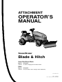
ATTACHMENT
OPERATOR’S
MANUAL
Snow/Dozer
Blade & Hitch
Snow Plow/Dozer Blade
Mfg. No.
1693754
Description
42” Remote Angling Snow Plow/Dozer Blade
Hitch
Mfg. No.
1693755
Description
Hitch (for Express Series & Regent / 500 / 2500 Series)
1721301-02
Rev 1/2001
TP 100-2353-02-AT-SMA
Table of Contents
Recommended Accessories ..............................1
Adjustments.........................................................7
Skid Shoe Adjustment .....................................7
Spring Tension.................................................7
Lift Height Adjustment .....................................7
Downward Pressure Adjustment .....................7
Safety Rules & Information
General Warnings............................................2
Operating on Slopes........................................2
Preparation ......................................................2
Operating Safety..............................................2
Initial Setup & Assembly
Dozer Components..........................................9
Hitch Components .........................................10
Assemble Blade.............................................11
Assemble & Install Hitch................................11
Install Pushbar...............................................13
Install Lift Rod................................................14
Install Angling Control Rod ............................15
Features & Controls ............................................3
General Operating Instructions
Checks Before Starting....................................4
Engine & Ground Speed Selection..................4
Transporting.....................................................4
Starting & Stopping .........................................4
Changing Angle of the Blade...........................5
Dozing Tips......................................................5
Snow Plowing Tips ..........................................5
Attaching & Removing the Hitch & Blade
Removing & Attaching Dozer Blade ..............16
Removing & Attaching Hitch..........................17
Storage .................................................................5
Hardware Identification
& Torque Specifications....................................18
Maintenance & Normal Care Schedule..............6
Schedule for Normal Care ...............................6
Lubricate the Dozer Blade ...............................6
NOTE: In these instructions, “left” and “right” are
referred to as seen from the operating position.
Recommended Accessories
For best performance, it is recommended to use tire chains and two rear wheel weights. A rear-mounted weight
carrier can also be added for additional traction. The maximum weight added to the tractor should not exceed 35
lbs. per wheel, plus 100 additional pounds in the rear weight box.
For operation on slopes greater than 15% (8.5°), Quick Tach Weights, tire chains, and wheel weights are recommended. Never operate on slopes greater than 17.6% (10°).
Required Accessories
A Lift Lever Kit is required for the models covered by this manual, and must be installed as part of hitch installation.
© Copyright 2000 Simplicity Manufacturing, Inc.
All Rights Reserved. Printed in USA.
TP 100-2353-02-AT-SMA
1
Safety Rules
& Information
Read these safety rules and follow them closely. Failure to obey these rules could result in loss of control
of unit, severe personal injury or death to you, or bystanders, or damage to property or equipment.
The triangle
in text signifies important cautions or warnings which must be followed.
PREPARATION
GENERAL WARNINGS
O Disengage the PTO before making any adjustments.
O Never attempt to make any adjustments while engine
is running.
O Thoroughly inspect the area where the dozer is to be
operated and remove all foreign objects.
O Adjust the skid shoe height to clear gravel or crushed
stone surface. See the Adjustments section for procedure.
O Know the tractor controls and how to stop quickly.
READ THE TRACTOR OPERATOR’S MANUAL.
O Read this manual and the tractor Operator’s Manual
carefully. Be thoroughly familiar with the controls and
the proper use of the equipment.
O Never allow children to operate the machine. Do not
allow adults to operate it without proper instruction.
O Do not carry passengers.
O Use only attachments or accessories designed for
your machine. See your dealer for a complete list of
recommended attachments or accessories.
O Keep the area of operation clear of all persons, particularly small children, and pets.
O Never direct discharge towards bystanders.
O Make sure all hardware is secure and that dozer
blade is in good operating condition.
O Check to be sure all safety devices and shields are in
place.
O Check that all adjustments are correct before using
this unit.
O Gasoline is highly flammable. Follow all precautions
listed in your tractor’s operator’s manual.
O Always wear eye protection while operating and performing adjustments to protect eyes from debris
thrown by the dozer.
O When cleaning, repairing, or inspecting the unit make
sure all moving parts have stopped. Disconnect and
secure the spark plug wires and remove the key to
prevent accidental starting.
OPERATING SAFETY
O Always clear snow up and down the face of slopes,
never across the face. Exercise extreme caution
when changing direction on slopes. Do not attempt to
clear steep slopes.
O Exercise extreme caution when operating on, or
crossing, gravel drives, walks or roads. Stay alert for
hidden hazards or traffic.
O After striking an object or if unit starts to vibrate
abnormally, stop the engine and remove the key.
Check for the cause and any damage before restarting. Before any inspection, make sure all moving
parts have stopped.
O Take all possible precautions before leaving operator’s position. Lower the attachment, set the parking
brake, stop the engine and remove the key.
O Never operate near glass enclosures, automobiles,
window wells, dropoffs, etc.
O Do not put hands or feet near or under the dozer
blade. Keep clear of the dozer blade at all times.
O Do not overload machine capacity by attempting to
clear too much material at too fast a rate.
O Never operate unit at high transport speeds on slippery surfaces. Use care when travelling in reverse.
O Never operate the dozer blade without good visibility
or light. Always be sure your feet are properly placed
on the footrests and keep a firm hold on the steering
wheel.
O Do not run the engine indoors.
O Never allow anyone in front of the unit.
DANGER
OPERATING ON SLOPES
CAN BE DANGEROUS
For operation on slopes greater than 15% (8.5°),
weight box, tire chains, and wheel weights are
recommended. NEVER OPERATE ON SLOPES
GREATER THAN 17.6% (10°).
2
Features
& Controls
B
CONTROL FUNCTIONS
A
The information below briefly describes the
function of individual controls. Operating the
tractor and dozer require the combined use of
these controls and additional controls whose
operation is described in the tractor Operator’s
Manual.
Please Take a moment and
familiarize yourself with the
name, location, and function
of these controls so that you
will better understand the safety and operating instructions
provided in this manual.
Figure 1. Control Locations
A. Blade Angle Control Lever
B. Attachment Lift
A. Blade Angle Control Lever
The blade angle release lever controls a spring-loaded
plate which locks the blade in one of three positions.
Use an abrupt pushing/pulling motion to release the
angling mechanism and move the blade left or right.
Push the angling lever forward fully to lock the blade in
the left position. Pull the lever fully back to lock the
blade in the right position. Move the lever slowly past
center to lock in the centered position.
NOTE: It is easier to change the angle of the blade with
the attachment raised.
B. Attachment Lift
TRACTOR CONTROLS
The attachment lift lever raises and lowers the dozer
blade. To RAISE an attachment, depress the release
button on top of the lever and pull back. To LOWER an
attachment, depress the release button and move the
lever forward.
Before you begin operating the tractor with the dozer
blade attachment, make certain you have:
• Read and understood the instructions in the
tractor Operator’s Manual.
• Become thoroughly familiar with all of the
tractor controls and their operation, including
how to safely and properly start and stop the
unit.
The back notch suspends the blade for transporting to
and from the worksite. The middle notch is the “float”
position. The front notch applies downward pressure on
the blade. See the Adjustments section for proper blade
adjustment.
• Practice driving in an open area—without dozing—to become accustomed to the unit.
3
General
Operating Instructions
Checks Before Starting
WARNING
1. Refer to the Maintenance & Adjustments sections of
this manual and perform any needed service. Also,
refer to the tractor Operator’s Manual and perform
any required service.
Perform the Safety System Interlock test found in
your tractor Operator’s Manual. If tractor does not
pass the test, do not operate the tractor. See your
authorized dealer. Under no circumstances
should you attempt to defeat the safety system.
2. Remove any objects from the work area which might
interfere with plowing activity.
Use caution when plowing a snow covered area.
Snow can cover objects such as curbs, drop-offs,
and other obstacles. Be familiar with the area you
are plowing.
3. Adjust the skid shoes to desired height. See Skid
Shoe Adjustment.
4. Make sure all hardware is present and secure.
To prevent an explosion or fire, never store the
tractor with fuel in the tank inside a building
where an ignition source is present.
Engine & Ground Speed Selection
Always run the engine at full throttle.
Set tractor speed to obtain the needed power to move
the material. Operate at a safe speed, depending on
conditions, so that you have complete control of the tractor. Rear wheel weights and chains are recommended
for slippery surfaces.
IMPORTANT NOTE
To prevent damage to the unit, always
raise the dozer blade BEFORE turning or
backing up.
A rear weight carrier is recommended for additional traction.
DANGER
OPERATING ON SLOPES CAN BE DANGEROUS
Transporting
Never operate on slopes greater than 17.6% (10°)
which is a rise of 3-1/2 feet (106cm) vertically in
10 feet (607cm) horizontally.
For maximum ground clearance, transport the blade to
and from work areas fully raised and angled straight
ahead.
Operate the unit at a slow ground speed when
driving onto slope. Avoid using brakes to control
ground speed.
Starting & Stopping
When operating on slopes that are greater than
15 % (8.5°) but less than 17.6%, use additional
wheel weights or counterweights.
1. Start the tractor engine. Set engine throttle to full.
2. Raise the attachment lift and travel to the work site.
3. Set the angling control to the desired angle.
In addition to counterweights, use extra caution
when operating on slopes. Drive UP and DOWN
the slope, never across the face, use caution
when changing directions and DO NOT START
OR STOP ON SLOPE.
4. Lower the attachment lift and begin plowing.
5. Raise the plow before backing up.
6. To stop the tractor, set ground speed to neutral and
set the parking brake. Before leaving the seat, stop
the engine, set the parking brake, remove the key,
and wait for all moving parts to stop.
For additional traction, tire chains and a weight
box can be added. Maximum weight added to
tractor should not exceed 35 lbs. per wheel and
100 additional lbs. in weight box.
4
General Operating Instructions
Changing Angle of the Blade:
Snow Plowing Tips
See Figure 1 for location of Controls.
• Determine the best snow removal pattern before
beginning.
NOTE: It is easier to change the angle of the blade with
the attachment raised.
• Plan the pattern so that you avoid pushing snow onto
cleared areas.
1. Raise the attachment lift.
• When land contour permits, it is best to travel in the
longest direction to minimize turning.
2. Use an abrupt pushing/pulling motion to release the
angling mechanism and move the blade left or right.
Push the angling lever forward fully to lock the blade
in the left position. Pull the lever fully back to lock the
blade in the right position. Move the lever slowly over
center to lock in the centered position.
• In very deep or heavy snow, it may be necessary to
make the first pass with dozer blade partially raised,
then repeat each pass with the blade lowered to clear
the material left on the surface. Also, it may be necessary to clear less than the full width of the dozer
blade or reduce ground speed.
Dozing Tips
• Snow tends to freeze into solid banks when plowed
off a driveway or other large area. Because of this
you may want to plow snow several feet past the
edge of the drive to allow space for future plowing to
build up.
• Determine the best dozing pattern before beginning.
• When land contour permits, it is best to travel in the
longest direction to minimize turning.
• In very deep snow or gravel, it may be necessary to
make the first pass with dozer blade partially raised,
then repeat each pass with the blade lowered to clear
the material left on the surface. Also, it may be necessary to clear less than the full width of the dozer
blade or reduce ground speed.
• If pushing snow past the edges of driveways or sidewalks, be careful not to tear up the grass buried
under snow next to the drive or sidewalk. Lift the
blade several inches off the ground to avoid damaging the grass.
• Spinning tires with tire chains can leave unsightly
marks or permanent damage to asphalt or concrete
driveways or sidewalks. Avoid sudden stops or
starts.
• When dozing, push the dirt to the desired location,
then drag the blade backwards for final leveling. Pack
down the dirt or gravel by driving the tractor over the
leveled area.
• Use any slight grade to your advantage, doze downhill, and set the blade angle so that the plowed material is moving downhill as it leaves the blade.
Storage
Off-Season Storage
IMPORTANT NOTE
1. Remove dozer blade and hitch from the tractor.
Refer to Tractor Operator’s Manual for
important information concerning safely
storing your tractor.
2. Use water pressure or a brush to thoroughly clean
the dozer blade.
3. Paint, or lightly coat with oil, any area where paint
has been worn or chipped away.
Daily Storage
4. Lubricate the dozer blade.
1. Allow tractor engine to cool before storing in any
enclosure.
5. Store the dozer blade and hitch in a dry place.
2. After dozing or plowing jobs are completed, hose or
brush down the blade to remove excess dirt.
3. Lightly oil all pivot points. Coat bare metal surfaces to
prevent corrosion.
5
Maintenance
WARNING
Lubricate Dozer Blade
To avoid serious injury, perform maintenance on
the tractor or dozer blade only when the engine is
stopped, parking brake is set and all moving parts
have stopped. Always remove the ignition key
before beginning maintenance or adjustments to
prevent accidental starting of the engine.
Lubricate the dozer blade as shown in Figure 2. Where
an oil can is shown, wipe the area clean, apply a few
drops of oil (SAE 30), then wipe up drips or spills.
In general, linkage connections and other parts that have
partial rotational or sliding movement should be lubricated periodically with SAE 30 weight oil. Avoid applying
excessive amounts of oil since this may cause a build-up
of dirt around the lubricated area, making subsequent
lubrication more difficult to accomplish.
Schedule For Normal Care
Care Required
Schedule
Clean debris from
dozer blade.
Lubricate dozer blade.
After each use.
Every 10 hours or at
least once a year.
Figure 2. Lubrication Points
6
Adjustments
Skid Shoe Adjustment
Slotted holes are provided to permit adjustment of the
shoe assemblies for raising and lowering the blade to
various working heights (see Figure 3).
When cleaning snow from gravel or earth drives or
walks, the shoe assemblies should be lowered fully to
prevent blade contact with gravel or ground. When
cleaning smooth hard surfaces like concrete, the shoe
assemblies are normally placed fully up to allow the
blade to scrape the surface.
To adjust the skid, raise the blade off the ground and
block with a piece of wood. Loosen the bolts (B, Figure
3) and move the skid shoes (A) up or down to desired
height. Tighten the bolts securely.
Figure 3.
A. Skid Shoes
B. Bolts
Spring Tension
See Figure 4. This snow plow/dozer blade is spring
loaded so that when the blade strikes a solid object, the
springs will allow the blade to release as shown, rather
than cause damage. The blade will go back to its original
position after object is cleared.
Figure 4. Dozer Blade “Released”
See Figure 5. To adjust spring tension hold rear nut (B)
and loosen front nut (E). Tighten rear nut (B) to increase
spring tension, or loosen to decrease tension.
For initial adjustment, tighten nut (B) on each eyebolt
enough to expose about 3/4" (19mm) of thread. Tighten
front nut (E) against rear nut (B) to lock adjustment in
place.
Figure 5. Tension Springs
A. Eyebolt
B. Nut, 5/16
C. Spring
7
D. Pivot Frame
E. Nut, 5/16
Adjustments
Lift Rod Adjustment
B
The lift lever can be placed in one of three notches and
is held in position by the lever latch. (see Figure 7).
When the lever latch is placed in notch 1 the lift lever
should be applying downward pressure on the attachment. In position 2, the “float” position, the attachment
should experience negligible upward or downward pressure. Position 3 should raise the attachment approximately 6“ above the ground.
A
C
D
E
NOTE: Always adjust the lift height before and after
adjusting the downward pressure.
LIFT HEIGHT ADJUSTMENT
1. Place the lever latch in notch 3 (see Figure 7). The
snowthrower should be approximately 6” off the
ground. If not, go to step 2.
Figure 6. Adjusting Lift Rod
A. Front Set Collar
B. Rod Guide
C. Spring
D. Rear Set Collar
E. Spring Clip
2. Lower the attachment and adjust the front set collar
(A, Figure 7) to achieve the correct lift height.
DOWNWARD PRESSURE ADJUSTMENT
IMPORTANT NOTE
Notch 2
DO NOT OVER-COMPRESS THE SPRINGS.
In addition to providing downward pressure,
the springs are an elastic medium that
absorbs shocks caused by bumps and
cracks in ground surfaces. Over-compressing the springs defeats this and may cause
damage to the unit.
Notch 1
Notch 3
1. Move the lever latch from notch 2 to notch 1 (See
Figure 7).
2. The spring (C, Figure 6) should be slightly compressed applying downward pressure to the
snowthrower. If not, adjust the rear set collar (D,
Figure 6) to achieve the desired amount of downward
force. Do not over-compress the lift rod spring.
Figure 7. Lift Lever Quadrant - Side View
8
Initial Setup
& Assembly
Packaged with Hitch
1
4
5
31
4
6
32
3
4
33
30
2
4
3
7
8
34
9
10
35
36
29
39
28
37
36
11
12
27
2
26
25
38
22
24
23
Control Rod Guide
Used with Snowcabs
10
34 41
21
20
17
18
40
42
19
16
34
43
13
Figure 8.
Ref Qty
1
1
2
6
3
2
4
4
5
2
6
1
7
1
8
1
9
1
10
3
11
1
12
1
13
1
14
6
15
10
16
6
17
2
18
4
19
4
20
2
21
2
22
1
14
15
Description
ROD, Control Handle, Upper
NUT, Hex, 5/16-18
LOCKWASHER, 5/16
WASHER, 5/16
CAPSCREW, 5/16-18 x 1-1/4
ROD, Control Handle, Lower
CLEVIS
WASHER, 1/2
CLIP, Hair Pin
COTTER PIN
ROD & PLATE ASMY, Pivot
DOZER BLADE ASMY, 42”
SCRAPER BAR
CARRIAGE BOLT, 3/8-16 x 1
LOCKWASHER, 3/8
NUT, Hex, 3/8-16
SKID SHOE
WASHER, Plain, 3/8
CAPSCREW, 3/8-16 x 3/4
CAPSCREW, 1/2-13 x 1-1/2
SPACER, 1/2 ID x 3/4 OD x 5/16 LG
ROD, Latch Stop
16
Ref Qty
23
2
24
1
25
2
26
2
27
1
28
1
29
2
30
1
31
1
32
1
33
2
34
4
35
2
36
2
37
1
38
1
39
2
40
1
41
1
42
1
43
1
9
Description
LOCKNUT, 1/2-13
FRAME ASMY, Dozer
EYEBOLT
SPRING, Extension
CLIP, Hair Pin
PLATE ASMY, Latch
SPRING, Torsion
EYEBOLT, 1/4-20 x 1-1/2
LOCKNUT, Nylock, 1/4-20
BRACKET, Control Rod
CARRIAGE BOLT, 5/16-18 x 1-1/4
WASHER, 5/16
LOCKNUT, Center, 5/16-18
PIN, Clevis
PIN, Clevis
CLIP, Hair Pin
CLIP, Safety
CAPSCREW, 5/16-18 x 1-1/2
BRACKET, Control Rod
NUT, Hex, Full, 5/16
LOCKWASHER, 5/16
Components
C
F
B
C
D
D
E
M
A
L
J
K
F
Q
P
I
N
O
G
F
H
G
Q
Figure 9. Hitch Assembly
A.
B.
C.
D.
E.
F.
G.
H.
I.
Hitch Assy.
Rear Support Assy.
Washers (Qty. 2)
Hairpin Clip (Qty. 2)
Pin
Safety Clip (Qty. 4)
Clevis Pin, 3/8 (Qty. 2)
Rod
Spring Assist Bracket
J.
K.
L.
M.
N.
O.
P.
Q.
10
Capscrew, 3/8-16 x 2
Spacer, 25/64 x 5/8 x 17/64
Spacer, 13/32 x 1 x 13/16
Nut, Whizlock, 3/8-16
Lockwasher, 1/2
Hex Nut, 1/2-13
Capscrew, 1/2-13 x 1-1/4
Upstop (Qty. 2)
Initial Setup & Assembly
Figure 10. Bar Stop
A. Bar Stop
B. Taptite Screw, 5/16-18 x 1
Figure 11. Tension Springs
A. Eyebolt
D. Pivot Frame
B. Nut, 5/16
E. Nut, 5/16
C. Spring
INITIAL SETUP & ASSEMBLY
NOTE: Some of the following setup procedures may
already be completed.
Assemble Blade
E
1. Place the blade on a flat surface.
2. See Figure 10. Install one bar stop (A) using the two
5/16-18 x 1 taptite screws (B). Do not install second
bar stop.
A
3. See Figure 11. Insert threaded end of eyebolt (A)
through lug on blade, and screw on 5/16 nut (B) just
far enough so that it is flush with the end of the eyebolt.
4. See Figure 11. Hook the springs (C) into the pivot
frame (D). Using a pliers, stretch the springs to hook
the opposite ends to the eyebolts (A).
B
D
C
5. See Figure 11. Tighten the nut (B) on each eyebolt
enough to expose about 3/4" (19 mm) of thread.
Figure 12. Spring Assist Bracket
A. Spring Assist Bracket
B. Capscrew, 1/2-13 x 1-1/4
C. Lockwasher, 1/2
D. Hex Nut, 1/2-13
E. Hitch
6. See Figure 11. Holding the first nut (B) with a
wrench,add a second nut (E) to each eyebolt, and
tighten securely against the first nut to act as a jam
nut.
Assemble & Install Hitch
1. See Figure 12. Assemble the spring-assist bracket
(A) to the hitch assembly (E). Secure with capscrew,
lockwasher, and nut.
11
Initial Setup & Assembly
2. Increase front tire pressure to 20 psi (138 kPa) to
compensate for added weight of the hitch, plus bar
and blade. Be sure both tires have equal pressure.
A
3. From the front of tractor, slide the hitch under the
tractor so that the hitch bar is positioned at the front of
the unit.
C
4. See Figure 13. Turn the wheels fully left and lift the
front hitch bar (A) up onto the tractor brackets (D).
Make sure it is fully seated into the tractor brackets.
Install the long hitch pin (B) through the bracket (bottom rear holes) and up-stop brackets (E). Secure it
with the safety clip (C).
E
B
D
NOTE: If your tractor is not equipped with the Large Lift
Lever, install it at this time. Follow the instructions supplied with the kit.
Figure 13. Installing Hitch to Front of Tractor
A. Hitch Bar
D. Tractor Brackets
B. Hitch Pin
E. Up-Stop Brackets
C. Safety Clip
Note that the rear bracket (A, Figure 14) is mounted
using the lift lever rod (B). After installation, the lift lever
rod assy. can be removed by pivoting the lift lever fully
forward until it is parallel to the ground, and sliding it out
of the quadrant
5. See Figure 14. Slide the rear bracket (A), and washers (D), onto the lift lever shaft, and secure with the
hairpin clips (C).
K
C
6. See Figure 14. Position the rear plate of the hitch
assembly between the hanger tabs on the rear bracket, and secure at the top mounting hole using the clevis pin (F), and hairpin clip (K).
B
J
A
D
F
7. See Figure 14. Install the capscrew (G), spacers (H &
I), and whizlock nut (J) in the lower mounting hole as
shown, and tighten securely.
I
H
G
E
8. The hitch assembly is now assembled to the unit, and
you may proceed to installation of the push bar and
blade.
Figure 14. Installing Hitch to Rear Bracket
A. Rear Bracket
G. Capscrew, 3/8-16 x 2
B. Lift Lever Rod H. Spacer, 25/64 x 5/8 x 17/64
C. Hairpin Clip
I. Spacer, 13/32 x 1 x 13/16
D. Washer
J. Nut, Whizlock, 3/8-16
E. Hitch
K. Hairpin Clip
F. Clevis Pin
12
Initial Setup & Assembly
Install Push Bar
C
1. Drive the tractor over the push bar until the rear of the
push bar is positioned between the side rail extensions on the front of the hitch.
2. Stop engine, remove key and set parking brake.
3. See Figure 15. Align the mounting holes in the rear
corners of the push bar (A) with the mounting holes in
the hitch (B), and secure the push bar to the hitch
with a clevis pin (C), and safety clip (D) at each corner.
D
B
A
Figure 15.
A. Push Bar
B. Hitch
C. Clevis Pin
D. Safety Clip
(Not shown)
4. See Figure 16. Insert front of push bar (A) into pivot
frame (B) on rear of blade. Then install the pivot pin
(C) down thru front holes in hitch and pivot frame.
Secure with spring clip (D).
Figure 16. Dozer Blade Assembled and Installed
A. Push Bar
C. Pivot Pin
B. Pivot Frame
D. Spring Clip
13
Initial Setup & Assembly
D
C
B
C
B
A
A
Figure 17. Lift Rod Assembly
A. Set Collars
C. Spring
B. Rod Guide
D. Lift Rod
Figure 19. Installing Lift Rod to Manual Lift Lever
A. Lift Rod
C. Spring Clip
B. Manual Lift Lever
C
B
A
E
A
Figure 18. Lift Rod Installation
A. Rod Guide
C. Spring Clip
B. Push Bar
C
D
B
Figure 20. Install Lift Assist Chain
A. Clevis Pin
D. Safety Clip
B. Spring
E. 5/16 Washers
C. Chain
Install Lift Rod
4. Raise the dozer using the lift lever. Support the
weight of the blade using wood blocks. Install the lift
assist spring as shown in Figure 20.
1. Assemble lift rod as shown in Figure17.
2. See Figure 18. Insert the rod guide (A) through the
hole in the push bar (B), and secure with spring clip
(C).
3. See Figure 19. Connect rear of lift rod (A) to manual
lift lever (B), and secure with spring clip (C).
5. Perform lift rod adjustment (see Adjustments section).
14
Initial Setup & Assembly
B
A
C
A
B
Figure 21. Underside of Left Footrest.
A. Carriage Bolt, Lockwasher, & Nut
B. Pedal Plate
Figure 22. Control Rod Support
A. Support
B. 5/16-18 x 1-1/4 Carriage Bolts
C. 5/16 Lockwashers & Nuts
Install Angling Control Rod
NOTE: If installing the dozer attachment on a unit
equipped with a snowcab, replace the control rod support (A, Figure 22) with the hanging support (Ref. No. 41,
Figure 8). Mount the hanging support to the front cab
cross-bar.
D
C
B
E
1. Remove and discard the two rear nuts, lockwashers,
and carriage bolts (A, Figure 21) securing the back of
the foot pedal plate (B).
F
2. Using the foot pedal plate (B) as a guide, drill two
5/16” holes up through the foot pedal pad.
3. Set the angling control support (A, Figure 22) on the
foot rest pad. Insert two 5/16-18 x 1-1/4 carriage
bolts (B) through the support, footrest pad, footrest,
and foot pedal plate. Secure using new lockwashers
and nuts (C).
G
4. Connect the lower angling rod (F, Figure 23) to the
dozer release lever using a hair pin clip and washer
(G).
5. Insert the upper control rod (C) through the eyelet
(B), and secure the eyelet to the support using a 1/420 nylock nut (A).
Figure 23. Assemble Control Rods
A. 1/4-20 Nylock Nut
B. Eyelet
C. Upper Control Rod
D. 5/16-18 x 1-1/4 Capscrew
E. 5/16 Washers, Lockwashers, & Nuts
F. Lower Control Rod
G. Hair Pin Clip & Washer
NOTE: It may be necessary to leave the eyelet nut (A,
Figure 23) loose to prevent binding.
6 Secure the upper rod (C) to the lower rod (F) using
two 5/16-18 x 1-1/4 capscrews (D), washers (qty. 4),
lockwashers, and nuts (E). NOTE: Match offset to
offset so the rods form a straight line.
15
A
Removing &
Attaching the Hitch & Blade
A
B
B
C
D
F
E
F
Figure 24. Dozer Removal
A. Support Arm
C. Pivot Pin
B. Hair Pin Clip
D. Hair Pin Clip & Washer
E. Clevis Pin
F. Clevis Pins
REMOVAL & INSTALLATION
Removing & Attaching Dozer Blade
1. Lower the blade. Put the lift lever in the middle notch
(float position).
5. Raise the push bar and remove pin (E) securing the
chain to the hitch bracket.
2. Remove the hair pin clip and washer (D, Figure 24)
securing the angling control rod to the clevis.
Disconnect the angling control rod.
6. Lower the lift and remove the pins (B) securing the lift
rod to the push bar and lift rod.
7. Remove the pins (F) securing the push bar to the
tractor hitch.
3. Remove the angling control rod from the
support arm (A).
8. Reinstall all pins for storage.
4. Remove the pivot pin (C) connecting the blade and
pushbar. Remove the blade.
Install in reverse order of removal.
16
Removing & Attaching
1
K
C
B
J
A
D
F
I
H
G
2
E
3
Figure 25. Installing Hitch to Rear Bracket
A. Rear Bracket
G. Capscrew, 3/8-16 x 2
B. Lift Lever Rod H. Spacer, 25/64 x 5/8 x 17/64
C. Hairpin Clip
I. Spacer, 13/32 x 1 x 13/16
D. Washer
J. Nut, Whizlock, 3/8-16
E. Hitch
K. Hairpin Clip
F. Clevis Pin
A
Figure 26. Lift Lever Removal
A. Capscrew Location (Remove)
Removing & Attaching Hitch
1. Remove the safety clip (K, Figure 25).
A
2. Remove the spring clips (C) securing the rear hitch
bracket (A) to the lift lever rod (B).
3. See Figure 26. Remove the caspcrew from location
(A). Depress the lift lever release button and rotate
the lever forward until the lever latch clears the
mounting bracket. Slide the lever and rod assembly
out of the hitch bracket and mounting bracket.
C
E
D
B
4. See Figure 27. Remove the safety clip (C) and long
hitch pin (B) from the front of the hitch. Remove the
hitch from the front tractor brackets.
Install in reverse order of removal.
Figure 27. Installing Hitch to Front of Tractor
A. Hitch Bar
D. Tractor Brackets
B. Hitch Pin
E. Up-Stop Brackets
C. Safety Clip
17
Hardware Identification & Torque Specifications
Common Hardware Types
Torque Specification Chart
Hex Head Capscrew
FOR STANDARD MACHINE HARDWARE (Tolerance ± 20%)
Washer
Hardware
Grade
Lockwasher
Carriage Bolt
No
Marks
SAE Grade 2
Hex Nut
Size Of
Hardware
Standard Hardware Sizing
8-32
8-36
10-24
10-32
1/4-20
1/4-28
5/16-18
5/16-24
3/8-16
3/8-24
7/16-14
7/16-20
1/2-13
1/2-20
9/16-12
9/16-18
5/8-11
5/8-18
3/4-10
3/4-16
7/8-9
7/8-14
1-8
1-12
When a washer or nut is identified as 1/2”, this is the
Nominal size, meaning the inside diameter is 1/2 inch; if a
second number is present it represent the threads per inch
When bolt or capscrew is identified as 1/2 - 16 x 2”, this
means the Nominal size, or body diameter is 1/2 inch; the
second number represents the threads per inch (16 in this
example, and the final number is the body length of the
bolt or screw (in this example 2 inches long).
The guides and ruler furnished below are designed to
help you select the appropriate hardware and tools.
0
1/4
Nut, 1/2”
1/2
Inside
Diameter
3/4
1
1/4
1/2
3/4
Screw, 1/2 x 2
2
1/4
Body
Diameter
in/lbs
ft/lbs
19
20
27
31
66
76
11
12
20
23
30
35
50
55
65
75
90
100
160
180
140
155
220
240
Nm.
2.1
2.3
3.1
3.5
7.6
8.6
15.0
16.3
27.2
31.3
40.8
47.6
68.0
74.8
88.4
102.0
122.4
136
217.6
244.8
190.4
210.8
299.2
326.4
SAE Grade 5
in/lbs
ft/lbs
30
31
43
49
8
10
17
19
30
35
50
55
75
90
110
120
150
180
260
300
400
440
580
640
SAE Grade 8
Nm.
in/lbs
ft/lbs
Nm.
3.4
3.5
4.9
5.5
10.9
13.6
23.1
25.8
40.8
47.6
68.0
74.8
102.0
122.4
149.6
163.2
204.0
244.8
353.6
408.0
544.0
598.4
788.8
870.4
41
43
60
68
12
14
25
27
45
50
70
80
110
120
150
170
220
240
386
420
600
660
900
1,000
4.6
4.9
6.8
7.7
16.3
19.0
34.0
34.0
61.2
68.0
95.2
108.8
149.6
163.2
204.0
231.2
299.2
326.4
525.0
571.2
816.0
897.6
1,244.0
1,360.0
NOTES
1. These torque values are to be used for all hardware
excluding: locknuts, self-tapping screws, thread forming
screws, sheet metal screws and socket head setscrews.
2. Recommended seating torque values for locknuts:
a. for prevailing torque locknuts - use 65% of grade 5
torques.
b. for flange whizlock nuts and screws - use 135% of
grade 5 torques.
3. Unless otherwise noted on assembly drawings, all torque
values must meet this specification.
1/2
Body
Length
3/4
3
1/4
1/2
3/4
4
Wrench & Fastener Size Guide
1/4
5/16
3/8
1/4” Bolt or Nut
Wrench—7/16”
5/16” Bolt or Nut
Wrench—1/2”
3/8” Bolt or Nut
Wrench—9/16”
7/16
DIA.
7/16” Bolt or Nut
Wrench (Bolt)—5/8”
Wrench (Nut)—11/16”
1/2
DIA.
1/2” Bolt or Nut
Wrench—3/4”
Simplicity Mfg. Inc.
500 N Spring Street / PO Box 997
Port Washington, WI 53074-0997 USA
© Copyright 2000 Simplicity Manufacturing, Inc.
All Rights Reserved. Printed in USA.