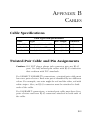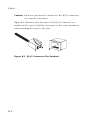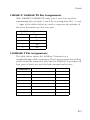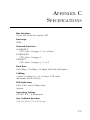
1
EZ Card1000
1000 Mbps Gigabit Ethernet
PCI Network Card
◆
◆
◆
◆
◆
High performance for instant access to network
resources
1000BASE-T model for Category 5 UTP
Supports PCI 32 and 64-bit bus-master architectures
Full-duplex operation for up to 2 Gbps of bandwidth
IP, TCP and UDP checksum off-loading capability
reduces CPU overhead
User Guide
SMC9462TX
EZ Card 1000
User Guide
From SMC’s EZ line of feature-rich workgroup LAN solutions
6 Hughes
Irvine, CA 92618
Phone: (949) 707-2400
March 2001
Pub. # 150416-102 R01
Information furnished by SMC Networks, Inc. (SMC) is believed to
be accurate and reliable. However, no responsibility is assumed by
SMC for its use, nor for any infringements of patents or other rights
of third parties which may result from its use. No license is granted
by implication or otherwise under any patent or patent rights of
SMC. SMC reserves the right to change specifications at any time
without notice.
Copyright © 2001 by
SMC Networks, Inc.
6 Hughes
Irvine, CA 92618
All rights reserved. Printed in Taiwan
Trademarks:
SMC is a registered trademark; and EZ Card, EtherPower and SuperDisk are trademarks of SMC
Networks, Inc. Other product and company names are trademarks or registered trademarks of
their respective holders.
LIMITED WARRANTY
Limited Warranty
Limited Warranty Statement: SMC Networks, Inc. (“SMC”) warrants its products to
be free from defects in workmanship and materials, under normal use and service,
for the applicable warranty term. All SMC products carry a standard 90-day limited
warranty from the date of purchase from SMC or its Authorized Reseller. SMC may,
at its own discretion, repair or replace any product not operating as warranted with
a similar or functionally equivalent product, during the applicable warranty term.
SMC will endeavor to repair or replace any product returned under warranty within
30 days of receipt of the product.
The standard limited warranty can be upgraded to a Limited Lifetime* warranty by
registering new products within 30 days of purchase from SMC or its Authorized
Reseller. Registration can be accomplished via the enclosed product registration
card or online via the SMC web site. Failure to register will not affect the standard
limited warranty. The Limited Lifetime warranty covers a product during the Life of
that Product, which is defined as the period of time during which the product is an
‘Active’ SMC product. A product is considered to be ‘Active’ while it is listed on the
current SMC price list. As new technologies emerge, older technologies become
obsolete and SMC will, at its discretion, replace an older product in its product line
with one that incorporates these newer technologies. At that point, the obsolete
product is discontinued and is no longer an ‘Active’ SMC product. A list of
discontinued products with their respective dates of discontinuance can be found at
http://www.smc.com/smc/pages_html/support.html.
All products that are replaced become the property of SMC. Replacement products
may be either new or reconditioned. Any replaced or repaired product carries
either a 30-day limited warranty or the remainder of the initial warranty, whichever
is longer. SMC is not responsible for any custom software or firmware,
configuration information, or memory data of Customer contained in, stored on, or
integrated with any products returned to SMC pursuant to any warranty. Products
returned to SMC should have any customer-installed accessory or add-on
components, such as expansion modules, removed prior to returning the product
for replacement. SMC is not responsible for these items if they are returned with the
product.
Customers must contact SMC for a Return Material Authorization number prior to
returning any product to SMC. Proof of purchase may be required. Any product
returned to SMC without a valid Return Material Authorization (RMA) number
clearly marked on the outside of the package will be returned to customer at
customer’s expense. For warranty claims within North America, please call our
toll-free customer support number at (800) 762-4968. Customers are responsible for
all shipping charges from their facility to SMC. SMC is responsible for return
shipping charges from SMC to customer.
WARRANTIES EXCLUSIVE: IF AN SMC PRODUCT DOES NOT OPERATE AS
WARRANTED ABOVE, CUSTOMER'S SOLE REMEDY SHALL BE REPAIR OR
REPLACEMENT OF THE PRODUCT IN QUESTION, AT SMC'S OPTION. THE
FOREGOING WARRANTIES AND REMEDIES ARE EXCLUSIVE AND ARE IN LIEU
OF ALL OTHER WARRANTIES OR CONDITIONS, EXPRESS OR IMPLIED, EITHER
LIMITED WARRANTY
IN FACT OR BY OPERATION OF LAW, STATUTORY OR OTHERWISE, INCLUDING
WARRANTIES OR CONDITIONS OF MERCHANTABILITY AND FITNESS FOR A
PARTICULAR PURPOSE. SMC NEITHER ASSUMES NOR AUTHORIZES ANY OTHER
PERSON TO ASSUME FOR IT ANY OTHER LIABILITY IN CONNECTION WITH
THE SALE, INSTALLATION, MAINTENANCE OR USE OF ITS PRODUCTS. SMC
SHALL NOT BE LIABLE UNDER THIS WARRANTY IF ITS TESTING AND
EXAMINATION DISCLOSE THE ALLEGED DEFECT IN THE PRODUCT DOES NOT
EXIST OR WAS CAUSED BY CUSTOMER’S OR ANY THIRD PERSON’S MISUSE,
NEGLECT, IMPROPER INSTALLATION OR TESTING, UNAUTHORIZED ATTEMPTS
TO REPAIR, OR ANY OTHER CAUSE BEYOND THE RANGE OF THE INTENDED
USE, OR BY ACCIDENT, FIRE, LIGHTNING, OR OTHER HAZARD.
LIMITATION OF LIABILITY: IN NO EVENT, WHETHER BASED IN CONTRACT OR
TORT (INCLUDING NEGLIGENCE), SHALL SMC BE LIABLE FOR INCIDENTAL,
CONSEQUENTIAL, INDIRECT, SPECIAL, OR PUNITIVE DAMAGES OF ANY KIND,
OR FOR LOSS OF REVENUE, LOSS OF BUSINESS, OR OTHER FINANCIAL LOSS
ARISING OUT OF OR IN CONNECTION WITH THE SALE, INSTALLATION,
MAINTENANCE, USE, PERFORMANCE, FAILURE, OR INTERRUPTION OF ITS
PRODUCTS, EVEN IF SMC OR ITS AUTHORIZED RESELLER HAS BEEN ADVISED
OF THE POSSIBILITY OF SUCH DAMAGES.
SOME STATES DO NOT ALLOW THE EXCLUSION OF IMPLIED WARRANTIES OR
THE LIMITATION OF INCIDENTAL OR CONSEQUENTIAL DAMAGES FOR
CONSUMER PRODUCTS, SO THE ABOVE LIMITATIONS AND EXCLUSIONS MAY
NOT APPLY TO YOU. THIS WARRAN’Y GIVES YOU SPECIFIC LEGAL RIGHTS,
WHICH MAY VARY FROM STATE TO STATE. NOTHING IN THIS WARRANTY
SHALL BE TAKEN TO AFFECT YOUR STATUTORY RIGHTS.
* SMC will provide warranty service for one year following discontinuance from the
active SMC price list. Under the limited lifetime warranty, internal and external
power supplies, fans, and cables are covered by a standard one-year warranty from
date of purchase.
SMC Networks, Inc.
SMC Networks, Inc.
6 Hughes
Irvine, CA 92618
COMPLIANCES
FCC - Class B
This equipment has been tested and found to comply with the limits for a Class B digital
device, pursuant to Part 15 of the FCC Rules. These limits are designed to provide reasonable protection against harmful interference in a residential installation. This equipment generates, uses and can radiate radio frequency energy and, if not installed and
used in accordance with instructions, may cause harmful interference to radio communications. However, there is no guarantee that the interference will not occur in a particular installation. If this equipment does cause harmful interference to radio or television
reception, which can be determined by turning the equipment off and on, the user is
encouraged to try to correct the interference by one or more of the following measures:
• Reorient the receiving antenna
• Increase the separation between the equipment and receiver
• Connect the equipment into an outlet on a circuit different from that to which the
receiver is connected
• Consult the dealer or an experienced radio/TV technician for help
EC Conformance Declaration - Class B
SMC contact for these products in Europe is:
SMC Networks Europe,
Edificio Conata II,
Calle Fructuós Gelabert 6-8, 2o, 4a,
08970 - Sant Joan Despí,
Barcelona, Spain.
This information technology equipment complies with the requirements of the Low
Voltage Directive 73/23/EEC and the EMC Directive 89/336/EEC, and carries the CE
Mark accordingly. It conforms to the following specifications:
EMC:
EN55022 (1988)/CISPR-22 (1995)
IEC 1000-4-2
IEC 1000-4-3 (1995)
IEC 1000-4-4 (1995)
IEC 1000-4-6 (1995)
Class B
4 kV CD, 8 kV AD
3 V/m
1.0 kV - (power line)
0.5 kV - (signal line)
3 Vrms
i
COMPLIANCES
Industry Canada - Class B
This digital apparatus does not exceed the Class B limits for radio noise emissions from
digital apparatus as set out in the interference-causing equipment standard entitled
“Digital Apparatus,” ICES-003 of the Department of Communications.
Cet appareil numérique respecte les limites de bruits radioélectriques applicables aux
appareils numériques de Classe B prescrites dans la norme sur le matériel brouilleur:
“Appareils Numériques,” NMB-003 édictée par le ministère des Communications.
Japan VCCI Class B
Australia AS/NZS 3548 (1995) - Class B
SMC contact for products in Australia is:
SMC Communications Pty. Ltd.
Suite 18, 12 Tryon Road,
Lindfield NSW2070,
Phone: 61-2-94160437
Fax: 61-2-94160474
ii
TABLE
1
OF
CONTENTS
Installing The Network Card . . . . . . . . . . . . . . . 1-1
Introduction . . . . . . . . . . . . . . . . . . . . . . . . . . .
Hardware Description . . . . . . . . . . . . . . . . . . . .
LED Indicators . . . . . . . . . . . . . . . . . . . . .
Package Contents . . . . . . . . . . . . . . . . . . .
SuperDisk Contents . . . . . . . . . . . . . . . . . . . . . .
System Requirements . . . . . . . . . . . . . . . . . . . . .
Inserting the Network Card . . . . . . . . . . . . . . . .
PCI Configuration . . . . . . . . . . . . . . . . . . . . . . .
Connecting Category 5 Cable . . . . . . . . . . . . . . .
Cable Testing for Existing Category 5 Cable
Adjusting Existing Category 5 Cabling
to Run 1000BASE-T . . . . . . . . . . . . .
Connecting UTP Cable . . . . . . . . . . . . . . .
2
.
.
.
.
.
.
.
.
.
.
.
.
.
.
.
.
.
.
.
.
.
.
.
.
.
.
.
.
.
.
.
.
.
.
.
.
.
.
.
.
.
.
.
.
.
.
.
.
.
.
.
.
.
.
.
.
.
.
.
.
.
.
.
.
.
.
.
.
.
.
.
.
.
.
.
.
.
.
.
.
. 1-1
. 1-2
. 1-3
. 1-4
. 1-4
. 1-5
. 1-5
. 1-7
. 1-8
. 1-8
. . . . . . . . . . 1-8
. . . . . . . . . . 1-9
Installing and Configuring Network Drivers . . 2-1
Windows NT 4.0 Installation . . . . . . . . . .
First-Time Installation . . . . . . . . . . .
Secondary Installation . . . . . . . . . . .
Further Configuration . . . . . . . . . . .
Windows 2000 Installation . . . . . . . . . . . .
Novell NetWare Installation . . . . . . . . . . .
NetWare Server 5.0 . . . . . . . . . . . . .
NetWare Server 4.11 . . . . . . . . . . . .
Linux 2.2.X or Later Installation . . . . . . . .
Manual Loading and Configuration .
Automatic Installation . . . . . . . . . . .
Windows 98 Installation . . . . . . . . . . . . . .
Other Installations . . . . . . . . . . . . . . . . . .
Latest Drivers . . . . . . . . . . . . . . . . . . . . .
3
.
.
.
.
.
.
.
.
.
.
...
...
...
...
...
...
...
...
...
...
...
...
...
...
....
....
....
....
....
....
....
....
....
....
....
....
....
....
...
...
...
...
...
...
...
...
...
...
...
...
...
...
...
...
...
...
...
...
...
...
...
...
...
...
...
...
. . 2-1
. . 2-1
. . 2-3
. . 2-4
. . 2-5
. . 2-6
. . 2-6
. . 2-8
. 2-10
. 2-10
. 2-12
. 2-14
. 2-16
. 2-16
Configuring and Testing the Network Card . . . 3-1
Configuration . . . . . . . . . . . . . . . . . . . . . . . . . . . . . . . . . . . . 3-1
Network Card Information . . . . . . . . . . . . . . . . . . . . . . 3-1
Auto-Negotiation . . . . . . . . . . . . . . . . . . . . . . . . . . 3-1
iii
Network Type . . . . .
Network Address . . .
Jumbo Frame Size . .
IEEE Compliance. . .
Receive Buffer . . . . .
Transmit Buffer . . . .
A
....
....
....
....
....
....
...
...
...
...
...
...
...
...
...
...
...
...
.
.
.
.
.
.
.
.
.
.
.
.
.
.
.
.
.
.
.
.
.
.
.
.
.
.
.
.
.
.
.
.
.
.
.
.
.
.
.
.
.
.
.
.
.
.
.
.
.
.
.
.
.
.
.
.
.
.
.
.
.
.
.
.
.
.
.
.
.
.
.
.
.
.
.
.
.
.
3-2
3-2
3-2
3-2
3-3
3-3
.
.
.
.
.
.
.
.
.
.
.
.
.
.
.
.
.
.
.
.
.
.
.
.
.
.
.
.
.
.
.
.
.
.
.
.
.
.
.
.
.
.
.
.
.
.
.
.
A-1
A-3
A-3
A-4
Cables . . . . . . . . . . . . . . . . . . . . . . . . . . . . . . . . . .B-1
Cable Specifications . . . . . . . . . . . . . . . . . . .
Twisted-Pair Cable and Pin Assignments . . . .
10BASE-T/100BASE-TX Pin Assignments
1000BASE-T Pin Assignments . . . . . . . .
C
.
.
.
.
.
.
Troubleshooting . . . . . . . . . . . . . . . . . . . . . . . . . .A-1
PCI Compatibility . . . . . . . . . . . . . . . . . .
Solutions for Common Problems . . . . . . .
Network Card Installation Problems
Network Connection Problems . . . .
B
.
.
.
.
.
.
.
.
.
.
.
.
.
.
.
.
.
.
.
.
.
.
.
.
.
.
.
.
.
.
.
.
.
.
.
.
.
.
.
.
.
.
.
.
.
.
.
.
.
.
.
.
.
.
B-1
B-1
B-3
B-3
Specifications . . . . . . . . . . . . . . . . . . . . . . . . . . . .C-1
Software Drivers . . . . . . . . . . . . . . . . . . . . . . . . . . . . . . . . . . C-3
Index
iv
CHAPTER 1
INSTALLING THE NETWORK CARD
Introduction
SMC’s EZ Card 1000 network interface card is a Gigabit Ethernet
card for 32 and 64-bit PCI local bus compliant computers. It
operates under the 1000BASE-T specification over Category 5 UTP
Cable. This adapter provides up to ten times the bandwidth of Fast
Ethernet. A true plug-and-play device, this card is auto-configurable
upon power up. Leading-edge ASIC technology and
performance-enhancing techniques maximize throughput and
minimize CPU utilization. The result is a network card that delivers
the performance and reliability demanded by today’s high-end
servers and workstations.
1-1
INSTALLING THE NETWORK CARD
Hardware Description
The EZ Card 1000 is a Gigabit Ethernet network card designed for
32 and 64-bit PCI-bus computers. The SMC9462TX has a single
RJ-45 connector to attach to Category 5 UTP cable and supports
10 Mbps, 100 Mbps and 1000 Mbps Ethernet operations. It also
supports full and half duplex and features auto-negotiation.
Figure 1-1. The EZ Card 1000 SMC9462TX
1-2
INSTALLING THE NETWORK CARD
LED Indicators
The EZ Card 1000 network card includes status LED indicators as
described in the following figure and table.
Figure 1-2. Status LEDs
LED
Status
Description
Link
On Green
Indicates a valid 1000BASE-T
connection on the fiber port.
ACT
Flashing
Green
Indicates that the adapter is
transmitting or receiving data.
1000
On Green
Indicates that the adapter is
operating at 1000 Mbps.
100
On Green
Indicates that the adapter is
operating at 100 Mbps.
10
On Green
Indicates that the adapter is
operating at 10 Mbps.
1-3
INSTALLING THE NETWORK CARD
Package Contents
After unpacking the EZ Card 1000, check the contents of the box to
be sure you have received the following components:
◆
EZ Card 1000 network card SMC9462TX
◆
SuperDisk™ network drivers diskette
◆
This User Guide
◆
SMC Warranty Registration Card
Immediately inform your dealer in the event of any incorrect,
missing or damaged parts. If possible, please retain the carton and
original packing materials in case there is a need to return the
product.
Please fill out and return the Warranty Registration Card to SMC or
register on SMC’s Web site. The EZ Card 1000 is covered by a
limited lifetime warranty.
SuperDisk Contents
The SuperDisk contains drivers and other files to make network
card configuration, testing, and driver installation easy.
1-4
◆
RELEASE.TXT—a summary of the contents of the driver
diskette.
◆
README.TXT—contains basic information and instructions for
installing and using the network card.
◆
Driver installation “TXT” files—contain installation instructions
for a particular driver.
INSTALLING THE NETWORK CARD
System Requirements
Before you install the EZ Card 1000 card, check your system for the
following requirements:
◆
A PC and BIOS that support the PCI Local Bus Specification
v2.2 or later
◆
An available bus-mastering 32-bit or 64-bit PCI slot
◆
Category 5 or 5e UTP cable with RJ-45 connectors
◆
An IEEE 802.3ab-compliant Gigabit Ethernet device installed in
your network
Note: If you are installing in an older PC model (Pentium or
earlier), upgrade the BIOS to the latest version.
Inserting the Network Card
WARNINGS:
• This network adapter requires a PC and BIOS that support the
PCI Local Bus Specification v2.2 or later. If you are installing in
an older PC model, upgrade the BIOS to the latest version
•
Network cards are sensitive to static electricity. To protect the
card, avoid touching its electrical components and always
touch the metal chassis of your computer before handling the
card.
•
Backup your SuperDisk driver diskette and use the copy as the
working diskette to protect the original from accidental
damage.
1. Switch off the computer, unplug the power cord, and remove
the computer’s cover.
2. Select an available 32-bit bus-mastering PCI slot and remove the
cover bracket.
1-5
INSTALLING THE NETWORK CARD
• Use a 64-bit PCI slot if your PC supports this standard.
• If using a 32-bit PCI slot, the end of the card’s edge connector
will be exposed. Be careful that it does not touch any
conducting parts on the PC motherboard.
Note: Some PC motherboard designs may not provide
adequate space behind all 32 or 64-bit PCI slots to
properly install the network card.
3. Install the network card into the slot so that it is firmly seated.
Then, screw the card’s bracket securely into the PC’s chassis.
Figure 1-3. Inserting the Network Card
1-6
INSTALLING THE NETWORK CARD
4. Replace the chassis cover on your PC and power it on.
5. The EZ Card 1000 should be automatically configured by the
host computer’s BIOS. However, if you have an older computer,
you may have to manually configure the computer’s BIOS
settings.
6. The SMC SuperDisk that accompanies the EZ Card 1000
contains all the network operating system drivers supported by
this card. Please read the “RELEASE.TXT” file on the diskette for
a list of all drivers. Refer to Chapter 2 in this guide for
instructions on installing drivers. Also, a text file is included
with each driver to detail the proper installation procedure. Any
new or updated drivers can be downloaded from SMC’s Web
site (see the back cover of this guide).
PCI Configuration
In most cases, your network card is automatically configured when
you power-up your computer. In certain computers, however, you
must modify PCI settings by running your computer’s BIOS Setup
program. For more information, refer to “PCI Compatibility” on
page A-2.
1-7
INSTALLING THE NETWORK CARD
Connecting Category 5 Cable
To connect to a 1000BASE-T Gigabit Ethernet device, use the RJ-45
connector on the network card and Category 5, 5e or better UTP
cable. This connection can be made directly to the device, or
indirectly via a wall outlet that has the proper wiring for an RJ-45
connector. Connections can be made for a distance of 100m
(328 ft). It is recommended that for all critical connections, or any
new cable installations, Category 5e (enhanced Category 5) cable
should be used. The Category 5e specification includes test
parameters that are only recommendations for Category 5.
Therefore, the first step in preparing existing Category 5 cabling for
running 1000Base-T is a simple test of the cable installation to be
sure that it complies with the IEEE 802.3ab standards.
Cable Testing for Existing Category 5 Cable
Installed Category 5 cabling must pass tests for Attenuation,
Near-End Crosstalk (NEXT), and Far-End Crosstalk (FEXT). This
cable testing information is specified in the ANSI/TIA/EIA-TSB-67
standard. Additionally, cables must also pass test parameters for
Return Loss and Equal-Level Far-End Crosstalk (ELFEXT).
These tests are specified in the ANSI/TIA/EIA-TSB-95 Bulletin, “The
Additional Transmission Performance Guidelines for 100 Ohm
4-Pair Category 5 Cabling.” When testing your cable installation, be
sure to include all patch cables between switches and end devices.
Adjusting Existing Category 5 Cabling to Run
1000BASE-T
If your existing Category 5 installation does not meet one of the test
parameters for 1000Base-T, there are basically three measures that
can be applied to try to correct the problem:
1. Replace any Category 5 patch cables with high-performance
Category 5e cables.
2. Reduce the number of connectors used in the link.
3. Reconnect some of the connectors in the link.
1-8
INSTALLING THE NETWORK CARD
Connecting UTP Cable
1. Attach the male RJ-45 connector on one end of a UTP cable to
the network card’s RJ-45 port.
Figure 1-4. Connecting UTP Cable
2. Attach the male connector on the other end of the UTP cable
directly to an Ethernet or Fast Ethernet device.
OR
Attach the male connector on the other end of the UTP cable to
a wall outlet with an RJ-45 connector properly wired for
1000BASE-T Ethernet. Wiring from the wall outlet connection is
usually routed to a hub or switch through a punch-down block
located in a wiring closet.
3. For 1000 Mbps operation, make certain that the device you are
connecting to is compliant with IEEE 802.3ab 1000BASE-T.
1-9
INSTALLING THE NETWORK CARD
1-10
CHAPTER 2
INSTALLING
CONFIGURING
NETWORK DRIVERS
AND
Windows NT 4.0 Installation
Caution: Prior to installing the driver, make sure you have
upgraded to NT Service Pack 4 or later.
First-Time Installation
If you have already installed a network card, configured Windows
NT Networking, or configured a network driver, refer to the
procedure entitled “Secondary Installation” on page 3. If Windows
NT is already installed on your computer, proceed to Step 2.
Otherwise, complete a first-time Windows NT installation without
the SMC network card installed. Be sure to also install NT Service
Packet 4 or later.
1. Shut down your PC, install the SMC network card, and attach
the network cable. Restart Windows NT.
2. Double-click on the “My Computer,” “Control Panel,” and
“Network” icons. The “Network Configuration” window
appears, prompting you to install Windows NT Networking.
Select “Yes.” Windows NT invokes the “Network Setup Wizard.”
Click on “Next.”
3. When prompted to “Search for a Network Adapter,” click on
“Select from List.”
2-1
INSTALLING AND CONFIGURING NETWORK DRIVERS
4. When prompted to “Select a Network Adapter,” click on “Have
Disk.” Insert the SuperDisk when prompted and click on “OK.”
5. You are presented with the “Select OEM Option” window.
Highlight “EZ Card 1000” and click on “OK.”
6. When prompted to “Search for an Adapter,” click on “Next.”
7. Select network protocols when prompted and click “Next.”
Note: To complete a TCP/IP installation, you will need to know
your IP Address and Subnet Mask. For further information,
contact your network administrator or Internet service
provider.
8. Click on “Next” and then “Next” again when prompted to
“Install Network Components.” When prompted for Windows
NT installation files, type the path to your Windows NT files on
your CD-ROM (e.g., D:\WINNT) or hard drive, and click on
“OK.”
9. You are presented with the “Network Card Setup” window
where you can specify the network card data rate.
“AUTONEGOTIATE” is the recommended setting for the EZ
Card 1000 network card. Select “Continue” after verifying
network card settings.
10. Click on “Next” and then “Next” again when prompted to “Start
the Network.”
11. Enter the “Workgroup” or “Domain” names (optional) when
prompted and click on “Next.”
12. Select “Finish” when prompted and click on “Yes” when
prompted to reboot. Remove the SuperDisk.
2-2
INSTALLING AND CONFIGURING NETWORK DRIVERS
Secondary Installation
Follow this procedure if you have already installed another network
card or loaded another driver.
1. Be sure to install Windows NT Service Packet 4 or later if it is
not already installed.
2. Install the SMC network card (if not already installed), attach the
network cable, and boot Windows NT.
3. Double-click on the “My Computer,” “Control Panel,” and
“Network” icons. From the “Network” window, select the
Adapter tab.
4. Do not select any of the network cards listed. Select “Add.”
5. You are presented with the “Select Network Adapter” window.
Click on “Have Disk.”
6. You are presented with the “Insert Disk” window. Specify the
path to the root directory of the SuperDisk (e.g., A:\) and click
on “OK.”
7. You are presented with the “Select OEM Option” window.
Highlight “EZ Card 1000” and click on “OK.”
8. You are presented with the “Network Card Setup” window
where you can specify the network card data rate.
“AUTONEGOTIATE” is the recommended setting for the EZ
Card 1000 network card. Select “OK” after verifying network
card settings.
9. You are presented with the “Network” window where the SMC
network card is now listed as an installed adapter. At this point
you can select “Close” to exit the Network applet and follow the
prompts to restart Windows NT.
10. Select “Yes” when prompted to reboot for the changes to take
effect.
2-3
INSTALLING AND CONFIGURING NETWORK DRIVERS
Further Configuration
You can modify card settings, install additional protocols and other
network components via the Windows NT “Network” applet.
1. Double-click on the “My Computer,” “Control Panel,” and
“Network” icons. The “Network” dialog box appears. If the
correct network protocols are not installed in the “Protocols” tab
list box, click on the “Add” button and follow the on-screen
directions to select network protocols.
2. Click on the appropriate tab, “Identification,” “Services” or
“Bindings,” to add or modify other network components, as
needed.
3. To modify other network card properties, click on the
“Adapters” tab and select the EZ Card 1000 in the list box. Then
click on the “Properties” button to run the card’s configuration
utility. Refer to Chapter 3 for a description of the card’s
configuration utility and its options.
2-4
INSTALLING AND CONFIGURING NETWORK DRIVERS
Windows 2000 Installation
The EZ Card 1000 driver for Windows 2000 conforms to the
Network Driver Interface Specification (NDIS) 5.0 and can be found
in the “\Winnt\Win2000” directory on the SMC SuperDisk driver
diskette.
1. If Windows 2000 is already installed on your computer, proceed
to Step 2. Otherwise, install Windows 2000 without the SMC
network card installed.
2. Shut down your PC, install the SMC network card, and attach a
network cable.
3. Reboot Windows 2000. Make sure you have your Windows
2000 installation CD available, or that you are aware of the path
to the installation files on your hard drive.
4. After you have logged in, a “Welcome to the Found New
Hardware Wizard” window will appear if Windows 2000 cannot
locate the driver. If this window does not appear, Windows
2000 was able to locate the driver and installation is complete.
If the window appears, click on “Next.” Select “Search for a
suitable driver” and click on “Next.” Select “Specify location”
and then type in “A:\WINNT\WIN2000” and click on “OK.”
5. Follow the remaining Windows 2000 instructions to complete
the installation.
2-5
INSTALLING AND CONFIGURING NETWORK DRIVERS
Novell NetWare Installation
NetWare Server 5.0
Installing the LAN driver is part of the NetWare installation process.
Use the following instructions with those in the NetWare installation
manual to install the driver. You will need the SMC SuperDisk
during this procedure. Shutdown your computer and install the EZ
Card 1000 network card in a PCI slot. Connect the card to the
network using UTP cable.
1. Turn your computer on and boot it to the NetWare 5.0 console
prompt.
2. At the NetWare console prompt enter the command “load
nwconfig” to start the install utility. The Installation Options
dialog box is displayed.
3. Select the Driver Options menu item and press enter. The Driver
Options dialog box is displayed.
4. Select the Configure Network Drivers menu item and press
enter. The Additional Driver Actions dialog box is displayed.
5. Insert the SMC SuperDisk driver diskette into the “A” drive.
6. Select the “Load an additional driver” menu item option and
press Enter. The “Select a driver” dialog box is displayed. Press
the “Ins” key to Install an unlisted driver. A dialog box
indicating the A drive will be scanned for drivers is displayed.
Press Enter to continue.
7. Press Enter to select the SMC9462.LAN from the “Select a driver”
to install dialog box. A message asking if you want to copy the
driver is displayed. Select “Yes” to continue. The device driver
is copied.
2-6
INSTALLING AND CONFIGURING NETWORK DRIVERS
8. A screen with three dialog boxes is displayed. To change the
driver configuration, tab to the “SMC9462_1 Parameters” dialog
box and modify the driver parameters. Depending on the
network that the card is attached to, the Link, Speed, Duplex
Mode, and Phy Type parameters might need to be changed
from their default values. If you are not sure what values are
required for your network, contact your network administrator.
9. Tab to the “SMC9462_1 Protocols” and select the desired
protocols.
10. Tab to the “Board SMC9462_1 Actions” dialog box. Select the
“Save Parameters and Load Driver” option and press Enter to
continue.
11. Perform protocol specific configuration as required.
12. Select “No” when asked if you want to load additional drivers.
13. On the “Additional Driver Actions” dialog box, select “Return to
previous menu” and press Enter to continue.
14. On the “Driver Options” dialog box, select “Return to previous
menu” and press Enter to continue.
15. On the “Installation Options” dialog box, select “Exit” to return
to the NetWare console prompt.
2-7
INSTALLING AND CONFIGURING NETWORK DRIVERS
NetWare Server 4.11
Installing the LAN driver is part of the NetWare installation process.
Use the following instructions with those in the NetWare installation
manual to install the driver. You will need the SMC SuperDisk
during this procedure.
1. Shutdown your computer and install the EZ Card 1000 network
card in a PCI slot. Connect the card to the network using UTP
cable.
2. Turn your computer on and boot it to the NetWare 4.11 console
prompt.
3. At the NetWare console prompt Enter the command “load
install” to start the install utility. The Installation Options dialog
box is displayed.
4. Select the “Driver Options” menu item and press enter. The
“Driver Options” dialog box is displayed.
5. Select the “Configure Network Drivers” menu item and press
Enter. The “Additional Driver Actions” dialog box is displayed.
6. Insert the SMC SuperDisk driver diskette into the “A” drive.
7. Select the “Load an additional driver” menu item option and
press Enter. The “Select a driver” dialog box is displayed. Press
the “Ins” key to install an unlisted driver. A dialog box is
displayed indicating that the A drive will be scanned for drivers.
Press Enter to continue.
8. Press Enter to select the SMC9462.LAN from the “Select a driver
to install” dialog box. A message asking if you want to copy the
driver is displayed. Select “Yes” to continue. The device driver
is copied.
2-8
INSTALLING AND CONFIGURING NETWORK DRIVERS
9. A screen with three dialog boxes is displayed. To change the
driver configuration, tab to the “SMC9462_1 Parameters” dialog
box and modify the driver parameters. Depending on the
network that the card is attached to, the Link, Speed, Duplex
Mode, and Phy Type parameters might need to be changed
from their default values. If you are not sure what values are
required for your network, contact your network administrator.
10. Tab to the “SMC9462_1 Protocols” and select the desired
protocols.
11. Tab to the “Board SMC9462_1 Actions” dialog box. Select the
“Save Parameters and Load Driver” option and press Enter.
12. Perform protocol specific configuration as required.
13. Select “No” when asked if you want to load additional drivers.
14. On the “Additional Driver Actions” dialog box, select “Return to
previous menu” and press Enter to continue.
15. On the “Driver Options” dialog box, select “Return to previous
menu” and press Enter to continue.
16. On the “Installation Options” dialog box, select “Exit” to return
to the NetWare console prompt.
2-9
INSTALLING AND CONFIGURING NETWORK DRIVERS
Linux 2.2.X or Later Installation
This section describes the procedure for manual and automatic
loading and configuration of the EZ Card 1000 Unix stream driver
for Linux 2.2.X or later. The Linux driver can be found in the
“\linux” directory on the SMC SuperDisk driver diskette.
Manual Loading and Configuration
Note: In the following sections that describe the driver
configuration it is suggested that these instructions be
carried out in a single-user environment.
1. Log into the Unix system as supervisor (root) and enter
Maintenance mode. Make sure that the current directory is “/”
using the Unix command “pwd.”
2. Use the following steps to uncompress the package file:
# cd /tmp (and insert the floppy in the proper drive,
i.e. a:)
# mcopy a:/linux/2_2_X/smc9462t.o./temp
# cd temp
Now the installation directory is ready for use.
3. Load the EZ Card 1000 device driver module by simply running
the command:
# insmod smc9462t.o
You can also specify command line parameters for the driver,
such as:
#insmod MaxTxDesc=150 MaxRxDesc=150 RxBufSize=2048
The following command line parameters are supported:
2-10
INSTALLING AND CONFIGURING NETWORK DRIVERS
RxBufSize: This is the size of the receive buffer memory space
allocated per receive descriptor (the label given to each packet
received). The default value is 2048. It should be set at 2048 to
ensure good performance when not using jumbo frames. When
using jumbo frames it should be set at 4096.
MaxRxDesc: This is the maximum number of receive descriptors
that will be allocated. This value should be at least 100. The default
value is 200.
MaxTxDesc: This is the maximum number of transmit descriptors
that will be allocated. This value should be at least 100. The default
value is 200.
<mtu-size>: This is the maximum transmission packet size and can
be increased up to 4000 bytes for effective operation.To enable the
use of jumbo frames, the mtu size can be increased by using the
ifconfig utility, as follows
#ifconfig <interface-name> mtu <mtu-size>
for example:
ifconfig eth0 mtu 3000
Assuming the card has been assigned the device name “eth0,” the
following command brings the card into an operational state:
# ifconfig eth0 up
Next the driver must be bound to an active protocol, almost always
TCP/IP, using the following command:
#ifup eth0
Note that this is meaningful only if the system can find a
configuration script that contains the necessary network info. A
sample is given below.
DEVICE=eth0
USERCTL=no
ONBOOT=yes
2-11
INSTALLING AND CONFIGURING NETWORK DRIVERS
BOOTPROTO=none
BROADCAST=207.200.5.255
NETWORK=207.200.5.0
NETMASK=255.255.255.0
IPADDR=207.200.5.2
Automatic Installation
This section describes how to install the Linux driver so that it is
automatically loaded and configured at boot time. The following
description is based on the Red Hat 7.0 distribution, but it can be
easily ported to other distributions as well.
Note: Before automatically loading the driver at boot time, ensure
that the system will function correctly after the driver has
been loaded manually.
1. Log into the Unix system as supervisor (root) and enter
Maintenance mode. Make sure that the current directory is “/”
using Unix command “pwd.”
2. Use the following steps to uncompress the package file:
#cd tmp and insert the floppy in drive a:
#mcopy a:/linux/2_2_X/nic/smc9462t.o ./temp
#cd temp
Now the installation directory is ready for use.
3. Copy the lacp.o and the smc9462t.o file to the network modules
directory, typically /lib/modules/2.4.X/kernel/drivers/net
#cp ./lacp.o /lib/modules/2.2.X/kernel/drivers/net
#cp ./smc9462t.o /lib/modules/2.2.X/kernel/drivers/
net
4. Locate the boot module configuration file, most commonly
“conf.modules” in the “/etc.” directory. Add the following line:
alias ethx smc9462
2-12
INSTALLING AND CONFIGURING NETWORK DRIVERS
where “ethx” will be “eth0” if you do not have any other
adapters, “eth1” if you already have one, and so on. The
parameters are the ones discussed in the previous paragraph.
5. Find out where the network configuration scripts are, normally
in the “/etc/sysconfig/network-scripts” directory, and create a
configuration script (sample discussed above) named
“ifcfg-ethx” that contains network information.
# cd /etc/sysconfig/network-scripts
# vi ifcfg-ethx (make a configuration script file)
6. Reboot the Unix system to initialize the driver function.
# reboot
2-13
INSTALLING AND CONFIGURING NETWORK DRIVERS
Windows 98 Installation
The EZ Card 1000 driver for Windows 98 conforms to the Network
Driver Interface Specification (NDIS) 5.0 and can be found in the
“\Win98” directory on the SMC SuperDisk driver diskette.
1. If Windows 98 is already installed on your computer, proceed
to Step 2. Otherwise, complete a first-time Windows 98
installation without the SMC network card installed.
2. Shut down your PC, install the SMC network card, and attach
network cable.
3. Power on your PC and boot into Windows 98.
4. When Windows 98 prompts with “PCI Ethernet Controller” in
the “New Hardware Found” dialog box, click the “Next” button.
5. Select “Search for the best driver for your device
(Recommended)” in the “Add New Hardware Wizard” dialog
box, then click the “Next” button.
6. Insert the EZ Card 1000 Driver Diskette in your floppy drive.
7. Select “Specify a location” and type path “A:\Win98” in the “Add
New Hardware Wizard” dialog box, then click the “Next”
button.
8. Click the “Next” button in the “Add New Hardware Wizard”
dialog box.
9. Windows 98 will prompt with “SMC EZ Card 1000 Adapter” in
the “Add New Hardware Wizard” dialog box.
10. Click the “Next” button in the “Add New Hardware Wizard”
dialog box, then Windows 98 will copy the driver (smc9462.sys)
from “A:\Win98” to the “C:\WINDOWS\SYSTEM” directory and
the “SMC9462.INF” file from “A:\Win98” to the
“C:\WINDOWS\INF” directory.
2-14
INSTALLING AND CONFIGURING NETWORK DRIVERS
11. When Windows prompts with “SMC EZ Card 1000 Adapter”in
the “Add New Hardware Wizard” dialog box, click the “Finish”
button.
12. Remove the SMC SuperDisk driver diskette from your floppy
drive.
13. Restart your computer to initialize the network function.
Note: “C:\WINDOWS” is the directory where your Windows 98
system is located.
2-15
INSTALLING AND CONFIGURING NETWORK DRIVERS
Other Installations
Refer to the installation documents on SMC’s SuperDisk for
instructions on installing drivers for use with other operating
systems.
Please note that new releases of SMC drivers and operating systems
may result in procedures slightly different than those described in
this chapter.
Latest Drivers
The SuperDisk contains the latest drivers available at shipping time.
If more recent versions of these drivers are available, you can
download them from SMC’s Web site. Refer to the back cover of this
user guide.
2-16
CHAPTER 3
CONFIGURING AND TESTING
THE NETWORK CARD
Configuration
This section describes the configuration procedure in a Windows
environment. When you install the Windows driver, the
configuration utility is also installed. You can run this utility by
clicking on the “Properties” button for the card in the “Network”
control panel applet. Using this utility you can peform the following
procedures:
◆
View the adapter’s status.
◆
Configure the adapter’s advanced properties, such as link
parameters and Jumbo Frame support.
Network Card Information
Select the “Properties” tab in the utility window to view the network
card status information and to set a locally administered network
address.
Auto-Negotiation
This field lets you set the speed, duplex capabilities and flow
control for the adapter. If auto-negotiate is chosen, the adapter
compares capabilities with its link partner and chooses settings
common to both. The adapter will try to use the settings specified
on the configuration page first. If the link partner cannot match
these settings, lower settings are tried. If the link partner has a fixed
3-1
CONFIGURING AND TESTING THE NETWORK CARD
configuration the switch will sense the link speed but will default
to half duplex. If the link partner is configured to full duplex, the
adapter will not connect correctly resulting in high error rates and
inefficient communication. Therefore, auto-negotiation should be
disabled when connecting to a card with fixed configuration.
Network Type
This field is used to select link speed and duplex capabilities of the
adapter. When auto-negotiate is disabled, these are the settings of
the card. The default value is “Auto.”
Network Address
This field lets you set a local network MAC address to override the
permanent MAC address that is stored in EEPROM on the card. This
feature is useful if the adapter is being used in a test environment.
However, for normal use it is recommended to retain the factory-set
“Permanent” MAC address.
Jumbo Frame Size
The adapter can be configured to use Jumbo Frames. This increases
the maximum Ethernet frame size to greater than 1514 bytes. Using
Jumbo Frames greatly reduces packet processing overhead and can
boost throughput by up to 300% for bulk data transfers.
Note: To use Jumbo Frames, both communicating computers
must have network cards that support this feature. Also, at
full duplex, all switches in the network between the two
end computers must be able to accept the extended frame
size. With half-duplex connections, all devices in the
collision domain need to support Jumbo Frames.
IEEE Compliance.
This option should be set to disabled if the link partner does not
comply to the IEEE802.3 specifications for 1000BASE-T network
adapters. This is often characterized by an intermittent connection
and can occur with older gigabit ethernet hardware.
3-2
CONFIGURING AND TESTING THE NETWORK CARD
Receive Buffer
This field lets you set the number of buffers allocated in the
memory for use by the adapter while receiving packets. Decreasing
the number of buffers reduces the memory requirement of the
adapter.
Transmit Buffer
This field lets you set the number of buffers allocated in the
memory for use by the adapter while transmitting packets.
Decreasing the number of buffers reduces the memory requirement
of the adapter.
3-3
CONFIGURING AND TESTING THE NETWORK CARD
3-4
APPENDIX A
TROUBLESHOOTING
PCI Compatibility
Early PCI BIOS versions do not properly support the PCI
specification and may “hang” when a network card driver tries to
load. If this occurs, make sure your BIOS correctly supports the PCI
Local Bus Specification (v2.2 or later) and upgrade your computer
BIOS to the latest version.
Some PCI computers are not self-configuring and require you to
perform some or all of the following functions by motherboard
jumper changes and/or BIOS Setup program configuration:
◆
Verify that the PCI slot is an enabled busmaster slot and not a
slave PCI slot. The EZ Card 1000 must be installed in a PCI
busmaster slot. In some computers the PCI slot must be
configured to enable bus mastering. Refer to your PC’s manual
and check the PCI BIOS Setup program to be sure the PCI slot
is an enabled busmaster slot.
◆
In some computers, you may be required to disable Plug ‘n Play
(PnP) in the BIOS Setup program if resources are not properly
assigned between the network card and other installed cards.
◆
Some computers may require you to reserve interrupts and
memory addresses for installed ISA cards to prevent PCI cards
from using the same settings. Refer to your PC’s manual and
check the PCI BIOS Setup program configuration options for
ISA cards.
A-1
TROUBLESHOOTING
◆
Make sure the PCI slot is configured to support INTA.
◆
Ensure that INTA for the slot is assigned to a free interrupt
(IRQ) number.
◆
Check the BIOS Setup program’s PCI parameters for the slot
where the EZ Card 1000 network card is installed. Ensure the
slot is configured for level-triggered interrupts instead of
edge-triggered interrupts. An example of typical PCI
parameters follows:
PCI Slot #:
(slot number where the network card
is installed)
Master:
Enabled
Slave:
Enabled
Latency Timer:
40 (range is 20 to 255)
Interrupt Type:
Level-Triggered
Interrupt Number:
(choose any number the BIOS Setup
supplies that does not conflict with
another installed card)
Note that the wording of these parameters varies with different
computers, and not all parameters may be configurable.
Always consult your computer manual for information on changing
motherboard jumper settings and BIOS Setup program parameters
for use with PCI network cards. If you set a motherboard jumper
and modify the computer’s BIOS Setup, make sure the jumper and
BIOS settings match.
A-2
TROUBLESHOOTING
Solutions for Common Problems
Problems are often caused by cabling errors, conflicts with other
devices installed in the same computer, or software that has been
configured incorrectly. If you encounter a problem with the EZ
Card 1000 network card, use the following checklists to identify and
correct the problem.
Network Card Installation Problems
If your computer cannot find The EZ Card 1000 or the network
driver does not install correctly, check the following items before
contacting SMC Technical Support.
◆
Make sure the card is securely seated in the PCI slot. Check for
any hardware problems, such as physical damage to the card’s
edge connector.
◆
Try the card in another PCI busmaster slot. If all fails, test with
another EZ Card 1000 card that is known to operate correctly.
◆
Check for resource conflict in the PCI configuration. See section
“PCI Compatibility” in this chapter.
◆
Make sure your computer is using the latest BIOS available.
◆
If there are other network cards in the computer, they may be
causing conflict. Remove all other cards from the computer and
test the EZ Card 1000 separately.
◆
Check for a defective computer or PCI bus by trying the
network card in another computer that is know to operate
correctly.
A-3
TROUBLESHOOTING
Network Connection Problems
If your computer cannot find the EZ Card 1000 card or the network
driver does not install correctly, check the following items before
contacting SMC Technical Support.
A-4
◆
Make sure the card is securely seated in the PCI slot. Check for
any hardware problems, such as physical damage to the card’s
edge connector.
◆
Try the card in another PCI busmaster slot. If all fails, test with
another EZ Card 1000 card that is known to operate correctly.
◆
Check for resource conflict in the PCI configuration. See section
“PCI Compatibility” in this chapter.
◆
Make sure your computer is using the latest BIOS available.
◆
If there are other network cards in the computer, they may be
causing conflict. Remove all other cards from the computer and
test the EZ Card 1000 separately.
◆
Check for a defective computer or PCI bus by trying the
network card in another computer that is known to operate
correctly.
◆
Make sure your computer is using the latest BIOS available.
◆
If you cannot access a Windows or NetWare service on the
network, check that you have enabled and configured the
service correctly. If you cannot connect to a particular server,
ensure that you have access rights and a valid ID and password.
◆
If you cannot access the Internet, be sure you have configured
your system for TCP/IP.
APPENDIX B
CABLES
Cable Specifications
Cable Types and Specifications
Cable
Type
Max. Length
Connector
10BASE-T
Cat. 3, 4, 5 100-ohm UTP
100 m (328 ft)
RJ-45
100BASE-TX
Cat. 5 100-ohm UTP
100 m (328 ft)
RJ-45
1000BASE-T
Cat. 5, 5e 100-ohm UTP
100 m (328 ft)
RJ-45
Twisted-Pair Cable and Pin Assignments
Caution: DO NOT plug a phone jack connector into any RJ-45
port. Use only twisted-pair cables with RJ-45 connectors
that conform with FCC standards.
For 10BASE-T/100BASE-TX connections, a twisted-pair cable must
have two pairs of wires. Each wire pair is identified by two different
colors. For example, one wire might be red and the other, red with
white stripes. Also, an RJ-45 connector must be attached to both
ends of the cable.
For 1000BASE-T connections, a twisted-pair cable must have four
pairs of wires and have RJ-45 connectors attached to both ends of
the cable.
B-1
CABLES
Caution: Each wire pair must be attached to the RJ-45 connectors
in a specific orientation.
Figure B-1 illustrates how the pins on the RJ-45 connector are
numbered. Be sure to hold the connectors in the same orientation
when attaching the wires to the pins.
Figure B-1. RJ-45 Connector Pin Numbers
B-2
CABLES
10BASE-T/100BASE-TX Pin Assignments
With 10BASE-T/100BASE-TX cable, pins 1 and 2 are used for
transmitting data, and pins 3 and 6 for receiving data. The “+” and
“-” signs in the tables below are used to represent the polarity of
the wires that make up each wire pair.
RJ-45 Pin Assignments
Pin
Assignment*
1
Tx+
2
Tx-
3
Rx+
6
Rx-
1000BASE-T Pin Assignments
The table below shows the 1000Base-T pinouts for a
straight-through cable connection. These ports require that all four
pairs of wires be connected. Note that for 1000Base-T operation, all
four pairs of wires are used for both transmit and receive.
Connector B
Connector A
1
<- - - - - - - - - - - - - - - - - ->
1
2
<- - - - - - - - - - - - - - - - - ->
2
3
<------------------------------>
3
6
<------------------------------>
6
4
<- - - - - - - - - - - - - - - - - ->
4
5
<- - - - - - - - - - - - - - - - - ->
5
7
<------------------------------>
7
8
<------------------------------>
8
B-3
CABLES
B-4
APPENDIX C
SPECIFICATIONS
Bus Interface
32-bit and 64-bit bus master, PCI
Interrupt
INTA
Network Interface
1000BASE-T:
UTP cable; Category 5, 5e or better
100BASE-TX:
UTP cable; Category 5
10BASE-T:
UTP cable; Category 3, 4, or 5
Data Rate
1000 Mbps, 100 Mbps, 10 Mbps half and full duplex
Cabling
4 pairs of Category 5, 5e or better UTP cable:
maximum 100 m (328 ft)
LED Indicators
1000, 1000, and 10 Mbps link
Activity
Operating Voltage
+5 VDC @ 2.7 A maximum
Size (without bracket)
3.11 x 6.50 in. (7.9 x 16.5 cm)
C-1
SPECIFICATIONS
Weight
2.8 oz (80g)
Temperature
Operating 32 to 140 °F (0 to 60 °C)
Storage -40 to 18 °F (-22 to 85 °C)
Humidity
5 to 95% (non-condensing)
Standards
IEEE 802.3ab 1000BASE-T
IEEE 802.3u 100BASE-TX
IEEE 802.3 10BASE-T
IEEE 802.3x Full-Duplex flow control
PCI v2.2
Compliances
CE Mark
Emissions
FCC Class B
VCCI Class B
Industry Canada Class B
EN55022 (CISPR 22) Class B
Safety
UL 1950
CSA 22.2 No. 950
EN60950 (T‹V)
Warranty
Limited lifetime
C-2
SPECIFICATIONS
Software Drivers
ODI Drivers
NetWare Server 4.11 or later
NDIS Drivers
Windows
Windows
Windows
Windows
Unix Drivers
Linux 2.2.X or later
NT 4.0
98
ME
2000
C-3
SPECIFICATIONS
C-4
GLOSSARY
10BASE-T
IEEE 802.3 specification for 10 Mbps Ethernet over two pairs of
Category 3, 4, or 5 UTP cable.
100BASE-TX
IEEE 802.3u specification for 100 Mbps Fast Ethernet over two pairs
of Category 5 UTP cable.
1000BASE-T
IEEE 802.3ab specification for Gigabit Ethernet over four pairs of
Category 5 UTP cable.
Bandwidth
The difference between the highest and lowest frequencies
available for network signals. Also synonymous with wire speed,
the actual speed of the data transmission along the cable.
Collision
A condition in which packets transmitted over the cable interfere
with each other. Their interference makes both signals
unintelligible.
Collision Domain
Single CSMA/CD LAN segment.
CSMA/CD
CSMA/CD (Carrier Sense Multiple Access/Collision Detect) is the
communication method employed by Ethernet and Fast Ethernet.
Glossary-1
End Station
A workstation, server, switch, bridge or router.
Ethernet
A network communication system developed and standardized by
DEC, Intel, and Xerox, using baseband transmission, CSMA/CD
access, logical bus topology, and coaxial cable. The successor IEEE
802.3 standard provides for integration into the OSI model and
extends the physical layer and media with repeaters and
implementations that operate on fiber, thin coax and twisted-pair
cable.
Fast Ethernet
A 100 Mbps network communication system based on Ethernet and
the CSMA/CD access method.
Gigabit Ethernet
A 1000 Mbps network communication system based on Ethernet
and the CSMA/CD access method.
Full Duplex
Transmission method that allows two network devices to transmit
and receive concurrently, effectively doubling the bandwidth of
that link.
Glossary-2
IEEE 802.3
Defines carrier sense multiple access with collision detection
(CSMA/CD) access method and physical layer specifications.
IEEE 802.3u
Defines CSMA/CD access method and physical layer specifications
for 100BASE-TX Fast Ethernet.
IEEE 802.3ab
Defines CSMA/CD access method and physical layer specifications
for 1000BASE-T Gigabit Ethernet over Category 5 UTP cable.
Local Area Network (LAN)
A group of interconnected computer and support devices.
LAN Segment
Separate LAN or collision domain.
LED
Light emitting diode used for monitoring a device or network
condition.
Local Area Network
A group of interconnected computers and support devices.
Media Access Control (MAC)
A portion of the networking protocol that governs access to the
transmission medium, facilitating the exchange of data between
network nodes.
MII
Media Independent Interface, the standard interface for Fast
Ethernet—similar to the AUI interface for traditional Ethernet.
Glossary-3
Network Diameter
Wire distance between two end stations in the same collision
domain.
Switched Ports
Ports that are on separate collision domains or LAN segments.
Transmission Control Protocol/Internet Protocol (TCP/IP)
Protocol suite that includes TCP as the primary transport protocol,
and IP as the network layer protocol.
UTP
Unshielded twisted-pair cable.
Glossary-4
INDEX
A
Auto-Negotiation 2-2
B
BIOS requirements 1-5, A-1
bus-mastering 1-5, A-1
driver installation 2-1
new or updated 1-7
other 2-16
Windows 95 2-14
Windows 98 2-14
E
EMC/safety compliance i
C
cable
adjusting Category 5 cable 1-8
guidelines 1-7
RJ-45 pin assignments B-3
specifications B-1
card installation 1-5
Category 5 cable 1-8
checklist of contents 1-4
compliances i
configuration
Linux 2-10
Windows 98 2-14
Windows NT 2-4
connection
guidelines 1-7
connections
Category 5 cable 1-8
UTP cable 1-9
contents of package 1-4
F
files on driver diskette 1-4
H
hardware, troubleshooting A-3
host requirements 1-5
I
indicators 1-3
installation
instructions 1-5
Linux 2-10
NetWare Server 5.0 2-6
other systems 2-16
problems A-3
Windows 2000 2-5
Windows 98 2-14
D
L
driver diskette 1-4
driver files 1-4, 1-7
LED indicators
Model SMC9462TX 1-3
LEDs 1-3
Linux driver installation 2-10
Index-1
INDEX
N
NetWare Installation 2-6
NetWare Server 5.0 2-6
network status LEDs 1-3
P
package contents 1-4
PC requirements 1-5
PCI
bus specification 1-5
compatibility A-1
configuration 1-7
pin assignments B-1
R
RELEASE.TXT file 1-7
requirements of system 1-5
RJ-45 connector 1-2, B-2
RJ-45 ports
pinouts B-3
S
specifications
cable B-1
static electricity warning 1-5
SuperDisk 1-4, 1-7, 2-16
system requirements 1-5
T
TCP/IP installation 2-2
EZ Card 1000 models 1-2
Index-2
troubleshooting
common problems A-3
hardware problems A-3
network connection A-4
PCI compatibility A-1
twisted-pair cable B-1
U
UTP cable
pin assignments B-1
specifications B-1
W
Web site, SMC 2-16
Windows 2000 installation 2-5
Windows 95 drivers 2-14
Windows 98 installation 2-14
FOR TECHNICAL SUPPORT, CALL:
From U.S.A. and Canada (8:30 AM - 8:00 PM Pacific Time)
(800) SMC-4-YOU; (949) 707-2400; (949) 707-2460 (Fax)
From Europe (8:00 AM - 5:30 PM UK Greenwich Mean Time)
44 (0) 1189 748740; 44 (0) 1189 748741 (Fax)
INTERNET
E-mail addresses:
[email protected]
[email protected]
Driver updates:
http://www.smc.com/support.html
World Wide Web:
http://www.smc.com/
FTP Site:
ftp.smc.com
FOR LITERATURE OR ADVERTISING RESPONSE, CALL:
U.S.A. and Canada:
Spain:
UK:
Southern Europe:
Central/Eastern Europe:
Nordic:
Middle East:
South Africa:
PRC:
Taiwan:
Asia Pacific:
Korea:
Japan:
Australia:
India:
6 Hughes
Irvine, CA 92618
Phone: (949) 707-2400
(800) SMC-4-YOU;
34-93-477-4920;
44 (0) 1189 748700;
33 (1) 41.18.68.68;
49 (0) 89 92861-200;
46 (8) 564 33145;
971-4-8818410;
27 (0) 11-3936491;
86-10-6235-4958;
886-2-2747-4780;
(65) 238 6556;
82-2-553-0860;
81-45-224-2332;
61-2-9416-0437;
91-22-8204437;
Fax (949) 707-2460
Fax 34-93-477-3774
Fax 44 (0) 1189 748701
Fax 33 (1) 41.18.68.69
Fax 49 (0) 89 92861-230
Fax 46 (8) 87 62 62
Fax 971-4-8817993
Fax 27 (0) 11-3936491
Fax 86-10-6235-4962
Fax 886-2-2747-9220
Fax (65) 238 6466
Fax 82-2-553-7202
Fax 81-45-224-2331
Fax 61-2-9416-0474
Fax 91-22-8204443
Model Number: SMC9462TX
Publication Number: 150416-102 E032001-R01
6 Hughes
Irvine, CA 92618
Phone: (949) 707-2400
-6