1
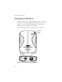
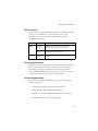
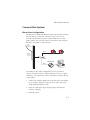
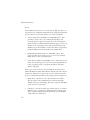
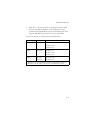
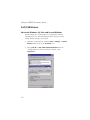
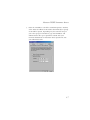
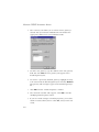
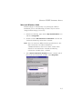
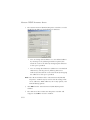
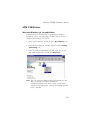
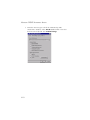
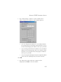
EZ Connect
ADSL USB Modem
ADSL USB Modem
◆
◆
◆
◆
◆
◆
High-speed Internet access over existing phone lines
One RJ-11 ADSL port
Delivers USB plug-and-play installation
Supports full-rate DMT connection
(8 Mbps downstream, 1 Mbps upstream)
Supports econmical G.lite connection
(1.5 Mbps downstream, 512 Kbps upstream)
Graphic interface for ADSL connection management
User Guide
SMC7003-USB
EZ Connect ADSL USB Modem
User Guide
From SMC’s EZ Connect line of feature-rich SOHO solutions
6 Hughes
Irvine, CA 92618
Phone: (949) 707-2400
April 2001
Pub. # 150552-102 R02
Information furnished by SMC Networks, Inc. (SMC) is believed to be accurate and reliable.
However, no responsibility is assumed by SMC for its use, nor for any infringements of patents
or other rights of third parties which may result from its use. No license is granted by
implication or otherwise under any patent or patent rights of SMC. SMC reserves the right to
change specifications at any time without notice.
Copyright © 2001 by
SMC Networks, Inc.
6 Hughes
Irvine, CA 92618
All rights reserved. Printed in Taiwan
Trademarks:
SMC is a registered trademark; and EZ Connect ia a trademark of SMC Networks, Inc. Other
product and company names are trademarks or registered trademarks of their respective
holders.
LIMITED WARRANTY
Limited Warranty
Limited Warranty Statement: SMC Networks, Inc. (“SMC”) warrants its products
to be free from defects in workmanship and materials, under normal use and
service, for the applicable warranty term. All SMC products carry a standard 90-day
limited warranty from the date of purchase from SMC or its Authorized Reseller.
SMC may, at its own discretion, repair or replace any product not operating as
warranted with a similar or functionally equivalent product, during the applicable
warranty term. SMC will endeavor to repair or replace any product returned under
warranty within 30 days of receipt of the product.
The standard limited warranty can be upgraded to a Limited Lifetime* warranty by
registering new products within 30 days of purchase from SMC or its Authorized
Reseller. Registration can be accomplished via the enclosed product registration
card or online via the SMC web site. Failure to register will not affect the standard
limited warranty. The Limited Lifetime warranty covers a product during the Life of
that Product, which is defined as the period of time during which the product is an
“Active” SMC product. A product is considered to be “Active” while it is listed on
the current SMC price list. As new technologies emerge, older technologies become
obsolete and SMC will, at its discretion, replace an older product in its product line
with one that incorporates these newer technologies. At that point, the obsolete
product is discontinued and is no longer an “Active” SMC product. A list of
discontinued products with their respective dates of discontinuance can be found at
http://www.smc.com/smc/pages_html/support.html.
All products that are replaced become the property of SMC. Replacement products
may be either new or reconditioned. Any replaced or repaired product carries
either a 30-day limited warranty or the remainder of the initial warranty, whichever
is longer. SMC is not responsible for any custom software or firmware,
configuration information, or memory data of Customer contained in, stored on, or
integrated with any products returned to SMC pursuant to any warranty. Products
returned to SMC should have any customer-installed accessory or add-on
components, such as expansion modules, removed prior to returning the product
for replacement. SMC is not responsible for these items if they are returned with the
product.
Customers must contact SMC for a Return Material Authorization number prior to
returning any product to SMC. Proof of purchase may be required. Any product
returned to SMC without a valid Return Material Authorization (RMA) number
clearly marked on the outside of the package will be returned to customer at
customer’s expense. For warranty claims within North America, please call our
toll-free customer support number at (800) 762-4968. Customers are responsible for
all shipping charges from their facility to SMC. SMC is responsible for return
shipping charges from SMC to customer.
WARRANTIES EXCLUSIVE: IF AN SMC PRODUCT DOES NOT OPERATE AS
WARRANTED ABOVE, CUSTOMER’S SOLE REMEDY SHALL BE REPAIR OR
REPLACEMENT OF THE PRODUCT IN QUESTION, AT SMC’S OPTION. THE
FOREGOING WARRANTIES AND REMEDIES ARE EXCLUSIVE AND ARE IN LIEU
OF ALL OTHER WARRANTIES OR CONDITIONS, EXPRESS OR IMPLIED, EITHER
LIMITED WARRANTY
IN FACT OR BY OPERATION OF LAW, STATUTORY OR OTHERWISE,
INCLUDING WARRANTIES OR CONDITIONS OF MERCHANTABILITY AND
FITNESS FOR A PARTICULAR PURPOSE. SMC NEITHER ASSUMES NOR
AUTHORIZES ANY OTHER PERSON TO ASSUME FOR IT ANY OTHER LIABILITY
IN CONNECTION WITH THE SALE, INSTALLATION, MAINTENANCE OR USE OF
ITS PRODUCTS. SMC SHALL NOT BE LIABLE UNDER THIS WARRANTY IF ITS
TESTING AND EXAMINATION DISCLOSE THE ALLEGED DEFECT IN THE
PRODUCT DOES NOT EXIST OR WAS CAUSED BY CUSTOMER’S OR ANY THIRD
PERSON’S MISUSE, NEGLECT, IMPROPER INSTALLATION OR TESTING,
UNAUTHORIZED ATTEMPTS TO REPAIR, OR ANY OTHER CAUSE BEYOND THE
RANGE OF THE INTENDED USE, OR BY ACCIDENT, FIRE, LIGHTNING, OR
OTHER HAZARD.
LIMITATION OF LIABILITY: IN NO EVENT, WHETHER BASED IN CONTRACT OR
TORT (INCLUDING NEGLIGENCE), SHALL SMC BE LIABLE FOR INCIDENTAL,
CONSEQUENTIAL, INDIRECT, SPECIAL, OR PUNITIVE DAMAGES OF ANY KIND,
OR FOR LOSS OF REVENUE, LOSS OF BUSINESS, OR OTHER FINANCIAL LOSS
ARISING OUT OF OR IN CONNECTION WITH THE SALE, INSTALLATION,
MAINTENANCE, USE, PERFORMANCE, FAILURE, OR INTERRUPTION OF ITS
PRODUCTS, EVEN IF SMC OR ITS AUTHORIZED RESELLER HAS BEEN ADVISED
OF THE POSSIBILITY OF SUCH DAMAGES.
SOME STATES DO NOT ALLOW THE EXCLUSION OF IMPLIED WARRANTIES OR
THE LIMITATION OF INCIDENTAL OR CONSEQUENTIAL DAMAGES FOR
CONSUMER PRODUCTS, SO THE ABOVE LIMITATIONS AND EXCLUSIONS MAY
NOT APPLY TO YOU. THIS WARRANTY GIVES YOU SPECIFIC LEGAL RIGHTS,
WHICH MAY VARY FROM STATE TO STATE. NOTHING IN THIS WARRANTY
SHALL BE TAKEN TO AFFECT YOUR STATUTORY RIGHTS.
* SMC will provide warranty service for one year following discontinuance from the
active SMC price list. Under the limited lifetime warranty, internal and external
power supplies, fans, and cables are covered by a standard one-year warranty from
date of purchase.
SMC Networks, Inc.
6 Hughes
Irvine, CA 92618
COMPLIANCES
FCC - Class B
This equipment has been tested and found to comply with the limits for a Class B digital
device, pursuant to Part 15 of the FCC Rules. These limits are designed to provide
reasonable protection against harmful interference in a residential installation. This
equipment generates, uses and can radiate radio frequency energy and, if not installed
and used in accordance with instructions, may cause harmful interference to radio
communications. However, there is no guarantee that the interference will not occur in
a particular installation. If this equipment does cause harmful interference to radio or
television reception, which can be determined by turning the equipment off and on, the
user is encouraged to try to correct the interference by one or more of the following
measures:
• Reorient the receiving antenna
• Increase the separation between the equipment and receiver
• Connect the equipment into an outlet on a circuit different from that to which the
receiver is connected
• Consult the dealer or an experienced radio/TV technician for help
FCC - Part 68
The modem is registered with the FCC as compliant with the rules of Part 68 and use of
this modem is subject to the following restrictions:
1. The Federal Communication Commission FCC has established rules which permit this
device to be directly connected to the telephone network. Standardized jacks are
used for these connections. This equipment should not be used on party lines or coin
phones.
2. If this device is malfunctioning, it may also be causing harm to the telephone
network; this device should be disconnected until the source of the problem can be
determined and until repair has been made. If this is not done, the telephone
company can temporarily disconnect service.
3. The telephone company may make changes in its facilities, equipment, operation and
procedures; if such changes affect the compatibility or use of this device, the
telephone company is required to give adequate notice of the changes. You will be
advised of your right to file a complaint with the FCC.
4. If the telephone company requests information on what equipment is connected to
their lines, inform them of:
a The telephone number to which this unit is connected
b The ringer equivalence number
c The USOC jack required
d The FCC Registration number
vii
COMPLIANCES
Items (b) and (d) are indicated on the label. The Ringer Equivalence Number (REN) is
used to determine how many devices can be connected to your telephone line. In most
areas, the sum of the REN of all the devices on any one line should not exceed 5.0. If
too many devices are attached, they may not ring properly.
Industry Canada Required Information
EQUIPMENT ATTACHMENTS LIMITATIONS
To ensure that certified equipment is attached correctly and only to the networks of
participating carriers, the following statement shall accompany each unit of certified
equipment offered for sale. This statement must be included conspicuously in written or
electronic format, at or near the front of each copy of the operating manual, or
accompany other technical information, or be included as a separate sheet. The
required statement is:
“NOTICE: The Industry Canada label identifies certified equipment. This certification
means that the equipment meets telecommunications network protective, operational
and safety requirements as prescribed in the appropriate Terminal Equipment Technical
Requirements documents(s). The department does not guarantee the equipment will
operate to the user’s satisfaction.”
Before installing this equipment, users should ensure that it is permissible to be
connected to the facilities of the local telecommunications company. The equipment
must also be installed using an acceptable method of connection. The customer should
be aware that compliance with the above conditions might not prevent degradation of
service in some situations.
Repairs to certified equipment should be coordinated by a representative designated by
the supplier. Any repairs or alterations made by the user to this equipment, or
equipment malfunctions, may give the telecommunications company cause to request
the user to disconnect the equipment.
Users should ensure for their own protection that the electrical ground connections of
the power utility, telephone lines and internal metallic water pipe system, if present, are
connected together. This precaution may be particularly important in rural areas.
Caution: Users should not attempt to make such connections themselves, but should
contact the appropriate electric inspection authority, or electrician, as appropriate.”
An explanatory note on Ringer Equivalence Numbers (see Section 10.0) and their use
must be provided for the terminal equipment user in the information accompanying the
terminal equipment. A notice similar to the following would be suitable:
“NOTICE: The Ringer Equivalence Number (REN) assigned to each terminal device
provides an indication of the maximum number of terminals allowed to be connected to
a telephone interface. The termination on an interface may consist of any combination
of devices subject only to the requirement that the sum of the ringer equivalence
Numbers of all the devices does not exceed 5.”
viii
COMPLIANCES
EC Conformance Declaration - Class B
SMC contact for these products in Europe is:
SMC Networks Europe,
Edificio Conata II,
Calle Fructuós Gelabert 6-8, 2o, 4a,
08970 - Sant Joan Despí,
Barcelona, Spain.
This information technology equipment complies with the requirements of the Low
Voltage Directive 73/23/EEC and the EMC Directive 89/336/EEC, and carries the CE
Mark accordingly. It conforms to the following specifications:
EMC: EN55022 (1988)/CISPR-22 (1995) Class B
IEC 1000-4-2
4 kV CD, 8 kV AD
IEC 1000-4-3 (1995)
3 V/m
IEC 1000-4-4 (1995)
1.0 kV - (power line)
0.5 kV - (signal line)
IEC 1000-4-6 (1995)
3 Vrms
Industry Canada - Class B
This digital apparatus does not exceed the Class B limits for radio noise emissions from
digital apparatus as set out in the interference-causing equipment standard entitled
“Digital Apparatus,” ICES-003 of the Department of Communications.
Cet appareil numérique respecte les limites de bruits radioélectriques applicables aux
appareils numériques de Classe B prescrites dans la norme sur le matériel brouilleur:
“Appareils Numériques,” NMB-003 édictée par le ministère des Communications.
Japan VCCI Class B
ix
COMPLIANCES
Australia AS/NZS 3548 (1995) - Class B
SMC contact for products in Australia is:
SMC Communications Pty. Ltd.
Suite 18, 12 Tryon Road,
Lindfield NSW2070,
Phone: 61-2-94160437
Fax: 61-2-94160474
x
TABLE
1
CONTENTS
OF
Introduction . . . . . . . . . . . . . . . . . . . . . . . . . . . . 1-1
Key Features . . . . . . . . . . . . . . . . . . . . . . . . . . . . . . . . . . . . . 1-2
2
Hardware Installation . . . . . . . . . . . . . . . . . . . . . 2-1
Package Contents . . . . . . . . . .
Description of Hardware . . . . .
LED Functions . . . . . . . .
Power Requirements . . .
System Requirements . . .
Connect the System . . . . . . . . .
Phone Line Configuration
3
.
.
.
.
.
.
.
.
.
.
.
.
.
.
.
.
.
.
.
.
.
.
.
.
.
.
.
.
.
.
.
.
.
.
.
.
.
.
.
.
.
.
.
.
.
.
.
.
.
.
.
.
.
.
.
.
.
.
.
.
.
.
.
.
.
.
.
.
.
.
.
.
.
.
.
.
.
.
.
.
.
.
.
.
.
.
.
.
.
.
.
.
.
.
.
.
.
.
.
.
.
.
.
.
.
.
.
.
.
.
.
.
.
.
.
.
.
.
.
.
.
.
.
.
.
.
.
.
.
.
.
.
.
.
.
.
.
.
.
.
.
.
.
.
.
.
.
. 2-1
. 2-2
. 2-3
. 2-3
. 2-3
. 2-5
. 2-5
Driver Installation . . . . . . . . . . . . . . . . . . . . . . . . 3-1
Protocol and Device Driver Selection
Prerequisite Information . . . . . . . . . .
Running the Setup Program . . . . . . .
Installing the Modem . . . . . . . . . . . .
4
.
.
.
.
.
.
.
.
.
.
.
.
.
.
.
.
.
.
.
.
.
.
.
.
.
.
.
.
.
.
.
.
.
.
.
.
.
.
.
.
.
.
.
.
.
.
.
.
.
.
.
.
.
.
.
.
.
.
.
.
.
.
.
.
.
.
.
.
.
.
.
.
.
.
.
.
.
.
.
. 3-1
. 3-4
. 3-5
. 3-7
Modifying TCP/IP Networking Options . . . . . . . 4-1
WAN USB Driver . . . . . . . . . . . . . . . . . . . . . . . . . . . . .
Microsoft Windows 98, First and Second Editions
Microsoft Windows 2000 . . . . . . . . . . . . . . . . . . .
LAN USB Driver . . . . . . . . . . . . . . . . . . . . . . . . . . . . . .
Microsoft Windows 98, First and Second Editions
Microsoft Windows 2000 . . . . . . . . . . . . . . . . . . .
ATM USB Driver . . . . . . . . . . . . . . . . . . . . . . . . . . . . .
Microsoft Windows 98, Second Edition . . . . . . . .
Microsoft Windows 2000 . . . . . . . . . . . . . . . . . . . . . . .
.
.
.
.
.
.
.
.
.
.
.
.
.
.
.
.
.
.
.
.
.
.
.
.
.
.
.
. . 4-1
. . 4-1
. . 4-4
. . 4-6
. . 4-6
. . 4-9
. 4-11
. 4-11
. 4-14
5
Customizing Communication Settings . . . . . . . 5-1
6
Updating the Modem Software . . . . . . . . . . . . . . 6-1
7
Control Panel Application . . . . . . . . . . . . . . . . . 7-1
Physical Link Status Tab . . . . . . . . . . . . . . . . . . . . . . . . . . . . . 7-2
i
TABLE OF CONTENTS
System Information Tab . . . . . . . . . . . . . . . . . . . . . . . . . . . . 7-3
Configuration Tab . . . . . . . . . . . . . . . . . . . . . . . . . . . . . . . . . 7-4
8
Uninstalling Modem Software . . . . . . . . . . . . . . . 8-1
A
Troubleshooting . . . . . . . . . . . . . . . . . . . . . . . . . .A-1
You Cannot Connect to the Network . . . . . . . . . . . . . . . . . . . A-1
You Cannot Connect to the Internet . . . . . . . . . . . . . . . . . . . A-1
B
Specifications . . . . . . . . . . . . . . . . . . . . . . . . . . . .B-1
ADSL Specifications . . . . . . . . . . . . . . . . . . . . . . . . . . . . . . . B-1
Physical Characteristics . . . . . . . . . . . . . . . . . . . . . . . . . . . . . B-2
C
ii
Ordering Information . . . . . . . . . . . . . . . . . . . . .C-1
CHAPTER 1
INTRODUCTION
The EZ Connect ADSL USB Modem provides high-speed Internet
access over existing phone lines by making use of previously
unused frequency bandwidth above the voice band. By placing
ADSL signals above the frequency of the voice signal, ADSL
service can coexist on the same line with your telephone service.
ADSL is asymmetric in that it provides a higher data rate in the
downstream (receive) direction than in the upstream (transmit)
direction. Asymmetric operation is ideal for typical home and small
office use where files and information are downloaded more
frequently than uploaded.
The EZ Connect ADSL USB Modem supports both full-rate Discrete
Multi-Tone (G.dmt) connection (T1.413, Issue II) and the more
economical G.lite connection (G.992.2). This modem delivers
concurrent data and voice over a single connection. It also
supports a Rate Adaptive algorithm to maintain high data integrity
under existing conditions, including varied connection lengths and
degraded signal quality. And because all data is encapsulated in
ATM frames, the EZ Connect ADSL USB Modem can be connected
directly to any standards-compliant DSL Access Multiplexer
(DSLAM) at your service provider’s central office, data is then sent
through an ATM backbone, and out to the Internet via an ISP
router. Moreover, there’s no need to install any new lines.
This plug-in ADSL modem provides an always-on digital
connection that eliminates dial-up delays, and transparent
reconnection when initiating any network request. Full support for
the ATM protocol also provides access to a wide range of
advanced transport features, including support for real-time video,
1-1
INTRODUCTION
and other multimedia services requiring guaranteed Quality of
Service (QoS). This device enables true telecommuting for the first
time by providing complete access to Internet and corporate
resources via multiprotocol encapsulation (including TCP/IP,
Novell’s IPX, and Windows NetBEUI network protocols).
Note: Since this modem supports both G.dmt and G.lite, it
requires an external splitter to separate the traffic entering
your premises into data and voice, and also to merge the
data and voice traffic leaving your premises into a single
stream.
Key Features
1-2
•
High-speed Internet access over existing phone lines
•
Full-rate DMT connection (8 Mbps downstream, 1 Mbps
upstream) and economical G.lite connection (1.5 Mbps
downstream, 512 Kbps upstream)
•
Multiprotocol encapsulation of all network protocols, including
TCP/IP, Novell’s IPX, and Windows NetBEUI for complete
access to the Internet and corporate resources
•
Always-on digital connection eliminates dial-up delays, and
transparent reconnection when initiating any network request
•
Concurrent data and voice over a single connection (needs
splitter for both G.dmt and G.lite)
•
Interoperable with Alcatel, Cisco and other DSLAM central
office equipment manufacturers
•
Compatible with various ISP services, using RFC 1483 static IP
assignment or PPP dynamic IP assignment
•
Graphic interface for ADSL connection management
INTRODUCTION
•
Supports Windows 98, Windows 98 Second Edition, and
Windows 2000
•
Delivers USB plug-and-play installation and configuration
1-3
INTRODUCTION
1-4
CHAPTER 2
HARDWARE INSTALLATION
Before installing the SMC ADSL USB Modem verify that you have
all the items listed under “Package Contents.” If any of the items
are missing or damaged, contact your local SMC distributor. Also
be sure you have all the necessary cabling before installing the
modem.
Package Contents
After unpacking the EZ Connect ADSL USB Modem, check the
contents of the box to be sure you’ve received the following
components:
◆
EZ Connect ADSL USB Modem (SMC7003-USB)
◆
1 USB cable, modem to computer (Type B to Type A)
◆
1 CD-ROM with manual and drivers inside
◆
1 registration card (please complete and return to SMC)
Immediately inform your dealer in the event of any incorrect,
missing or damaged parts. If possible, please retain the carton and
original packing materials in case there is a need to return the
product.
Please fill out and return the Warranty Registration Card to SMC or
register on SMC’s Web site. The EZ Connect ADSL USB Modem is
covered by limited-lifetime warranty.
2-1
HARDWARE INSTALLATION
Description of Hardware
Setting up the EZ Connect ADSL USB Modem involves connecting
the device’s cables and installing the driver software. Note that
Windows 98, 98 SE, or 2000 should already be installed on the
computer before installing the driver software.
The following figure shows the components of this modem:
Power LED
(Green )
Data LED
(Green)
USB Port
(Type-B)
RJ-11 Port
Figure 2-1. EZ Connect ADSL USB Modem
2-2
HARDWARE INSTALLATION
LED Functions
The EZ Connect ADSL USB Modem contains two LEDs on the top
panel, one is marked “Data” and the other “Power”. The
operational status of the modem is indicated by the LED
conditions listed below.
LED
Status
Description
Data
Flashing
Green
Indicates the modem is synchronizing its
ADSL/ATM link with the head end.
On
Green
Indicates an ADSL/ATM link has been
established on the RJ-11 port.
On
Green
Power is being supplied to the modem via the
USB bus.
Power
Power Requirements
USB devices can be either self-powered or bus-powered. A device
which has no power connector is bus-powered, and derives its
operating power from the USB connection directly. The EZ
Connect ADSL USB Modem is bus-powered — all you need to do
is plug it into a host PC or self-powered USB hub.
System Requirements
The EZ Connect ADSL USB Modem requires the following PC
features to operate:
•
A host PC that supports the Universal Serial Bus
•
32 MB of RAM and 10 MB of hard disk space
•
Windows 98, 98 SE, or 2000 (with installation files ready)
•
Standard telephone cable with RJ-11 plugs
2-3
HARDWARE INSTALLATION
•
Note that to share Internet access on your network, you will
need to install appropriate Internet-sharing software on one PC.
The ADSL network must meet the following minimum
requirements:
2-4
•
ADSL service from your local telephone company or have
access to an ADSL DSLAM (Digital Subscriber Line Access
Multiplexer)
•
PC configured with fixed IP address or dynamic IP address
assignment via DHCP, Gateway server address, and DNS server
address from your telephone company or network
administrator
•
You also need to get the prerequisite information listed on page
3-4 from your telephone company or network administrator
HARDWARE INSTALLATION
Connect the System
Phone Line Configuration
The EZ Connect ADSL USB Modem supports dual-mode operation
for both full-rate G.dmt and economical G.lite. Your service
provider will therefore attach the outside ADSL line to a data/
phone splitter. You can then connect your phones and computer
directly to the splitter as shown below:
Plain Old
Telephone
System (POTS)
Voice
Residential
Connection
Point (NID)
Splitter
SMC7003-USB
Data
Depending on the wiring configuration used in your house,
separate wall jacks may be used for telephone and voice signals.
Otherwise, you will need to connect your phones and PC directly
to the splitter.
1. Connect the modem’s ADSL port to the data port on the splitter
(or to an RJ-11 telephone wall jack connected to this port)
using standard telephone cable.
2. Insert the USB cable’s Type-B plug (square end) into the
modem’s USB port.
3. Install the driver
2-5
HARDWARE INSTALLATION
4. Install the driver best suited for your connection needs as
described in the next chapter.
2-6
CHAPTER 3
DRIVER INSTALLATION
The CD that comes with the package contains all the software
drivers available for the EZ Connect ADSL USB Modem. A
RELEASE.TXT file that describes the contents of the CD is in the
root directory. LAN, WAN and ATM modem drivers are stored in
separate subdirectories. Select the driver you need for your system.
This modem is fully software upgradeable so that new features
and updates may be added by simply loading a new version of the
device driver onto your PC. Any new or updated drivers can be
downloaded from SMC’s Web site at http://www.smc.com.
The modem drivers that can be used under specific Windows
operating systems are shown on page 3-4. Installation procedures
are described in text files on the driver disk. However, installation
and configuration is described in more detail in this manual.
Protocol and Device Driver Selection
ADSL modems employ ATM (Asynchronous Transfer Mode)
framing. ATM is a protocol that divides packets into small fixed
sized cells for rapid transmission over high-speed networks. The
ATM protocol allows various types of traffic (e.g., data, voice, and
video) to be securely and efficiently carried over the same network.
ATM is being widely deployed by telecommunications carriers in
their backbone networks. Two types of ATM connections are
possible, PVC (Permanent Virtual Circuit) and SVC (Switch Virtual
Circuit). The EZ Connect ADSL USB Modem currently only
supports the PVC connections types through WAN, LAN and ATM
3-1
DRIVER INSTALLATION
drivers.
Several different protocols are used on top of ATM. The protocol
required in your configuration depends on the equipment deployed
by your DSL service provider. There are several possibilities:
•
Point to Point Protocol (PPP) Over ATM (RFC 2364) - PPP
provides session setup, user authentication (login), and
encapsulation for upper layer protocols such as IP (Internet
Protocol). The use of PPP makes the modem appear as a dial- up
modem to the operating system. Dial-Up Networking under
Windows is used to establish a connection. PPP is supported by
the WAN (Wide Area Network) driver and ATM driver.
•
Bridged/Routed Ethernet/IP over ATM (RFC 1483) - This
protocol makes the modem appear as a local area network
(LAN) device to the operating system.
•
Classical IP and ARP over ATM (RFC 1577) - This protocol also
makes the modem appear as a local area network (LAN) device
to the operating system. It supports IP address and ATM
address mapping.
Three types of device drivers are provided for the EZ Connect
ADSL USB Modem, WAN, ATM and LAN. Note that all three drivers
support the ATM protocol. The proper choice of driver depends
on your combination of Windows operating system and protocol.
3-2
•
WAN driver - this driver causes the modem to resemble a
dial-up modem. Call establishment is performed through
Windows Dial-Up Networking. This driver supports PPP (RFC
2364) with PVC connections.
•
LAN driver - this driver makes the modem appear as a LAN or
Ethernet device. Connection establishment is automatic. This
driver supports Multiprotocol Encapsulation over ATM (RFC
1483) with PVC connections.
DRIVER INSTALLATION
•
ATM driver - this driver works in conjunction with the ATM
services provided by Windows. Call establishment is also
performed through Windows Dial-Up Networking. This driver
supports PPP (RFC 2364) with PVC or SVC connections.
The device drivers are summarized in the table below:
Driver Type
Protocols
Windows OS
WAN*
RFC 2364
Windows 98
Windows 98 SE
Windows 2000
LAN
RFC 1483
Windows 98
Windows 98 SE
Windows 2000
ATM*
RFC1577
Windows 98 SE
RFC 2364
Windows 2000
* Windows Dial-up Networking and Dial-up ATM Support should be
installed in your operating system prior to installing these drivers.
3-3
DRIVER INSTALLATION
Prerequisite Information
The following information may be required, depending on the
driver you install. Contact your DSL service provider before
proceeding with software installation.
•
IP Address Settings - the software installation process allows the
server to dynamically assign IP Address settings. If your
application requires a static setting for specific address
information you will need to know the following:
IP Address
Subnet Mask (for Bridged Ethernet applications only)
Default Gateway (for Bridged Ethernet applications only)
•
Name Server Information - the modem software installation
process allows the server to dynamically assign Name Server
Address settings. If your application requires a static setting for
specific address information you will need to know the
following:
Primary DNS Address
Secondary DNS Address
Primary WINS Address
Secondary WINS Address
3-4
•
Mode (for LAN applications only)
•
Virtual Path ID (VPI)*
•
Virtual Circuit ID (VCI)*
•
Encapsulation type*
•
Modulation type*
•
User Name (for PPP applications only)
•
Password (for PPP applications only)
DRIVER INSTALLATION
* These items are only required if you are not using default values.
3-5
DRIVER INSTALLATION
Running the Setup Program
Note: Please view the README.TXT file on the CD for product
related information.
1. Start up your PC with the modem disconnected.
2. After Windows starts, insert the CD-ROM that comes with the
EZ Connect ADSL USB Modem in your CD drive, and click
Setup.exe to start the installation procedure.
3. The “Welcome” window provides an opportunity to quit the
setup process to exit all Windows programs before continuing.
If the Windows programs were previously closed, click Next.
4. The “Start Copying Files” window displays the default driver
settings. To automatically select the default settings, click Next
and continue to Step 7. To change the driver settings, click
Customize and continue to step 5.
3-6
DRIVER INSTALLATION
5. Specify the driver type and click Next. Then specify the VPI
(Virtual Path), VCI (Virtual Channel), Layer 3 Encapsulation
type, and Modulation type, and click Next. Check with your
service provider for the correct settings.
6. The “Start Copying Files” window will be redisplayed. You
may review the current settings and click Customize or Back
to change the settings. Click Next to accept the current
settings; a message will be displayed indicating that files are
being copied.
7. The “Setup Complete” window indicates successful completion
of the installation process. Select the Yes, I want to restart my
computer now option, remove any disks from their drives, and
click Finish. Your PC will reboot. Continue with the Modem
Installation section.
3-7
DRIVER INSTALLATION
Installing the Modem
Note: For Windows 98 SE applications, you may need the
Windows 98 SE source files to complete the installation.
Microsoft Windows has an auto-detect feature, known as “Plug
and Play,” that is capable of identifying when new hardware has
been installed. After you run the setup program, reboot your PC,
and then connect the EZ Connect ADSL USB Modem to your PC.
1. Insert the rectangular end of a USB cable into the USB port of
your PC, and the square end of the cable into the USB port of
the USB modem. It will be detected automatically and
messages will be displayed as the modem software is installed.
2. For Windows 2000 applications, the “Digital Signature Not
Found” window may appear warning that the installation
software is not a digitally signed version. A digital signature is
not necessary; SMC has tested the software with Windows
2000. Click Yes to allow the installation to continue. (We will
be releasing a digitally signed version of the driver in the near
future.)
3. For Windows 2000 applications, the “Found New Hardware
Wizard” window indicates the modem has been installed and
suggests you reboot the system to have new settings take
effect. Click Finish.
4. A message will be displayed confirming that you want to
reboot the system, click Yes.
5. Once the PC has rebooted, installation of the EZ Connect ADSL
USB Modem is complete.
3-8
DRIVER INSTALLATION
Note: Regardless of the driver type installed, the installation
procedure will automatically configure the TCP/IP settings.
If you need to change these settings, refer to Chapter 4:
“Modifying TCP/IP Networking Options.”
3-9
DRIVER INSTALLATION
3-10
CHAPTER 4
MODIFYING TCP/IP
NETWORKING OPTIONS
WAN USB Driver
Microsoft Windows 98, First and Second Editions
TCP/IP settings are automatically set up during the software
installation process. The following procedure may be used to
change TCP/IP settings, if necessary.
1. From your PC desktop, double click the My Computer icon.
2. From the “My Computer” window, double click the Dial-Up
Networking icon.
3. From the “Dial-Up Networking” window, right click on the
SMC Dial-Up PPP Connection icon and click Properties.
4-1
MODIFYING TCP/IP NETWORKING OPTIONS
Note: The icon name may differ from that specified above. The
SMC connection icon will be identified as
“DSLWanUsb-Line0” in the Device Name column when
details are viewed from the “Dial-Up Networking” window
(View - Details).
4. From the “Server Types” tab of the “SMC Dial-Up PPP
Connection” window, select TCP/IP (marked with a check in
the box to the left) and click TCP/IP Settings.
4-2
MODIFYING TCP/IP NETWORKING OPTIONS
5. The “TCP/IP Settings” window is used to modify the IP
address, Name Server addresses and/or default gateway.
•
You can change the IP address to a user-defined address
by selecting Specify an IP address (click inside the circle to
the left of it) and typing the address in the space provided.
•
You can change the Name Server addresses to user-defined
addresses by selecting Specify name server addresses (click
inside the circle to the left of it) and typing the addresses
in the spaces provided.
•
Change the default gateway by leaving the box blank to the
left of Use default gateway on remote network.
Click OK.
6. The “SMC Dial-Up PPP Connection” window will be
redisplayed. Click OK to close the window.
4-3
MODIFYING TCP/IP NETWORKING OPTIONS
Microsoft Windows 2000
TCP/IP settings are automatically set up during the software
installation process. The following procedure may be used to
change TCP/IP settings, if necessary.
1. From your PC desktop, right click the My Network Places
icon and select Properties.
2. From the “Network and Dial-Up Connections” window, right
click on the SMC Dial-Up PPP Connection icon and click
Properties.
Note: The icon name may differ from that specified above. The
SMC connection icon will be identified as
“DSLWanUsb-Line0” in the Device Name column when
details are viewed from the “Network and Dial-Up
Connections” window (View - Details).
3. From the “Networking” tab of the “SMC Dial-UP PPP
Connection Properties” window, select Internet Protocol
(TCP/IP) and click Properties.
4-4
MODIFYING TCP/IP NETWORKING OPTIONS
4. The “Internet Protocol (TCP/IP) Properties” window is used to
modify the IP address and DNS Server addresses.
•
You can change the IP address to a user-defined address
by selecting Use the following IP address (click inside the
circle to the left of it) and typing the address in the space
provided.
•
You can change the DNS Server addresses to user-defined
addresses by selecting Use the following DNS server
addresses (click inside the circle to the left of it) and typing
the addresses in the spaces provided.
Note: The “Advanced” button of the “Internet Protocol (TCP/IP)
Properties” window may be used to alter DNS addresses,
WINS addresses and IP security settings.
5. Click OK from the “Internet Protocol (TCP/IP) Properties”
window.
6. The “SMC Dial-Up PPP Connection Properties” window will
reappear. Click OK to close the window.
4-5
MODIFYING TCP/IP NETWORKING OPTIONS
LAN USB Driver
Microsoft Windows 98, First and Second Editions
TCP/IP settings are automatically set up during the software
installation process. The following procedure may be used to
change TCP/IP settings, if necessary.
1. From the “Control Panel” window (Start - Settings - Control
Panel) double click on the Network icon.
2. Select TCP/IP -> SMC ADSL USB LAN Modem from the
“Configuration” tab of the “Network” window. Click
Properties.
4-6
MODIFYING TCP/IP NETWORKING OPTIONS
3. From the “IP Address” tab of the “TCP/IP Properties” window,
select either the Obtain an IP address Automatically or Specify
an IP Address option, depending on your network setup. If
you select Specify an IP address, type the IP Address and
Subnet Mask in the spaces provided. Consult with your
network administrator to determine which option best suits
your individual needs.
4-7
MODIFYING TCP/IP NETWORKING OPTIONS
4. The “Gateway” tab allows you to add or remove gateways.
Consult with your network administrator to determine the
appropriate addresses for your individual needs.
5. To add a new gateway, type the address in the New gateway
field and click Add. The new gateway will appear in the
Installed gateways list.
6. To remove a previously installed gateway, highlight the entry
to be removed in the Installed gateways list and click Remove.
The gateway will no longer appear in the Installed gateways
list.
7. Click OK from the “TCP/IP Properties” window.
8. The “Network” window will reappear. Click OK to end the
modifying TCP/IP options session.
9. If you have made changes to TCP/IP properties, you will be
asked to restart/reboot your PC. Click Yes, and your PC will
restart.
4-8
MODIFYING TCP/IP NETWORKING OPTIONS
Microsoft Windows 2000
TCP/IP settings are automatically set up during the software
installation process. The following procedure may be used to
change TCP/IP settings, if necessary.
1. From the PC desktop, right click the My Network Places icon
and select Properties.
2. Double click the SMC Local Area Connection icon from the
“Network and Dial-Up Connections” window.
Note: The icon name may differ from that specified above. The
SMC connection icon will be identified as
“DSLLanUsb-Line0” in the Device Name column when
details are viewed from the “Network and Dial-Up
Connection” window (View - Details).
3. Select Internet Protocol (TCP/IP) from the “General” tab of
the “Local Area Connection” window. Click Properties.
4-9
MODIFYING TCP/IP NETWORKING OPTIONS
4. The “Internet Protocol (TCP/IP) Properties” window is used to
modify the IP addresses and DNS Server addresses.
•
You can change the IP address to a user-defined address
by selecting Use the following IP address option (click
inside the circle to the left of it) and typing the addresses
in the spaces provided.
•
You can change the DNS Server addresses to user-defined
addresses by selecting Use the following DNS server
addresses (click inside the circle to the left of it) and typing
the addresses in the spaces provided.
Note: The Advanced button of the “Internet Protocol (TCP/IP)
Properties” window may be used to alter IP settings, DNS
server addresses, WINS addresses, IP security options, and
TCP/IP filtering options.
5. Click OK from the “Internet Protocol (TCP/IP) Properties”
window.
6. The “SMC Local Area Connection Properties” window will
reappear. Click OK to close the window.
4-10
MODIFYING TCP/IP NETWORKING OPTIONS
ATM USB Driver
Microsoft Windows 98, Second Edition
TCP/IP settings are automatically set up during the software
installation process. The following procedure may be used to
change TCP/IP settings, if necessary.
1. From your PC desktop, double click the My Computer icon.
2. From the “My Computer” window, double click the Dial-Up
Networking icon.
3. From the “Dial-Up Networking” window, right click on the
SMC ADSL Connection icon and click Properties.
Note: The icon name may differ from that specified above. The
SMC connection icon will be identified as
“DSLAtmUsb-Line0” in the Device Name column when
details are viewed from the “Dial-Up Networking” window
(View - Details).
4-11
MODIFYING TCP/IP NETWORKING OPTIONS
4. From the “Server Types” tab of the “SMC Dial-Up PPP
Connection” window, select TCP/IP (marked with a check in
the box to the left) and click TCP/IP Settings.
4-12
MODIFYING TCP/IP NETWORKING OPTIONS
5. The “TCP/IP Settings” window is used to modify the IP
address, Name Server addresses and/or default gateway.
•
You can change the IP address to a user-defined address
by selecting Specify an IP address (click inside the circle to
the left of it) and typing the address in the space provided.
•
You can change the Name Server addresses to user-defined
addresses by selecting Specify name server addresses (click
inside the circle to the left of it) and typing the addresses
in the spaces provided.
•
You can change the default gateway by leaving the box blank
to the left of Use default gateway on remote network.
Click OK.
6. The “SMC Dial-Up PPP Connection” window will be
redisplayed. Click OK to close the window.
4-13
MODIFYING TCP/IP NETWORKING OPTIONS
Microsoft Windows 2000
TCP/IP settings are automatically set up during the software
installation process. The following procedure may be used to
change TCP/IP settings, if necessary.
1. From your PC desktop, right click the My Network Places
icon and select Properties.
2. From the “Network and Dial-Up Connections” window, right
click on the SMC Dial-Up PPP Connection icon and click
Properties.
Note: The icon name may differ from that specified above. The
SMC connection icon will be identified as
“DSLAtmUsb-Line0” in the Device Name column when
details are viewed from the “Network and Dial-Up
Connections” window (View - Details).
4-14
MODIFYING TCP/IP NETWORKING OPTIONS
3. From the “Networking” tab of the “SMC Dial-Up PPP
Connection Properties” window, select Internet Protocol
(TCP/IP) and click Properties.
4-15
MODIFYING TCP/IP NETWORKING OPTIONS
4. The “Internet Protocol (TCP/IP) Properties” window is used to
modify the IP address and DNS Server addresses.
•
You can change the IP address to a user-defined address
by selecting Use the following IP address (click inside the
circle to the left of it) and typing the address in the space
provided.
•
You can change the DNS Server addresses to user-defined
addresses by selecting Use the following DNS server
addresses (click inside the circle to the left of it) and typing
the addresses in the spaces provided.
Note: The “Advanced” button of the “Internet Protocol (TCP/IP)
Properties” window may be used to alter DNS address,
WINS address and IP security settings.
5. Click OK from the “Internet Protocol (TCP/IP) Properties”
window.
6. The “SMC Dial-Up PPP Connection Properties” window will
reappear. Click OK to close the window.
4-16
CHAPTER 5
CUSTOMIZING
COMMUNICATION SETTINGS
Once the SMC EZ Connect ADSL USB Modem and software have
been installed the communication settings may be easily updated
by performing the following steps
1. From your PC desktop click Start - Programs - SMC DSL
Modem - Configure. A notification message will appear
indicating that the setup process has begun.
2. Click Settings from the “DSL Modem Installer” window.
3. The “Communication Settings” window will be displayed.
Make the necessary changes to the VPI, VCI, Encapsulation
type and/or Modulation type and click Apply.
4. The “Setup Complete” window indicates successful completion
of the customization process. Select the “Yes, I want to restart
my computer now” option, remove any disks from their drives,
and click Finish. Your PC will reboot.
5-1
CUSTOMIZING COMMUNICATION SETTINGS
5-2
UPDATING
CHAPTER 6
THE MODEM
SOFTWARE
Once the EZ Connect ADSL USB Modem has been installed,
updating to a new version of the software is a simple process as
detailed below.
1. From your PC desktop click Start - Programs - SMC DSL
Modem - Configure. A notification message will appear
indicating that the setup process has begun.
2. Click Update from the “DSL Modem Installer” window.
3. A message will be displayed asking you to confirm the update;
click Yes.
4. The “Select installation location” window will be displayed.
Indicate the location of the Setup files and click OK.
5. Since updating the modem software requires removing the old
version and installing a new one, a message will be displayed
informing you not to unplug the USB modem cable until the
uninstall process has been completed. Click OK.
6. A message will be displayed indicating the software is being
uninstalled.
7. The “Setup Complete” window indicates successful completion
of this portion of the updating process. Click Finish.
6-1
UPDATING THE MODEM SOFTWARE
8. Processing will continue with Step 2 of “Running the Setup
Program.” Please turn to page 3-6, Step 2 to complete the
installation portion of the updating process.
6-2
CHAPTER 7
CONTROL PANEL
APPLICATION
The EZ Connect ADSL USB Modem control panel program
provides a quick and easy way to configure and check the
performance of the modem and the ADSL connection. When
open, the monitor window updates every 2 seconds.
Note: The following screen shots of the modem Control Panel are
preliminary and are not final, as the Control Panel
functionality is continually being upgraded and improved.
Updated screen shots of the finished Control Panel will be
available in revised versions of this manual through SMC.
From the “Control Panel” window (Start - Settings - Control
Panel), double click the SMC DSL Modem icon, or just double
click the SMC globe icon in the system tray.
Note: To access the modem Control Panel, the driver must be
running. Also, make sure the USB cable is plugged into the
modem.
7-1
CONTROL PANEL APPLICATION
Physical Link Status Tab
The “Physical Link Status” tab of the “SMC DSL Modem” window
(Control Panel) allows you to review the current state of the EZ
Connect ADSL USB Modem and connection. When the green
indicator is on in the Link Status field, it indicates that a
connection has been made. This indicator blinks while a
connection is being established. The Transmitting and Receiving
data activity are shown separately by individual flashing yellow
indicators.
7-2
CONTROL PANEL APPLICATION
System Information Tab
The “System Information” tab displays the release number of the
EZ Connect ADSL USB Modem driver, the firmware release
number, and the control panel version that you are currently using.
7-3
CONTROL PANEL APPLICATION
Configuration Tab
The “Configuration” tab offers driver appropriate Modulation,
Encapsulation, and VPI and VCI values. If you are using a WAN or
ATM driver, only the Modulation type will be displayed and may
be modified. For LAN driver applications, you will be able to view
and modify the Modulation type, Encapsulation type, and VPI and
VCI values.
7-4
CHAPTER 8
UNINSTALLING MODEM
SOFTWARE
You can remove the SMC EZ Connect ADSL USB Modem software
drivers by performing the following steps.
Note: The USB cable should not be unplugged until after the
uninstall process has been completed. For Windows 98
applications, the cable must be unplugged immediately
following Step 6 below.
1. From your PC desktop click Start - Programs - SMC DSL
Modem - Uninstall. A notification message will appear
indicating that the setup process has begun.
2. Click Remove in the “DSL Modem Installer” window.
3. A message will be displayed asking you to confirm removal of
the USB ADSL modem software, click Yes.
4. The “Information” window will be displayed reminding you
not to unplug the USB cable until the uninstall process has
been completed. Click OK.
5. A message will be displayed indicating the software is being
removed.
6. The “Setup Complete” window indicates successful completion
of the uninstall process. Click Finish.
8-1
UNINSTALLING MODEM SOFTWARE
Note: The screen for Windows 2000 applications will not ask you
to reboot the system. Click Finish to complete the Uninstall
process.
7. Unplug the USB cable from the PC.
Note: The USB cable must be unplugged before the system is
rebooted. For Windows 98 applications, the cable must be
unplugged immediately since the reboot process was
initiated in Step 6 above.
8-2
APPENDIX A
TROUBLESHOOTING
Check the following troubleshooting points before contacting SMC
Technical Support.
You Cannot Connect to the Network
•
Check the phone and USB cables for wear or loose wires; and
replace any defective cables if necessary. Make sure the cable
is securely attached to the modem’s RJ-11 port; and that the
modem is connected to your ADSL service provider via an RJ-11
wall socket or splitter.
•
If your PPP connection fails to respond, hang up and dial again.
PPP may fail to connect when you first dial in due to
synchronization problems.
•
If the Data LED is off, review the driver installation process to
be sure that the driver was correctly installed. Make sure the
correct software driver was installed for your operating system.
A failed or aborted installation may leave some system files or
drivers that interfere with a new installation. If necessary,
remove the EZ Connect ADSL USB Modem driver, and try
reinstalling it.
You Cannot Connect to the Internet
•
Click on the Network icon in the Control Panel and enter the
required TCP/IP settings specified by your Internet Service
A-1
TROUBLESHOOTING
Provider. Then reboot your computer to enable the new settings.
A-2
APPENDIX B
SPECIFICATIONS
ADSL Specifications
Standards Conformance
Basic ADSL:
ANSI T1.413 Issue II (full rate ADSL), ITU G.992.1
(G.dmt), ITU G.992.2 (G.lite), G.994.1 (G.hs)
Transport Protocols:
RFC 1557 (IP/ATM), RFC 2364 (PPP/ATM)
ATM Attributes:
ATM Transmission Convergence, ATM Framing (with traffic
shaping), ATM SAR/AAL5, ATM Forum UNI3.1 signalling,
ATM UBR Service Class
ADSL Service
Service Type:
Full rate Discrete Multi-Tone ADSL (G.dmt), and
Splitterless ADSL (G.lite)
Data Rate:
G.dmt: 8 Mbps (downstream), 1 Mbps (upstream)
G.lite: 1.5 Mbps (downstream), 512 Kbps (upstream)
Media Type:
Simultaneous data/voice (can coexist with HPNA)
Service Provider:
Digital Subscriber Line Access Multiplexer (DSLAM)
B-1
SPECIFICATIONS
Media Connection
USB cable connection to PC -90-ohm shielded USB cable, max length
5 m (16 ft)
RJ-11 phone wire connection to ADSL provider
PC Requirements
Host Interface:
USB Specification 1.1 or up
System Requirements:
A PC and Windows 98, 98 Second Edition, or 2000 operating
system
Physical Characteristics
Ports
Upstream: 1 USB Type-B
USB spec. 1.1 differential and bi-directional, 12 Mbps
(high-speed device)
Downstream: RJ-11
Phone wire connection to ADSL service provider
LEDs
Power, Data
Dimensions
13.0 x 13.0 x 2.9 cm (5.12 x 5.12 x 1.14 in)
Weight
5.29 oz. (150 g)
Input Power
+5VDC, 500mA (maximum)
(bus powered from USB host controller or hub)
Power Consumption
2.50 Watts maximum (from USB host)
B-2
SPECIFICATIONS
Temperature
Operating 32 to 104°F (0 to 40°C)
Storage -40 to 160°F (-40 to 70°C)
Humidity
5% to 95% (non-condensing)
Compliances
CE Mark
Emissions
FCC Class B
VCCI Class B
Industry Canada Class B
EN55022 (CISPR 22) Class B
C-Tick - AS/NZS 3548 (1995) Class B
Immunity
IEC 1000-4-2/3/4/6
Safety
UL 1950
EN60950 (T‹V)
CSA 22.2 No. 950
Warranty
Limited Lifetime
B-3
SPECIFICATIONS
B-4
APPENDIX C
ORDERING INFORMATION
EZ Connect ADSL Products and Accessories
SMC7003-USB
ADSL USB Modem
C-1
ORDERING INFORMATION
C-2
FOR TECHNICAL SUPPORT, CALL:
From U.S.A. and Canada (24 hours, 7 days a week)
(800) SMC-4-YOU; (949) 707-2400; (949) 707-2460 (Fax)
From Europe (8:00 AM - 5:30 PM UK Greenwich Mean Time)
44 (0) 1188 748740; 44 (0) 1189 748741 (Fax)
INTERNET
E-mail addresses:
[email protected]
[email protected]
Driver updates:
http://www.smc.com/support.html
World Wide Web:
http://www.smc.com/
FTP Site:
ftp.smc.com
FOR LITERATURE OR ADVERTISING RESPONSE, CALL:
U.S.A. and Canada:
Spain:
UK:
Southern Europe:
Central/Eastern Europe:
Nordic:
Middle East:
South Africa:
PRC:
Taiwan:
Asia Pacific:
Korea:
Japan:
Australia:
India:
6 Hughes
Irvine, CA 92618
Phone: (949) 707-2400
(800) SMC-4-YOU;
34-93-477-4920;
44 (0) 1188 748700;
33 (1) 41.18.68.68;
49 (0) 89 92861-200;
46 (8) 564 33145;
971-48818410;
27 (0) 11-3936491;
86-10-6235-4958;
886-2-2747-4780;
(65) 238 6556;
82-2-553-0860;
81-45-224-2332;
61-2-9416-0437;
91-22-8204437;
Fax (949) 707-2460
Fax 34-93-477-3774
Fax 44 (0) 1189 748701
Fax 33 (1) 41.18.68.69
Fax 49 (0) 89 92861-230
Fax 46 (8) 87 62 62
Fax 971-48817993
Fax 27 (0) 11-3936491
Fax 86-10-6235-4962
Fax 886-2-2747-9220
Fax (65) 238 6466
Fax 82-2-553-7202
Fax 81-45-224-2331
Fax 61-2-9416-0474
Fax 91-22-8204443
Model Number: SMC7003-USB
Publication Number: 150552-102 E042001-R02