1
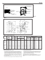
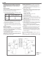
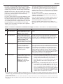
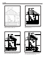
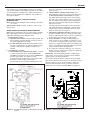
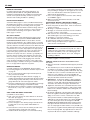
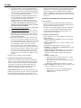
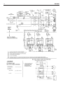
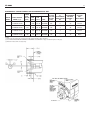
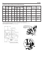
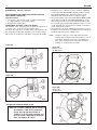
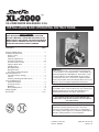
XL-2000
™
OIL-FIRED WATER BOILERS/NO. 2 OIL
INSTALLATION AND OPERATING INSTRUCTIONS
SAFETY WARNING:
KEEP BOILER AREA CLEAR AND FREE FROM COMBUSTIBLE MATERIALS, GASOLINE AND OTHER FLAMMABLE VAPORS AND LIQUIDS. FAILURE TO ADHERE TO
ABOVE SAFETY WARNING, MAY RESULT IN PERSONAL
INJURY OR DEATH AND PROPERTY DAMAGE.
CONTENTS . . . . . . . . . . . . . . . . . . . . . . . . . . . . . . . . . .PAGE
Ratings and Dimensions . . . . . . . . . . . . . . . . . . . . . . . . . . . .2
Installation Requirements:
Boiler Location . . . . . . . . . . . . . . . . . . . . . . . . . . . . . . . . .3
Clearances . . . . . . . . . . . . . . . . . . . . . . . . . . . . . . . . . . . .3
Chimney Requirements . . . . . . . . . . . . . . . . . . . . . . . . . .3
Air Supply and Venting . . . . . . . . . . . . . . . . . . . . . . . . . .3,4
Controls and Accessories . . . . . . . . . . . . . . . . . . . . . . . . .5
Piping for Water Units . . . . . . . . . . . . . . . . . . . . . . . . . . . .5
Installing Burner . . . . . . . . . . . . . . . . . . . . . . . . . . . . . . . .5
Oil Supply Piping . . . . . . . . . . . . . . . . . . . . . . . . . . . . . . .5
Wiring the Boiler . . . . . . . . . . . . . . . . . . . . . . . . . . . . . . . .5
Vent Piping and Draft Regulator . . . . . . . . . . . . . . . . . . . .5
Operating Instructions:
Precautions Before Starting . . . . . . . . . . . . . . . . . . . . . . .7
Start-up . . . . . . . . . . . . . . . . . . . . . . . . . . . . . . . . . . . . . . .7
Cleaning and Filling New Water Boiler . . . . . . . . . . . . . . .8
Care and Maintenance:
Extended Shutdown . . . . . . . . . . . . . . . . . . . . . . . . . . . . .8
Freezing Protection . . . . . . . . . . . . . . . . . . . . . . . . . . . . . .8
Oil Burner . . . . . . . . . . . . . . . . . . . . . . . . . . . . . . . . . . . . .9
General Maintenance . . . . . . . . . . . . . . . . . . . . . . . . . . . .9
Wiring Diagrams . . . . . . . . . . . . . . . . . . . . . . . . . . . . . . . . .10
Burner Data . . . . . . . . . . . . . . . . . . . . . . . . . . . . . . . . . .11,12
IMPORTANT: The installation of this equipment must conform to the requirements of the authority having jurisdiction
or, in the absence of such requirements, to the Installation of
Oil Burning Equipment, ANSI/NFPA 31, latest edition, and to
the National Electrical Code ANSI/NFPA 70, latest edition.
The installation must also conform to the additional requirements in this Slant/Fin Instruction Manual. Where there is any
difference, the more stringent requirement shall govern.
In addition, where required by the authority having jurisdiction,
the installation must conform to American Society of Mechanical
Engineers Safety Code for Controls and Safety Devices for
Automatically Fired Boilers, No. CSD-1, latest edition.
THIS MANUAL MUST BE LEFT WITH OWNER AND
SHOULD BE HUNG ON OR ADJACENT TO THE BOILER
FOR REFERENCE.
IMPORTANT: This boiler must be installed, serviced and
repaired by a trained, experienced, service technician,
licensed for the installation and servicing of oil burning hot
water heating system equipment or otherwise qualified by the
authorities having jurisdiction over the installation.
Printed in U.S.A.305
Part No. 48-0090
Publication No. XL-40
Revision C
XL-2000
2
1/4 NPT PRESSURE
& TEMPERATURE TAPPING
TOP VIEW
FRONT VIEW
1/2 NPT
CONTROL TAPPING
3/4" RELIEF
VALVE TAPPING
1 1/2 SUPPLY
TAPPING
1 1/2 ALTERNATE
REAR RETURN
1 1/2 RETURN
TAPPING
3/4 REAR DRAIN
1/2" AIR VENT
OR EXPANSION TANK
TAPPING
Figure 1.
Figure 2.
TABLE 1: Ratings and Dimensions
BOILER
MODEL
NO.
I=B=R
BURNER
CAPACITY
OIL INPUT † §
GPH
XL-20
0.65
XL-30H 0.85
XL-30
1.00
1.15
XL-40H 1.25
XL-40
1.35
1.55
XL-50
1.80
2.00
BTUH
D.O.E.
HEATING
CAPACITY
MBH *
WATER
I=B=R
WATER
NET
RATING
MBH *
91,000
119,000
140,000
161,000
175,000
189,000
217,000
252,000
280,000
78
104
121
138
152
162
186
217
239
68
90
105
120
132
141
162
189
206
DIMENSIONS (inches) #
I=B=R
CHIMNEY SIZE
NOM. RECT I.D. ROUND
X HEIGHT‡ X HEIGHT
(in x in x ft)
(in x ft)
8
8
8
8
8
8
8
8
8
x8x15
x8x15
x8x15
x8x15
x8x15
x8x15
x8x15
x8x15
x8x15
6
6
6
6
7
7
7
8
8
Standard working pressure 30 psi.
All boilers hydrostatically tested — A.S.M.E.
* For forced hot water heating systems where the boiler and all piping are
located within the area to be heated, the boiler may be selected on the basis
of D.O.E. capacity output. The net I=B=R output ratings shown are based on
an allowance for piping and pickup of 1.15 (water) or 1.33 (steam). D.O.E.
capacity output is divided by the allowance to obtain net rating. The Slant/Fin
Technical Service department should be consulted before selecting a boiler
for unusual piping and pickup requirements such as intermittent system operation, extensive piping, etc.
† Ratings apply to the use of light oil at 140,000 Btu per gallon and apply only
when burner models listed on pages 11 and 12 of this manual are used, and
x
x
x
x
x
x
x
x
x
15
15
15
15
15
15
15
15
15
AFUE %
BOILER
LENGTH
“A”
83.56
86.00
85.04
84.12
86.00
85.05
84.38
85.00
84.19
811/16
123/16
123/16
123/16
1511/16
1511/16
1511/16
193/16
193/16
FRONT TO FLUE
FLUE
DIA.
“B”
“C”
49/16
65/16
65/16
65/16
81/16
81/16
81/16
913/16
913/16
6¶
6
6
6
7
7
7
8
8
CIRCULATOR APPROX.
OVERALL
SUPPLY
FLANGE “D” LENGTH
“E”
NPT
11/4
11/4
11/4
11/4
11/4
11/4
11/4
11/2
11/2
253/8
287/8
287/8
287/8
323/8
323/8
323/8
357/8
357/8
are properly adjusted to produce 13% CO2.
‡ Nominal clay tile liner dimensions.
§ Water boiler models XL-30 and larger have two firing rates. The boiler is factory shipped at the lower firing rate. To obtain the higher firing rate, refer to
the XL-2000 boiler installation instructions for the appropriate field adjustments. “H” models have only one firing rate.
¶ Oblong flue collar. Fits 6” dia. vent connectors.
# All dimensions subject to normal manufacturing tolerance.
NOTE: All boilers under 300,000 Btuh (87.9 kw) input are tested and rated for
capacity under the U.S. Department of Energy (D.O.E.) Test Procedures for
Boilers.
XL-2000
3
THE INSTALLATION INSTRUCTIONS IN THIS MANUAL
ARE ABBREVIATED. SEE THE FRONT COVER OF THIS
MANUAL FOR REFERENCES TO CODES AND STANDARDS.
BOILER LOCATION
Provide a level, solid foundation for the boiler. Location should
be near the chimney so that the Flue Pipe Connector or
Breeching to the chimney is short and direct.
A. The foundation must be capable of supporting the weight
of the boiler when filled with water:
Boiler
Size
Approximate Total Weight of Boiler
Assembly*, filled with water
XL-20
XL-30
XL-40
XL-50
317
405
493
581
* Includes burner, circulator and controls
B. The XL-2000 Boiler has full wet base sections which surround fire-box for maximum heat absorption of burning
fuel, and low floor temperature.
C. If boiler is to be located over buried conduit containing
electric wires or telephone cables, consult local codes or
the National Board of Fire Underwriters for specific requirements.
MINIMUM CLEARANCE
Provide accessibility clearance of 24" from surfaces requiring
servicing (top and front) and 18" on any side requiring passage. The boiler shall be installed with the following MINIMUM
clearances from combustible materials:
A. CHIMNEY CONNECTOR-18"
B. BACK AND SIDES- 6" EXCEPT as limited by 18" clearance from chimney connector
NOTE: Except in closets and alcoves, clearances above in (A)
and (B) may be reduced by providing forms of protection as
specified in NFPA 31, latest edition.
CHIMNEY REQUIREMENTS (see NFPA 31, latest edition)
A. The chimney must be constructed in accordance with all
local applicable codes and the National Board of Fire
Underwriters. See boiler models and rating table shown on
page 2 for chimney sizes.
B. Check chimney condition.
Existing chimneys and stacks may have deteriorated; without repairs their use would be hazardous. Before connecting to an old chimney or stack:
1. Clean it.
2. Inspect it thoroughly.
3. Remove obstructions.
4. Replace worn sections of metal stacks.
5. Seal bad masonry joints.
6. Repair damaged lining.
C. Where more than one appliance vents into a common
chimney, the area of the common breeching should at least
equal the area of the largest appliance flue plus 50% of the
additional flue areas.
D. Breeching area must not be reduced at connection into
chimney. Breeching must be inserted into, but not beyond,
inside of chimney liner.
E. Chimney height shall extend at least 3 feet above where it
passes through the roof of the building, and at least 2 feet
above any ridge within 10 feet of the chimney.
F. The use of a vent cap, where permitted by code, gives
additional protection against adverse wind conditions and
precipitation.
G. Flue Connection: Connect flue pipe between top of boiler
and chimney. Horizontal sections of flue pipe must be
pitched upward to the chimney at least 1/4" per foot. Flue
must be inserted into, but not extend beyond, the inside
wall of the chimney flue. Install draft regulator in flue pipe,
as shown in figure 3.
AIR SUPPLY AND VENTILATION (see NFPA 31, latest edition)
Sufficient air for combustion and ventilation in the boiler room
must be provided. Failure to do this will result in poor combus-
Figure 3.
Barometric Draft
Regulator
Location
XL-2000
4
tion, heavy sooting and health hazards. Any oil-fired boiler
must have a steady draft* and an ample supply of combustion
air at all times during firing. If air supply or chimney draft* is
unreliable, CO2 and overfire draft* will change unpredictably.
DO NOT vent this boiler to the same chimney flue used by a
fireplace or coal or wood burning furnace or boiler. The draft*
produced by solid fueled devices varies tremendously
between high fire and low fire:
In modern, weather stripped, energy-saving buildings or older
buildings which have been modified similarly, natural infiltration may not supply enough air for combustion, particularly if
other fuel burning appliances, exhaust fans or draft inducers
are competing for the same air supply. Fireplaces, other solid
fuel burning appliances and exhaust fans consume great
quantities of air; if air supply is not ample, such an appliance
will create a downdraft in the oil-fired boiler flue. This can create a hazardous condition. Flue gases can be sucked out of
the chimney through the vent regulator into the living space.
DO NOT operate this boiler and a solid fuel burning appliance
at the same time, unless the solid fuel burner is provided with
its own outside air supply.
See Table 2, “Provisions for Combustion and Ventilation Air
Supply” for determining need and method of providing air for
combustion and ventilation.
If fly screen must be used over air supply openings, areas calculated should be doubled; the screen should be inspected
and cleaned frequently to maintain free air flow.
Protect air openings against closure by snow, debris, etc.
Openings such as doors or windows, if used, must be locked
open.
* Draft is negative or suction pressure
TABLE 2: Provisions for Combustion and Ventilation Air Supply. See NFPA 31, latest edition for more detailed information.
Boiler Location
Air Supply
Action Required
2.1
Unconfined space
Is there sufficient air for combustion by natural infiltration (see
NOTE (1), “Test...” below)?
NONE
2.2
Unconfined space
If there in NOT sufficient air for
combustion by natural infiltration
due to tight construction or other
conditions, then it REQUIRES AIR
FROM OUTDOORS. SEE
“ACTION REQUIRED” column at
right. See Notes (1) and (2) below.
Provide air from outdoors directly through a permanent outside wall opening or openings with a free open area of not
less than 1 sq. in. per 4000 Btu/hr of TOTAL input of ALL fuel
burning appliances in the building. See Note (1) and (3).
2.3
Confined space
If there is sufficient air for combustion from within building but it
comes from outside of the
confined space, see “ACTION
REQUIRED” column at right.
See Note (1) below.
2.4
Confined space
If there is NOT sufficient air for
combustion due to tight construction or other conditions it
REQUIRES AIR FROM OUTDOORS. SEE “ACTION
REQUIRED” column at right.
See NOTE (2) below.
The confined space shall be provided with two permanent air
openings, one near the top of the enclosure and one near the
bottom. EACH opening shall have a free air opening of not
less than 1 sq. in. per 1000 Btu/hr. of TOTAL input of ALL fuel
burning appliances within the enclosure. The two openings
shall freely communicate with the interior areas of the building
which in turn would have to have adequate infiltration of air
from outdoors. See Notes (1, 3) and Figure 3a.
(a) Air from the outdoors shall be provided to the confined
space by two permanent openings, one in or near the top
of the enclosure space and one in or near the bottom. The
openings shall communicate directly, or by means of
ducts, with outdoors or to such spaces (crawl or attic) that
freely communicate with outdoors (See figures 3b, 3c
and 3d).
(b) Where directly communicating with outdoors or by means
of vertical ducts, each opening shall have a free area of
not less than 1 sq. in. per 4,000 Btu/hr. (35 sq. in. per gal.
per hr.) of total input rating of all appliances in the enclosure. If horizontal ducts are used, each opening shall have
a free area of not less than 1 sq. in. per 2,000 Btu/hr. (70
sq. in. per gal. per hr.) of total input of all appliances in the
confined space. See Figures 3b, 3c and 3d.
(1) Test for sufficient air for combustion by infiltration by running this boiler for 30 minutes under all of the following conditions and at the same time: a) all doors, windows and other like openings must be closed, b) all fuel burning appliances should be FIRING, c) all exhaust fans and clothes dryers turned ON. At the above
conditions the CO2, smoke and draft readings must be normal. (CO2 between 11% and 13%, smoke between ZERO and a TRACE, draft between .02” W.C. and
.04” W.C. negative pressure.)
(2) Aside from tight construction, some of the conditions that steal air for combustion from a boiler are other fuel burning appliances, exhaust fans and clothes dryers.
(3) Generally, louvers made of wood have a free open area of 20% and those made of metal have a 60% to 70% free open area. Screens also reduce the open area
of the louvers.
XL-2000
5
Figure 3a.
Appliances located in confined spaces. Air from
inside the building. See Table 2 (2.3).
Figure 3b.
Appliances located in confined spaces. Air from outdoors. See Table 2 (2.4).
Figure 3c.
Appliances located in confined spaces. Air from outdoors through ventilated attic. See Table 2 (2.4).
Figure 3d.
Appliances located in confined spaces. All air from
outdoors through ventilated crawl space and outlet
air to ventilated attic. See Table 2 (2.4).
XL-2000
6
The opening size recommendation just given is for guidance
only. It is the installer’s responsibility to provide air for combustion and ventilation to all appliances, under all operating conditions, for each installation. See NFPA 31, latest edition for
more specific details.
INSTALLING CONTROLS AND ACCESSORIES
ON BOILER UNITS
Notes:Jacket must be installed on boiler units prior to installation of trim.
WATER BOILER TRIM, see page 2, figures 1 and 2 for tapping locations.
WATER PIPING FOR HOT WATER HEATING BOILERS
NOTE: On knocked-down boiler only, jacket may be installed
after supply piping connection, but must be installed prior to
adding trim and piping returns and drain valve.
I. CIRCULATING SYSTEM
A. FORCED CIRCULATION hot water heating system: Use
the top tapping as supply tapping, and use the front or
rear bottom tappings for the return.
B. A FLOW CONTROL VALVE will prevent gravity circulation and is required when an external tankless heater,
an indirect water heater or multiple circulators are
installed.
II. AIR CONTROL SYSTEMS
A. DIAPHRAGM-TYPE COMPRESSION TANKS are used
to control system pressure in an AIR ELIMINATING
SYSTEM: an automatic air vent is used to REMOVE air
from the system water. (See figures 5 and 6)
If system pressure needs further control, add an additional tank or install a larger capacity tank.
The automatic air vent should be installed in the top of
Figure 5. Air Eliminating System or Alternating Collecting
System
the boiler, as in figures 5 and 6 and at radiation high
points (see “C”).
B. CONVENTIONAL COMPRESSION TANKS (nondiaphragm type) are used to control system pressure in
an AIR COLLECTING SYSTEM. Within the system,
after initial start-up and venting, air is collected in the
tank and acts in contact with the water to control pressure (see dashed area in figure 5 and paragraph “E”).
Air is not vented from this system except at radiation
high points (see “C”).
If system pressure needs further control, add another
tank in parallel with the original tank or install a large
capacity tank. Locate the tank at the inlet end of the
pump near the boiler. (See figure 5)
C. HOT WATER RADIATION VENTING - Manual air vents
should be installed at the top of all "drops" (where piping goes downward). Air must be vented or purged from
all zone lines to permit proper system heating.
D. PUMP LOCATION - Locating low-head pump(s) on
return to boiler is only acceptable in residences of one
or two stories. (See figure 6) The pump location shown
in figure 5 is required in large, multi-story building installations, especially when high-head pumps are used and
is also recommended for all applications.
E. A conventional compression tank may be connected
directly to the 1/2" tapping on the boiler (see “Alternate
Compression Tank”, figure 5).
IMPORTANT: Hot water heating systems containing high
water volume, such as would occur with cast iron radiation,
require special care with air elimination.
The circulator pump should be located on the boiler supply
pipe and the expansion tank and air scoop should be located
near the pump suction. (as shown in figures 5 and 6) For
alternate circulator pump location on return for low-head
pumps and one or two story buildings ONLY (see figure 6).
Figure 6. Alternate Air Eliminating System
XL-2000
DOMESTIC HOT WATER
For Indirect-fired storage water heater application, see
Slant/Fin publication WH-10, Sizing Guide WH-SG and
Installation manual WH-40. The installation manual includes
several control systems and relay centers for space and
domestic water heating in addition to plumbing.
INSTALLING THE BURNER
See Burner Data, pages 11 and 12, and Burner Manual supplied with burner. If burner is not mounted as received, mount
to boiler, placing flange over mounting studs. Use gasket
between flange and boiler. Distance between flange and nose
of burner must be as shown on pages 11 and 12. Check to
see that nozzle and settings are as given in burner data
tables, pages 11 and 12.
OIL SUPPLY PIPING
Install the oil tank or tanks and piping from tank to burner.
Follow local codes and practices, INSTALLATION OF OIL
BURNING EQUIPMENT, NFPA 31, latest edition, and the
instruction sheet attached to the oil burner pump. A one-pipe
system should be used for gravity-fed fuel systems and for lift
systems, where the total lift is less than 8 feet. Where the total
lift is greater than 8 feet, a two-pipe system must be used. In
some instances, local codes may require a two-pipe system
for below grade fuel oil tanks. Be sure to set up the fuel oil
pump for the piping system used; follow the instructions
attached to the pump. Be sure to include a good quality, low
pressure drop fuel oil filter in the supply line from the tank.
This is necessary, especially at low fuel oil flow rates (small
nozzle sizes), to prevent nozzle plugging. Fuel oil shutoff
valves should be installed at the burner on the supply (and
return if two-pipe) to facilitate servicing. See Slant/Fin publication on one-pipe and two-pipe fuel oil systems.
WIRING THE BOILER
(see National Electric Code ANSI/NFPA 70-latest edition)
A. The wiring diagrams for the burner and boiler may be found
on page 10.
B. 24 volt control wiring should be approved Safety Circuit
wire, protected as needed.
C. Power supply wiring to the burner must be 14 gauge, as
required, and should have a properly fused disconnect switch.
120 volt wiring to pumps and safety controls must also be 14
gauge. Wire must be enclosed in approved conduit.
D. The wires supplying power to the burner MUST go through
the quick disconnect plugs provided with the boiler.
E. All wiring must be installed in compliance with the National
Electric Code, or any local or insurance codes having jurisdiction.
VENT PIPING AND DRAFT REGULATOR
(see NFPA 31, latest edition)
A. Vent connectors must be the same diameter as the boiler
flue collar. (See page 2)
B. Vent pipes and breeching must be pitched upward a minimum of 1/4" per foot.
C. Connect vent pipe to the chimney using as few elbows as
possible and as short as possible within NFPA 31 or
authority.
D. Horizontal vent connector into the chimney should not be
inserted beyond the inside wall of the chimney.
E. Install barometric draft regulator on horizontal breeching,
7
near chimney, with hinge horizontal and face vertical conditions permitting as in Figure 3a. See Figure 3b as a second
choice. See manufacturer's instructions packed in carton
with barometric draft regulator.
F. If two or more appliances are used on the same chimney,
see CHIMNEY, page 3.
G. Make up all joints with minimum air leaks, secure with
sheet metal screws.
PRECAUTIONS BEFORE STARTING OIL BURNER
Make a positive check of A through F before starting burner:
A. Boiler and system are full of water. All air is vented from
system. See below.
B. All wiring is completed. See page 10.
C. Oil supply is connected to the burner; nozzle is installed
correctly; oil valve is open at tank.
D. Main cast iron door on which burner is mounted is bolted
shut and fiberglass rope seal is making good contact.
E. Smokepipe is connected to chimney.
F. All combustible materials are cleared away.
G. Combustion air supply is provided. See page 3.
H. Burner settings are adjusted as per pages 7, 8, 11 and 12
and as shown on boiler jacket.
WARNING: NEVER OPERATE any natural draft* boiler
(XL-2000 boiler is a natural draft boiler) with zero draft or
overfire pressure: early failure of the burner, nozzle and
chamber is inevitable if you do. Use a draft gauge, and
make sure that overfire draft* is .02" to .04", during all
operating conditions.
* Draft is negative or suction pressure.
START-UP (COMBUSTION TEST INSTRUMENTS MUST
BE USED)
A. Make sure the boiler is installed and wired properly and is full
of water.
B. The observation port cover is mounted on the hinged burner
mounting door (see figure 2 on page 2). NEVER touch the
port cover or any surrounding surfaces with hands. They may
be HOT. Use tools. Loosen the screw that fastens the observation port cover, swing the cover open and tighten the
screw. See the burner instructions for bleeding air, etc. Step
away from the boiler and start the oil burner.
C. IMMEDIATELY, set burner air bands to obtain a bright fire
without smoke or oil stain. Set the DRAFT REGULATOR to
obtain .02" overfire draft*. Take draft reading through slot in
observation door after first closing the observation door.
D. Tighten the observation door screw. Allow the burner to fire
for at least one hour total firing time, to bake out the volatile
binders in the combustion chamber before taking final combustion readings.
E. By alternate adjustment of the barometric draft regulator, the
burner air regulation and head regulation devices (whichever
apply), set for a zero to a trace of smoke and 12% CO2.
Then open the air bands or shutter (whichever apply) an
additional 1/8". This should result in zero smoke with NO raw
oil on the smoke paper and a smooth light-off. DO NOT
ATTEMPT TO SET FIRE BY EYE. Flame retention burners
may appear efficient and smoke free from an inefficient 7%
up to an overly high 14% CO2. However, a very low CO2 can
also result in poor ignition and raw (unburned) oil entering the
fire box. At very high CO2, any slight decrease in air flow for
any reason will cause incomplete combustion, with high
XL-2000
8
smoke and dry soot formation in the fire box.
F. If smoke reading is satisfactory, but CO2 can not be
increased to a satisfactory level (12%) or overfire draft of
0.02" W.C. can not be obtained, check for proper sealing
between sections, between the hinged burner mounting
door and front section, around burner blast tube and
around flue collector and collar. If seal is not satisfactory,
reseal with furnace putty or silicone with a temperature rating of at least 400° F. (All safety precautions indicated on
material package must be followed.)
G. Once burner and draft have been set up, then smoke, CO2
and stack temperature should be checked and recorded. If
smoke is greater than trace, review the burner instructions
and replace the nozzle if necessary. Normal smoke to be
expected is zero to a trace.
H. Make sure that the observation port cover is closed and
the screw is tightened.
CLEANING AND FILLING A NEW WATER BOILER
I. There are a number of commercial preparations available
from your distributor for cleaning and for corrosion protection
conditioning the internal (waterside) surfaces of boilers.
Follow the preparation manufacturer’s instructions.
DANGER: Use CAUTION when handling chemicals and
draining hot water from a boiler. Scalding water and/or
chemicals can cause permanent injury to the skin, eyes
and respiratory system.
II. Filling and venting the water boiler after cleaning
A. Refill the system with fresh water.
B. Bring water temperature to at least 180° F promptly.
C. Circulate water through entire system.
D. Vent the system, including the radiation.
E. The boiler is now ready to be put into service or on
standby.
F. If brand name air-control devices are used, venting
instructions furnished with the devices should
be followed.
WATER CONTENT OF BOILER (GALLONS)
XL-20
XL-30
XL-40
XL-50
5.5
7.0
8.5
10.0
VOLUME OF WATER IN STANDARD PIPE OR TUBE
Nominal
Pipe
Size
Inches
3/8
1/2
5/8
3/4
1
1 1/4
1 1/2
2
2 1/2
3
Standard Steel Pipe
Inside
Schedule Diameter
Inches
No.
—
40
—
40
40
40
40
40
40
40
—
0.622
—
0.824
1.049
1.380
1.610
2.067
2.469
3.068
Type L Copper Tube
Gallons
per
Lin. Ft.
Inside
Dia.
Inches
Gallons
per
Lin. ft..
—
0.0157
—
0.0277
0.0449
0.0779
0.106
0.174
0.249
0.384
0.430
0.545
0.666
0.785
1.025
1.265
1.505
1.985
2.465
2.945
0.0075
0.0121
0.0181
0.0251
0.0429
0.0653
0.0924
0.161
0.248
0.354
III. Safety check for control system
High limit control test: Set thermostat high enough for boiler
water temperature to reach high limit control setting. When
this temperature is reached, the high limit switch should
open, and the burner should shut off automatically. If the
high limit does not operate to shut off the burner, the high
limit or the wiring is faulty. Repair or replace immediately.
CARE AND MAINTENANCE
I. EXTENDED SHUTDOWN, CLEANING OR REMOVAL OF
BOILER FROM SERVICE.
DANGER: Use CAUTION when handling chemicals and
draining hot water from a boiler. Scalding water and/or
chemicals can cause permanent injury to the skin, eyes
and respiratory system.
A.Shut down burner by disconnecting all electrical power to
the burner by turning OFF the BURNER EMERGENCY
SWITCH of this boiler. After shutting down burner, while
the boiler is still hot (180°F to 200°F), drain water from
the bottom of the boiler until it runs clear.
B.Provide corrosion protection conditioning to the boiler
water in the heating system. There are a number of commercial heating system preparations available from your
distributor. Follow the preparation manufacturer’s instructions.
C.To clean the fireside boiler surfaces, first shut down
burner by disconnecting all electrical power to the burner
by turning OFF the OIL BURNER EMERGENCY
SWITCH of this boiler in order to perform the following
work in (1) through (10) below.
1. Remove the flue pipe from the boiler flue collar and
clean thoroughly.
2. Inspect the entire vent connector back to the chimney and clean if necessary.
3. Inspect the chimney for soot, debris and other unsafe
conditions of the chimney and take the necessary
action.
4. Remove the flue collector by first removing the top
jacket panel. The flue collector is held in place by two
hex 1/4-20 screws. Remove the screws and carefully
remove the flue collector. Try not to disturb the flat
fiberglass rope under the flue collector.
5. When necessary to clean the combustion chamber
you must first CLOSE the suction valve (and return
valve if two pipe). Then disconnect the oil lines from
the burner. The flexible electric conduit connected
from the junction box on the boiler to the burner via a
plastic connector must be disconnected from the
burner by grasping the plastic half of the connector
closest to the flexible conduit and gently pulling it in
the direction of the conduit until it is disconnected.
Remove the single 3/8-16 hex head screw on the
LEFT side of the swinging door. You will need a 9/16”
drive socket. Open the door to completely expose the
combustion chamber for thorough cleaning and for
inspection of target wall, blanket (provided in certain
models; see rating plate), main cast iron burner door
insulation and burner door fiberglass sealing rope. If
combustion chamber parts above are badly deteriorated then replace with original factory parts available at your distributor.
XL-2000
6. Use the flue brush to clean the pinned flueways
between the sections.† A wire brush may be used
to remove any carbon accumulation that may have
developed in the combustion chamber. Vacuum the
loose soot and debris from the boiler.
7. Inspect the burner combustion head. Clean if necessary and make sure all the adjustments are correct. (See burner data pages for the burner
installed.) Replace oil nozzle with new one and
readjust electrodes. To insure proper burner operation ONLY THE NOZZLES SPECIFIED IN THIS
MANUAL OR ON THE BURNER LABEL SHOULD
BE USED FOR REPLACEMENT.
8. Protect all of the fireside surfaces by swabbing with
neutral mineral oil.
9. Close main cast iron burner door (door on which
burner is mounted). Make sure that the entire seal
(fiberglass rope) is making good contact with the
boiler casting when replacing 3/8-16 x 1” long hex
head bolt and tightening.
10. Check the flue collector seal. This is the flat rope
seal on top of the heat exchanger. The rope must
be in place adjacent to the long bosses on front and
rear sections and adjacent to the short bosses on
the intermediate sections. The rope should be
directly under the flue collector flanges when the
flue collector is replaced. Use the two 1/4-20 x 3/4”
washer hex head screws to fasten the flue collector.
In order to assure a proper seal be sure that the
flue collector is compressing the flat rope and not
hanging up on the section bosses. Tighten the two
screws.
D.If boiler room is damp, provide ventilation.
II. PROVIDING PROTECTION FOR FREEZING
Anti-freeze is sometimes used in hydronic heating systems to protect against freeze-up in the event of power
failure, or safety control shutdown when the building is
unoccupied. It should be recognized that unless the
building is kept above freezing temperature by some
means, the plumbing system is not protected.
9
mended. Useful information on the characteristics, mixing
proportions, etc. of glycol in heating systems is given in
Technical Topics No. 2A, available from the Hydronics
Division of GAMA, 35 Russo Place, Berkeley Heights, NJ
07922. Consult glycol manufacturers for sources of propylene glycol.
DO NOT USE ETHYLENE GLYCOL BECAUSE IT IS TOXIC.
III. OIL BURNER
Inspect and clean annually and following any period of
improper operation. Recheck and adjust settings as specified for burner model and nozzle size.
Set burner air and draft regulator, using test instruments
to obtain recommended CO2 and draft without smoke.
See the Burner Data page in this manual that corresponds to the burner installed.
IV. GENERAL MAINTENANCE
These operations are recommended to be performed at
regular intervals:
A.BOILER HEATING SURFACES: clean off all coatings
found. Reseal covers.
B.BOILER CONTROLS: check contacts, settings, correct
functioning.
C.PIPING: check piping and accessories for leaks.
D.CHIMNEY or STUB VENT and BREECHING: check for
obstructions and leaks.
E.COMBUSTION AIR TO BURNER: check for continued
POSITIVE supply of air as required. Air needs are
greatest in coldest weather. Refer to AIR SUPPLY,
page 3.
F. WATER SYSTEM: check
1. System to be full of water and pressure to remain
stable (between 12 psi and 25 psi).
2. Air-control system: noise and air binding in radiation
should not occur.
3. Water lines: slightest leaks should be corrected.
G.BOILER ROOM AIR SUPPLY: air vents should be open
and free of obstruction. See page 3.
†
PROPYLENE GLYCOL is used in the quick-freeze food
industry; it is practically non-toxic. Its use may be permitted when indirect water heaters are used. When antifreeze must be used, inhibited propylene glycol is recom-
A flue brush (2-1/4" dia.) is supplied with boiler.
Replacements are available from dealer or
hardware stores.
10
XL-2000
XL-2000
11
BURNER DATA—CARLIN BURNERS FOR PACKAGED BOILERS ONLY
FIRING
RATE
NO. 2 OIL
(GPH)
NOZZLES
OIL PUMP
PRESSURE
SETTING
(PSIG)
“A”
APPROXIMATE
HEAD SETTING
NO.
APPROXIMATE
AIR BAND
OPENING %
(1)
SHUTTER
NONADJUSTABLE
SIZE
(GPH)
ANGLE
AND
TYPE
0.65
0.65
0.65
70° A
70° W
DELAVAN
DELAVAN
100
100
0
0
50
50
Closed
Closed
99-FRD
71399-00F-XL-30
1.00
1.15
1.00
1.00
70° A
70° A
DELAVAN
DELAVAN
100
130
2
3
80
90
Closed
Closed
XL-40
99-FRD
71399-00F-XL-40
1.35
1.55
1.35
1.35
60° W
60° W
DELAVAN
DELAVAN
100
130
4
4
50
65
Closed
Closed
XL-50
99-FRD
71399-00F-XL-50
1.80
2.00
1.75
1.75
60° B
60° B
DELAVAN
DELAVAN
105
130
4
5
20
40
Open
Open
BOILER
MODEL
CARLIN BURNER
MODEL (2) (3)
XL-20
99-FRD
71399-00F-XL-20
XL-30
MFR.
NOTES:
(1) Single slotted air band for XL-20 and XL-30, double slotted air band for XL-40 and XL-50.
(2) See “PRECAUTIONS BEFORE STARTING OIL BURNERS” and “START-UP” on page 7 and burner figures on this page.
(3) All burner models shown are single stage.
XL-2000
12
BURNER DATA—BECKETT BURNERS FOR PACKAGED BOILERS ONLY
BECKETT BECKETT FIRING
BURNER BURNER
RATE
HEAD
NO. 2 OIL
BOILER MODEL
(2) (3)
(GPH)
MODEL
SIZE
(GPH)
NOZZLES
ANGLE
AND
TYPE
MFR.
XL-20
(4) AFG
OIL PUMP
PRESSURE
SETTING
(PSIG)
APPROXIMATE
AIR SHUTTER
SETTING NO.
(1)
APPROXIMATE
AIR BAND
SETTING NO.
STATIC DISK
DIAMETER
INCHES
F0
0.65
0.65
80° A
DELAVAN
100
7
Blank/Closed
33/8
SF2201
XL-30H
AFG
SF2204
F3
0.85
0.85
70° W
DELAVAN
100
6
Blank/Closed
23/4
XL-30
AFG
SF2202
F3
1.00
1.15
1.00
1.00
80° W
80° W
DELAVAN
DELAVAN
100
130
8
10
0
2
23/4
23/4
XL-40H
AF
SF2205
F6
1.25
1.25
80° W
DELAVAN
100
10
2
None
XL-40
AF
SF2203
F6
1.35
1.55
1.35
1.35
80° W
80° W
DELAVAN
DELAVAN
100
130
10
10
21/2
5
None
None
XL-50
AF
SF2207
F12
1.80
1.75
70° B
DELAVAN
105
10
3
None
NOTES:
(1) Blank (closed) air band for XL-20, 2 slot band for XL-30, 4 slot band for XL-40 and 8 slot air band for XL-50.
(2) See “PRECAUTIONS BEFORE STARTING OIL BURNERS” and “START-UP” on page 7 and burner figures on this page.
(3) All burner models shown are single stage.
(4) XL-20 is supplied with a low fire baffle (Beckett No. 31760) installed.
SEE TABLE FOR CORRECT SETTINGS
SHUTTER ADJUSTMENT SHUTTER
OPENS WHEN ROTATED CLOCKWISE
EXAMPLE: SHOWN AT N°6 POSITION
EMBOSSED AIR BAND ADJUSTMENT
OPENS WHEN ROTATED CLOCKWISE
EXAMPLE: SHOWN AT
N° 2 POSITION
OI
L
PU
M
P
AIR BAND
ADJUSTMENT
SCREW
TOP VIEW OF GUN ASSEMBLY
XL-2000
13
BURNER DATA - RIELLO BURNERS FOR PACKAGED BOILERS ONLY
(RIELLO R-40 SERIES W/SHORT TUBE)
SLANT/FIN
FIRING
RIELLO
BOILER
OIL PUMP
BURNER
RATE
BURNER
MODEL
P/N SINGLE STAGES
GPH
MODEL
STAGE
XL-20
R-40 F-3
48-0242-100
1
0.65
NOZZLE
MFR.
OIL PUMP
PRESSURE
SETTING
(PSIG)
APPROX.
HEAD
SETTING
NO. †
APPROX.
AIR
SHUTTER
SETTING
NO. †
HAGO
170
1
3-1/2
NOZZLES
SIZE
(GPH)
ANGLE
& TYPE
0.5
70˚SS
80˚ES
XL-30
XL-40
XL-50
R-40 F-5
R-40 F-5
48-0243-100
48-0244-100
R-40 F-10 48-0245-100
1
1
0.85
70˚ES
HAGO
140
1
2.6
1
1.15
0.85
70˚ES
HAGO
185
1
3.2
1
1.35
1.2
80˚B
DELAVAN
130
3
4
1
1.5
1.2
80˚B
DELAVAN
160
4
4.75
1
1.8
1.5
60˚B
DELAVAN
145
1
3.8
† Air shutter and head settings shown are approximate ONLY. See START-UP page 7
NOTE: For proper insertion into combustion chamber see figure 8
Figure 7A. Riello 40 Series
Model F-3 & F-5
Electrode Setting
Figure 8
For proper insertion into combustion chamber
Figure 7B. Riello 40 Series
Model F-10
Electrode Setting
XL-2000
14
BURNER DATA - RIELLO (continued)
REGULATION OF THE TURBULATOR AND AIR SHUTTER
FOR PROPER COMBUSTION
Turbulator Setting
1. Loosen nut, 1, then turn the screw, 2, until the index marker,
3, is aligned with the correct index number.
2. Retighten the retaining nut, 1.
TURBULATOR SETTINGS - RIELLO 40 SERIES
The numbers on the casting are there to denote the high and low
end of the scale - in all cases the first mark is “Zero”.
The air/oil ratio depends on accurate setting of the turbulator disc.
Be careful when making this adjustment as an incorrect setting
will result in an unsatisfactory installation. See figure 9A and 9B.
1. Regulation of the combustion air flow is made by adjustment
of the manual AIR ADJUSTMENT PLATE (4) after loosening
the FIXING SCREWS (3&5). The initial setting of the air
adjustment plate should be made according to page 13.
2. The proper number on the manual AIR ADJUSTMENT PLATE
(4) should line up with the SETTING INDICATOR (2) on the
fan housing cover. Once set, the air adjustment plate should
be secured in place by tightening SCREWS 3 and 5. For F-10
model, manually open and release the hydraulic air shutter to
ensure it has free movement.
3. The final position of the air adjustment plate will vary on each
installation. Use instruments to establish the proper settings for
maximum CO2 and a smoke reading of zero.
NOTE:
Variations in flue gas, smoke, CO2 and temperature
readings may be experienced when the burner cover is
put in place. Therefore, the burner cover MUST be in
place when making the final combustion instrument
readings, to ensure proper test results.
Figure 9A
Figure 10A
Model F-3, F-5
Air Adjustment
Figure 9B
Figure 10B
Model F-10
Air Adjustment
SETTING THE AIR ADJUSTMENT PLATE
Note: For F-3 and F-5 models, the air shutter is
operated on a 120V 60 Hz. motor, the
burner will not operate until the air
shutter is in its fully open position; and
for F-10 model is operated by Hydraulic
Jack. (see figures 10 A & B).
©Slant/Fin Corp. 1996.
SLANT/FIN CORPORATION, Greenvale, N.Y. 11548 • Phone: (516) 484-2600
FAX: (516) 484-5921 • Canada: Slant/Fin LTD/LTEE, Mississauga, Ontario
www.slantfin.com