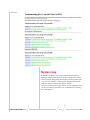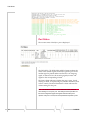
1
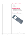
RJ-11 IP Gateway
User Guide
2120028
Rev 3.0 B
Important Notice
Due to the nature of wireless communications, transmission and reception of data can never be guaranteed. Data may be delayed, corrupted (i.e., have errors) or be totally lost. Although significant delays or losses of data are rare when wireless devices such as the Sierra Wireless AirLink Product Name are used in a normal manner with a well‐constructed network, the Sierra Wireless AirLink Product Name should not be used in situations where failure to transmit or receive data could result in damage of any kind to the user or any other party, including but not limited to personal injury, death, or loss of property. Sierra Wireless accepts no responsibility for damages of any kind resulting from delays or errors in data transmitted or received using the Sierra Wireless AirLink Product Name, or for failure of the Sierra Wireless AirLink Product Name to transmit or receive such data.
Safety and Hazards
Do not operate the Sierra Wireless AirLink Product Name in areas where blasting is in progress, where explosive atmospheres may be present, near medical equipment, near life support equipment, or any equipment which may be susceptible to any form of radio interference. In such areas, the Sierra Wireless AirLink Product Name MUST BE POWERED OFF. The Sierra Wireless AirLink Product Name can transmit signals that could interfere with this equipment.
Do not operate the Sierra Wireless AirLink Product Name in any aircraft, whether the aircraft is on the ground or in flight. In aircraft, the Sierra Wireless AirLink Product Name MUST BE POWERED OFF. When operating, the Sierra Wireless AirLink Product Name can transmit signals that could interfere with various onboard systems.
Note: Some airlines may permit the use of cellular phones while the
aircraft is on the ground and the door is open. Sierra Wireless AirLink
Product Name may be used at this time.
The driver or operator of any vehicle should not operate the Sierra Wireless AirLink Product Name while in control of a vehicle. Doing so will detract from the driver or operatorʹs control and operation of that vehicle. In some states and provinces, operating such communications devices while in control of a vehicle is an offence.
Limitation of
Liability
Rev 3.0 B 2/15/08
The information in this manual is subject to change without notice and does not represent a commitment on the part of Sierra Wireless. SIERRA WIRELESS AND ITS AFFILIATES SPECIFICALLY DISCLAIM LIABILITY FOR ANY AND ALL 1
DIRECT, INDIRECT, SPECIAL, GENERAL, INCIDENTAL, CONSEQUENTIAL, PUNITIVE OR EXEMPLARY DAMAGES INCLUDING, BUT NOT LIMITED TO, LOSS OF PROFITS OR REVENUE OR ANTICIPATED PROFITS OR REVENUE ARISING OUT OF THE USE OR INABILITY TO USE ANY SIERRA WIRELESS PRODUCT, EVEN IF SIERRA WIRELESS AND/OR ITS AFFILIATES HAS BEEN ADVISED OF THE POSSIBILITY OF SUCH DAMAGES OR THEY ARE FORESEEABLE OR FOR CLAIMS BY ANY THIRD PARTY.
Notwithstanding the foregoing, in no event shall Sierra Wireless and/or its affiliates aggregate liability arising under or in connection with the Sierra Wireless product, regardless of the number of events, occurrences, or claims giving rise to liability, be in excess of the price paid by the purchaser for the Sierra Wireless product.
Patents
Portions of this product may be covered by some or all of the following US patents:
5,515,013
5,629,960
5,845,216
5,847,553
5,878,234
5,890,057
5,929,815
6,169,884
6,191,741
6,199,168
6,339,405
6,359,591
6,400,336
6,516,204
6,561,851
6,643,501
6,653,979
6,697,030
6,785,830
6,845,249
6,847,830
6,876,697
6,879,585
6,886,049
6,968,171
6,985,757
7,023,878
7,053,843
7,106,569
7,145,267
7,200,512
D442,170
D459,303
and other patents pending.
Copyright
©February 15, 2008 Sierra Wireless. All rights reserved.
Trademarks
AirCard® and “Heart of the Wireless Machine®” are registered trademarks of Sierra Wireless. Watcher® is a trademark of Sierra Wireless, registered in the European Community. AirLink™ and AceWare™ are trademarks of Sierra Wireless.
Sierra Wireless, the Sierra Wireless logo, the red wave design, and the red‐tipped antenna are trademarks of Sierra Wireless.
Windows® is a registered trademark of Microsoft Corporation.
Other trademarks are the property of the respective owners.
Rev 3.0 B 2/15/08
2
Contact
Information
Support Desk:
Phone: 1-877-231-1144
Hours: 5:00 AM to 5:00 PM Pacific Time,
Monday to Friday, except US Holidays
E-mail: [email protected]
Sales Desk:
Phone: 1-510-781-4200
1-604-232-1488
Hours: 8:00 AM to 5:00 PM Pacific Time
E-mail: [email protected]
Post: Sierra Wireless AirLink Solutions
3159 Corporate Place
Hayward, CA
USA
94545
Sierra Wireless
13811 Wireless Way
Richmond, BC
Canada
V6V 3A4
Fax: 1-510-781-4299
1-604-231-1109
Web: www.sierrawireless.com
Consult our website for up‐to‐date product descriptions, documentation, application notes, firmware upgrades, trouble‐
shooting tips, and press releases:
www.sierrawireless.com
Rev 3.0 B 2/15/08
3
Contents
Introduction . . . . . . . . . . . . . . . . . . . . . . . . . . . . . . . . . . . . . . . . . . . . . . . . . . . . . . . . .3
RJ-11 IP Gateway Features . . . . . . . . . . . . . . . . . . . . . . . . . . . . . . . . . . . . . . . . . . . . . . . . . . . . . . . . . . . . 4
Quick Start . . . . . . . . . . . . . . . . . . . . . . . . . . . . . . . . . . . . . . . . . . . . . . . . . . . . . . . . . .5
Before You Start . . . . . . . . . . . . . . . . . . . . . . . . . . . . . . . . . . . . . . . . . . . . . . . . . . . . . . . . . . . . . . . . 5
Software Required . . . . . . . . . . . . . . . . . . . . . . . . . . . . . . . . . . . . . . . . . . . . . . . . . . . . . . . . . . . . . . . . . . . . 5
Hardware Required . . . . . . . . . . . . . . . . . . . . . . . . . . . . . . . . . . . . . . . . . . . . . . . . . . . . . . . . . . . . . . . . . . . 5
Cellular Account Required . . . . . . . . . . . . . . . . . . . . . . . . . . . . . . . . . . . . . . . . . . . . . . . . . . . . . . . . . . . . . 6
Important Information about Ports . . . . . . . . . . . . . . . . . . . . . . . . . . . . . . . . . . . . . . . . . . . . . . . . . . . . . . 6
Configuring your Raven X for the RJ-11 IP Gateway . . . . . . . . . . . . . . . . . . . . . . . . . . . . . . . . . . 6
Default settings . . . . . . . . . . . . . . . . . . . . . . . . . . . . . . . . . . . . . . . . . . . . . . . . . . . . . . . . . . . . . . . . . . . . . . . 6
Configuring the Raven X. . . . . . . . . . . . . . . . . . . . . . . . . . . . . . . . . . . . . . . . . . . . . . . . . . . . . . . . . . 7
Configuring the IP Address and Interface Port of the RJ-11 RJ-11 IP Gateway Defaults. . . . 9
Configuring the RJ-11 IP Gateway . . . . . . . . . . . . . . . . . . . . . . . . . . . . . . . . . . . . . . . . . . . . . . . . . . . . . . . 9
Hardware Setup . . . . . . . . . . . . . . . . . . . . . . . . . . . . . . . . . . . . . . . . . . . . . . . . . . . .15
Connectors and Reset button . . . . . . . . . . . . . . . . . . . . . . . . . . . . . . . . . . . . . . . . . . . . . . . . . . . . 15
Status LEDs . . . . . . . . . . . . . . . . . . . . . . . . . . . . . . . . . . . . . . . . . . . . . . . . . . . . . . . . . . . . . . . . . . . 16
Specifications . . . . . . . . . . . . . . . . . . . . . . . . . . . . . . . . . . . . . . . . . . . . . . . . . . . . . 19
Physical Dimensions . . . . . . . . . . . . . . . . . . . . . . . . . . . . . . . . . . . . . . . . . . . . . . . . . . . . . . . . . . . . . . . . 19
Connections . . . . . . . . . . . . . . . . . . . . . . . . . . . . . . . . . . . . . . . . . . . . . . . . . . . . . . . . . . . . . . . . . . . . . . . . 19
Phone and Modem standards . . . . . . . . . . . . . . . . . . . . . . . . . . . . . . . . . . . . . . . . . . . . . . . . . . . . . . . . . 20
Environmental Conditions . . . . . . . . . . . . . . . . . . . . . . . . . . . . . . . . . . . . . . . . . . . . . . . . . . . . . . . . . . . . 20
Optional Mounting Bracket . . . . . . . . . . . . . . . . . . . . . . . . . . . . . . . . . . . . . . . . . . . . . . . . . . . . . . . . . . . . 20
Web Interface . . . . . . . . . . . . . . . . . . . . . . . . . . . . . . . . . . . . . . . . . . . . . . . . . . . . . .23
Web-based Interface . . . . . . . . . . . . . . . . . . . . . . . . . . . . . . . . . . . . . . . . . . . . . . . . . . . . . . . . . . . 23
Welcome . . . . . . . . . . . . . . . . . . . . . . . . . . . . . . . . . . . . . . . . . . . . . . . . . . . . . . . . . . . . . . . . . . . . . . . . . . . 24
Serial Settings . . . . . . . . . . . . . . . . . . . . . . . . . . . . . . . . . . . . . . . . . . . . . . . . . . . . . . . . . . . . . . . . . . . . . . 25
Port Services . . . . . . . . . . . . . . . . . . . . . . . . . . . . . . . . . . . . . . . . . . . . . . . . . . . . . . . . . . . . . . . . . . . . . . . 26
Network Translation . . . . . . . . . . . . . . . . . . . . . . . . . . . . . . . . . . . . . . . . . . . . . . . . . . . . . . . . . . . . . . . . . . 28
Protocol Settings . . . . . . . . . . . . . . . . . . . . . . . . . . . . . . . . . . . . . . . . . . . . . . . . . . . . . . . . . . . . . . . . . . . . 29
Rev 3.0 B 2/15/08
1
Contents
Network Configuration . . . . . . . . . . . . . . . . . . . . . . . . . . . . . . . . . . . . . . . . . . . . . . . . . . . . . . . . . . 30
Network Settings . . . . . . . . . . . . . . . . . . . . . . . . . . . . . . . . . . . . . . . . . . . . . . . . . . . . . . . . . . . . . . . . . . . . 30
DNS Settings . . . . . . . . . . . . . . . . . . . . . . . . . . . . . . . . . . . . . . . . . . . . . . . . . . . . . . . . . . . . . . . . . . . . . . . 32
IP Routing . . . . . . . . . . . . . . . . . . . . . . . . . . . . . . . . . . . . . . . . . . . . . . . . . . . . . . . . . . . . . . . . . . . . . . . . . . 33
Time Settings . . . . . . . . . . . . . . . . . . . . . . . . . . . . . . . . . . . . . . . . . . . . . . . . . . . . . . . . . . . . . . . . . . . . . . . 35
Security Settings . . . . . . . . . . . . . . . . . . . . . . . . . . . . . . . . . . . . . . . . . . . . . . . . . . . . . . . . . . . . . . . 36
Online Update . . . . . . . . . . . . . . . . . . . . . . . . . . . . . . . . . . . . . . . . . . . . . . . . . . . . . . . . . . . . . . . . . . . . . . . 38
Status and Logs . . . . . . . . . . . . . . . . . . . . . . . . . . . . . . . . . . . . . . . . . . . . . . . . . . . . . . . . . . . . . . . . 40
Troubleshooting . . . . . . . . . . . . . . . . . . . . . . . . . . . . . . . . . . . . . . . . . . . . . . . . . . . . . . . . . . . . . . . . . . . . . 40
System Log . . . . . . . . . . . . . . . . . . . . . . . . . . . . . . . . . . . . . . . . . . . . . . . . . . . . . . . . . . . . . . . . . . . . 41
Port Status . . . . . . . . . . . . . . . . . . . . . . . . . . . . . . . . . . . . . . . . . . . . . . . . . . . . . . . . . . . . . . . . . . . . . . . . . . 42
OS and Network Information . . . . . . . . . . . . . . . . . . . . . . . . . . . . . . . . . . . . . . . . . . . . . . . . . . . . . . . . . . 43
Log Files and Settings . . . . . . . . . . . . . . . . . . . . . . . . . . . . . . . . . . . . . . . . . . . . . . . . . . . . . . . . . . . . . . . . 43
Commands . . . . . . . . . . . . . . . . . . . . . . . . . . . . . . . . . . . . . . . . . . . . . . . . . . . . . . . . . . . . . . . . . . . . 45
Ping . . . . . . . . . . . . . . . . . . . . . . . . . . . . . . . . . . . . . . . . . . . . . . . . . . . . . . . . . . . . . . . . . . . . . . . . . . . . . . . . 45
Reset/Reboot . . . . . . . . . . . . . . . . . . . . . . . . . . . . . . . . . . . . . . . . . . . . . . . . . . . . . . . . . . . . . . . . . . 46
AT Commands . . . . . . . . . . . . . . . . . . . . . . . . . . . . . . . . . . . . . . . . . . . . . . . . . . . . 49
S-Registers . . . . . . . . . . . . . . . . . . . . . . . . . . . . . . . . . . . . . . . . . . . . . . . . . . . . . . . . . . . . . . . . . . . . 51
Response Codes . . . . . . . . . . . . . . . . . . . . . . . . . . . . . . . . . . . . . . . . . . . . . . . . . . . . . . . . . . . . . . . . . . . . . 51
Modem Signal Behavior . . . . . . . . . . . . . . . . . . . . . . . . . . . . . . . . . . . . . . . . . . . . . . . . . . . . . . . . . . . . . . 52
Phone Numbers . . . . . . . . . . . . . . . . . . . . . . . . . . . . . . . . . . . . . . . . . . . . . . . . . . . . . . . . . . . . . . . . . . . . . 53
Port Settings . . . . . . . . . . . . . . . . . . . . . . . . . . . . . . . . . . . . . . . . . . . . . . . . . . . . . . . . . . . . . . . . . . . . . . . 54
Rev 3.0 B 2/15/08
2
1: Introduction
• RJ-11 IP Gateway
Features
Many existing meters, data loggers, RTUʹs, PLCʹs, point‐of‐
sale, and other remote devices only have physical interfaces designed to access the telephone network. They do not have serial or Ethernet ports. They currently use analog cellular or standard phone lines to connect in circuit‐switched mode for data transfer.
Analog cellular phone service is being discontinued. The combination of the RJ‐11 IP Gateway and a Sierra Wireless AirLink Raven with Ethernet port, enables remote connectivity between host applications and these remote devices over cellular packet data networks. The RJ‐11 IP Gateway provides the bridge between a device requiring an RJ‐11 interface and the Raven, with its Ethernet interface. Figure 1-1: RJ-11 IP Gateway with an AirLink Raven-E
Rev 3.0 B 2/15/08
3
DocTitleHeader
Figure 1-2: RJ-11 Gateway with an AirLink Raven-E and a Modem Router
RJ-11 IP Gateway Features
•
One RJ‐11 phone port
The phone port is a phone line designed to function just like standard wall‐jack analog phone line. It is designed primarily to connect dial‐up devices, with internal modems, to the RJ‐11 IP Gateway, which then routes data from the devices over the network. The RJ‐11 IP Gateway mimics the phone company, answering incoming calls and routing them to an internal modem attached to the phone port, or generating calls from an internal modem to an attached device.
Caution: The RJ-11 IP Gateway's RJ-11 phone port should never be
connected into the Public Switched Telephone Network (PSTN). This
device is designed to emulate the PSTN for other devices. The RJ-11
IP Gateway may sustain damage not covered by warranty if it is
connected to the Public Switched Telephone Network.
•
One RJ‐45 auto‐sensing 10base‐T Ethernet port
The Ethernet port is designed to be connected to either an AirLink modem with an Ethernet port such as the Raven‐E or Raven X . With the modem connected to the cellular network, the communication from the device connected to the RJ‐11 port can be routed to the Internet and your remote host.
•
One power connector
The RJ‐11 IP Gateway uses a DC AC power adapter with an optional AC DC adapter available.
•
Status LEDs
The RJ‐11 IP Gateway status LEDs give clear and concise information about the operation of the ports.
4
2120028
2: Quick Start
• Before You Start
• Configuring the Raven
X
• Configuring the IP
Address and
Interface Port of the
RJ-11 RJ-11 IP
Gateway Defaults
Configuring the RJ‐11 IP Gateway to work with your Sierra Wireless Airlink Raven X and vice‐versa is easy. This chapter covers a basic configuration. For more advanced configuration of your Raven X, refer to the modem’s user guide. The complete configuration options for the RJ‐11 IP Gateway are in this guide.
Before You Start
Software Required
•
AceManager ‐ Graphical interface for configuring your Sierra Wireless AirLink modem. AceManager is located on all modem the CDs or you can download AceManager from the Sierra Wireless website: http://
www.sierrawireless.com. A default installation of this utility is assumed later in these directions.
Hardware Required
•
Ethernet Cable ‐ The RJ‐11 IP Gateway and Raven X have an auto‐sensing Ethernet port, you can use either a cross‐
over cable or a straight‐through Ethernet cable. •
Power adapters and a power source ‐ You will need a power adapter and power source for both the RJ‐11 IP Gateway and the RavenX.
Note: If you are using a Raven-E, you may need a cross-over cable
to connect to the RJ-11 IP Gateway.
•
Rev 3.0 B 2/15/08
PC or Laptop ‐ To configure both the RJ‐11 IP Gateway and the device, you will need a computer with Internet Access, other than the cellular account, and an available Ethernet port.
5
DocTitleHeader
Cellular Account Required
•
Cellular Account ‐ To use this guide, you need to already have an active account with a cellular provider and to have activated your modem with that provider. Sierra Wireless AirLink modems are certified to work with a variety of cellular providers.
Tip: If you need to activate your modem, you can use the Setup
Wizard for your cellular provider which you can obtain from the Sierra
Wireless website:
http://
www.sierrawireless.com.
Important Information about Ports
•
Port Blocking ‐ Many cellular providers and other ISPs block ports below 1024 which are the default ports for many server protocols (such as HTTP, telnet, and SSH). If your provider blocks these ports, you will need to configure ports you can access.
Configuring your Raven X for
the RJ-11 IP Gateway
Note: While this guide application note covers installing an RJ-11 IP
Gateway with a Raven X, the RJ-11 IP Gateway is also designed to
work with the Raven-E and any other Airlink modem with an Ethernet
connection, using the same configuration outlined here
These steps are just a basic configuration to get you started and allow the Raven X to connect with the RJ‐11 IP Gateway. Refer to the user guide for more configuration options for specific environments. Note: Omit this section if you are
not connecting your Host RJ-11
IP Gateway to a Raven X.
6
Default settings
•
Management Interface IP Address: 192.168.13.31.
•
Telnet and Wireless Ace password: 12345
•
DHCP server: enabled.
•
Public Mode ‐ the IP Address assigned by the carrier is assigned to the RJ‐11 IP Gateway.
2120028
Note: If you are using the defaults for the Raven X and the RJ-11 IP
Gateway, you can skip this section and connect your RJ-11 IP
Gateway directly to your Raven X.
Configuring the Raven X
1.
Connect your Raven X directly to the Ethernet port on your computer and to power. 2.
Start Wireless Ace and connect to your modem. Start > All Programs > AirLink Communications > Wireless Ace 3G > Wireless Ace 3G
a. Click on Connect.
b. Select UDP.
c.
Type in the modem’s local IP (default is 192.168.13.31).
d. Type in the modem’s password (default 12345)
Figure 2-1: Wireless Ace : Connexion Connect
3.
Select Common > PPP/Ethernet from the menu on the left side of Wireless Ace (under “Groups”). Configure the Raven X for Public Mode. Set the *HOSTPRIVMODE to 0. In this mode, the modem assigns the RJ‐11 IP Gateway the IP address it has received from your cellular provider. This is the default setting for the modem. 0 - Use Public IP
Rev 3.0 B 2/15/08
7
DocTitleHeader
Figure 2-2: Wireless Ace : PPP/Ethernet
4.
When you have finished configuring the Ethernet settings, click the Write button on the tool bar of Wireless Ace and wait for the message “Write Successful” to appear in the status bar.
Figure 2-3: Wireless Ace : Write
5.
Note the IP address given to the modem by your cellular provider. a. Select Status from the menu on the left side of Wireless Ace (under “Groups”).
Figure 2-4: Wireless Ace : Status (état)
b. Note the IP address listed in the Value column for the command *NETIP. For *NETSTATE, “Network Ready” means your modem is connected on the cellular network and waiting for connections. “Network Dormant” means the modem is connected and waiting for connections but the connection has been idle. In either state, the modem is ready for the steps in the next section. 6.
8
Disconnect your modem’s Ethernet cable from your computer, but leave the modem connected to power so it remains on the cellular network. 2120028
Configuring the IP Address and Interface
Port of the RJ-11 RJ-11 IP Gateway
Defaults
•
Phone port: 78 data bits, even no parity, and 1 stop bit (7E18N1).
•
Protocol: American/Bell 212A.
•
Maximum baud: 2400.
•
DHCP client: enabled disabled.
If you are using the defaults for the RJ-11 IP Gateway, you can skip
this section and connect your RJ-11 IP Gateway directly to your Raven
X and device and network.
Configuring the RJ-11 IP Gateway
1.
The IP Address configuration is how the RJ‐11 IP Gateway will communicate with the Raven X. Connect the RJ‐11 IP Gateway to power and connect the Ethernet cable from your Raven X computer to the RJ‐11 IP Gateway. Caution: If the modem has been disconnected from power between
the steps of the previous section and this section, it may have a
different IP address than what you noted. You will need to reconnect
the modem to your computer, reconnect Wireless Ace and repeat step
5 above (page 7) to determine the new IP address given to the
modem by the cellular provider
2.
Open your web browser and use the IP address from step 5 above as the web address. Type “http://”, the IP address from the modem, and “192.168.1.3:9080” (see the example in the screenshot below) in the Address or Location bar and press the enter key.
http://166.213.236.221:9080
Figure 2-5: Web Browser : Enter the Location
Rev 3.0 B 2/15/08
9
DocTitleHeader
Note: Since many cellular carriers block the standard web browser
ports (80 and 8080), the RJ-11 IP Gateway uses 9080 by default as
the port for the web-based interface.
The web‐based interface will open. On the left side of the window are menu options. The central area of the window is the working area (shown in the close up screen shots for the configuration settings).
Figure 2-6: RJ-11 IP Gateway Interface
3.
Select Network Settings from the menu on the left. Figure 2-7: Host RJ-11 IP Gateway:Network Settings
10
2120028
In DHCP Mode, the RJ‐11 IP Gateway will receive its IP address from the modem.This is the default configuration for the RJ‐11 IP Gateway. If you are using the default Public Mode settings for the Raven X, use DHCP mode.
The IPv4 Address and the IPv4 Netmask should be listed as 0.0.0.0. (The current IP address and current netmask listed above the entry boxes is received from the modem in DHCP mode. It is for display only.)
Figure 2-8: RJ-11 IP Gateway: Network Interface Settings )
192.168.1.3
255.255.255.0
Figure 2-9: Host RJ-11 IP Gateway: Network Interface Settings
Rev 3.0 B 2/15/08
11
DocTitleHeader
a.
4.
Select Serial Settings from the menu on the left. The Serial Settings page allows you to specify the baud rate, protocol, character size, parity, stop bits, and flow control behavior for the RJ‐11 port (Phone).
Figure 2-10: RJ-11 IP Gateway: Serial Settings
For more information on the serial and other settings, refer to page 17.
Note: For most configurations, the defaults for the other settings are
best. Change these parameters only if you know the device you will
be connecting to the RJ-11 IP Gateway requires special settings.
5.
12
Click on the Reset/Reboot menu option for the IP Address configuration and any changes to the serial port settings to take effect.
2120028
Figure 2-11: RJ-11 IP Gateway: Reset/Reboot
Click the Reboot button to restart the RJ‐11 IP Gateway with the configured settings.
Rev 3.0 B 2/15/08
13
DocTitleHeader
14
2120028
3: Hardware Setup
• Connectors and Reset
button
• Status LEDs
Designed for simplicity, the RJ‐11 IP Gateway hardware has few complicated parts.
Connectors and Reset button
The Reset button is recessed. To reset the connection, using an unbent paperclip or other narrow, blunt tip, press and quickly release the reset button. To reset the configuration to the factory default, press and hold the reset button until you see the appropriate alternating light sequence.
Reset
Power
RJ‐45 Ethernet
Figure 3-1: Right side: RJ-45 connector, Power connector, and Reset button
(not to scale)
RJ‐11
Figure 3-2: Left side: RJ-11(phone) connector (not to scale)
Warning: The RJ-11 IP Gateway's RJ-11 phone
port should never be connected into the Public
Switched Telephone Network (PSTN). This device is
designed to emulate the PSTN for other devices.
Rev 3.0 B 2/15/08
15
Hardware
The RJ-11 IP Gateway may sustain damage not
covered by warranty if it is connected to the Public
Switched Telephone Network.
Status LEDs
The top panel of the RJ‐11 IP Gateway displays the status LEDs. Figure 3-3: RJ-11 IP Gateway Top Panel (not to scale)
•
STATUS ‐ Indicates the overall status of the device
Table 3-1: Status - Normal Operation
LED Condition
16
Description
Blinking Yellow
The RJ-11 IP Gateway is starting up.
Solid Green
The RJ-11 IP Gateway is obtaining an IP
address from the modem.
Blinking Green
The RJ-11 IP Gateway has an IP address
and is operating normally.
Off
No power to the RJ-11 IP Gateway.
2120028
Table 3-2: Status - Resetting the Configuration
LED Condition
Description
Alternating Green/
Red
While the Reset button is held in, the status
light will begin to blink in this sequence to
indicate the RJ-11 IP Gateway will shortly
restore the factory default condition.
If you do not want to restore the factory
default, release the button before the
sequence changes to Green/Yellow.
Alternating Green/
Yellow
While the Reset button is held in, the status
light will begin to blink in this sequence to
indicate the factory default configuration was
restored. Once the RJ-11 IP Gateway
indicates the configuration was restored, you
can release the reset button.
Table 3-3: Status - Error Conditions
LED Condition
Description
Alternating Green/Red
A serious system error occurred. See the
system log for more details.
Alternating Green/
Yellow
The current configuration is corrupt and
the factory default configuration is being
used
Solid Red
The RJ-11 IP Gateway has encountered a
fatal error, contact technical support for
assistance.
ETHERNET ‐ Indicates the status of the Ethernet connection (RJ‐45 port).
•
Table 3-4: Ethernet
LED Condition
Solid Green
The Ethernet link is available and
idle.
Green/Yellow
Blinking
Network traffic is detected.
Off
The Ethernet link is unavailable.
•
Rev 3.0 B 2/15/08
Description
PHONE ‐ Indicates the status of the phone port (RJ‐11).
17
Hardware
Table 3-5: Phone
LED Condition
18
Description
Solid Green
The port is open and idle.
Blinking Green
The port is open, and data is being
transmitted or received. When data is
being continuously transferred, this LED
will blink approximately 2 times per
second.
Blinking Red
Data errors will cause periodic red blinks.
Persistent red blinks may imply a
configuration problem (incorrect baud rate,
parity settings, etc.)
Yellow
Port is closed.
Solid Red
Port hardware has failed.
Off
Power is off.
2120028
A: Specifications
• Physical Dimensions
• Connections
• Phone and Modem
standards
• Phone and Modem
standards
• Environmental
Conditions
• Optional Mounting
Bracket
Physical Dimensions
•
6.6 inches x 2..5 inches x 1.2 inches (168 mm x 64 mm x 30 mm)
•
4.,8 ounces (136 grammes)
•
External 110 to 240 VAC power supply: +7VDC to +36VDC ‐ 300mA at 12V (3.6W)
1. Phone Port: RJ-11
2. Ethernet Port: RJ-45 auto-sensing
10base-T
3
2
3. LEDs: Status, Ethernet, Phone
1
Connections
•
Supports generic (raw) TCP/IP access to phone port without requiring special protocols or processing. Caution: The RJ-11 IP Gateway's RJ-11 phone port should never be
connected into the Public Switched Telephone Network (PSTN). This
device is designed to emulate the PSTN for other devices.
The RJ-11 IP Gateway may sustain damage not covered by warranty
if it is connected to the Public Switched Telephone Network.
Rev 3.0 B 2/15/08
19
Hardware
Phone and Modem standards
•
Bell 212A
•
ITU‐T V.22
•
ITU‐T V.22bis
•
V.22 FastConnect (Hypercom)
Environmental Conditions
•
Operating temperature range: ‐30 to 70°C
•
Storage temperature range: ‐30 to 70°C
•
Humidity range: 10% to 90% non‐condensing
Optional Mounting Bracket
The mounting bracket is designed to “snap” on to the back of the Host RJ‐11 IP Gateway for easy installation.
20
2120028
Figure 1-1: Mounting BracketSupport 100-170-1010
Rev 3.0 B 2/15/08
21
Hardware
22
2120028
2: Web Interface
•
•
•
•
•
•
•
Web-based Interface
Network Configuration
Security Settings
Status and Logs
System Log
Commands
Reset/Reboot
The RJ‐11 IP Gateway can be configured to handle a variety of devices which need to connect to an RJ‐11 port.
Note: For configuration options for your Raven X, refer to the Raven
x’s user guide. All user guides are available on the Sierra Wireless
website: http://www.sierrawireless.com/support.
Web-based Interface
Note: Screen shots in this guide are using Microsoft Internet
Explorer, but you can use any web browser to configure the RJ-11 IP
Gateway.
The RJ‐11 IP Gateway employs a web‐based user interface. To access the web interface, you will need to know the IP Address given to your Raven‐E by the cellular carrier (or the modem domain name if you have configured IP Manager settings for the modem). Type the IP address (or modem domain name) into the Address bar of your web browser followed by “:9080” (see the example below). Note: Since many cellular carriers block the standard web browser
ports (80 and 8080), the RJ-11 IP Gateway uses 9080 by default as a
port for the web-based interface.
Figure 2-1: Web Browser: Enter the Location
Rev 3.0 B 2/15/08
23
Hardware
The web interface for the RJ‐11 IP Gateway, by default, has no security. If you made changes to the security configuration (“Security Settings” on page 24), you will be prompted for a user name and password before the web‐based interface will open.
The menu selections for the configuration interface are on the left side of the window. Figure 2-2: RJ-11 IP Gateway Web Browser-based Interface
Service Configuration
Most of the Service Configuration menu options deal with the RJ‐11 port.
Welcome
The Welcome screen is the first page displayed when you connect to the RJ‐11 IP Gateway. Current settings and status are shown in a table.
24
2120028
Figure 2-3: RJ-11 IP Gateway: Welcome - Device Server Information
•
Ethernet Address : MAC Address of the RJ‐11 IP Gateway. •
IP Address : The current IP Address of the RJ‐11 IP Gateway and how the IP address was assigned (in the example, a Raven‐E in Public Mode used DHCP to give the RJ‐11 IP Gateway the IP addressed assigned by the cellular network). •
IP Netmask : The current subnetmask of the RJ‐11 IP Gateway and how the device obtained it. Serial Settings
•
The Serial Settings page allows you to specify the baud rate, protocol, character size, parity, stop bits, and flow control behavior for the RJ‐11 port (Phone). Note: For most configurations, the default settings (shown in the
screen shots) are best. Change these parameters only if you know the
device you will be connecting to the RJ-11 IP Gateway requires
special settings.
Rev 3.0 B 2/15/08
25
Hardware
Figure 2-4: RJ-11 IP Gateway: Serial Settings
•
Enabling flow control enables it on both input and output.
•
The inactivity time‐out shuts down the service on the port if there is no input or output in the specified time‐out period.
•
With Modem Signal Loopbacks, the RJ‐11 IP Gateway eliminates the use of specialized cables required to change signal types and directions by performing the loopback of signal types to other signal types internally. •
NativeCOM, (or any RFC‐2217 Telnet client with COM‐
PORT‐OPTION support) overrides the baud rate, size, parity, stop bits and flow control parameters.
Port Services
By default, the RJ‐11 port is configured to accept incoming TCP connections from TCP/telnet clients with outgoing service based on phone numbers dialed by the attached device (Modem Service). You may configure the ports to initiate 26
2120028
outgoing raw TCP or telnet connections to remote servers. In addition, the modem emulation feature may be enabled to allow a serial port to mimic a modem interface.
•
When using the modem service on the port, the phone number will be translated to a host/port pair then a TCP connection will be established to the remote host.
•
When using outgoing connections on the port, the settings configured on the Serial Settings page will be applied to the port, and a TCP connection will be established to the remote host.
•
Once connected, data received on the port is sent to the remote server over the network connection and data received on the network connection is sent out the port.
Figure 2-5: RJ-11 IP Gateway: Port Services
Rev 3.0 B 2/15/08
•
No Outgoing Service : Disables outgoing port services on the specified port. Incoming connections are still allowed. All port services options will reset to defaults. •
Modem Service : Enables modem emulation on both the incoming and outgoing network connections. The target peer (specified in the Phone Number Translation table and configured in the Protocol Settings page) determines the type of outgoing connection that will be made. 27
Hardware
•
Outgoing Network Connection : Enables an outgoing connection to the specified host. •
Outgoing Telnet Connection : Enables an outgoing telnet connection to the specified host. •
Modem Service Options : When Modem Service is selected, you may also configure the Source TCP Port. In most cases, the value used for the source port is arbitrary and you can leave this field set to 0 for “any”. However, if your server or firewall has specific requirements you may specify an explicit source port number in the Source TCP Port field. If this port is not available when the TCP service starts up, an error will occur and the TCP service will reset and try again. Network Translation
The RJ‐11 IP Gateway is capable of accepting incoming TCP connections and redirecting them to remote TCP hosts. This functionality is called network translation and behaves much like a TCP “pipe” between two systems. The Host RJ‐11 IP Gateway also uses Network Translation to allow connections to the web‐base interface on a port other than the http protocol defined port of 80 which is frequently blocked by cellular carriers.
Figure 2-6: RJ-11 IP Gateway: Network Tnaslation
It is also possible to modify the network protocol traveling through the TCP pipe by using the Protocol Settings page to define the remote hostʹs protocol requirements. The most 28
2120028
common use for this functionality is to add SSL encryption to an incoming TCP connection prior to sending it along to the remote host.
The Network Translation table is used to define network mappings for TCP pipes. You must first specify the incoming TCP port to which your device or application will connect. Then, you must specify the outgoing hostname and destination TCP port for the TCP pipe.
You can also specify the source TCP port for the outgoing TCP connection. Usually, this should be set to 0 to allow automatic selection of the source port. However, if you have a firewall that imposes limits on source TCP ports then you may need to set this to something specific. Note that if you specify something other than 0, you will be limited to only 1 TCP pipe at‐a‐time for any given destination port.
Protocol Settings
For each host (peer) you will make an outgoing connection to, you need to specify the protocol options used for that host. For each host, select the Host from the “Edit settings for a different peer” selection box. Select “Add a new peer definition” link to add a new host.
Figure 2-7: RJ-11 IP Gateway: Protocol Settings
The hosts are identified by their IP address or Hostname and TCP port. You may also specify wild cards. Specific host names and/or port numbers take precedence over the wild cards. An asterisk for the IP address/hostname (for instance “*:443”) Rev 3.0 B 2/15/08
29
Hardware
means any other host when connecting on port 443. An asterisk for the port number (for instance “host.peer.com:*”) refers to any other port on that host. And a double asterisk (“*:*”) refers to all other hosts.
Network Configuration
The Network Configuration group configures settings for the RJ‐45 Ethernet port.
Network Settings
The Network Settings page allows you to set the IP address, the IP netmask, and the TCP keep‐alive settings.
Every IP address contains two pieces of information: the network number and the host number. A network number is assigned to each local area network and is shared by all the network devices on that network. Each network device, or “host”, is assigned a unique host number. The IP netmask defines which portion of an IP address contains the network number, and which portion contains the host number. The default netmask depends on the “class” of the IP address that you are using.
The RJ‐11 IP Gateway has been designed to work in conjunction with an AirLink Raven X. The IP address for the RJ‐11 IP Gateway and the IP address for the Raven X need to be on the same network. If you need to set a specific IP address for the Raven X and the RJ‐11 IP Gateway, you will need to use Private Mode for the Raven X. Setting Private Mode is covered in the Raven‐E User Guide. 30
2120028
Figure 2-8: Host RJ-11 IP Gateway: Network Interface Settings
TCP keep‐alive is a standard feature of TCP/IP that can be configured to automatically monitor the state of TCP connec‐
tions. If one end of an idle TCP connection is severed (like by a network or power failure), it is possible for the other end to remain open indefinitely. If a network host fails while it has an open TCP connection to one of the device server’s serial ports, that serial port might remain unavailable until it is manually reset.
The optional TCP keep‐alive feature sends special “keep‐alive” packets to the remote TCP host in order to detect the situation where the remote host fails. If a failure is detected, the TCP connection is reset to allow other hosts to access the serial port. To enable TCP keep‐alives on serial‐related network connec‐
tions, enter the total time (in seconds) that you will allow TCP connections to remain idle before resetting them. The first keep‐alive packet will be sent after the connection has been idle for half of this total time. After that, four more TCP keep‐
alive packets will be sent at regular intervals until a TCP response is received from the remote host. If no response is received before the total keep‐alive time runs out, the TCP connection will be reset. Rev 3.0 B 2/15/08
31
Hardware
Caution: Enabling TCP keep-alives will increase the amount of
network traffic on your network. Unless you have a specific need for
this feature, it is best to leave it disabled. If you do enable it, it is best
to make the keep-alive time-out larger to reduce network traffic.
DNS Settings
The DNS Settings page allows you to specify a DNS name for your unit, specify the addresses of DNS servers to resolve names, and to pre‐define some host names. The DNS name and servers can also be derived from a DHCP server.
32
2120028
Figure 2-9: RJ-11 IP Gateway: DNS Settings
If the device server is configured to use DHCP, it will try to get DNS configuration information from the DHCP server. You may also manually set up static DNS entries on this page. Having DNS configured allows you to specify names in place of IP addresses in your configuration.
The DNS Server IP Addresses are used to specify the addresses of one or more machines that can be used to resolve names to IP addresses.
The Static Hosts entries are used to define local host name to IP address mappings.
IP Routing
The IP Routing page lets you configure network routes for accessing remote networks.
Rev 3.0 B 2/15/08
33
Hardware
Figure 2-10: Host RJ-11 IP Gateway: IP Routing
If the device server is configured to use DHCP, it will try to get IP configuration information from the DHCP server. You may also manually set up static routes on this page.
Each IP route consists of a destination IP address, a netmask, and a gateway IP address. Depending on the netmask, the destination IP can specify one of two route types:
34
•
Host route: This is a route to a specific IP host. The netmask is always 255.255.255.255.
•
Network route: This is a route to an IP network. The netmask defines which portion of the destination IP address contains the network number.
2120028
The current routing table is also displayed on this page for your reference.
Time Settings
The Time Settings page allows you to configure NTP or HTTP time‐servers to get the system time from. If you are using SSL for peer verification, the device server must obtain a valid time from an external time‐server to verify the peer.
Time is used in the system and other logs. Having the correct time can help to troubleshoot problems or simply to track occurrences of particular events.
The current time is expressed in UTC (Coordinated Universal Time).
Figure 2-11: Host RJ-11 IP Gateway: Time Settings
Rev 3.0 B 2/15/08
35
Hardware
If the device server is configured to use DHCP, it will try to get NTP server information from the DHCP server. You may also manually set up the addresses on this page. The NTP service uses UDP port 123. If your device server is behind a firewall you may need to allow accesses to this port through the firewall. Adding or changing the NTP server will trigger the Host RJ‐11 IP Gateway to get the time again.
The HTTP server you specify need not be a designated time server – just a reliable server. The device server derives the system time from the HTTP header the server returns. Adding an HTTP server will not automatically trigger getting the time. You must reboot for this to take effect.
Security Settings
The security settings page includes settings for the System Password and Network Isolation.
36
2120028
Figure 2-12: Host RJ-11 IP Gateway: Security Settings
Rev 3.0 B 2/15/08
•
System Password: The Host RJ‐11 IP Gateway’s adminis‐
trative functions can be protected by a system password. By default, no system password is configured. Once a password is set, your web browser will prompt you for the system password whenever you try to access sensitive configuration pages. The browser will ask for a username and password. The username is always “admin”. The password will be what you configured.
•
Network Isolation Configuration: By default, all network services are enabled. However, for security, any or all listening services may be disabled. Unselect any services that you wish to disable. These changes will not take effect until the next reboot.
37
Hardware
Online Update
You may configure your device server to make a connection to an update server and obtain updated software or configuration information from the server or send information to the server. Figure 2-13: RJ-11 IP Gateway: Online Update -top half of the page
38
2120028
To configure updates, first, select the update server to use and the SSL parameters for connecting to it. You may specify both the server name and the path for obtaining the updates. If the server requires HTTP authentication from the device server, specify the username and password to use.
You can schedule the updates to happen periodically, or on every startup, or only when manually selected. The automatic update capability can be used along with Network Isolation to provide a way for the device server to “call out” to get updates if all the incoming connections are disabled.
Figure 2-14: RJ-11 IP Gateway: Online Update - middle of the page
You can configure which items to send to the server or update from the server.
Items to send:
•
Product Data – manufacturing configuration data, error records
•
Configuration Database – current settings on the unit
•
System Log – trace activity
Items to Upload:
Rev 3.0 B 2/15/08
•
Operating Software – the software running in the unit
•
File System – SSL certificates
•
Current Configuration – current settings on the unit
39
Hardware
Figure 2-15: RJ-11 IP Gateway: Online Update - bottom of the page
•
Test Configuration – check to make sure the settings are right and the server is available. This will contact the server and go through the communication necessary to send and receive the files without actually doing so.
•
Update Now – contacts the server and sends and updates the files now.
•
Save Changes – save changes for later.
Status and Logs
The status and log pages display system and operation infor‐
mation.
Troubleshooting
Significant events will be displayed for review. For a more complete report of events, see the system log.
40
2120028
Figure 2-16: RJ-11 IP Gateway: Troubleshooting
System Log
By default, the device server stores informational and error messages in the system log. You can also configure the device server to record debug trace data in this system log buffer (See “Log Files and Settings”). The log file is displayed with color‐
coding to make it easier to spot specific entries.
You can save the System Log to a file to review separately. You can also clear the log, but there is no confirmation on clearing the stored log file.
Rev 3.0 B 2/15/08
41
Hardware
Figure 2-17: RJ-11 IP Gateway: System Log
Port Status
The current status of the RJ‐11 port is displayed.
Figure 2-18: RJ-11 IP Gateway: Port Status
The DCD, RTS, CTS, DTR, DSR, and RI columns indicate the status of the modem signals for the RJ‐11 (phone) port. If the modem signal is present (either asserted if it is an outgoing signal, or detected if it is an incoming signal) its name will appear in the corresponding column.
The State column indicates whether the port is open, closed, waiting for DCD, or experiencing any notable conditions (such as flow control). The Serial Parameters column indicates the current settings for the port.
Note: The Serial Parameters column reflect the actual, real-time
serial settings in use by the port. The settings that are specified via
the serial configuration pages are applied each time the port is
opened. If the port is closed, the serial parameters reported by Port
42
2120028
Status may not necessarily match the settings you configured until the
port is re-opened. Furthermore, some clients (like NativeCOM) can
override the configured settings.
The Input, Output, Parity Errors, Framing Errors, and Overrun Errors columns are tallies of activity on the port. Under each port row is a field indicating the current TCP connection status on the port.
The display will update automatically every few seconds. You can stop the automatic update by selecting “Stop” from your browser. To restart the updating, select “Refresh” or “Reload” from your browser.
OS and Network Information
The OS Information shows the current state of system and application tasks as well as memory usage information.
The Network Information displays the status of network services and current connections. The TCP Sockets section shows current connections and TCP listeners. The UDP Listeners section shows UDP ports that are active.
The Network Interfaces displays the status of the currently active interfaces on the unit. This is similar to the “ipconfig” command on a Windows machine or the “ifconfig” command on a Unix machine. The current routing table is displayed as well.
Log Files and Settings
This page has two parts, Enabling Logging (Log settings) and Emailing Debug information.
By default, the RJ‐11 IP Gateway stores informational and warning messages in the system log. You can also configure the RJ‐11 IP Gateway to save trace data in this system log buffer.
Rev 3.0 B 2/15/08
43
Hardware
Figure 2-19: RJ-11 IP Gateway: Log Settings
Tracing is generally used for troubleshooting problems. You can enable tracing for low‐level serial events and on system services such as HTTP (the web browser interface), DHCP, SDP (Systech Device Protocol ‐ used by Systech utilities to find Systech device servers on the network). For port tracing, you must select both the port (phone) and the events that you want to trace.
You can also select additional log file generation, either a log file for the Ethereal Network Protocol Analyzer or a WAV file for later analysis. Selecting “modem.wav” will record the latest modem negotiation from the RJ‐11 port (from the time it dials until it completes negotiation). For the additional log file generation, you will need to specify an email address for the recipient as well as your own email information.
44
2120028
Figure 2-20: RJ-11 IP Gateway: Emailing Debug Information
The SMTP Server Information is the SMTP (mail host) you will be using to send the debug information. You can usually find the SMTP settings in the email client you use. Not all email hosts will allow relaying through their host.
Commands
The RJ‐11 IP Gateway has some built in commands available.
Ping
You can use the Ping command to test a network connection.
Figure 2-21: Host RJ-11 IP Gateway:Ping
Enter the IP address to Ping or a Hostname and the Number of Pings then press the Ping button. The command will display the results as follows:
Sending 10 PINGs to 209.75.217.6...
Rev 3.0 B 2/15/08
45
Hardware
Response from 209.75.217.6: icmp_seq=0, time=10.0 ms
Response from 209.75.217.6: icmp_seq=1, time=10.0 ms
Response from 209.75.217.6: icmp_seq=2, time=10.0 ms
Response from 209.75.217.6: icmp_seq=3, time=10.0 ms
Response from 209.75.217.6: icmp_seq=4, time=10.0 ms
Response from 209.75.217.6: icmp_seq=5, time=10.0 ms
Response from 209.75.217.6: icmp_seq=6, time=10.0 ms
Response from 209.75.217.6: icmp_seq=7, time=10.0 ms
Response from 209.75.217.6: icmp_seq=8, time=10.0 ms
Response from 209.75.217.6: icmp_seq=9, time=10.0 ms
10 packet(s) transmitted, 10 packet(s) received, 0% packet loss.
Not all hosts accept ICMP pings even if they are present on the network. However, the ping command can serve two functions: 1) to test your general network settings – IP address, network mask, gateway and DNS server and 2) whether the device server can reach a given host. Simply resolving a name to an IP address effectively tests the first function.
Note: Some cellular carriers block ICMP pings on their cellular
network.
Reset/Reboot
The Reset/Reboot page lets you reset the phone (RJ‐11) port or the entire RJ‐11 IP Gateway.
46
2120028
Figure 2-22: RJ-11 IP Gateway: Reset/Reboot
You can reset the phone port by selecting the port and pressing the Reset Port(s) button. This will kill whatever service was on the port and reset it back to the current configuration settings.
You may reboot the entire device by pressing the Reboot button. This is the equivalent of power cycling the unit.
Rev 3.0 B 2/15/08
47
Hardware
48
2120028
C: AT Commands
• Response Codes
• Modem Signal
Behavior
• Phone Numbers
• Port Settings
In addition to the web‐based interface, you can use some typed AT Commands with the RJ‐11 IP Gateway. To enter AT commands, you need to be connected to the device via telnet or by using the RJ‐11 port as you would a standard analog modem.
All AT command strings, with the exception of the break sequence (“+++”) and the repeat command (“A/”), must be terminated with the command line termination character, defined in S3 (default is CR). All characters before ʹATʹ are ignored. Unsupported commands are ignored and generate an “OK” result code. Multiple commands may be combined on a single line, however the AT command string is currently limited to 40 characters. Command
Function
Response
/
Repeat last command
Varies
Note: Command executes upon “/” character,
CR not needed.
<blank>
Attention
OK(0)
A
Answer
OK(0), NO CARRIER(3)
D
Dial
CONNECT(1), NO CARRIER(3)
If suffixed with “;” character, will return to
command mode upon connection.
En
Echo Mode
OK(0)
0=Turn command echo off
1=Turn command echo on (default)
Hn
Hang-up or Terminate connection.
Optional argument has no function
OK(0)
In
Information
0=Serial Port Speed
3= Model and Version
Varies
Actual value equals current port speed
NDS/5102 (2 Port, RJ-45) v01A
O
Return to data mode from
command mode
Rev 3.0 B 2/15/08
49
Hardware
Command
Qn
50
Function
Result Codes
0=Enable result codes (default)
1=Supress result codes
Sn=mm
Sn?
Set register to specified value
Return current value formatted as 3
digit decimal
Vn
Result Code Format
0=Numerical result codes
1=Verbose result codes (default)
Response
OK(0)
<blank>
OK(0)
Varies
0
OK
Xn
Result Code Format
0=“CONNECT” upon entering
online data state
1-4=“CONNECT <text>” upon
entering online data state
OK(0)
Zn
Load factory default settings
OK(0)
&Cn
DCD Control
0=DCD always on
1=DCD follows connection status
OK(0)
&Dn
DTR Control
0=ignore
1=loss of DTR switches to
command mode and leaves
connection open
2=loss of DTR switches to
command mode and closes
connection (default)
OK(0)
&F
&Fn
Load factory default settings
OK(0)
Equivalent to ATZ without dropping the
connection. This command does not affect the
flash configuration for the port.
&V
&V0
Display S-register values
Example:
E0 Q1 V0 &C1 &D2
S00:002 S02:043 S03:013 S04:010 S05:008
&V1
Status
Returns reason for the last disconnect:
TERMINATION REASON......DTR LOSS
TERMINATION REASON….CARRIER LOSS
&W
&W1
Write current configuration to flash
OK(0)
&Xnnn
Change baud rate.
nnn
Baud
3
300
12
1,200
24
2,400
48
4,800
96
9,600
14
14,400
OK(0)
2120028
Command
Function
Response
&X
Any other & command is ignored
OK(0)
%X
Any % command is ignored
OK(0)
+X
Any + command is ignored
OK(0)
$Xn
Any $ command is ignored
including 0 or more digits after the
command.
OK(0)
S-Registers
S Registers are 1 byte, volatile registers used to store configu‐
ration data. They are reset to the default state whenever modem emulation is enabled, or the ATZ/AT&F command is received. They can be saved to flash memory with the AT&W command. When the port is opened, the saved parameters are applied to the port.
Register
Contents
Default
S0
Automatic Answer(# of RING's)
0 (disabled)
S1
Number of RING's Received
0
S3
Command Line Termination Character
CR(13)
S4
Response Formatting Character
LF(10)
S5
Command Line Editing Character
BS(08)
S12
Guard time on either side of the +++ sequence to
break into command mode. Specified in 50ths of a
second.
50
Response Codes
Result Code
(ATV1)
Rev 3.0 B 2/15/08
Numeric (ATV0)
Reason
OK
0
Command Successful
CONNECT
1
Connection Established
RING
2
Incoming connection
awaiting answer
NO CARRIER
3
Connection Terminated
51
Hardware
Result Code
(ATV1)
Numeric (ATV0)
Reason
ERROR
4
Error in AT command
string
CONNECT 1200
5
Connected – Serial Port
Speed is 1200 baud
NO DIALTONE
6
Not Used
BUSY
7
Not Used
NO ANSWER
8
Not Used
CONNECT 2400
10
Connected – Serial Port
Speed is 2400 baud
CONNECT 4800
11
Connected – Serial Port
Speed is 4800 baud
CONNECT 9600
12
Connected – Serial Port
Speed is 9600 baud
CONNECT 14400
13
Connected – Serial Port
Speed is 14400 baud
Modem Signal Behavior
The RJ‐11 IP Gateway is not a modem (DCE), but is a terminal (DTE) device. It is designed to be connected to another DTE device via RJ‐11 cable.The RI (Ring Indicator) signal does not have a corresponding outgoing signal so it is not supported.
Specifically, the DTR, DSR and DCD signals should be crossed with the device as follows: Device
RJ-11 IP Gateway
DCD,DSR
DTR
DTR
DCD,DSR
To emulate a modem properly, the Host RJ‐11 IP Gateway does the following: :
52
2120028
Mode
Modem DCD Settings
Behavior
Command/Data
Always on (&C0)
DTR is asserted
Command/Data
Follow connection (&C1)
DTR is asserted only when TCP/IP
connection is present and has been accepted
via ATA or auto-answer. DTR is de-asserted
when connection is lost
The device server monitors its DCD signal in order to detect changes in the deviceʹs DTR signal. The following behaviors occur on loss of DCD only. .
Mode
Modem DTR Settings
Response to loss of DCD
Offline
AT&D0
Ignore
Offline
AT&D1
Ignore
Offline
AT&D2
Ignore
Online
AT&D0
Ignore
Online
AT&D1
Drop to command mode, preserving connection
Online
AT&D2
Drop to command mode, terminating any
connection
Phone Numbers
The “phone number” used in an outgoing connection for an “ATD” command may be a real phone number that is trans‐
lated to an IP/port pair (see Phone Number Translation) or it consists of an IP address and optional port number. All leading non‐numeric characters (such as the T or P dial modifiers) are ignored. A number of formats are accepted for the “IP” phone number.
Format
Example
Notes
Dotted decimal
a.b.c.d or 192.168.1.1
Numbers are from 0 to 255
Comma decimal
a,b,c,d or 192,168,1,1
For programs that don't allow dots in phone
numbers
Rev 3.0 B 2/15/08
53
Hardware
Format
Example
Notes
Fixed format
aaabbbcccddd or
192168001001
12 digit IP address, each number is three
decimal digits with leading zeroes
Optional port
number
:xxxxx
Decimal TCP port number from 0..65535
•
If no phone number (IP address) is specified, the Desti‐
nation IP Address configured for the port is used.
•
If no port number is specified, the Destination TCP Port configured for the port is used.
•
The source port for the TCP connection follows the Source TCP Port configured for the port.
Port Settings
Most of the serial port settings (like baud rate) are controlled by the configured port settings on the device server. Modem emulation does not support changing these from AT commands.
54
2120028