1
Coriolis flowmeters
SITRANS F C MASS 2100 Di 3-40
Operating Instructions • 07/2010
SITRANS F
SITRANS F
Coriolis Flowmeters
SITRANS F C MASS 2100 Di 3-40
Introduction
1
Safety notes
2
Description
3
Installing/Mounting
4
Connecting
5
Commissioning
6
Service and maintenance
7
Technical data
8
Appendix
A
Operating Instructions
Coriolis flow sensor type MASS 2100 Di 3, 6, 15, 25
or 40 designed for use with transmitter types
SITRANS F C MASS 6000 or SIFLOW FC070
07/2010
A5E02896535-01
Legal information
Warning notice system
This manual contains notices you have to observe in order to ensure your personal safety, as well as to prevent
damage to property. The notices referring to your personal safety are highlighted in the manual by a safety alert
symbol, notices referring only to property damage have no safety alert symbol. These notices shown below are
graded according to the degree of danger.
DANGER
indicates that death or severe personal injury will result if proper precautions are not taken.
WARNING
indicates that death or severe personal injury may result if proper precautions are not taken.
CAUTION
with a safety alert symbol, indicates that minor personal injury can result if proper precautions are not taken.
CAUTION
without a safety alert symbol, indicates that property damage can result if proper precautions are not taken.
NOTICE
indicates that an unintended result or situation can occur if the corresponding information is not taken into
account.
If more than one degree of danger is present, the warning notice representing the highest degree of danger will
be used. A notice warning of injury to persons with a safety alert symbol may also include a warning relating to
property damage.
Qualified Personnel
The product/system described in this documentation may be operated only by personnel qualified for the specific
task in accordance with the relevant documentation for the specific task, in particular its warning notices and
safety instructions. Qualified personnel are those who, based on their training and experience, are capable of
identifying risks and avoiding potential hazards when working with these products/systems.
Proper use of Siemens products
Note the following:
WARNING
Siemens products may only be used for the applications described in the catalog and in the relevant technical
documentation. If products and components from other manufacturers are used, these must be recommended
or approved by Siemens. Proper transport, storage, installation, assembly, commissioning, operation and
maintenance are required to ensure that the products operate safely and without any problems. The permissible
ambient conditions must be adhered to. The information in the relevant documentation must be observed.
Trademarks
All names identified by ® are registered trademarks of the Siemens AG. The remaining trademarks in this
publication may be trademarks whose use by third parties for their own purposes could violate the rights of the
owner.
Disclaimer of Liability
We have reviewed the contents of this publication to ensure consistency with the hardware and software
described. Since variance cannot be precluded entirely, we cannot guarantee full consistency. However, the
information in this publication is reviewed regularly and any necessary corrections are included in subsequent
editions.
Siemens AG
Industry Sector
Postfach 48 48
90026 NÜRNBERG
GERMANY
order number: A5E02896535
Ⓟ 08/2010
Copyright © Siemens AG 2010.
Technical data subject to change
Table of contents
1
2
3
4
5
6
Introduction................................................................................................................................................ 5
1.1
Items supplied ................................................................................................................................5
1.2
History ............................................................................................................................................6
1.3
Further Information ........................................................................................................................6
Safety notes............................................................................................................................................... 9
2.1
Laws and directives .......................................................................................................................9
2.2
Installation in hazardous area ......................................................................................................10
Description............................................................................................................................................... 13
3.1
Design ..........................................................................................................................................13
3.2
Theory of operation......................................................................................................................15
Installing/Mounting................................................................................................................................... 17
4.1
Installation safety precautions......................................................................................................17
4.2
Determining a location .................................................................................................................18
4.3
Orienting the sensor.....................................................................................................................19
4.4
Mounting the sensor ....................................................................................................................21
4.5
Mounting a pressure guard ..........................................................................................................22
Connecting .............................................................................................................................................. 23
5.1
Safety precautions .......................................................................................................................23
5.2
Wiring ...........................................................................................................................................24
5.3
Turning the terminal box ..............................................................................................................25
Commissioning ........................................................................................................................................ 27
6.1
7
8
Zero point adjustment ..................................................................................................................27
Service and maintenance ........................................................................................................................ 29
7.1
Maintenance.................................................................................................................................29
7.2
Transportation/storage.................................................................................................................29
7.3
Recalibration ................................................................................................................................29
7.4
Unit repair.....................................................................................................................................30
7.5
Technical support.........................................................................................................................30
7.6
Return procedures .......................................................................................................................31
Technical data ......................................................................................................................................... 33
8.1
Technical specifications ...............................................................................................................33
8.2
Measurement range.....................................................................................................................34
SITRANS F C MASS 2100 Di 3-40
Operating Instructions, 07/2010, SFIDK.PS.028.Z1.02
3
Table of contents
A
8.3
Accuracy specifications............................................................................................................... 35
8.4
Pressure drop.............................................................................................................................. 36
8.5
Pressure / temperature range ..................................................................................................... 38
8.6
Electrical connection schematics ................................................................................................ 41
8.7
Dimensions and weight ............................................................................................................... 42
Appendix.................................................................................................................................................. 47
A.1
Ordering ...................................................................................................................................... 47
Glossary .................................................................................................................................................. 49
Index........................................................................................................................................................ 53
4
SITRANS F C MASS 2100 Di 3-40
Operating Instructions, 07/2010, SFIDK.PS.028.Z1.02
1
Introduction
These instructions contain all the information you need for using the device.
The instructions are aimed at persons mechanically installing the device, connecting it
electronically, configuring the parameters and commissioning it as well as service and
maintenance engineers.
Note
It is the responsibility of the customer that the instructions and directions provided in the
manual are read, understood and followed by the relevant personnel before installing the
device.
1.1
Items supplied
•
•
•
•
•
MASS 2100 sensor
Sensorprom
Calibration report
Quick Start
SITRANS F technical literature CD-ROM
Inspection
1. Check for visual mechanical damage due to possible improper handling during shipment.
All claims for damage are to be made promptly to the carrier.
2. Make sure the scope of delivery, and the information on the type plate corresponds to
your order and the delivery note.
SITRANS F C MASS 2100 Di 3-40
Operating Instructions, 07/2010, SFIDK.PS.028.Z1.02
5
Introduction
1.2 History
Identification
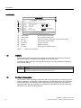
6,75$16)&0$66
&RGH1R
;;;;;;;;;;;;;;;;
;;;;;;;;;;;;;;;;;;;;;;;;;;;;;;;;;;;;;;;;;;
6HULDO1R
'131
0(;;;;;;;;;1::<
;;;;;;;;;;;;
37<HDU
;;EDU;;
&RQQHFWLRQ ;;;;;;;;;;
0DWHULDO
;;;;;O
&DO)DFWRU ;;;;;;;;;;;
7PHGLDrWRr&,3,3
(1FDWHJRU\,,
,,*
'(0.2$7(;;
([LD,,&77
6HQVRUW,QWULQVLFVDIHW\VSHFLILFDWLRQ
6((0$18$/55
7(&+1,&$/'$7$,17(5)$&('$7$
6LHPHQV$6)ORZ,QWUXPHQWV
0DGHLQ'HQPDUN1RUGERUJYHM1RUGERUJ
①
②
③
④
⑤
⑥
⑦
Code number
Serial number
Device specific serial number
DN / PN
Process connector nominal size / sensor pressure rating
PT / Year
Test pressure and time stamp
Connection
Process connector
Material
Material of the pipe
Cal. factor
Device specific calibration factor
Figure 1-1
1.2
Device specific code number
MASS 2100 Type plate
History
The contents of these instructions are regularly reviewed and corrections are included in
subsequent editions. We welcome all suggestions for improvement.
The following table shows the most important changes in the documentation compared to
each previous edition.
Edition
Remarks
07/2010
First edition of Operating Instructions for SITRANS F C MASS 2100 DN 3-40.
The document replaces all previous Instructions for use.
1.3
Further Information
The contents of these Operating Instructions shall not become part of or modify any prior or
existing agreement, commitment or legal relationship. All obligations on the part of Siemens
AG are contained in the respective sales contract which also contains the complete and
solely applicable warranty conditions. Any statements contained herein do not create new
warranties or modify the existing warranty.
6
SITRANS F C MASS 2100 Di 3-40
Operating Instructions, 07/2010, SFIDK.PS.028.Z1.02
Introduction
1.3 Further Information
Product information on the Internet
The Operating Instructions are available on the CD-ROM shipped with the device, and on
the Internet on the Siemens homepage, where further information on the range of SITRANS
F flowmeters may also be found:
Product information on the internet (http://www.siemens.com/flowdocumentation)
Worldwide contact person
If you need more information or have particular problems not covered sufficiently by the
operating instructions, please get in touch with your contact person. You can find contact
information for your local contact person on the Internet:
Local contact person (http://www.automation.siemens.com/partner)
See also
Technical support (Page 30)
SITRANS F C MASS 2100 Di 3-40
Operating Instructions, 07/2010, SFIDK.PS.028.Z1.02
7
Introduction
1.3 Further Information
8
SITRANS F C MASS 2100 Di 3-40
Operating Instructions, 07/2010, SFIDK.PS.028.Z1.02
2
Safety notes
CAUTION
Correct, reliable operation of the product requires proper transport, storage, positioning and
assembly as well as careful operation and maintenance. Only qualified personnel should
install or operate this instrument.
Note
Alterations to the product, including opening or improper repairs of the product, are not
permitted.
If this requirement is not observed, the CE mark and the manufacturer's warranty will expire.
2.1
Laws and directives
General requirements
Installation of the equipment must comply with national regulations. For example EN 6007914 for the European Community.
Instrument safety standards
The device has been tested at the factory, based on the safety requirements. In order to
maintain this condition over the expected life of the device the requirements described in
these Operating Instructions must be observed.
CAUTION
Material compatibility
Siemens Flow Instruments can provide assistance with the selection of wetted sensor
parts. However, the full responsibility for the selection rests with the customer and Siemens
Flow Instruments can take no responsibility for any failure due to material incompatibility.
CE marked equipment
The CE-mark symbolizes the compliance of the device with the following guidelines:
● EMC-directive 2004/108/EC
● Low voltage directive 2006/95/EC
SITRANS F C MASS 2100 Di 3-40
Operating Instructions, 07/2010, SFIDK.PS.028.Z1.02
9
Safety notes
2.2 Installation in hazardous area
● Pressure equipment directive (PED/DGRL) 93/23/EC
● ATEX Directive 94/9/EC
2.2
Installation in hazardous area
WARNING
Equipment used in hazardous areas must be Ex-approved and marked accordingly.
It is required that the special conditions for safe use provided in the manual and in the Ex
certificate are followed!
Hazardous area approvals
The device is approved for use in hazardous area and has the following approval:
● II 1G EEx ia IIC T3-T6
WARNING
Make sure the hazardous area approval is suitable for the environment in which the
device is installed.
• SITRANS F C MASS 6000 Ex d is approved for use in hazardous area.
• SITRANS F C MASS 6000 19" Ex (IP65) is approved for Class I Div 2 and Zone 2.
• SIFLOW FC070 Ex is approved for use in Zone 2.
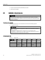
Intrinsically safe data
Table 2- 1
10
Sensor circuit
Sensor circuit
(Terminal 1-2)
Di3
Di6
Di15
Di25
Di40
Ui
16V
16V
16V
16V
16V
Ii
0.132A
0.132A
0.132A
0.132A
0.132A
Pi
0.75W
0.75W
0.75W
0.75W
0.75W
Li or Li/Ri
0.5mH or
80[μH/Ω]
1.5mH or
40[μH/Ω]
30[μH/Ω]
1mH or
10[μH/Ω]
15[μH/Ω]
Ci
50pF
50pF
50pF
50pF
50pF
SITRANS F C MASS 2100 Di 3-40
Operating Instructions, 07/2010, SFIDK.PS.028.Z1.02
Safety notes
2.2 Installation in hazardous area
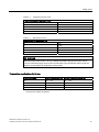
Table 2- 2
Temperature sensor circuit
Temperature sensor (Terminals 3,4 & 9)
Ui
15V
Ii
8mA
Pi
0.03W
Li
Insignificant
Ci
50pF
Table 2- 3
Pickup driver circuit
Pickup driver (Terminals 5-6 & 7-8)
Ui
15V
Ii
15mA
Pi
0.056W
Li
0.5mH
Ci
50pF
WARNING
With intrinsically safe circuits, use only certified transmitters appropriate for the sensor.
If a non-conforming supply unit is used, the "fail-safe" type of protection will no longer be
effective and the approval certification will be invalid.
Temperature specifications for Ex use
Temperature class
Ambient temperature [°C] Process media temperature [°C]
T3
-20 ... +50
-50 ... +180
T4
-20 ... +50
-50 ... +125
T5
-20 ... +50
-50 ... +90
T6
-20 ... +50
-50 ... +60
For ambient temperatures below -10°C and above +60°C use field wiring suitable for both minimum
and maximum ambient temperature.
SITRANS F C MASS 2100 Di 3-40
Operating Instructions, 07/2010, SFIDK.PS.028.Z1.02
11
Safety notes
2.2 Installation in hazardous area
Hazardous area safety requirements
It is required that:
● Electrical connections are in accordance with national directives such as IEC/EN6007914 (Installing Electrical Systems in Explosion Hazardous Areas).
● Sensor and transmitter are connected to the potential equalization.
WARNING
Laying of cables
Cable for use in zone 1 and 2 or 21 and 22 must satisfy the requirements for having a
proof voltage AC 500 V applied between the conductor/ground, conductor/shield and
shield/ground.
12
SITRANS F C MASS 2100 Di 3-40
Operating Instructions, 07/2010, SFIDK.PS.028.Z1.02
3
Description
Measurement of liquids and gases
SITRANS F C Coriolis mass flow meters are designed for measurement of a variety of
liquids and gases. The meters are multi parameter devices offering accurate measurement
of mass flow, volume flow, density, fraction, Brix/Plato, and temperature.
Main applications
The main applications of the Coriolis flow meter can be found in all industries, such as:
● Chemical & Pharma: Detergents, bulk chemicals, pharmaceuticals, acids, alkalis
● Food & Beverage: Dairy products, beer, wine, softdrinks, plato/brix, fruit juices and pulps,
bottling, CO2 dosing, CIP/SIP-liquids
● Automotive: Fuel injection, nozzle & pump testing, filling of AC units, engine consumption,
paint robots
● Oil & Gas: Filling of gas bottles, furnace control, CNG-dispensers, test separators
● Water & Waste Water: Dosing of chemicals for water treatment
3.1
Design
Versions
MASS 2100 DI 3-40, remote
version
MASS 2100 compact mounted MASS 2100 compact mounted
with MASS 6000 IP67
with MASS 6000 Ex d
The MASS 2100 Di3–40 is designed for use with the whole range of SITRANS F C
transmitters presently including MASS 6000 IP67, MASS 6000 19", MASS 6000 Ex d and
Siflow FC070.
All transmitters are suitable for remote installation and the MASS 6000 IP67 and MASS 6000
Ex d transmitters are also applicable for compact installations (mounted directly on the
sensor). Regardless of transmitter version, the accuracy specification remains valid.
SITRANS F C MASS 2100 Di 3-40
Operating Instructions, 07/2010, SFIDK.PS.028.Z1.02
13
Description
3.1 Design
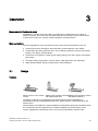
Description
①
②
③
④
⑤
⑥
⑦
Transmitter connection
Threaded hole for e.g. pressure guard
Nipple
Process connector
Mounting bracket
Type plate
Earth terminal
Figure 3-1
Product description
Design
The MASS 2100 sensor design is based on a single bent tube welded directly to the process
connections at each end. The tube has a large internal diameter which reduces pressure
loss and improves overall flow capacity. All Mass 2100 sensors come with an intrinsically
safe Ex design.
The sensors are available in two material configurations (W1.4435, AISI 316L or W2.4602,
Hastelloy C22). The enclosure is made of stainless steel W1.4301, AISI 316L with an
encapsulation grade of IP67/NEMA 4.
Maximum immunity towards process noise is among many things obtained through the
center block.
The sensors can be equipped with a pressure guard or flushed at the corresponding holes at
the end of the sensor.
14
SITRANS F C MASS 2100 Di 3-40
Operating Instructions, 07/2010, SFIDK.PS.028.Z1.02
Description
3.2 Theory of operation
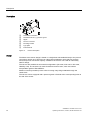
Heating Jacket
MASS 2100, DI 3 to DI 40 can optionally be ordered with an integral heating coil to avoid
solidification of sensitive fluids as e.g. chocolate or bitumen during down-time or periods
between discontinuing processes. This feature gives the freedom to let e.g. hot water,
superheated steam or hot oil maintain a constant temperature inside the sensor.
Figure 3-2
①
②
integral heating connector
Process connector
Figure 3-3
3.2
MASS 2100 heating jacket version cut-off
MASS 2100 heating jacket version
Theory of operation
The flow measuring principle is based on Coriolis law of movement.
The Sitrans F C sensors are energized by an electromechanical driver circuit which
oscillates the pipe at its resonant frequency. Two pick-ups, 1 and 2 are placed symmetrically
on both sides of the driver. When the media flows through the sensor, Coriolis force will act
on the measuring tube and cause a tube deflection which can be measured as a phase shift
between pick-up 1 and pick up 2.
The phase shift is proportional to the mass flow rate. The amplitude of the driver is
automatically regulated via a "phase locked loop", to ensure a stable output from the 2
pickups in the region of 80 to 120 mV. The temperature of the sensor is measured by a
Pt1000, in a 4-wire configuration.
The flow proportional signal from the 2 pick-ups, the temperature measurement and the
driver frequency are fed into the transmitter for calculations of mass, density, volume,
fraction, Brix/Plato, and temperature.
SITRANS F C MASS 2100 Di 3-40
Operating Instructions, 07/2010, SFIDK.PS.028.Z1.02
15
Description
3.2 Theory of operation
SENSORPROM
All SITRANS F C Coriolis flow meters feature a SENSORPROM® memory unit which stores
sensor specific calibration data and transmitter settings for the lifetime of the product. The
factory settings matching the sensor are stored in the SENSORPROM® unit. At
commissioning the flow meter commences measurement without any initial programming.
Also customer specified settings are downloaded to the SENSORPROM® unit.
Figure 3-4
16
Sensorprom memory unit
SITRANS F C MASS 2100 Di 3-40
Operating Instructions, 07/2010, SFIDK.PS.028.Z1.02
Installing/Mounting
4
SITRANS F flowmeters are suitable for in- and outdoor installations.
● Make sure that pressure and temperature specifications indicated on the device type
plate / label will not be exceeded.
WARNING
Installation in hazardous location
Special requirements apply to the location and interconnection of sensor and
transmitter. See "Installation in hazardous area" (Page 10)
4.1
Installation safety precautions
WARNING
In applications with working pressures/media that can be dangerous to people,
surroundings, equipment or others in case of pipe fracture, we recommend that special
precautions such as special placement, shielding or installation of a security guard or a
security valve are taken when the sensor is mounted.
● Ensure that stresses and loading caused by e.g. earthquakes, traffic, high winds and fire
damage if appropriate are taken into account during installation.
● Ensure that the flowmeter is installed such that it does not act as a focus for pipeline
stresses. External loadings are not taken into account in the flowmeter design.
● Provide adequate protection to minimise any risk of contact with hot surfaces.
WARNING
Prevent personal injuries by assuring that operation below pressure guards cannot take
place.
WARNING
The sensor enclosure is not rated for pressure containment.
SITRANS F C MASS 2100 Di 3-40
Operating Instructions, 07/2010, SFIDK.PS.028.Z1.02
17
Installing/Mounting
4.2 Determining a location
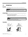
4.2
Determining a location
CAUTION
Do not install the sensor in the vicinity of strong electromagnetic fields, e.g. near motors,
pumps, transformers etc.
Upstream / downstream
● No pipe run requirements, i.e. straight inlet/outlet sections are not necessary.
● Avoid long drop lines downstream from the flow meter to prevent the meter tube from
draining (min. back pressure: 0.2 Bar).
● Avoid installing the sensor immediately upstream of a free discharge in a drop line.
Location in the system
The optimum location in the system depends on the application:
● Liquid applications
For liquid applications the presence of gas or air bubbles in the fluid may result in
erroneous measurements, particularly in the density measurement. Therefore do not
install the flow meter at the highest point in the system, where gas / air bubbles will be
trapped. For liquids it is advantageous to install the flow meter in low pipeline sections, at
the bottom of a U-section in the pipeline.
Figure 4-1
Liquid applications
● Gas applications
For gas applications the presence of oil may result in erroneous measurements.
Therefore do not install the flow meter at the lowest point of the system, or install a filter.
Figure 4-2
18
Gas applications
SITRANS F C MASS 2100 Di 3-40
Operating Instructions, 07/2010, SFIDK.PS.028.Z1.02
Installing/Mounting
4.3 Orienting the sensor
4.3
Orienting the sensor
Flow direction
The flow direction is indicated by the arrow on the sensor. Flow in this direction will be
indicated as positive.
CAUTION
The sensor must always be completely filled with process fluid in order to measure
accurately.
Orienting the sensor
MASS 2100 Di 3-40 operates in any orientation, but Siemens Flow Instruments recommends
orienting the sensor according to application type:
1. Horizontal installation (optimum orientation)
Especially suited for low flow applications: Solid particles will not be deposited in the tube
and the sensor can easily be degassed.
NOTICE
Self drainage
The flowmeter is self-draining if installed horizontally
2. Vertical installation with an upwards flow (only liquid applications).
Liquid applications
Horizontal installation, correct
Horizontal installation, wrong
Vertical installation, correct
Vertical installation, wrong
SITRANS F C MASS 2100 Di 3-40
Operating Instructions, 07/2010, SFIDK.PS.028.Z1.02
19
Installing/Mounting
4.3 Orienting the sensor
Gas applications
Horizontal installation
Vertical installation (not recommended)
Installation in a drop line
Installation in a dropline is only possible if a pipeline reduction or orifice with a smaller crosssection can be installed to prevent the sensor from being partially drained during the
measurements.
①
Orifice Pipe
②
Valve
Figure 4-3
20
Installation in drop line
SITRANS F C MASS 2100 Di 3-40
Operating Instructions, 07/2010, SFIDK.PS.028.Z1.02
Installing/Mounting
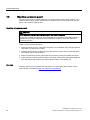
4.4 Mounting the sensor
4.4
Mounting the sensor
● Install the sensor in rigid pipelines in order to support the weight of the meter.
● Center the connecting pipelines axially in order to assure a stress-free installation.
● Install two supports or hangers symmetrically and stress free in close proximity to the
process connections.
Siemens Flow Instruments recommends installing the supports / hangers between sensor
enclosure and process connections.
Avoid vibrations
Use flexible hoses, if vibrations exist in the pipeline. The hoses must be installed outside the
supported flow meter section and outside the section between the shut off devices. The
direct connection of flexible elements to the sensor should be avoided.
Avoid crosstalk
Mount the sensors on separate steel frames, keep distance between the sensors, or
decouple the pipelines, if operating more than one meter in one or multiple interconnected
pipelines. This will prevent cross talk.
SITRANS F C MASS 2100 Di 3-40
Operating Instructions, 07/2010, SFIDK.PS.028.Z1.02
21
Installing/Mounting
4.5 Mounting a pressure guard
4.5
Mounting a pressure guard
The sensor enclosure is supplied with two 1/8" nipples. These holes can be used for e.g. a
pressure guard, which can be connected to an automatic shut off valve which will stop the
flow in case of sensor pipe fracture.
Mounting of pressure guard
CAUTION
Avoid moisture, liquids or particles getting into the sensor enclosure
All sensors are filled with argon to avoid condensation. Penetration of humidity, liquids or
particles into the sensor may influence the measurement and in worst case affect the
measuring function.
Install a pressure guard as follows:
1. Place the sensor in a dry, clean place and leave it to acclimatize until it reaches ambient
temperature, preferred 20°C (68°F).
2. Carefully disconnect the nipple and mount the pressure guard. Use the enclosed spare
part sealing ring for proper sealing.
3. Make sure that the pressure guard does NOT touch any of the parts inside the sensor.
4. Check that the pressure guard has been correctively mounted and thoroughly tightened.
After dismantling the sealing ring must be replaced with a new sealing ring.
See also
Pressure guards are not supplied with the sensor. For more information, please refer to
www.siemens.com/sitransp (http://www.siemens.com/sitransp)
22
SITRANS F C MASS 2100 Di 3-40
Operating Instructions, 07/2010, SFIDK.PS.028.Z1.02
5
Connecting
The following contains a short description of how to connect a remote mounted sensor to the
transmitter SITRANS F C MASS 6000 / SIFLOW FC070. For more information, including
information about compact versions, refer to the Operating Instructions for the respective
transmitters.
WARNING
Only qualified personnel may carry out work on the electrical connections.
Before connecting
● Check that serial numbers on sensor and SENSORPROM® unit are identical.
WARNING
Use in hazardous locations
Before connecting check that:
• No explosion hazard exists
• A fire department permission certificate has been issued
• All connection leads are potential free
Special requirements apply to the location and interconnection of sensor and
transmitter. See "Installation in hazardous area" (Page 10)
5.1
Safety precautions
WARNING
Mains supply from building installation Class II
A switch or circuit breaker (Max. 15 A) must be installed in close proximity to the equipment
and within easy reach of the operator. It must be marked as the disconnecting device for
the equipment.
WARNING
Field wiring installation
Ensure that the National Installation Code of the country in which the devices are installed
is met.
SITRANS F C MASS 2100 Di 3-40
Operating Instructions, 07/2010, SFIDK.PS.028.Z1.02
23
Connecting
5.2 Wiring
5.2
Wiring
1. Connect transmitter and sensor using the screw connector on the blue cable supplied
with the sensor.
Figure 5-1
Sensor and transmitter connection
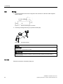
2. Connect grounding terminal ① to protective earth (PE).
Figure 5-2
Grounding terminal
NOTICE
Cable screen
Cable screen is connected to earth.
WARNING
Only commission the device after the device has been properly connected and, if
required, closed.
See also
Electrical connection schematics (Page 41)
24
SITRANS F C MASS 2100 Di 3-40
Operating Instructions, 07/2010, SFIDK.PS.028.Z1.02
Connecting
5.3 Turning the terminal box
5.3
Turning the terminal box
For remote versions, the adapter can optionally be oriented in four directions.
1. Loosen the four screws by use of an allen key and turn the adaptor.
2. Tighten the screws and mount the multiple plug.
SITRANS F C MASS 2100 Di 3-40
Operating Instructions, 07/2010, SFIDK.PS.028.Z1.02
25
Connecting
5.3 Turning the terminal box
26
SITRANS F C MASS 2100 Di 3-40
Operating Instructions, 07/2010, SFIDK.PS.028.Z1.02
Commissioning
6
Before commissioning it must be checked that:
● The device has been installed and connected in accordance with the guidelines provided
in chapter 4 "Installing / Mounting (Page 17)" and 5 "Connecting (Page 23)"
● Device installed in hazardous location meets the requirements described in "Installation in
hazardous location (Page 10)"
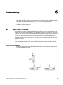
6.1
Zero point adjustment
Performing a zero point adjustment establishes the reference point of the flowmeter at zero
flow. All Coriolis sensors from Siemens are calibrated before they are sent out to customers.
However, Coriolis sensors are very sensitive, and several factors might move the zero point,
e.g. installation, pressure, temperature and even very small vibrations coming from the
process. All these factors are customer specific and cannot be simulated at the factory.
Therefore Siemens recommends carrying out a zero point adjustment before use to obtain
optimum accuracy.
In the following it is described how to zero point adjust the device. For setting application
specific parameters, please refer to the Operating Instructions of the relevant transmitter.
Before zero point adjusting
● Install shut off devices in the pipeline, optimally both up- and downstream of the sensor,
otherwise at the sensor outlet
Vertical
Horizontal
SITRANS F C MASS 2100 Di 3-40
Operating Instructions, 07/2010, SFIDK.PS.028.Z1.02
27
Commissioning
6.1 Zero point adjustment
CAUTION
In order to avoid damaging the pump and interrupting the process it is recommended to
install a bypass line
Auto zero point adjustment
● Power up the device and acclimate the transmitter (min. 30 min).
● Pump liquid at max. flow through the sensor (min. 2 min or until the driver signal and
driver frequency are stable) in order to avoid air in the liquid.
● Stop the flow while pumping by shutting off the outlet valve and then the inlet valve. Wait
min. 1 minute. In this way the liquid remain pressurized and any degassing is avoided.
Note
The flow must be completely stopped and the sensor completely filled with liquid.
● Perform an auto zero point adjustment:
MASS 6000
SIFLOW FC070
Choose menu entry "Reset mode"
Choose the SIMATIC PDM menu
-> Zero adjust
-> Device
-> Zero adjust auto
-> zero adjust
For further information on performing an auto zero point adjustment please refer to the
relevant transmitter Operating Instructions.
● After count down (30 s.), the actual zero point is displayed and the meter ready for
operation.
28
SITRANS F C MASS 2100 Di 3-40
Operating Instructions, 07/2010, SFIDK.PS.028.Z1.02
Service and maintenance
7.1
7
Maintenance
The device is maintenance-free, however, a periodic inspection according pertinent
directives and regulations must be carried out.
An inspection can include check of:
● Ambient conditions
● Seal integrity of the process connections, cable entries, and cover screws
● Reliability of power supply, lightning protection, and grounds
7.2
Transportation/storage
The sensor is a fragile piece of equipment. Impact and shock can
cause measuring inaccuracy. Therefore during transportation it must
be placed in the transportation box delivered by Siemens Flow
Instruments. If this is not possible, the alternative sensor packaging
must be able to withstand the hazards from transportation.
7.3
Recalibration
Siemens Flow Instruments offers to recalibrate the sensor. The following calibrations are
offered as standard according to configuration (standard, density, brix/plato, fraction):
● Standard calibration
● Customer specified calibration (up to 10 points)
● Accredited calibration
● Matched pair calibration
Note
For recalibration the SENSORPROM memory unit must always be returned with the
sensor
See also
Return procedures (Page 31)
SITRANS F C MASS 2100 Di 3-40
Operating Instructions, 07/2010, SFIDK.PS.028.Z1.02
29
Service and maintenance
7.4 Unit repair
7.4
Unit repair
CAUTION
Repair and service must be carried out by Siemens authorized personnel only.
Note
Siemens Flow Instruments defines sensors as non-repairable products.
7.5
Technical support
If you have any technical questions about the device described in these Operating
Instructions and do not find the right answers, you can contact Technical Support:
● Via the Internet using the Support Request:
Support request (http://www.siemens.com/automation/support-request)
● Phone: +49 (0)911 895 7222
Further information about our technical support is available in the Internet at
Technical support (http://support.automation.siemens.com/WW/view/en/16604318)
Service & Support on the Internet
In addition to our documentation, we offer a comprehensive knowledge base online on the
Internet at:
Service and support (http://www.siemens.com/automation/service&support)
There you will find:
● The latest product information, FAQs, downloads, tips and tricks.
● Our newsletter, providing you with the latest information about your products.
● A Knowledge Manager to find the right documents for you.
● Our bulletin board, where users and specialists share their knowledge worldwide.
● You can find your local contact partner for Industry Automation and Drives Technologies
in our partner database.
● Information about field service, repairs, spare parts and lots more under "Services."
Additional Support
Please contact your local Siemens representative and offices if you have additional
questions about the device
Find your contact partner at:
Local contact person (http://www.automation.siemens.com/partner)
30
SITRANS F C MASS 2100 Di 3-40
Operating Instructions, 07/2010, SFIDK.PS.028.Z1.02
Service and maintenance
7.6 Return procedures
7.6
Return procedures
Enclose the delivery note, the cover note for return delivery together with the declaration of
decontamination form on the outside of the package in a well-fastened clear document
pouch.
Required forms
● Delivery Note
● Cover Note for Return Delivery with the following information
Decontamination declaration
(http://pia.khe.siemens.com/efiles/feldg/files/Service/declaration_of_decontamination_en.
pdf)
– product (ordering number)
– number of devices or spare parts returned
– reason for the return
● Declaration of Decontamination
Return delivery form (http://support.automation.siemens.com/WW/view/en/16604370)
With this declaration you certify that the returned products/spare parts have been
carefully cleaned and are free from any residues.
If the device has been operated together with toxic, caustic, flammable or waterdamaging products, clean the device before return by rinsing or neutralizing. Ensure that
all cavities are free from dangerous substances. Then, double-check the device to ensure
the cleaning is completed.
We shall not service a device or spare part unless the declaration of decontamination
confirms proper decontamination of the device or spare part. Shipments without a
declaration of decontamination shall be cleaned professionally at your expense before
further proceeding.
You can find the forms on the Internet and on the CD delivered with the device.
SITRANS F C MASS 2100 Di 3-40
Operating Instructions, 07/2010, SFIDK.PS.028.Z1.02
31
Service and maintenance
7.6 Return procedures
32
SITRANS F C MASS 2100 Di 3-40
Operating Instructions, 07/2010, SFIDK.PS.028.Z1.02
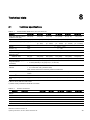
8
Technical data
8.1
Technical specifications
Table 8- 1
Technical data, MASS 2100, Di 3,6,15,25 and 40.
Versions
mm (inch)
DI 3 (1/8)
DI 6 (¼)
DI 15 (5/8)
DI 25 (1)
Inside pipe diamter (sensor
consists of one pipe)
mm (inch)
3.0 (0.12)
6.0 (0.24)
14.0 (0.55)
29.7 (1.17)
Pipe wall thickness
mm (inch)
0.5 (0.02)
1.0 (0.04)
1.0 (0.04)
2,0 (0.08)
2,6 (0.10)
0 ... 250
0 ... 1000
0 ... 5600
0 ... 25000
0 ... 52000
(0 ... 500)
(0 ... 2200)
(0 ... 12345)
(0 ... 55100)
(0 ... 114600)
Massflow measuring range
kg/h
(lb/inch3)
Density
g/cm3
0 ... 2.9 (0 ... 0.10)
Fraction, e.g.
°Brix
0 ... 100
Temperature
°C (°F)
DI 40 (1½)
43,1(1.70)
-50 ... +180 (-58 ... +356)
Pressure of liquid in
measuring pipe1)
Stainless steel
bar (psi)
230 (3336)
265 (3844)
130 (1885)
110 (1595)
105 (1523)
Hastelloy C-22
bar (psi)
350 (5076)
410 (5946)
200 (2900)
185 (2683)
-
Materials (Measuring pipe,
flange and thread
connection)
•
•
1.4435/1.4404 (AISI 316L) (stainless steel)
2.4602 (Hastelloy C-22) (only Di 3, 6 ,15 and 25)
Enclosure and enclosure
material
•
•
IP 65 (NEMA 4)
W 1.4404 AISI 316L) (stainless steel)
Note: Sensor enclosure not rated for pressure containment
Cable connection
Multiple connector to sensors 5 x 2 x 0.35 mm2, twisted and shielded pairs, external diameter
12 mm
EX-version2)
EEx ia IIC T3-T6
Weight, approx. (Sensor
only)
kg (lb)
4 (8.8)
8 (17.6)
12 (26.5)
48 (105.8)
70 (154.5)
1) Max. at 20°C, DIN 2413, DIN 17457
2) Intrinsic safety certification CENELEC and ASEV
Table 8- 2
Process connections
Versions
mm (inch)
DI 3 (1/8)
DI 6 (¼)
DI 15 (5/8)
DI 25 (1)
DI 40 (1½)
Flange
EN 1092-1 PN40
DN 10
DN 10
DN 15
DN 25
DN 40
ANSI B16,5, Class 150
1/2"
1/2"
1/2"
1"
1 1/2"
1/2"
1/2"
1/2"
1"
1 1/2"
DN 10
DN 10
DN 15
DN 25
DN 40
ANSI B16,5 Class 600 (Class 300)
Dairy screwed connection (PN
16/25/40)1)
DIN 11851
SITRANS F C MASS 2100 Di 3-40
Operating Instructions, 07/2010, SFIDK.PS.028.Z1.02
33
Technical data
8.2 Measurement range
Versions
mm (inch)
DI 3 (1/8)
ISO 2853/BS 4825 Part 4 (SS3351)
DI 6 (¼)
DI 15 (5/8)
DI 25 (1)
DI 40 (1½)
25 mm
25 mm
25 mm
38 mm
51 mm
25 mm
25 mm
25 mm
38 mm
51 mm
ISO 228/1, PN 100
G1/4" female
G1/4" male
G1/2" male
G1" male
G2" male
ANSI/ASME B1.20.1, PN 100
1/4" NPT
female
1/4" NPT
male
1/2" NPT
male
1" NPT male
2" NPT
male
Dairy clamp connection (PN 16)1)
ISO 2852/BS 4825 Part 3 (SMS3016)
Thread
1) Material, 1.4401 or corresponding
8.2
Measurement range
Measuring accuracy of frequency and pulse outputs
(UURULQRI
DFWXDOPDVVIORZUDWHZLWKFRQILGHQFHSUREDELOLW\
$FWXDO
PDVVIORZUDWH
VHQVRUV
PD[IORZUDWH
Figure 8-1
Measuring accuracy
Table 8- 3
Measurement range
Sensor size
Max. flow of sensor at
5%
50 %
100 %
DI 3
kg/h
12.5
125
250
DI 6
kg/h
50
500
1000
DI 15
kg/h
280
2800
5600
DI 25
kg/h
1250
12500
25000
DI 40
kg/h
2600
26000
52000
● At a flow > 5 % of the max. measurement range, you can directly read the error on the
curve.
● At a flow < 5 % of the max. measurement range, use the equation to calculate the error.
The error curve is calculated using the formula:
34
SITRANS F C MASS 2100 Di 3-40
Operating Instructions, 07/2010, SFIDK.PS.028.Z1.02
Technical data
8.3 Accuracy specifications
E
error [%]
Z
zero point error [kg/h]
Qm
mass flow [kg/h]
Figure 8-2
Equation for error curve
Example Di3
● Max zero point error Z = 0.01 kg/h
● Measured mass flow Qm = 12 kg/h
● Error E = ±0.13%
8.3
Table 8- 4
Accuracy specifications
Measuring type errors
Sensor size
DI 3
DI 6
DI 15
DI 25
DI 40
1
Number of measuring tubes
Massflow
Linearity error
%
0.10
Repeatability error
%
0.05
Max. zero point error
kg/h
0.01
0.05
0.2
1.5
6.0
Density error
g/cm3
0.0015
0.0015
0.0005
0.0005
0.0005
Repeatability error
g/cm3
0.0002
0.0002
0.0001
0.0001
0.0001
Temperature error
°C
0.1
0.1
Density
Brix error
°Brix
0.5
0.3
0.3
0.1
Reference conditions (ISO 9104 and DIN / EN 29104)
Table 8- 5
Reference conditions
Flow conditions
Fully developed flow profile
Temperature of the medium
20 °C ± 2 K
Ambient temperature
20 °C ± 2 K
Liquid pressure
2 ± 1 bar
Density
0.997 g / cm3
Brix
40 ° Brix
Supply voltage
Un ± 1 %
Warming-up time
30 min
Cable length
5 m between transmitter and sensor
SITRANS F C MASS 2100 Di 3-40
Operating Instructions, 07/2010, SFIDK.PS.028.Z1.02
35
Technical data
8.4 Pressure drop
Additional error on deviation from reference conditions
Current output
As pulse output (± 0.1% of actual flow +0.05%
FSO)
Effect of ambient temperature
Display/Frequency/pulse output:
• < ±0.003 % / K measured value
Current output:
• < ± 0.005% / K act.
Effect of supply voltage
8.4
< 0.005% of measuring value on 1% alteration
Pressure drop
The pressure drop through the instrument is a function of the properties of the fluid viscosity
and the flow rate.
In the following charts, the pressure drop for the various sensor sizes is available (Reference
density is 1000 kg/m3). The charts are used for correct sensor dimensioning with regard to
capacity, pressure loss and accuracy.
Figure 8-3
36
MASS 2100 DI3
SITRANS F C MASS 2100 Di 3-40
Operating Instructions, 07/2010, SFIDK.PS.028.Z1.02
Technical data
8.4 Pressure drop
Figure 8-4
MASS 2100 DI6
Figure 8-5
MASS 2100 DI15
Figure 8-6
MASS 2100 DI25
SITRANS F C MASS 2100 Di 3-40
Operating Instructions, 07/2010, SFIDK.PS.028.Z1.02
37
Technical data
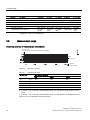
8.5 Pressure / temperature range
Figure 8-7
8.5
MASS 2100 DI40
Pressure / temperature range
The pressure - temperature ratings depend on type of process connection.
110
100
352&(6635(6685(EDU
90
31
82
80
70
60
31
52
50
40
33 31
30
-50
30
80
130
180
352&(667(03(5$785(r&
Figure 8-8
Flange EN1092.1 W1.4404 /4435
110
100
90
352&(6635(6685(EDU
31
80
79
70
60
31
50
50
40
31
30
-50
30
80
130
31
180
352&(667(03(5$785(r&
Figure 8-9
38
Flange EN1092.1, W2.4602
SITRANS F C MASS 2100 Di 3-40
Operating Instructions, 07/2010, SFIDK.PS.028.Z1.02
Technical data
8.5 Pressure / temperature range
90
80
352&(6635(6685(EDU
70
&/$66
60
60
50
40
&/$66
30
30
20
&/$66
12
10
-50
30
80
130
180
352&(667(03(5$785(r&
Figure 8-10
Flange ASME B16.5, W1.4404 / 4435
110
&/$66
100
98
90
352&(6635(6685(EDU
80
70
60
&/$66
50
49
40
30
20
15
10
-50
30
80
352&(667(03(5$785(r&
Figure 8-11
130
&/$66
180
Flange ASME B16.5, W2.4602
352&(6635(6685(EDU
260
210
31
188
164
160
110
92
71
60
-50
30
80
130
31
31
31
180
352&(667(03(5$785(r&
Figure 8-12
Flange ISO228, Pipe thread, W1.4404 / 4435
420
352&(6635(6685(EDU
370
31
320
322
270
31
287
275 31
220
170
31
157
145 31
120
-50
30
80
130
180
352&(667(03(5$785(r&
Figure 8-13
Flange ISO228, Pipe thread, W2.4602
SITRANS F C MASS 2100 Di 3-40
Operating Instructions, 07/2010, SFIDK.PS.028.Z1.02
39
Technical data
8.5 Pressure / temperature range
45
40
40
31'1
352&(6635(6685(EDU
35
30
25
25
31'1
20
31'1
15
10
-50
0
20
40
60
80
100
120
140
352&(667(03(5$785(r&
Figure 8-14
Flange DIN 11851, W1.4404
30
25
352&(6635(6685(EDU
25
31
20
16
15
10
10
31
31
5
-50
5
25
45
65
85
105
125
145
352&(667(03(5$785(r&
Figure 8-15
40
Flange DIN 32676, W1.4404
SITRANS F C MASS 2100 Di 3-40
Operating Instructions, 07/2010, SFIDK.PS.028.Z1.02
Technical data
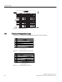
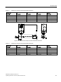
8.6 Electrical connection schematics
8.6
Electrical connection schematics
Electrical connection, MASS 2100 with MASS 6000 (remote mounted)
①
②
③
④
⑤
Driver
PT 1000 (IN)
PT 1000 (OUT)
Pick up 2
Pick up 1
Figure 8-16
MASS 2100 / MASS 6000 Connection
SITRANS F C MASS 2100 Di 3-40
Operating Instructions, 07/2010, SFIDK.PS.028.Z1.02
41
Technical data
8.7 Dimensions and weight
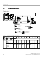
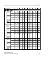
8.7
Dimensions and weight
Remote versions
)ODQJH(1
$16,%
'DLU\VFUHZHG
FRQQHFWLRQ
',1VFUHZHG
6FUHZHGFRQQHFWRUIRU
'L,62*~
DQG$16,$60(
%~137
Table 8- 6
Dimensions and weight, remote versions
Sensor Connection
size
DI
(Inch)
Type
(size)
L1
Pressure
rating
L2
L3
H1
B1
D1
D2
D3
D4
D5
75.5
60
0
21.3
104
-
-
-
-
-
-
mm (inch)
3 (1/8") Pipe
PN 100
thread ISO
228/1 G¼ (¼")
400
280
(15.75)
(11.02) (2.97)
(2.36)
(0)
(0.84)
(4.09)
Pipe
PN 100
thread
ANSI/ASM
E B 1.20.1
- ¼" NPT
(¼")
400
280
60
0
21.3
104
(15.75)
(11.02) (2.97)
(2.36)
(0)
(0.84)
(4.09)
42
75.5
SITRANS F C MASS 2100 Di 3-40
Operating Instructions, 07/2010, SFIDK.PS.028.Z1.02
Technical data
8.7 Dimensions and weight
Sensor Connection
size
L1
DI
(Inch)
Type
(size)
Pressure
rating
6 (¼")
Flange EN PN 100
1092-1
(DN 10)
PN 40
L3
H1
B1
D1
D2
D3
D4
D5
62.0
40
12
17.0
104
100
70.0
14.0
mm (inch)
580
390
(22.83)
(15.35) (2.44)
(1.57)
(0.47)
(0.67)
(4.09)
(3.94)
(2.76)
(0.55)
560
390
40
12
17.0
104
90.0
60.0
14.0
(22.05)
(15.35) (2.44)
(1.57)
(0.47)
(0.67)
(4.09)
(3.54)
(2.36)
(0.55)
390
40
12
17.0
104
88.9
60.5
15.7
(15.35) (2.44)
(1.57)
(0.47)
(0.67)
(4.09)
(3.5)
(2.38)
(0.62)
390
40
12
17.0
104
95.3
66.5
15.7
(3.75)
(2.62)
(0.62)
-
-
-
-
-
Flange
Class 150 624
ANSI
(24.57)
B16.5 (½")
Class 600 608
62.0
62.0
62.0
(23.94)
(15.35) (2.44)
(1.57)
(0.47)
(0.67)
(4.09)
Screwed
PN 40
connection
DIN 11851
(DN10)
532
390
40
12
17.0
104
(20.94)
(15.35) (2.44)
(1.57)
(0.47)
(0.67)
(4.09)
PN 16
570
390
40
12
17.0
104
(22.44)
(15.35) (2.44)
(1.57)
(0.47)
(0.67)
(4.09)
634
444
44
20
21.3
129
105
75.0
14.0
(24.96)
(17.48) (2.97)
(1.73)
(0.79)
(0.84)
(5.08)
(2.95)
(4.13)
(0.55)
620
444
44
20
21.3
129
95.0
65.0
14.0
(24.41)
(17.48) (2.97)
(1.73)
(0.79)
(0.84)
(5.08)
(3.74)
(2.56)
(0.55)
444
Clamp
ISO 2852
(25 mm)
15 (½") Flange EN PN 100
1092-1
(DN15)
PN 40
Flange
Class 150 639
ANSI
(25.16)
B16.5 (½")
Class 600 660
25(1")
L2
62.0
62.0
75.5
75.5
44
20
21.3
129
88.9
60.5
15.7
(17.48) (2.97)
75.5
(1.73)
(0.79)
(0.84)
(5.08)
(3.5)
(2.38)
(0.62)
444
44
20
21.3
129
95.3
66.5
15.7
(25.98)
(17.48) (2.97)
(1.73)
(0.79)
(0.84)
(5.08)
(3.75)
(2.62)
(0.62)
Screwed
PN 40
connection
DIN 11851
(DN15)
586
444
44
20
21.3
129
-
-
-
(23.07)
(17.48) (2.97)
(1.73)
(0.79)
(0.84)
(5.08)
Clamp
ISO 2852
(25 mm)
624
444
44
20
21.3
129
-
-
-
(24.57)
(17.48) (2.97)
(1.73)
(0.79)
(0.84)
(5.08)
970
700
126
25
33.7
219
140.0
100.0
18.0
(38.19)
(27.56) (2.97)
(4.96)
(0.98)
(1.33)
(8.62)
(3.94)
(5.51)
(0.71)
934
700
126
25
33.7
219
115.0
85.0
14.0
(36.77)
(27.56) (2.97)
(4.96)
(0.98)
(1.33)
(8.62)
(4.53)
(3.35)
(0.55)
700
126
25
33.7
219
108.0
79.2
15.7
(27.56) (2.97)
(4.96)
(0.98)
(1.33)
(8.62)
(4.25)
(3.12)
(0.62)
700
126
25
33.7
219
124.0
88.9
19.1
PN 16
Flange EN PN 100
1092-1
(DN25)
PN 40
Flange
ANSI
B16.5 (1")
Class 150 967
(38.07)
Class 600 992
Screwed
PN 40
connection
DIN 11851
(DN32)
75.5
75.5
75.5
75.5
75.5
75.5
75.5
(39.06)
(27.56) (2.97)
(4.96)
(0.98)
(1.33)
(8.62)
(4.88)
(3.50)
(0.75)
922
700
126
25
33.7
219
-
-
-
(36.30)
(27.56) (2.97)
(4.96)
(0.98)
(1.33)
(8.62)
SITRANS F C MASS 2100 Di 3-40
Operating Instructions, 07/2010, SFIDK.PS.028.Z1.02
75.5
43
Technical data
8.7 Dimensions and weight
Sensor Connection
size
DI
(Inch)
40
(1½")
L1
L2
L3
H1
B1
D1
D2
D3
D4
D5
74.5
126
25
33.7
219
-
-
-
Type
(size)
Pressure
rating
mm (inch)
Clamp
ISO 2852
(38 mm)
PN 16
940
700
(37.01)
(27.56) (2.93)
(4.96)
(0.98)
(1.33)
(8.62)
1100
850
180
0
48.3
273
170.0
125.0
22.0
Flange EN PN 100
1092-1
PN 40
Flange
ANSI
B16.5
(1½")
71.5
(43.31)
(33.46) (2.81)
(7.09)
(0)
(1.9)
(10.75) (4.92)
(6.69)
(0.87)
1063
850
180
0
48.3
850
150.0
110.0
18.0
(41.85)
(33.46) (2.81)
(7.09)
(0)
(1.9)
(10.75) (5.91)
(4.33)
(0.71)
850
180
0
48.3
850
98.6
15.7
(33.46) (2.81)
(7.09)
(0)
(1.9)
(10.75) (5.91)
(4.33)
(0.71)
850
Class 150 1100
(43.31)
Class 600 1128
71.5
71.5
180
0
48.3
850
155.4
114.3
22.4
(44.41)
(33.46) (2.81)
(7.09)
(0)
(1.9)
(10.75) (6.12)
(4.50)
(0.88)
Screwed
PN 25
connection
DIN 11851
(DN 50)
1090
850
180
0
48.3
850
-
-
-
(42.91)
(33.46) (2.81)
(7.09)
(0)
(1.9)
10.75
()
Clamp
ISO 2852
(51 mm)
1062
850
180
0
48.3
850
-
-
-
(41.81)
(33.46) (2.81)
(7.09)
(0)
(1.9)
(10.75)
PN 25
71.5
127.0
71.5
71.5
Compact versions
Figure 8-17
44
MASS 2100 compact mounted with MASS 6000 Ex d
SITRANS F C MASS 2100 Di 3-40
Operating Instructions, 07/2010, SFIDK.PS.028.Z1.02
Technical data
8.7 Dimensions and weight
Table 8- 7
Sensor size
[DI (inch)]
MASS 2100 compact mounted with MASS 6000 Ex d
L3
mm (inch)
H5
mm (inch)
H6
mm (inch)
H5+H6
mm (inch)
3 (1/8)
75 (2.95)
82 (3.23)
247 (9.72)
329 (12.95)
6 (¼)
62 (2.44)
72 (2.83)
257 (10.12)
329 (12.95)
15 (½)
75 (2.95)
87 (3.43)
267 (10.51)
354 (13.94)
25 (1)
75 (2.95)
173 (6.81)
271 (10.67)
444 (17.48)
40 (1½)
75 (2.95)
227 (8.94)
271 (10.67)
498 (19.61)
Figure 8-18
Table 8- 8
MASS 2100 compact mounted with MASS 6000 IP67
MASS 2100 compact mounted with MASS 6000 IP67
Sensor size
[DI (inch)]
L3
mm (inch)
H5
mm (inch)
H6
mm (inch)
H5+H6
mm (inch)
3 (1/8)
75 (2.95)
82 (3.23)
306 (12.04)
388 (15.28)
6 (¼)
62 (2.44)
72 (2.83)
316 (12.44)
388 (15.28)
15 (½)
75 (2.95)
87 (3.43)
326 (12.83)
413 (16.26)
25 (1)
75 (2.95)
173 (6.81)
330 (13.00)
503 (19.80)
40 (1½)
75 (2.95)
227 (8.94)
330 (13.00)
557 (21.93)
SITRANS F C MASS 2100 Di 3-40
Operating Instructions, 07/2010, SFIDK.PS.028.Z1.02
45
Technical data
8.7 Dimensions and weight
Heating Jacket versions
Figure 8-19
Table 8- 9
Dimensions, MASS 2100 with heating jacket
Dimensions, MASS 2100 with heating jacket
Sensor
size
Connections
DI (inch)
Type (Size)
Pressure
rating
mm (inch)
DI 3
(1/8")
EN 1092-1
(DN 15)
PN 40
ANSI B16.5
(½")
DI 6 (¼")
DI 15
(½")
H3
B2
D6
D7
D8
234 (9.21)
122 (4.8)
22 (0.87)
95 (3.74)
65.0 (2.56)
14.0 (0.55)
Class 150
234 (9.21)
131.6
(5.18)
22 (0.87)
88.9 (3.5)
60.5 (2.38)
15.7 (0.62)
EN 1092-1
(DN 15)
PN 40
234 (9.21)
112 (4.41)
22.7 (0.89)
95 (3.74)
65.0 (2.56)
14.0 (0.55)
ANSI B16.5
(½")
Class 150
234 (9.21)
121.6
(4.79)
22.7 (0.89)
88.9 (3.5)
60.5 (2.38)
15.7 (0.62)
EN 1092-1
(DN 15)
PN 40
234 (9.21)
126.5
(4.98)
31.5 (1.24)
95 (3.74)
65.0 (2.56)
14.0 (0.55)
ANSI B16.5
(½")
Class 150
234 (9.21)
136.1
(5.36)
31.5 (1.24)
88.9 (3.5)
60.5 (2.38)
15.7 (0.62)
PN 40
420 (16.54) 213.6
(8.41)
60 (2.36)
95 (3.74)
65.0 (2.56)
14.0 (0.55)
ANSI B16.5
(½")
Class 150
420 (16.54) 223.2
(8.79)
60 (2.36)
88.9 (3.5)
60.5 (2.38)
15.7 (0.62)
EN 1092-1
(DN 15)
PN 40
500 (19.68) 267.5
(10.53)
43 (1.69)
95 (3.74)
65.0 (2.56)
14.0 (0.55)
ANSI B16.5
(½")
Class 150
500 (19.68) 277.1
(10.91)
43 (1.69)
88.9 (3.5)
60.5 (2.38)
15.7 (0.62)
DI 25 (1") EN 1092-1
(DN 15)
DI 40
(1½")
46
L5
SITRANS F C MASS 2100 Di 3-40
Operating Instructions, 07/2010, SFIDK.PS.028.Z1.02
A
Appendix
Certificates are posted on the Internet and on the manual collection shipped with the device.
See also
Certificates on the Internet
(http://support.automation.siemens.com/WW/view/en/10806951/134200)
UL control drawings on the internet (http://www.automation.siemens.com/w1/automationtechnology-process-instrumentation-18092.htm#lb-61,related-installationdrawings)
A.1
Ordering
In order to ensure that the ordering data you are using is not outdated, the latest ordering
data is always available on the Internet: Process instrumentation catalog
(http://www.siemens.com/processinstrumentation/catalogs)
SITRANS F C MASS 2100 Di 3-40
Operating Instructions, 07/2010, SFIDK.PS.028.Z1.02
47
Appendix
A.1 Ordering
48
SITRANS F C MASS 2100 Di 3-40
Operating Instructions, 07/2010, SFIDK.PS.028.Z1.02
Glossary
ASIC
Application-Specific Integrated Circuit is an integrated circuit (IC) customized for a particular
use, rather than intended for general-purpose use.
BRIX
Degrees Brix (symbol °Bx) is a measurement of the mass ratio of dissolved sugar to water in
a liquid. A 25 °Bx solution is 25% (w/w), with 25 grams of sugar per 100 grams of solution.
CAN
Controller Area Network. CAN is the leading serial bus system for embedded control. CAN is
a mainstream network and was internationally standardized (ISO 11898–1) in 1993.
Coriolis
The Coriolis effect is an apparent deflection of moving objects from a straight path when they
are viewed from a rotating frame of reference. The effect is named after Gaspard-Gustave
Coriolis, a French scientist who described it in 1835. The Coriolis effect is caused by the
Coriolis force, which appears in the equation of motion of an object in a rotating frame of
reference.
DFT
The discrete Fourier transform (DFT) is one of the specific forms of Fourier analysis. As
such, it transforms one function into another, which is called the frequency domain
representation, or simply the DFT, of the original function (which is often a function in the
time domain). The DFT evaluates enough frequency components to reconstruct the finite
segment that was analyzed. The DFT is thus a transform for Fourier analysis of finite-domain
discrete-time functions.
EMC
Electromagnetic compatibility (EMC) is the branch of electrical sciences which studies the
unintentional generation, propagation and reception of electromagnetic energy with
reference to the unwanted effects (Electromagnetic Interference, or EMI) that such energy
may induce. The goal of EMC is the correct operation, in the same electromagnetic
environment, of different equipment which use electromagnetic phenomena, and the
avoidance of any interference effects.
SITRANS F C MASS 2100 Di 3-40
Operating Instructions, 07/2010, SFIDK.PS.028.Z1.02
49
Glossary
Fraction
Fraction designates a proportional relation between an object part and the object whole. For
example, the fraction 3⁄4 represents three equal parts of a whole object, divided into four
equal parts.
HART
HART Communication is a bi-directional industrial field communication protocol used to
communicate between intelligent field instruments and host systems. HART is the global
standard for smart process instrumentation and the majority of smart field devices installed in
plants worldwide are HART-enabled. HART technology is easy to use and very reliable
IP
An IP (Ingress Protection) number is used to specify the environmental protection of
enclosures around electronic equipment. These ratings are determined by specific tests. The
IP number is composed of two numbers, the first referring to the protection against solid
objects and the second against liquids. The higher the number, the better the protection. For
example, in IP67 the first Number (6) means that the device is totally protected against dust,
and the second (7) that it is protected against the effect of immersion between 15cm and 1m
MODBUS
MODBUS is a serial communications protocol intended for use with programmable logic
controllers (PLCs). MODBUS allows for communication between many devices connected to
the same network, for example a system that measures temperature and humidity and
communicates the results to a computer. MODBUS is often used to connect a supervisory
computer with a remote terminal unit (RTU) in supervisory control and data acquisition
systems.
NAMUR
Normenarbeitsgemeinschaft für Meß- und Regeltechnik in der Chemischen Industrie
(NAMUR). NAMUR is a group representing the interests of the chemical industry which
create standards for instrumentation and electrical devices used in industrial plants.
PED
The Pressure Equipment Directive (97/23/EC) is the legislative framework on European level
for equipment subject to a pressure hazard. It was adopted by the European Parliament and
the European Council in May 1997 and has been obligatory throughout the European Union
since May 2002.
Plato
Plato is a measure of the weight of the solids dissolved in water. It is expressed in %.
50
SITRANS F C MASS 2100 Di 3-40
Operating Instructions, 07/2010, SFIDK.PS.028.Z1.02
Glossary
PROFIBUS
PROFIBUS (Process Field Bus) is a vendor-independent, open bus system standardized in
the German DIN 19 245. It is a standard for field bus communication in automation
technology and should not be confused with the PROFINET standard for industrial Ethernet.
PROFIBUS-PA (Process Automation) is one of three PROFIBUS variants that are
compatible with each other. PROFIBUS-DP (Decentralized Periphery)
SENSORPROM
All sensor related settings/data saved on an EPROM. SENSORPROM technology
automatically configures the transmitter at start up providing calibration data, pipe size,
sensor type, and output settings. The SENSORPROM automatically stores values or
settings changed by users, and automatically re-programs any new transmitter without loss
of accuracy.
Turndown ratio
'Turndown ratio' is a flow measurement term indicating the range a specific flow meter, or
meter type, is able to measure with specific accuracy. It is also known as rangeability. If a
gas flow to be measured is expected to vary between 100,000 m³ per day and 1,000,000 m³
per day, the specific application has a turndown ratio of at 10:1. Therefore the meter requires
a turndown ratio of at least 10:1.
USM
USM II is a Communication Platform. The Siemens USM II concept enables fitting of add-on
bus modules without loss of functionality:
1. All modules can be fitted as true "plug & play"
2. Module and transmitter are automatically configured through the SENSORPROM
Zero point adjustment
In order to measure accurately with a measuring instrument it is important that zero and gain
have been calibrated. All Coriolis sensors are calibrated before they are sent out to
customers. However, Coriolis sensors are very sensitive, and several factors might move the
zero point, e.g installation, pressure, temperature and even very small vibrations coming
from the process. All these factors are customer specific and can’t be simulated at the
factory. Therefore Siemens recommends to carry out a zero point adjustment before use.
SITRANS F C MASS 2100 Di 3-40
Operating Instructions, 07/2010, SFIDK.PS.028.Z1.02
51
Glossary
52
SITRANS F C MASS 2100 Di 3-40
Operating Instructions, 07/2010, SFIDK.PS.028.Z1.02
Index
A
Accuracy, 38
Accuracy specifications, 39
C
Temperature specifications, 13
Hazardous area
Approvals, 12
Safety requirements, 13
Heating Jacket, 17
Hotline, 34
I
Commissioning
Installation
Zero point adjustment, (See Zero point adjustment)
Drop line, 22
Compliance, 11
Gas, 20
Connection
Indoor/outdoor, 19
Electrical, (See Electrical connection)
Inlet / Outlet conditions, 20
Contact person, 9
Liquid, 20
Coriolis
Location in the system, 20
Applications, 15
Mounting of sensor, 23
Measurement principle, 17
Pressure guard, 24
Crosstalk, 24
Safety instructions, 19
Customer Support Hotline, 34
Sensor orientation, 21
Upstream / Downstream, 20
Internet
D
Contact person, 9, 34
Decontamination, 35
Flowdocumentation, 9
Design, 16
Support, 34
Device
Intrinsically safe data, 12
Identification, 8
Introduction, 7
Inspection, 7
Items supplied, 7
Dimensions
Compact versions, 49
L
Heating Jacket version, 50
Remote versions, 46
Laws and directives, 11
Document history, 8
E
Electrical connection, 45
Basic requirements, 27
F
Flow direction, 21
H
Hazadous area
SITRANS F C MASS 2100 Di 3-40
Operating Instructions, 07/2010, SFIDK.PS.028.Z1.02
M
Mains supply, 27
Maintenance, 33
Material compatibility, 11
Measurement range, 38
Mounting, (See Installation)
P
Pickup driver circuit, 13
Pressure
Safety instructions, 19
53
Index
Pressure / temperature ratings, 42
Pressure drop, 40
R
Recalibration, 33
Reference conditions, 39
Repair, 34
Return procedures, 35
S
Safety
Instrument safety standards, 11
Safety instructions
Installation, 19
Safety notes, 11
Sensor circuit, 12
Sensor orientation, (See Installation)
SENSORPROM, 18
Service, 34
Support, 34
T
Technical data, 37
Temperature sensor circuit, 12
Temperature specifications, 13
Theory of operation, 17
Type plate, 8
V
Versions, 15
Vibrations, 23
Z
Zero point adjustment, 32
basic requirements, 31
54
SITRANS F C MASS 2100 Di 3-40
Operating Instructions, 07/2010, SFIDK.PS.028.Z1.02
For more information
www.siemens.com/flow
Siemens A/S
Flow Instruments
DK-6430 Nordborg
DENMARK
Subject to change without prior notice
Order No.: A5E02896535
Literature No.: A5E02896535-01
SFIDK.PS.028.Z1.02
Copyright Siemens A/S 07/2010
All rights reserved
www.siemens.com/processautomation
*A5E02896535*