1
Introduction
MODEL
XG-C465X-L
XG-C435X-L
Setup
Connections
OPERATION MANUAL
Quick Start
DATA PROJECTOR
Basic Operation Useful Features
Appendix
IMPORTANT
• For your assistance in reporting the loss or theft of your
Projector, please record the Model and Serial Numbers
located on the bottom of the projector and retain this
information.
• Before recycling the packaging, please ensure that you
have checked the contents of the carton thoroughly
against the list of “Supplied accessories” on page 10.
Model No.:
Serial No.:
SPECIAL NOTE FOR USERS IN THE U.K.
The mains lead of this product is fitted with a non-rewireable (moulded) plug incorporating a 10A fuse. Should
the fuse need to be replaced, a BSI or ASTA approved BS 1362 fuse marked
or
and of the same rating as
above, which is also indicated on the pin face of the plug, must be used.
Always refit the fuse cover after replacing the fuse. Never use the plug without the fuse cover fitted.
In the unlikely event of the socket outlet in your home not being compatible with the plug supplied, cut off the
mains plug and fit an appropriate type.
DANGER:
The fuse from the cut-off plug should be removed and the cut-off plug destroyed immediately and disposed of
in a safe manner.
Under no circumstances should the cut-off plug be inserted elsewhere into a 10A socket outlet, as a serious
electric shock may occur.
To fit an appropriate plug to the mains lead, follow the instructions below:
WARNING:
THIS APPARATUS MUST BE EARTHED.
IMPORTANT:
The wires in this mains lead are coloured in accordance with the following code:
Green-and-yellow : Earth / Blue : Neutral / Brown : Live
As the colours of the wires in the mains lead of this apparatus may not correspond with the coloured markings
identifying the terminals in your plug proceed as follows:
• The wire which is coloured green-and-yellow must be connected to the terminal in the plug which is marked by
the letter E or by the safety earth symbol
or coloured green or green-and-yellow.
• The wire which is coloured blue must be connected to the terminal which is marked with the letter N or coloured black.
• The wire which is coloured brown must be connected to the terminal which is marked with the letter L or coloured red.
IF YOU HAVE ANY DOUBT, CONSULT A QUALIFIED ELECTRICIAN.
The supplied CD-ROM contains operation instructions in English, German, French, Spanish, Italian, Dutch, Swedish, Portuguese,
Chinese, Korean and Arabic. Carefully read through the operation instructions before operating the projector.
Die mitgelieferte CD-ROM enthält Bedienungsanleitungen in Englisch, Deutsch, Französisch, Spanisch, Italienisch, Niederländisch,
Schwedisch, Portugiesisch, Chinesisch, Koreanisch und Arabisch. Bitte lesen Sie die Bedienungsanleitung vor der Verwendung des
Projektors sorgfältig durch.
Le CD-ROM fourni contient les instructions de fonctionnement en anglais, allemand, français, espagnol, italien, néerlandais,
suédois, portugais, chinois, coréen et arabe. Veuillez lire attentivement ces instructions avant de faire fonctionner le projecteur.
El CD-ROM suministrado contiene instrucciones de operación en inglés, alemán, francés, español, italiano, holandés, sueco,
portugués, chino, coreano y árabe. Lea cuidadosamente las instrucciones de operación antes de utilizar el proyector.
Il CD-ROM in dotazione contiene istruzioni per l’uso in inglese, tedesco, francese, spagnolo, italiano, olandese, svedese, portoghese,
cinese, coreano e arabo. Leggere attentamente le istruzioni per l’uso prima di usare il proiettore.
De meegeleverde CD-ROM bevat handleidingen in het Engels, Duits, Frans, Spaans, Italiaans, Nederlands, Zweeds, Portugees,
Chinees, Koreaans en Arabisch. Lees de handleiding zorgvuldig door voor u de projector in gebruik neemt.
Den medföljande CD-ROM-skivan innehåller bruksanvisningar på engelska, tyska, franska, spanska, italienska, holländska, svenska,
portugisiska, kinesiska, koreanska och arabiska. Läs noga igenom bruksanvisningen innan projektorn tas i bruk.
O CD-ROM fornecido contém instruções de operação em Inglês, Alemão, Francês, Espanhol, Italiano, Holandês, Sueco, Português,
Chinês, Coreano e Árabe. Leia cuidadosamente todas as instruções de operação antes de operar o projetor.
Before using the projector, please read this operation manual carefully.
Introduction
Introduction
ENGLISH
There are two important reasons for prompt warranty registration of your new SHARP Projector, using
the REGISTRATION CARD packed with the projector.
1. WARRANTY
This is to assure that you immediately receive the full benefit of the parts, service and labor
warranty applicable to your purchase.
2. CONSUMER PRODUCT SAFETY ACT
To ensure that you will promptly receive any safety notification of inspection, modification, or
recall that SHARP may be required to give under the 1972 Consumer Product Safety Act, PLEASE
READ CAREFULLY THE IMPORTANT “LIMITED WARRANTY” CLAUSE.
U.S.A. ONLY
WARNING:
High brightness light source. Do not stare into the beam of light, or view directly. Be especially
careful that children do not stare directly into the beam of light.
WARNING: To reduce the risk of fire or electric shock, do not expose this product to
rain or moisture.
See bottom of projector.
CAUTION
RISK OF ELECTRIC SHOCK.
DO NOT REMOVE SCREWS
EXCEPT SPECIFIED USER
SERVICE SCREW.
CAUTION: TO REDUCE THE RISK OF ELECTRIC SHOCK,
DO NOT REMOVE COVER.
NO USER-SERVICEABLE PARTS EXCEPT LAMP UNIT.
REFER SERVICING TO QUALIFIED SERVICE
PERSONNEL.
WARNING:
The lightning flash with arrowhead symbol,
within an equilateral triangle, is intended to
alert the user to the presence of uninsulated
“dangerous voltage” within the product’s
enclosure that may be of sufficient magnitude
to constitute a risk or electric shock to
persons.
The exclamation point within a triangle is
intended to alert the user to the presence of
important operating and maintenance
(servicing) instructions in the literature
accompanying the product.
FCC Regulations state that any unauthorized changes or modifications to this equipment not
expressly approved by the manufacturer could void the user’s authority to operate this equipment.
U.S.A. ONLY
INFORMATION
This equipment has been tested and found to comply with the limits for a Class A digital device,
pursuant to Part 15 of the FCC Rules. These limits are designed to provide reasonable protection
against harmful interference when the equipment is operated in a commercial environment. This
equipment generates, uses, and can radiate radio frequency energy and, if not installed and used in
accordance with the operation manual, may cause harmful interference to radio communications.
Operation of this equipment in a residential area is likely to cause harmful interference, in which case
the user will be required to correct the interference at his own expense.
U.S.A. ONLY
The enclosed computer cable must be used with the device. The cable is provided to ensure that the device
complies with FCC Class A verification.
U.S.A. ONLY
WARNING:
This is a Class A product. In a domestic environment this product may cause radio interference in
which case the user may be required to take adequate measures.
-1
PRODUCT DISPOSAL
This product utilizes tin-lead solder, and lamp containing a small amount of mercury.
Disposal of these materials may be regulated due to environmental considerations. For
disposal or recycling information, please contact your local authorities, the Electronics
Industries Alliance: www.eiae.org, the lamp recycling organization www.lamprecycle.org,
or Sharp at 1-800-BE-SHARP.
U.S.A. ONLY
Caution Concerning Lamp Replacement
See “Replacing the Lamp” on page 61.
This SHARP projector uses an LCD (Liquid Crystal Display) panel. This very sophisticated panel contains 786,432
pixels (x RGB) TFT’s (Thin Film Transistors). As with any high technology electronic equipment such as large
screen TVs, video systems and video cameras, there are certain acceptable tolerances that the equipment must
conform to.
This unit has some inactive pixels within acceptable tolerances which may result in inactive dots on the picture
screen. This will not affect the picture quality or the life expectancy of the unit.
• Microsoft ® and Windows® are registered trademarks of Microsoft Corporation in the United States and/or
other countries.
• PC/AT is a registered trademark of International Business Machines Corporation in the United States.
• Adobe® Reader ® is a trademark of Adobe Systems Incorporated.
• Macintosh® is a registered trademark of Apple Computer, Inc. in the United States and/or other countries.
• PJLink is a registered trademark or an application trademark in Japan, the United States and/or other
countries/regions.
• All other company or product names are trademarks or registered trademarks of their respective companies.
Authorized representative responsible for the European Union Community Market
SHARP ELECTRONICS (Europe) GmbH
Sonninstraße 3, D-20097 Hamburg
-2
E.U. ONLY
Introduction
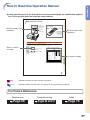
How to Read this Operation Manual
• In this operation manual, the illustrations and on-screen displays are simplified for explanation. This may differ from the actual on-screen display.
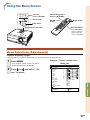
Using the Menu Screen
Adjustment
buttons ('/"/\/|)
ENTER button
Buttons used in this
operation
MOUSE/Adjustment
buttons ('/"/\/|)
ENTER
button
MENU button
MENU button
RETURN button
Buttons used in this
operation
RETURN button
• Press RETURN to
return to previous
screen when the
menu is displayed
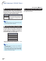
Menu Selections (Adjustments)
Example: Adjusting “Bright”.
• This operation can also be performed by using the buttons on the projector.
Button used in
this step
1
Press MENU.
2
Press | or \ and select “Picture” to adjust.
• The “Picture” menu screen for the selected input mode is displayed.
Example: “Picture” screen menu
Menu item
Picture
SIG
SCR
PRJ
Net.
Standard
0
0
0
0
0
0
0
SEL./ADJ.
RETURN
On-screen display
7500K
3D Progressive
Auto
Off
Off
Off
Useful Features
Picture Mode
Contrast
Bright
Color
Tint
Sharp
Red
Blue
CLR Temp
Progressive
Film Mode
DNR
MNR
Eco+Quiet Mode
Reset
ENTER
END
-43
Info ...........Indicates safeguards when using the projector.
Note ........Indicates additional information for setting up and operating the projector.
For Future Reference
Maintenance
Page 56
Troubleshooting
Pages 66 and 67
Index
Page 70
-3
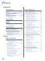
Contents
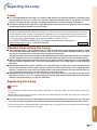
Preparing
Introduction
Useful Features
How to Read this Operation Manual ............. 3
Contents .......................................................... 4
How to Access the PDF Operation Manuals .... 6
IMPORTANT SAFEGUARDS .......................... 7
Accessories .................................................. 10
Part Names and Functions .......................... 12
Using the Remote Control ........................... 15
Menu Items ................................................... 40
Using the Menu Screen ............................... 43
Usable Range .................................................... 15
Inserting the Batteries ....................................... 15
Quick Start
Quick Start .................................................... 16
Setup
Setting Up the Projector .............................. 18
Setting Up the Projector .................................... 18
Projection (PRJ) Mode ....................................... 19
Connections
Samples of Cables for Connection ............. 21
Connecting to a Computer .......................... 23
Connecting to Video Equipment ................. 25
Controlling the Projector by a Computer ... 27
Connecting to a Monitor with RGB
Input Terminal ......................................... 28
Connecting to an Amplifier or Other
Audio Equipment .................................... 29
Using
Basic Operation
Turning the Projector On/Off ....................... 30
Connecting the Power Cord .............................. 30
Turning the Projector On .................................... 30
Turning the Power Off (Putting the Projector into
Standby Mode) ............................................ 30
Image Projection .......................................... 31
Using the Adjustment Feet ................................ 31
Correcting Trapezoidal Distortion ...................... 32
Adjusting the Lens ............................................. 33
Switching the Input Mode .................................. 34
Adjusting the Volume ......................................... 34
Displaying the Black Screen and Turning off
the Sound Temporarily ................................ 34
Displaying and Setting the Break Timer ............ 35
Switching the Eco+Quiet Mode ......................... 35
Auto Sync (Auto Sync Adjustment) ................... 35
Freezing a Moving Image .................................. 35
Selecting the Picture Mode ............................... 36
Displaying an Enlarged Portion of an Image .... 36
Resize Mode ...................................................... 37
Using the Remote Control as the Wireless
Computer Mouse ........................................ 39
-4
Menu Selections (Adjustments) ......................... 43
Picture Adjustment (“Picture” menu) ........ 45
Selecting the Picture Mode ............................... 45
Adjusting the Image .......................................... 45
Adjusting the Color Temperature ....................... 45
Selecting the Progressive Mode ........................ 46
Selecting the Film Mode .................................... 46
Reducing Image Noise (DNR) ........................... 46
Mosquito Noise Reduction (MNR) ..................... 46
Eco+Quiet Mode Setting ................................... 46
Signal Adjustment (“SIG-ADJ” Menu) ........ 47
Adjusting the Computer Image ......................... 47
Resolution Setting .............................................. 47
Auto Sync Adjustment ....................................... 47
Signal Type Setting ............................................ 47
Selecting the Dynamic Range ........................... 48
Setting the Video System ................................... 48
Checking the Input Signal ................................. 48
Screen Adjustment (“SCR-ADJ” Menu) ..... 49
Setting the Resize Mode ................................... 49
Adjusting the Image Position ............................. 49
Keystone Correction .......................................... 49
Setting the On-screen Display ........................... 50
Selecting a Startup and Background Image ..... 50
Selecting the Menu Screen Position .................. 50
Reversing/Inverting Projected Images .............. 50
Selecting the On-screen Display Language ..... 50
Helpful Functions Set during Installation
(“PRJ-ADJ” menu) ................................. 51
Auto Power Off Function .................................... 51
Auto Restart Function ........................................ 51
Setting the Confirmation Sound
(System Sound) ........................................... 51
Speaker Setting ................................................. 51
Audio Output Type Setting ................................ 51
Monitor Output ................................................... 51
LAN/RS232C ..................................................... 51
Selecting the Transmission Speed (RS-232C) .. 52
Fan Mode Setting .............................................. 52
System Lock Function ....................................... 52
Keylock Function ............................................... 53
Returning to the Default Settings ....................... 53
Checking the Lamp Life Status ......................... 53
Setting up the Projector Network
Environment (“Network” menu) ............ 54
Setting a Password ............................................ 54
DHCP Client Setting .......................................... 55
TCP/IP Setting ................................................... 55
Confirming the Projector Information ................. 55
Introduction
Reference
Appendix
Maintenance ................................................. 56
Replacing the Air Filter ................................ 57
Replacing the Air Filter ...................................... 57
Maintenance Indicators ............................... 59
Regarding the Lamp .................................... 61
Lamp ................................................................. 61
Caution Concerning the Lamp .......................... 61
Replacing the Lamp .......................................... 61
Removing and Installing the Lamp Unit ............ 62
Resetting the Lamp Timer ................................. 63
Storing the Projector ................................... 64
How to Use the Storage Case ........................... 64
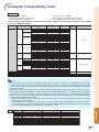
Computer Compatibility Chart .................... 65
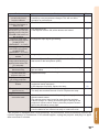
Troubleshooting ........................................... 66
For SHARP Assistance ................................ 68
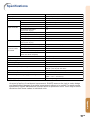
Specifications ............................................... 69
Index .............................................................. 70
SETUP MANUAL
Refer to the “SETUP MANUAL”
contained on the supplied CDROM for details.
Setting up the Screen .................................... 2
Screen Size and Projection Distance ........... 3
Changing the Lens ......................................... 9
Connecting Pin Assignments ..................... 11
RS-232C Specifications and Commands ... 13
Setting up the Projector Network
Environment ............................................ 18
Controlling the Projector via LAN .............. 24
Setting up the Projector Using
RS-232C or Telnet ................................... 29
Resetting the Lamp Timer
of the Projector via LAN ......................... 39
Troubleshooting ........................................... 41
Wired Remote Control Terminal
Specifications ......................................... 44
Dimensions ................................................... 45
-5
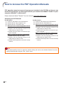
How to Access the PDF Operation Manuals
PDF operation manuals in several languages are included in the CD-ROM, so that you can
work with the projector. To utilize these manuals, you need to install Adobe® Reader ® on your
computer (Windows® or Macintosh®).
Please download Adobe® Reader ® from the Internet (http://www.adobe.com).
Accessing the PDF Manuals
For Windows®:
1 Insert the CD-ROM in the CD-ROM drive.
2 Double click the “My Computer” icon.
3 Double click the “CD-ROM” drive.
4 When you want to view the operation manual
1) Double click the “MANUALS” folder.
2) Double click the language (name of the
folder) that you want to view.
3) Double click the pdf file to access the projector manuals.
When you want to view the setup manual
1) Double click the “SETUP” folder.
2) Double click the language (name of the
folder) that you want to view.
3) Double click the pdf file to access the setup
manual.
For Macintosh®:
1 Insert the CD-ROM in the CD-ROM drive.
2 Double click the “CD-ROM” icon.
3 When you want to view the operation manual
1) Double click the “MANUALS” folder.
2) Double click the language (name of the
folder) that you want to view.
3) Double click the pdf file to access the projector manuals.
When you want to view the setup manual
1) Double click the “SETUP” folder.
2) Double click the language (name of the
folder) that you want to view.
3) Double click the pdf file to access the setup
manual.
Info
• If the desired pdf file cannot be opened by double clicking the mouse, start Adobe® Reader ® first, then
specify the desired file using the “File”, “Open” menu.
-6
Introduction
IMPORTANT SAFEGUARDS
CAUTION: Please read all of these instructions before you operate this product and save these
instructions for later use.
Electrical energy can perform many useful functions. This product has been engineered and manufactured to
assure your personal safety. BUT IMPROPER USE CAN RESULT IN POTENTIAL ELECTRICAL SHOCK OR
FIRE HAZARDS. In order not to defeat the safeguards incorporated in this product, observe the following basic
rules for its installation, use and servicing.
1. Read Instructions
All the safety and operating instructions should be read before
the product is operated.
2. Retain Instructions
The safety and operating instructions should be retained for
future reference.
3. Heed Warnings
All warnings on the product and in the operating instructions
should be adhered to.
4. Follow Instructions
All operating and use instructions should be followed.
5. Cleaning
Unplug this product from the wall outlet before cleaning. Do
not use liquid cleaners or aerosol cleaners. Use a damp cloth
for cleaning.
6. Attachments
Do not use attachments not recommended by the product
manufacturer as they may cause hazards.
7. Water and Moisture
Do not use this product near water–for example, near a bath
tub, wash bowl, kitchen sink, or laundry tub; in a wet
basement; or near a swimming pool; and the like.
8. Accessories
Do not place this product on an unstable cart, stand, tripod,
bracket, or table. The product may fall, causing serious injury
to a child or adult, and serious damage to the product. Use
only with a cart, stand, tripod, bracket, or table recommended
by the manufacturer, or sold with the product. Any mounting
of the product should follow the manufacturer’s instructions,
and should use a mounting accessory recommended by the
manufacturer.
9. Transportation
A product and cart combination should
be moved with care. Quick stops,
excessive force, and uneven surfaces
may cause the product and cart
combination to overturn.
10. Ventilation
Slots and openings in the cabinet are provided for ventilation
to ensure reliable operation of the product and to protect it
from overheating, and these openings must not be blocked
or covered. The openings should never be blocked by placing
the product on a bed, sofa, rug, or other similar surface. This
product should not be placed in a built-in installation such as
a bookcase or rack unless proper ventilation is provided or
the manufacturer’s instructions have been adhered to.
11. Power Sources
This product should be operated only from the type of power
source indicated on the marking label. If you are not sure of
the type of power supply to your home, consult your product
dealer or local power company. For products intended to
operate from battery power, or other sources, refer to the
operating instructions.
12. Grounding or Polarization
This product is provided with one of the following types of
plugs. If the plug should fail to fit into the power outlet,
please contact your electrician.
Do not defeat the safety purpose of the plug.
a. Two-wire type (mains) plug.
b. Three-wire grounding type (mains) plug with a
grounding terminal.
This plug will only fit into a grounding type power
outlet.
13. Power-Cord Protection
Power-supply cords should be routed so that they are not
likely to be walked on or pinched by items placed upon or
against them, paying particular attention to cords at plugs,
convenience receptacles, and the point where they exit from
the product.
14. Lightning
For added protection for this product during a lightning storm,
or when it is left unattended and unused for long periods of
time, unplug it from the wall outlet and disconnect the cable
system. This will prevent damage to the product due to
lightning and power-line surges.
15. Overloading
Do not overload wall outlets, extension cords, or integral
convenience receptacles as this can result in a risk of fire or
electric shock.
16. Object and Liquid Entry
Never push objects of any kind into this product through
openings as they may touch dangerous voltage points or
short-out parts that could result in a fire or electric shock.
Never spill liquid of any kind on the product.
17. Servicing
Do not attempt to service this product yourself as opening or
removing covers may expose you to dangerous voltage or
other hazards. Refer all servicing to qualified service
personnel.
18. Damage Requiring Service
Unplug this product from the wall outlet and refer servicing
to qualified service personnel under the following conditions:
a. When the power-supply cord or plug is damaged.
b. If liquid has been spilled, or objects have fallen into
the product.
c. If the product has been exposed to rain or water.
d. If the product does not operate normally by following
the operating instructions. Adjust only those controls
that are covered by the operating instructions, as an
improper adjustment of other controls may result in
damage and will often require extensive work by a
qualified technician to restore the product to normal
operation.
e. If the product has been dropped or damaged in any
way.
f. When the product exhibits a distinct change in
performance, this indicates a need for service.
19. Replacement Parts
When replacement parts are required, ensure that the service
technician has used replacement parts specified by the
manufacturer or have the same characteristics as the original
part. Unauthorized substitutions may result in fire, electric
shock, or other hazards.
20. Safety Check
Upon completion of any service or repairs to this product,
ask the service technician to perform safety checks to
determine that the product is in proper operating condition.
21. Wall or Ceiling Mounting
This product should be mounted to a wall or ceiling only as
recommended by the manufacturer.
22. Heat
This product should be situated away from heat sources such
as radiators, heat registers, stoves, or other products
(including amplifiers) that produce heat.
-7
IMPORTANT SAFEGUARDS
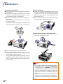
Ensure that you read the following safeguards when
setting up your projector.
Caution concerning the lamp unit
■ Potential hazard of glass particles if lamp ruptures. In case
of lamp rupture, contact your
nearest Sharp Authorized Projector Dealer or Service Center for replacement.
See “Regarding the Lamp” on
page 61.
■ When placing the projector in a high position, make certain it is carefully secured to
avoid personal injury caused by the projector falling down.
CAUTION
PRECAUCIÓN
PRÉCAUTION
Caution concerning the setup of the projector
■ For minimal servicing and to maintain high
image quality, SHARP recommends that this
projector be installed in an area free from humidity, dust and cigarette smoke. When the
projector is subjected to these environments,
the vents and lens must be cleaned more
often. As long as the projector is regularly
cleaned, use in these environments will not
reduce the overall operation life of the unit.
Internal cleaning should only be performed
by a Sharp Authorized Projector Dealer or
Service Center.
Do not set up the projector in places exposed to direct sunlight or bright light.
■ Position the screen so that it is not in direct
sunlight or room light. Light falling directly on
the screen washes out the colors, making
viewing difficult. Close the curtains and dim
the lights when setting up the screen in a
sunny or bright room.
The projector may be safely tilted to a
maximum angle of 9 degrees.
■ Placement should be within ±9 degrees of
horizontal.
When using the projector in high-altitude
areas such as mountains (at altitudes of
approximately 1,500 meters (4,900 feet)
or more)
■ When you use the projector in high-altitude
areas with thin air, set “Fan Mode” to “High”.
Neglecting this can affect the longevity of the
optical system.
-8
Warning about placing the projector in a
high position
Do not subject the projector to hard impact and/or vibration.
■ Take care with the lens so as not to hit or
damage the surface of the lens.
Rest your eyes occasionally.
■ Continuously watching the screen for long
hours will cause eye strain. Take regular
breaks to rest your eyes.
Avoid locations with extremes of temperature.
■ The operating temperature of the projector
is from 41°F to 95°F (+5°C to +35°C).
■ The storage temperature of the projector is
from –4°F to 140°F (–20°C to +60°C).
Do not block the intake and exhaust
vents.
■ Allow at least 7 7/8 inches (20 cm) of space
between the exhaust vent and the nearest
wall or obstruction.
■ Ensure that the intake vent and the exhaust
vent are not obstructed.
■ If the cooling fan becomes obstructed, a protection circuit will automatically put the projector into standby mode to prevent overheat
damage. This does not indicate a malfunction (see pages 59 and 60). Remove the projector power cord from the wall outlet and wait
at least 10 minutes. Place the projector where
the intake and exhaust vents are not blocked,
plug the power cord back in and turn on the
projector. This will return the projector to the
normal operating condition.
Introduction
Caution regarding usage of the projector
■ When using the projector, take care not to subject it to hard impact and/or vibration, as this
can result in damage. Take extra care with the
lens. If you are not to use the projector for a
long time, make certain you unplug the power
cord from the wall outlet, and disconnect any
other cables connected to it.
■ Do not carry the projector by holding the lens.
■ When storing the projector, ensure you attach
the lens cap to the projector. (See page 12.)
■ Do not expose the storage case or projector
to direct sunlight or near heat sources. The
storage case or projector may change color
or become deformed.
Info
• The cooling fan regulates the internal temperature, and its performance is automatically controlled. The sound of the fan may
change during projector operation due to
changes in the fan speed. This does not
indicate malfunction.
Other connected equipment
■ When connecting a computer or other audiovisual equipment to the projector, make the
connections AFTER unplugging the power
cord of the projector from the AC outlet and
turning off the equipment to be connected.
■ Please read the operation manuals of the projector and the equipment to be connected for
instructions on how to make the connections.
Using the projector in other countries
■ The power supply voltage and the shape of
the plug may vary depending on the region
or country you are using the projector in.
When using the projector overseas, make
sure you use an appropriate power cord for
the country you are in.
Temperature monitor function
■ If the projector starts to overheat due to setup problems
or blockage of the air vents,
“ ” and “
” will illuminate in the lower left corner of the picture. If the
temperature continues to rise, the lamp will turn
off, the temperature warning indicator on the
projector will blink, and after a 90-second cooling-off period the projector will enter the standby
mode. Refer to “Maintenance Indicators” on
page 59 for details.
-9
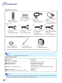
Accessories
Supplied accessories
Remote control
<RRMCGA623WJSA>
Power cord*
(1)
For U.S., Canada, etc.
(6' (1.8 m))
<QACCDA007WJPZ>
Two R-6 batteries
(“AA” size, UM/SUM-3,
HP-7 or similar)
(2)
RGB cable
(10' (3.0 m))
<QCNWGA086WJPZ>
(3)
For Europe, except U.K.
(6' (1.8 m))
<QACCVA011WJPZ>
DIN-D-sub RS-232C
adaptor
(5 57/64" (15 cm))
<QCNWGA091WJPZ>
(4)
For U.K., Hong Kong
and Singapore
(6' (1.8 m))
<QACCBA036WJPZ>
For Australia, New
Zealand and Oceania
(6' (1.8 m))
<QACCLA018WJPZ>
* Which power cords are supplied along with your projector depends on the region. Use the power cord
that corresponds to the wall outlet in your country.
Lens cap (attached)
<PCAPHA026WJSA>
Lens cap strap
<UBNDTA017WJZZ>
Storage case
<GCASNA020WJSA>
• Operation manual (this manual <TINS-E323WJZZ> and CD-ROM <UDSKAA119WJZZ>)
Note
• Codes in “< >” are Replacement parts codes.
Optional accessories
■ Lamp unit
■ Ceiling-mount adaptor
■ Ceiling-mount bracket
■ Universal bracket
■ Ceiling-mount unit
■ Ceiling-mount extension tube
■ Remote receiver
■ 3 RCA to 15-pin D-sub cable (10' (3.0 m))
AN-C430LP
AN-60KT
AN-XGCM55 (for U.S.A. only)
AN-JT200 (for U.S.A. only)
AN-TK201 <for AN-60KT>
AN-TK202 <for AN-60KT>
AN-EP101B <for AN-XGCM55 and AN-JT200>
(for U.S.A. only)
AN-MR2
AN-C3CP2
Note
• Some of the optional accessories may not be available depending on the region. Please check with your
nearest Sharp Authorized Projector Dealer or Service Center.
-10
Introduction
Optional lenses
■ Lens
Wide-zoom lens (× 1.5 – 1.9)
Tele-zoom lens (× 2.2 – 2.8)
Tele-zoom lens (× 3.3 – 5.1)
Tele-zoom lens (× 5.2 – 7.2)
AN-C12MZ
AN-C18MZ
AN-C27MZ
AN-C41MZ
Projection distance for 100" screen size
9'11" – 12'5" (3.0 m – 3.8 m)
14'10" – 18'10" (4.5 m – 5.7 m)
22' – 33'11" (6.7 m – 10.3 m)
34'5" – 48'4" (10.5 m – 14.7 m)
The standard zoom lens is attached to the projector.
The optional lenses from Sharp are also available for specialized application. Please see
your nearest Sharp Authorized Projector Dealer for details on all the lenses. (Refer to the
SETUP MANUAL on the supplied CD-ROM for details.) Also, be sure to have service personnel install the optional lenses.
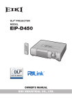
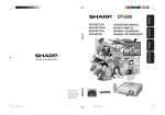
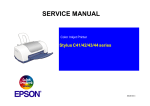
Throw Distance
The graph below is for 100 inches (254 cm) screen with 4:3 normal mode.
Screen
Wide-zoom lens (AN-C12MZ)
9'11"–12'5" (3.0 m–3.8 m)
Throw distance ratio 1:1.5–1.9
Standard zoom lens
11'9"–14'1" (3.6 m–4.3 m)
Throw distance ratio 1:1.8–2.1
Tele-zoom lens (AN-C18MZ)
14'10"–18'10" (4.5 m–5.7 m)
Throw distance ratio 1:2.2–2.8
Tele-zoom lens (AN-C27MZ)
22'–33'11" (6.7 m–10.3 m)
Throw distance ratio 1:3.3–5.1
Tele-zoom lens (AN-C41MZ)
34'5"–48'4" (10.5 m–14.7 m)
Throw distance ratio 1:5.2–7.2
3.0
6.0
9.1
12.2
10
20
30
40
15.2 (m)
50 (ft)
-11
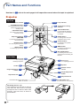
Part Names and Functions
Numbers in
refer to the main pages in this operation manual where the topic is explained.
Projector
Top View
Power indicator
STANDBY/ON button
30·59
30
For turning the power on and
putting the projector into
standby mode.
KEYSTONE button
32
30·59
59
Temperature warning
indicator
35
AUTO SYNC button
For automatically adjusting
images when connected to
a computer.
For entering the Keystone
Correction mode.
Adjustment buttons
('/"/\/|)
43
44
43
34
34
43
MENU button
For displaying adjustment
and setting screens.
For switching input mode.
35
ECO+QUIET button
For lowering the noise of the
cooling fan and extending the
lamp life.
Front View
Zoom knob
33
For enlarging/
reducing the picture.
Tilt dial
31
Height Adjustment
button
31
Adjustment foot
33
Attaching the lens cap
After putting the lens cap strap on the lens
cap, pass the other end of the strap
through the hole on the front side of the
projector, next to the lens, as shown in
the illustration.
Focus ring
For adjusting the focus.
51
Speaker
15
Remote control
sensor
31
Height Adjustment
button
31
Adjustment foot
31
Push both sides of the lens cap to
attach or remove.
-12
Volume buttons
For adjusting the speaker
sound level.
For returning to the previous
display.
INPUT buttons
ENTER button
For setting items selected
or adjusted on the menu.
For selecting and adjusting
on-screen items.
RETURN button
Lamp indicator
56·57
Air filter/Intake vent
(on the bottom of the projector)
Introduction
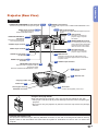
Projector (Rear View)
Terminals
COMPUTER/COMPONENT 2 input terminal
23·25
Terminal for Computer RGB and Component signals.
AUDIO input terminal
Audio input terminal for
COMPUTER/COMPONENT 1.
COMPUTER/COMPONENT 1
input terminal
25 AUDIO input terminal
Shared audio input terminal for COMPUTER/COMPONENT 2 and
DVI-D.
24·25 DVI-D input terminal
23·25
Terminal for DVI Digital RGB and Digital Component
signals.
28 LAN terminal
Terminal for controlling the
projector using a computer
via network.
23·25
Terminal for Computer RGB
and Component signals.
14 WIRED REMOTE terminal
S-VIDEO input terminal
26
VIDEO input terminal
26
For connecting the remote control
to the projector when the signals
from the remote control cannot
reach the remote control sensor.
27 RS-232C terminal
Terminal for controlling the
projector using a computer.
AUDIO input terminal
for S-video
26
AUDIO input terminal
for Video
26
39 USB terminal
Terminal connecting with the USB terminal on the
computer for using the supplied remote control as the
computer mouse.
29 AUDIO output terminal
MONITOR output terminal
28
Output terminal for Computer RGB and
Component signals.
Shared for COMPUTER/COMPONENT 1 and 2.
15 Remote control
sensor
56 Exhaust vent
Carrying handle
Intake vent
56
* Kensington Security
Standard connector
30 AC socket
Connect the supplied power cord.
Using the Carrying Handle
When transporting the projector, carry it by the carrying handle on the side.
• Always put on the lens cap to prevent damage to the lens when transporting the
projector.
• Do not lift or carry the projector by the lens or the lens cap as this may damage
the lens.
* Using the Kensington Lock
• This projector has a Kensington Security Standard connector for use with a Kensington MicroSaver Security
System. Refer to the information that came with the system for instructions on how to use it to secure the
projector.
-13
Part Names and Functions
Remote Control
STANDBY button
30
WIRED R/C JACK
For putting the projector into
standby mode.
KEYSTONE button
For controlling the projector by connecting
the remote control to the projector.
30
32
ENTER button
43
39·43
36
39·43
For enlarging/reducing part of the
image.
PAGE Up/Down buttons
39
Same as the [Page Down] and
[Page Up] keys on a computer
keyboard, when with the USB
connection (using a USB cable or
the optional remote receiver).
BREAK TIMER button
34
34
35
35
35
Volume buttons
AV MUTE button
FREEZE button
For freezing images.
36
37
34
35
RESIZE button
For switching the screen size
(NORMAL, STRETCH, etc.).
For switching the picture mode.
INPUT buttons
• For the Right click when with the
USB connection (using a USB
cable or the optional remote receiver).
• For returning to the previous
display.
For temporarily displaying the black
screen and turning off the sound.
For automatically adjusting images
when connected to a computer.
PICTURE MODE button
R-CLICK/RETURN button
For adjusting the speaker sound
level.
For displaying the break timer.
AUTO SYNC button
MOUSE/Adjustment buttons
('/"/\/|)
• For moving the computer cursor
when with the USB connection
(using a USB cable or the optional
remote receiver).
• For selecting and adjusting onscreen items.
39
For the Left click when with the
USB connection (using a USB
cable or the optional
remote receiver).
MAGNIFY (Enlarge/Reduce)
buttons
MENU button
For displaying adjustment and
setting screens.
44
For setting items selected or
adjusted on the menu.
L-CLICK button
ON button
For turning the power on.
For entering the Keystone
Correction mode.
ECO+QUIET button
For lowering the noise of the cooling
fan and extending the lamp life.
For switching to the respective
input modes.
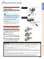
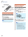
Using the Remote Control with a Signal Cable
When the signals from the remote control cannot be reached due to the positioning of the projector, use a
ø3.5 mm minijack cable to connect the remote control to the projector. Now you can control the projector
with the remote control.
Projector
(Rear view)
Remote control
To WIRED
REMOTE terminal
To WIRED
R/C JACK
ø3.5 mm minijack cable (commercially available or
available as Sharp service part QCNWGA038WJPZ)
Note
• The wireless remote function is not possible when the ø3.5 mm minijack cable is connected to the projector.
Should the wireless remote operation be required, the ø3.5 mm minijack cable should be disconnected
from the projector.
-14
Front View
Introduction
Using the Remote Control
Remote control sensor
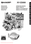
Usable Range
The remote control can be used to control the
projector within the ranges shown in the illustration.
30°
23' (7 m)
30°
30°
Note
• The signal from the remote control can be reflected off a screen for easy operation. However, the effective distance of the signal may
differ depending on the screen material.
Remote control
signal transmitters
Remote control
Rear View
Remote control sensor
30°
When using the remote control:
• Take care not to drop, expose to moisture or
high temperature.
• The remote control may malfunction under a
fluorescent lamp. In this case, move the projector away from the fluorescent lamp.
30°
23' (7 m)
30°
Remote control
signal transmitters
Remote control
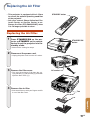
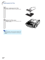
Inserting the Batteries
1
Pull down the tab on the cover and
remove the cover towards the direction of the arrow.
2
Insert the batteries.
3
Insert the lower tab of the cover
into the opening, and lower the
cover until it clicks in place.
• Insert the batteries making sure the poand
larities correctly match the
marks inside the battery compartment.
Incorrect use of the batteries may cause them to leak or explode. Please follow the precautions below.
Caution
• Danger of explosion if battery is incorrectly replaced. Replace only with alkaline or manganese batteries.
and
marks inside the battery compart• Insert the batteries making sure the polarities correctly match the
ment.
• Batteries of different types have different properties, therefore do not mix batteries of different types.
• Do not mix new and old batteries.
This may shorten the life of new batteries or may cause old batteries to leak.
• Remove the batteries from the remote control once they have run out, as leaving them in can cause them to leak.
Battery fluid from leaked batteries is harmful to skin, therefore ensure you wipe them first and then remove them
using a cloth.
• The batteries included with this projector may run down in a short period, depending on how they are kept. Be
sure to replace them as soon as possible with new batteries.
• Remove the batteries from the remote control if you will not be using the remote control for a long time.
• Comply with the rules (ordinance) of each local government when disposing of worn-out batteries.
-15
Quick Start
This section shows the basic operation (projector connecting with the computer). For details, see the page
described below for each step.
Setup and Projection
In this section, connection of the projector and the computer is explained using one example.
3 7 STANDBY/ON button
7 STANDBY
button
6 INPUT buttons
3 ON button
6 ENTER button
5 Zoom knob
5 Focus ring
6 COMPUTER 1
button
4 Tilt dial
4 Height Adjustment buttons
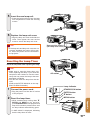
1. Place the projector facing a screen
Page 18
2. Connect the projector to the computer and plug the power
cord into the AC socket of the projector
When connecting equipment other than the computer, see pages 25, 28 and 29.
Pages 23, 30
3. Remove the lens cap and turn the projector on
On the projector
On the remote control
Page 30
-16
4. Adjust the angle
• This projector is equipped with an “Auto V-Keystone
Correction” function that automatically corrects any
trapezoidal distortion within the projected image.
Adjust the projector angle
• Adjust the projector angle using the Height
Adjustment buttons.
• Rotate the Tilt dial to adjust the horizontal tilt of
the projector.
Quick Start
Height Adjustment
buttons
Tilt dial
Pages 31, 32
5. Adjust the focus and the zoom
Bring the projected image into focus
• Bring the projected image into focus by
rotating the focus ring.
Adjust the projected image size
• Adjust the projected image size by moving the
zoom knob.
Focus ring
Zoom knob
ut
mo
Zoo
m in
Zoo
Page 33
6. Select the INPUT mode
Select the “COMPUTER 1” using the INPUT buttons on the projector or the COMPUTER 1 button on the remote control.
On the
projector
On the remote
control
" INPUT list
INPUT
COMPUTER1
" On-screen Display (RGB)
COMPUTER1
RGB
1024 × 768
COMPUTER2
D
DVI-D Computer
• When you press the INPUT buttons on the projector, the INPUT list appears.
" to select an item on the list, and press ENTER to switch to the selected INPUT mode.
Press '/"
• When using the remote control, press COMPUTER1/2, DVI, S-VIDEO or VIDEO to
switch the INPUT mode.
Page 34
7. Turn the Power off
Press the STANDBY button, then press that button again while the confirmation message is displayed, to put the projector into standby mode.
" On-screen Display
On the projector
On the remote control
• Even if you unplug the power cord from the AC outlet, the cooling fan continues to run for a while.
Page 30
-17
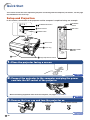
Setting Up the Projector
Setting Up the Projector
For optimal image quality, position the projector perpendicular to the screen with the projector’s feet flat
and level. Doing so will eliminate the need for Keystone correction and provide the best image quality. (See
page 32.)
Standard Setup (Front Projection)
■ Place the projector at the required distance from the screen according
to the desired picture size. (For details, refer to the “SETUP MANUAL” contained on the supplied CD-ROM.)
Example of standard setup
Side View
Base line:
Horizontal line passing through
the lens center
Screen
Lens center
H
L: Projection distance
Ceiling-mount Setup
■ It is recommended that you use the optional Sharp ceiling-mount adaptor and unit for this installation. Before
mounting the projector, contact your nearest Sharp Authorized Projector Dealer or Service Center to obtain the
recommended ceiling-mount adaptor and unit (sold separately).
-18
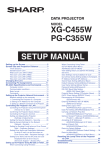
Projection (PRJ) Mode
The projector can use any of the 4 projection modes, shown in the diagram below. Select the mode most appropriate for the projection setting in use. (You can set the PRJ mode in “SCR-ADJ” menu. See page 50.)
■ Ceiling mounted, front projection
[Menu item ➞ “Ceiling + Front”]
■ Table mounted, rear projection
(with a translucent screen)
[Menu item ➞ “Rear”]
■ Ceiling mounted, rear projection
(with a translucent screen)
[Menu item ➞ “Ceiling + Rear”]
Setup
■ Table mounted, front projection
[Menu item ➞ “Front”]
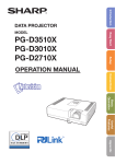
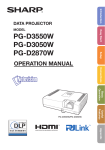
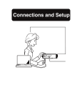
Indication of the Projection Image Size and Projection Distance
For details, refer to the “SETUP MANUAL” contained on the supplied CD-ROM.
Example: NORMAL Mode (4:3) for standard lens
Picture Size
500"
400"
×300
"
200"
160
"×12
80"×
67"× 60"
50"
48"×
36"
0"
Pro
ject
7'
(2 0"–
.1 8
9' m – '5"
(3 10 2.6
.0 "– m
m 11 )
11 – 3 '10
(3 '9 .6 m "
.6 "– )
m 14
23 – 4. '1"
(7 '5 3 m
.1 "– )
m 28
– '1
8. "
6
58 m)
'
(1 7
7. "–
9 7
m 0
– '4"
21
.4
m
)
100"
84"
60"
ion
Dist
anc
e
-19
Setting Up the Projector
Standard Zoom Lens
F1.7-F1.9, f=28.0-33.6 mm
NORMAL Mode (4:3)
Picture (Screen) size
Diag. [χ]
500''
300''
270''
250''
200''
150''
100''
84''
80''
72''
60''
40''
χ:
L:
L1:
L2:
H:
(1270 cm)
(762 cm)
(686 cm)
(635 cm)
(508 cm)
(381 cm)
(254 cm)
(213 cm)
(203 cm)
(183 cm)
(152 cm)
(102 cm)
Width
1016 cm
610 cm
549 cm
508 cm
406 cm
305 cm
203 cm
171 cm
163 cm
146 cm
122 cm
81 cm
(400'')
(240'')
(216'')
(200'')
(160'')
(120'')
(80'')
(67'')
(64'')
(58'')
(48'')
(32'')
Projection distance [L]
Height
762 cm
457 cm
411 cm
381 cm
305 cm
229 cm
152 cm
128 cm
122 cm
110 cm
91 cm
61 cm
(300'')
(180'')
(162'')
(150'')
(120'')
(90'')
(60'')
(50'')
(48'')
(43'')
(36'')
(24'')
Minimum [L1]
17.9 m
10.7 m
9.6 m
8.9 m
7.1 m
5.4 m
3.6 m
3.0 m
2.9 m
2.6 m
2.1 m
1.4 m
(58' 7")
(35' 2")
(31' 8")
(29' 3")
(23' 5")
(17' 7")
(11' 9")
(9' 10")
(9' 4")
(8' 5")
(7')
(4' 8")
Maximum [L2]
21.4 m
12.9 m
11.6 m
10.7 m
8.6 m
6.4 m
4.3 m
3.6 m
3.4 m
3.1 m
2.6 m
1.7 m
(70' 4")
(42' 2")
(38')
(35' 2")
(28' 1")
(21' 1")
(14' 1")
(11' 10")
(11' 3")
(10' 1")
(8' 5")
(5' 7")
Picture size (diag.) (in/cm)
Projection distance(m/ft)
Minimum projection distance (m/ft)
Maximum projection distance (m/ft)
Distance from the lens center to the bottom of the image (cm/in)
Distance from the lens center
to the bottom of the image [H]
–76 cm
–46 cm
–41 cm
–38 cm
–30 cm
–23 cm
–15 cm
–13 cm
–12 cm
–11 cm
–9 cm
–6 cm
(–30")
(–18")
(–16 13/64")
(–15")
(–12")
(–9")
(–6")
(–5 3/64")
(–4 51/64")
(–4 5/16")
(–3 19/32")
(–2 13/32")
The formula for picture size and projection distance
[m/cm]
L1 (m) = 0.03571χ
L2 (m) = 0.04286χ
H (cm) = –0.1524χ
[Feet/inches]
L1 (ft) = 0.03571χ / 0.3048
L2 (ft) = 0.04286χ / 0.3048
H (in) = –0.1524χ / 2.54
STRETCH Mode (16:9)
Picture (Screen) size
Diag. [χ]
450''
300''
250''
225''
200''
150''
133''
106''
100''
92''
84''
80''
72''
60''
40''
χ:
L:
L1:
L2:
H:
S:
(1143 cm)
(762 cm)
(635 cm)
(572 cm)
(508 cm)
(381 cm)
(338 cm)
(269 cm)
(254 cm)
(234 cm)
(213 cm)
(203 cm)
(183 cm)
(152 cm)
(102 cm)
Width
996 cm
664 cm
553 cm
498 cm
443 cm
332 cm
294 cm
235 cm
221 cm
204 cm
186 cm
177 cm
159 cm
133 cm
89 cm
(392'')
(261'')
(218'')
(196'')
(174'')
(131'')
(116'')
(92'')
(87'')
(80'')
(73'')
(70'')
(63'')
(52'')
(35'')
Projection distance [L]
Height
560 cm
374 cm
311 cm
280 cm
249 cm
187 cm
166 cm
132 cm
125 cm
115 cm
105 cm
100 cm
90 cm
75 cm
50 cm
(221'')
(147'')
(123'')
(110'')
(98'')
(74'')
(65'')
(52'')
(49'')
(45'')
(41'')
(39'')
(35'')
(29'')
(20'')
Minimum [L1]
17.5 m
11.7 m
9.7 m
8.8 m
7.8 m
5.8 m
5.2 m
4.1 m
3.9 m
3.6 m
3.3 m
3.1 m
2.8 m
2.3 m
1.6 m
(57' 5")
(38' 3")
(31' 11")
(28' 9")
(25' 6")
(19' 2")
(17')
(13' 6")
(12' 9")
(11' 9")
(10' 9")
(10' 3")
(9' 2")
(7' 8")
(5' 1")
Picture size (diag.) (in/cm)
Projection distance(m/ft)
Minimum projection distance (m/ft)
Maximum projection distance (m/ft)
Distance from the lens center to the bottom of the image (cm/in)
Adjustable range of image position (cm/in)
Maximum [L2]
21.0 m
14.0 m
11.7 m
10.5 m
9.3 m
7.0 m
6.2 m
4.9 m
4.7 m
4.3 m
3.9 m
3.7 m
3.4 m
2.8 m
1.9 m
(68' 11")
(45' 11")
(38' 4")
(34' 6")
(30' 8")
(23')
(20' 4")
(16' 3")
(15' 4")
(14' 1")
(12' 10")
(12' 3")
(11')
(9' 2")
(6' 2")
Distance from the lens center
to the bottom of the image [H]
19 cm
12 cm
10 cm
9 cm
8 cm
6 cm
6 cm
4 cm
4 cm
4 cm
3 cm
3 cm
3 cm
2 cm
2 cm
(7 23/64")
(4 29/32")
(4 5/64")
(3 43/64")
(3 17/64")
(2 29/64")
(2 11/64")
(1 47/64")
(1 41/64")
(1 1/2")
(1 3/8")
(1 5/16")
(1 11/64")
(63/64")
(21/32")
Adjustable range of
image position [S]
±93 cm
±62 cm
±52 cm
±47 cm
±42 cm
±31 cm
±28 cm
±22 cm
±21 cm
±19 cm
±17 cm
±17 cm
±15 cm
±12 cm
±8 cm
(±36 49/64")
(±24 33/64")
(±20 27/64")
(±18 25/64")
(±16 11/32")
(±12 1/4")
(±10 7/8")
(±8 21/32")
(±8 11/64")
(±7 33/64")
(±6 55/64")
(±6 17/32")
(±5 57/64")
(±4 29/32")
(±3 17/64")
The formula for picture size and projection distance
[m/cm]
L1 (m) = 0.0389χ
L2 (m) = 0.04669χ
H (cm) = 0.04151χ
S (cm) = ±0.20754χ
[Feet/inches]
L1 (ft) = 0.0389χ / 0.3048
L2 (ft) = 0.04669χ / 0.3048
H (in) = 0.04151χ / 2.54
S (in) = ±0.20754χ / 2.54
Note
• Allow a margin of error in the value in the diagrams above.
• When the distance from the lens center to the bottom of the image [H] is a negative number, this indicates
that the bottom of the image is below the lens center.
• See page 18 about projection distance [L] and distance from the lens center to the bottom of the image [H].
-20
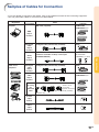
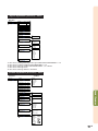
Samples of Cables for Connection
• For more details of connection and cables, refer to the operation manual of the connecting equipment.
• You may need other cables or connectors not listed below.
Equipment
Terminal on
connected equipment
Computer
Cable
Terminal on the
projector
RGB cable (supplied)
COMPUTER/
COMPONENT 1, 2
DVI Digital cable (commercially available)
DVI-D
ø3.5 mm stereo or mono audio cable (commercially
available or available as Sharp service part
QCNWGA038WJPZ)
AUDIO
(for COMPUTER/
COMPONENT 1, 2, DVI-D)
DVI Digital cable (commercially available)
DVI-D
3 RCA to 15-pin D-sub cable (optional: AN-C3CP2)
COMPUTER/
COMPONENT 1, 2
RGB
output
terminal
DVI digital
video
output
terminal
Audio-visual
equipment
DVI digital
video
output
terminal
Component
video
output
terminal
Connections
Audio
output
terminal
Terminal Connect with the cable adaptor, etc.
for using
3 RCA to 15-pin
the
D-sub cable
(optional: AN-C3CP2)
dedicated
cable
Cable adaptor (commercially available)
Dedicated cable
S-video
output
terminal
Video
output
terminal
S-video cable (commercially available)
S-VIDEO
Video cable (commercially available)
VIDEO
-21
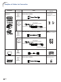
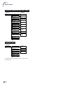
Samples of Cables for Connection
Equipment
Audio-visual
equipment
Terminal on
connected equipment
Audio
output
terminal
Terminal on the
projector
Cable
ø3.5 mm stereo minijack to RCA audio cable
(commercially available)
AUDIO
(for COMPUTER/
COMPONENT 1, 2, DVI-D)
Terminal Connect with the cable adaptor, etc.
for using
Cable adaptor
the
(commercially available)
dedicated
cable
Dedicated cable
ø3.5 mm stereo minijack to RCA audio
cable (commercially available)
RCA audio cable (commercially available)
Audio
output
terminal
AUDIO
(for VIDEO, S-VIDEO)
Terminal Connect with the cable adaptor, etc.
for using
the
Cable adaptor
(commercially available)
dedicated
cable
Dedicated cable
RCA audio cable
(commercially available)
Monitor
RGB cable (supplied or commercially available)
MONITOR OUTPUT
ø3.5 mm stereo minijack to RCA audio cable
(commercially available)
AUDIO
(MONITOR OUT)
RGB
input
terminal
Amplifier
Audio
input
terminal
-22
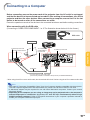
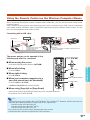
Connecting to a Computer
Before connecting, ensure the power cord of the projector from the AC outlet is unplugged,
and that the devices to be connected are turned off. After making all connections, turn on the
projector and then the other devices. When connecting a computer, ensure that it is the last
device to be turned on after all the connections are made.
Ensure the operation manuals of the devices to be connected have been read before making connections.
When connecting with the RGB cable
(Connecting to COMPUTER/COMPONENT 1 or 2: The illustration shown below is for the former.)
Supplied
accessory
RGB cable
Computer
To audio output terminal
To COMPUTER/
COMPONENT 1
input terminal
To RGB output terminal
To AUDIO input terminal
Connections
RGB cable
* ø3.5 mm stereo or mono audio cable
(commercially available or available as Sharp service part QCNWGA038WJPZ)
* When using the ø3.5 mm mono audio cable, the volume level will be half of when using the ø3.5 mm stereo audio cable.
Note
• See page 65 “Computer Compatibility Chart” for a list of computer signals compatible with the projector.
Use with computer signals other than those listed may cause some of the functions to not work.
• A Macintosh adaptor may be required for use with some Macintosh computers. Contact your nearest
Macintosh Dealer.
• Depending on the computer you are using, an image may not be projected unless the computer’s
external output port is switched on. (e.g. Press “Fn” and “F5” keys simultaneously when using a
SHARP notebook computer). Refer to the specific instructions in your computer’s operation manual to
enable your computer’s external output port.
-23
Connecting to a Computer
When connecting with a DVI digital cable
The projector employs the DVI digital input terminal for direct input of Digital Video signals from a
computer.
Computer
To AUDIO input terminal
(for DVI-D)
To DVI-D input terminal
To DVI digital
output terminal
To audio output
terminal
DVI Digital cable
(commercially available)
* ø3.5 mm stereo or mono audio cable
(commercially available or available as
Sharp service part QCNWGA038WJPZ)
* When using the ø3.5 mm mono audio cable, the volume level will be half of when using the ø3.5 mm stereo audio cable.
-24
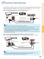
Connecting to Video Equipment
The image quality is highest in order of the Component signal, the RGB signal, the S-video signal and the
Video signal. If your audio-visual equipment has a component output terminal or RGB output terminal, use the
COMPUTER/COMPONENT terminal 1 or 2 on the projector for video connection.
When connecting video equipment with a DVI output terminal
Video Equipment
To audio output terminals
To AUDIO input terminal
(for COMPUTER/COMPONENT 2, DVI-D)
To DVI-D
input terminal
ø3.5 mm stereo minijack to RCA audio cable
(commercially available)
DVI Digital cable (commercially available)
To DVI output terminal
Note
Connections
• Select the input signal type of the video equipment. See page 47.
• While the projector is connected to video equipment that has an HDMI output terminal, only the video
signal can be input to the projector. (Connect the AUDIO input terminal for audio input.)
• Depending on specifications of video equipment or HDMI to DVI digital cable, the signal transmission
may not work property. (The HDMI specification does not support all connections to video equipment
that has HDMI digital output terminal using HDMI to DVI digital cable.)
• For details on compatibility for connection, see support information on DVI connection provided by the
video equipment manufacturer.
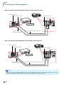
When connecting video equipment with component video output terminal
(Connecting to COMPUTER/COMPONENT 1 or 2: The illustration shown below is for the former.)
Video Equipment
To audio output terminal
To component video output terminal
To COMPUTER/COMPONENT 1
input terminal
To AUDIO
input terminal
3 RCA (Component) to 15-pin D-sub cable
(optional: AN-C3CP2)
ø3.5 mm minijack to RCA audio cable (commercially available)
Note
• When you connect video equipment with a 21-pin RGB output (Euro-scart) to the projector, use a
commercially available cable that fits in the projector terminal you want to connect.
• The projector does not support RGBC signals via the Euro-scart.
-25
Connecting to Video Equipment
When connecting video equipment with S-video output terminal
To audio output terminal
To S-VIDEO input terminal
To S-video output terminal
To AUDIO input terminal
Video Equipment
RCA audio cable
(commercially available)
S-video cable (commercially available)
When connecting video equipment with video output terminal
To audio output terminal
To video output terminal
To VIDEO input terminal
To AUDIO input terminal
Video Equipment
RCA audio cable
(commercially available)
Composite video cable (commercially available)
Note
• When you connect video equipment with a 21-pin RGB output (Euro-scart) to the projector, use a commercially available cable that fits in the projector terminal you want to connect.
-26
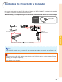
Controlling the Projector by a Computer
When the RS-232C terminal on the projector is connected to a computer, the computer can be used to control
the projector and check the status of the projector. Refer to the “SETUP MANUAL” contained on the supplied
CD-ROM for “RS-232C Specifications and Commands”.
When connecting to a computer using an RS-232C serial control cable and a DIN-D-sub RS-232C adaptor
Supplied
accessory
Computer
DIN-D-sub
RS232C adaptor
To RS-232C terminal
To RS-232C terminal
DIN-D-sub
RS-232C adaptor
Connections
RS-232C serial control cable (cross type, commercially available)
Note
• The RS-232C function may not operate if your computer terminal is not correctly set up. Refer to the
operation manual of the computer for details.
Info
• Do not connect the RS-232C cable to a port other than the RS-232C terminal on the computer. This may
damage your computer or projector.
• Do not connect or disconnect an RS-232C serial control cable to or from the computer while it is on. This
may damage your computer.
-27
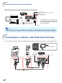
Controlling the Projector by a Computer
When connecting to the LAN terminal using a LAN cable
TX/RX LED (yellow)
Illuminates when transmitting/receiving data.
LINK LED (green)
Illuminates when linked.
HUB
or
* To ensure safety, do not connect the
LAN terminal with any cables such
as a telephone line that may cause
excessive voltage.
Computer
LAN cable (Category 5 type, commercially available)
To LAN terminal
Note
• When connecting to hub, use straight-through Category 5 (CAT.5) type cable (commercially available).
• When connecting to computer, use cross-over Category 5 (CAT.5) type cable (commercially available).
Connecting to a Monitor with RGB Input Terminal
You can display computer images on both the projector and a separate monitor using two sets of RGB cables.
Supplied
accessory
Computer
Monitor
To COMPUTER/
COMPONENT 1
input terminal
To RGB input terminal
To RGB output
terminal
RGB cable
RGB cable (commercially available)
-28
RGB cable
To MONITOR OUT terminal
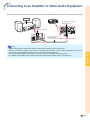
Connecting to an Amplifier or Other Audio Equipment
Audio signals input from equipment connected to each audio input terminal of the projector can be output to audio equipment.
Amplifier
To AUDIO output terminal
(MONITOR OUT)
To audio input terminal
ø3.5 mm minijack to
RCA audio cable
(commercially available)
Note
Connections
• Turn off the power of both the projector and audio equipment when connecting.
• When turning off the power in the case of connecting an amplifier or other audio equipment, first turn off
the power of the amplifier and then turn off the power of the projector.
• By using external audio components, the volume can be amplified for better sound.
• For details on Variable Audio Output (VAO) and Fixed Audio Output (FAO), see page 52.
-29
Turning the Projector On/Off
Connecting the Power Cord
Supplied
accessory
Power cord
Plug the supplied power cord into the AC
socket on the rear of the projector. Then plug
into the AC outlet.
Turning the Projector On
Before performing the steps in this section,
connect any equipment that you use with the
projector. (See pages 23-29.)
Remove the lens cap and press
STANDBY/ON on the projector or ON
on the remote control.
• The power indicator illuminates green.
• After the lamp indicator illuminates, the projector is ready to start operation.
Note
• The lamp indicator illuminates or blinks, indicating the status of the lamp.
Green: The lamp is on.
Blinking green: The lamp is warming up.
Red: The lamp is shut down abnormally or the lamp should be
replaced.
• When switching on the projector, a slight flickering of the image may be experienced within the
first minute after the lamp has been illuminated.
This is normal operation as the lamp's control
circuitry is stabilizing the lamp output characteristics. This does not indicate malfunction.
• If the projector is put into standby mode and
immediately turned on again, the lamp may
take some time to illuminate.
• When System Lock is set, the keycode input box appears. To cancel the keycode setting, input the keycode that you have already
set. See page 52 for details.
Turning the Power Off
(Put-
AC socket
To AC outlet
Info
• When “Auto Restart” is set to “On”:
If the power cord is unplugged from the outlet or the
breaker switch is turned off when the projector is on, then
the projector automatically turns on when the power cord
is plugged into the AC outlet or the breaker switch is turned
on. (See page 51.)
• English is the factory preset language. If you want to
change the on-screen display to another language, change
the language according to the procedure on page 50.
Power indicator
Lamp
indicator
STANDBY/ON button
ON button
STANDBY
button
▼On-screen Display
ting the Projector into Standby Mode)
Press STANDBY/ON on the projector or
STANDBY on the remote control, then press
that button again while the confirmation message is displayed, to put the projector into
standby mode.
Info
• Direct Power Off function:
You can unplug the power cord from the AC outlet
even if the cooling fan is still running.
-30
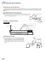
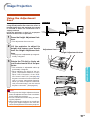
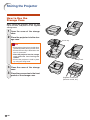
Image Projection
Using the Adjustment
Feet
The height of the projector can be adjusted
using the adjustment feet when the screen is
located higher than the projector, the screen
is inclined or when the installation site is
slightly inclined.
Install the projector so that it is as perpendicular to the screen as possible.
1
Top View
Side View
Lens
center
Press the Height Adjustment buttons.
• The adjustment feet come out.
2
Lift the projector to adjust its
height and remove your hands
from the Height Adjustment buttons.
Adjustment foot
Height Adjustment button
• The projector is adjustable up to approximately 9 degrees.
3
Rotate the Tilt dial to finely adjust the horizontal tilt of the projector.
Basic Operation
• The inclination is adjustable within approximately 2 degrees.
• When adjusting the height of the projector, trapezoidal distortion occurs.
When “Auto V-Keystone” of the “SCRADJ” menu is set to “On” (see page 49),
keystone correction functions automatically to correct trapezoidal distortion.
When you want to adjust the automatically corrected image, use the manual
keystone correction. (See page 32.)
Info
• Do not press the Height Adjustment button
when the adjustment feet come out without
firmly holding the projector.
• Do not hold the lens when lifting or lowering the projector.
• When lowering the projector, be careful not
to get your fingers caught in the area between the adjustment foot and the projector.
Tilt dial
-31
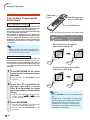
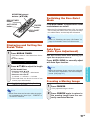
Image Projection
Correcting Trapezoidal
Distortion
KEYSTONE
button
MOUSE/Adjustment
buttons ('/"/\/|)
Auto V-Keystone Correction
When the image is projected either from the top
or from the bottom towards the screen at an angle,
the image becomes distorted trapezoidally.
The function for correcting trapezoidal distortion
is called Keystone Correction.
This projector is equipped with an “Auto V-Keyst