1
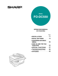
MODEL
AR-M162
AR-M207
DIGITAL MULTIFUNCTIONAL
SYSTEM
OPERATION MANUAL
(for general information and copier)
Page
PART 1: GENERAL INFORMATION
• BEFORE USING
THE PRODUCT
• TROUBLESHOOTING
AND MAINTENANCE
• PERIPHERAL DEVICES
AND SUPPLIES
12
24
40
PART 2: COPIER OPERATION
AR-M162
• COPY FUNCTIONS
• CONVENIENT COPY
FUNCTIONS
• APPENDIX
45
64
73
Be sure to become thoroughly familiar with this manual to
gain the maximum benefit from the product.
Before installing this product, be sure to read the
cautions and installation requirements sections.
AR-M207
With the RSPF installed
Be sure to keep all operation manuals handy for reference
including this manual, the "Operation manual (for general
information and copier)" and operation manuals for any
optional equipment which has been installed.
Caution:
For complete electrical disconnection, pull out the main plug.
The socket-outlet should be installed near the equipment and should be easily accessible.
FOR YOUR RECORDS ...
To protect against loss or theft, record and retain for reference the
machine's serial number located on the back of the unit.
Model Number
Serial Number
Date of Purchase
Place of Purchase
Authorized Sharp Copier
Service Department Number
WARNING:
FCC Regulations state that any unauthorized changes or modifications to this equipment
not expressly approved by the manufacturer could void the user's authority to operate this
equipment.
This operation manual is also used for the AR-M162 J / AR-M207 J.
Part 1: General Information
1
2
Notes
• Considerable care has been taken in preparing this manual. If you have any comments or concerns about the
manual, please contact your nearest SHARP Service Department.
• This product has undergone strict quality control and inspection procedures. In the unlikely event that a defect or
other problem is discovered, please contact your dealer or nearest SHARP Service Department.
• Aside from instances provided for by law, SHARP is not responsible for failures occurring during use of the product
or its options, or failures due to incorrect operation of the product and its options, or other failures, or for any
damage that occurs due to use of the product.
The display screens, messages, and key names shown in the manual may differ from those on the actual machine due to
product improvements and modifications.
PRODUCT CONFIGURATIONS
This product series consists of the models indicated below. The product configuration varies by model.
The explanations and illustrations in this manual generally use the AR-M207 (with the optional RSPF installed).
Model
Appearance
Copying speed
Paper trays
Optional trays
250-sheet paper
feed unit (AR-D24)
AR-M162
16 copies/min.
One (250 x 1)
2 x 250-sheet paper
feed unit (AR-D25)
AR-M207
20 copies/min.
Two (250 x 2)
With the RSPF installed
(As of the end of October, 2004)
3
CONTENTS
Part 1: General Information
PRODUCT CONFIGURATIONS ................................................................................................................ 3
CAUTIONS................................................................................................................................................. 6
● CAUTIONS ON USING..................................................................................................................................... 6
● LASER INFORMATION .................................................................................................................................... 7
INSTALLATION REQUIREMENTS ........................................................................................................... 8
● ENVIRONMENTAL INFORMATION................................................................................................................. 8
MANUALS PROVIDED WITH THE PRODUCT......................................................................................... 9
MAIN FEATURES .................................................................................................................................... 10
1
BEFORE USING THE PRODUCT
2
TROUBLESHOOTING AND MAINTENANCE
PART NAMES AND FUNCTIONS ................... 12
TROUBLESHOOTING..................................... 25
● OPERATION PANEL ......................................14
● OPERATION IN COPY, PRINT, SCAN, AND
FAX MODES...................................................16
● MACHINE/COPYING PROBLEMS ................ 25
TURNING THE POWER ON AND OFF ........... 17
● POWER ON ....................................................17
● POWER OFF ..................................................17
LOADING PAPER............................................ 18
● PAPER............................................................18
● LOADING PAPER...........................................19
● CHANGING THE PAPER SIZE SETTING OF A
TRAY ..............................................................21
● DISABLING (ENABLING) AUTO TRAY
SWITCHING ...................................................22
AUDITING MODE ............................................ 23
● NUMBER OF ACCOUNTS IN AUDITING
MODE .............................................................23
● USING AUDITING MODE...............................23
INDICATORS AND DISPLAY MESSAGES .... 28
REMOVING MISFEEDS .................................. 29
●
●
●
●
●
ORIGINAL MISFEED IN THE SPF ................ 29
MISFEED IN THE BYPASS TRAY ................ 30
MISFEED IN THE MACHINE......................... 31
MISFEED IN TRAY 1 ..................................... 33
MISFEED IN TRAY 2 ..................................... 34
REPLACING THE TONER CARTRIDGE ........ 35
CHECKING THE TOTAL OUTPUT COUNT ... 36
CLEANING THE MACHINE............................. 37
● CLEANING THE DOCUMENT GLASS AND
SPF/DOCUMENT COVER............................. 37
● CLEANING THE BYPASS TRAY PAPER FEED
ROLLER......................................................... 37
● CLEANING THE TRANSFER CHARGER ..... 38
ADJUSTING THE DISPLAY CONTRAST....... 39
3
PERIPHERAL DEVICES AND SUPPLIES
OPTIONAL EQUIPMENT ................................ 40
● REVERSING SINGLE PASS FEEDER /
SINGLE PASS FEEDER................................ 41
● 250-SHEET PAPER FEED UNIT / 2 X
250-SHEET PAPER FEED UNIT................... 41
● DUAL FUNCTION BOARD ............................ 42
STORAGE OF SUPPLIES............................... 42
● PROPER STORAGE ..................................... 42
4
CONTENTS
Part 2: Copier Operation
4
COPY FUNCTIONS
NORMAL COPYING ........................................ 45
●
●
●
●
●
6
APPENDIX
SPECIFICATIONS ........................................... 73
MAKING A COPY DARKER OR LIGHTER ....48
SELECTING THE TRAY.................................49
SETTING THE NUMBER OF COPIES ...........49
SELECTING THE ORIGINAL SIZE ................50
USING THE BYPASS TRAY TO COPY A
SPECIAL SIZE ORIGINAL..............................51
MATERIAL SAFETY DATA SHEET................ 75
REDUCING OR ENLARGING A COPY........... 52
INDEX .............................................................. 83
● AUTOMATIC RATIO SELECTION .................52
● MANUAL RATIO SELECTION (PRESET COPY
RATIOS/ZOOM)..............................................52
SELECTING THE VERTICAL AND
HORIZONTAL COPY RATIOS SEPARATELY
(XY zoom copying) ......................................... 54
TWO-SIDED COPYING ................................... 56
● TWO-SIDED COPYING..................................56
● TWO-SIDED COPYING OF ONE-SIDED
ORIGINALS ....................................................57
● TWO-SIDED COPIES OF TWO-SIDED ORIGINALS
(ONLY WHEN USING THE RSPF) ......................59
● ONE-SIDED COPIES OF TWO-SIDED ORIGINALS
(ONLY WHEN USING THE RSPF) ......................60
TWO-SIDED COPIES USING THE BYPASS TRAY... 61
DUAL PAGE COPY (Dual page copy) ........... 62
INTERRUPTING A COPY RUN (Interrupt
copying)........................................................... 63
5
CONVENIENT COPY FUNCTIONS
ROTATING THE IMAGE 90 DEGREES
(Rotation copy) ............................................... 64
SORT MODE.................................................... 64
COPYING MULTIPLE ORIGINALS ONTO A SINGLE
SHEET OF PAPER (2 in 1 / 4 in 1 copy)............... 66
CREATING MARGINS WHEN COPYING
(Margin shift)................................................... 68
ERASING SHADOWS AROUND THE EDGES
OF A COPY (Erase copy) ............................... 69
CARD SHOT .................................................... 71
5
CAUTIONS
Follow the cautions below when using this machine.
CAUTIONS ON USING
Warning:
Fusing unit
• The fusing area is hot. Exercise care in this area when removing misfed paper.
• Do not look directly at the light source. Doing so may damage your eyes.
Caution:
• Do not switch the machine rapidly on and off. After turning the machine off, wait 10
to 15 seconds before turning it back on.
• Place the machine on a firm, level surface.
• When the machine is not used for a long time, for example, during prolonged
holidays, turn the power switch off and remove the power cord from the outlet.
• When moving the machine, be sure to turn the power switch off and remove the
power cord from the outlet.
• Do not cover the machine with a dust cover, cloth or plastic film while the power is
on. Doing so may prevent heat dissipation, damaging the machine.
• Do not make any modifications to this machine. Doing so may result in personal
injury or damage to the machine.
• Do not make copies of anything which is prohibited from copying by law. The
following items are normally prohibited from printing by national law. Other items
may be prohibited by local law.
• Money • Stamps • Bonds • Stocks
• Bank drafts • Checks • Passports • Driver's licenses
• Do not touch the photoconductive drum. Scratches or smudges on the drum will
cause dirty prints.
• Store spare toner cartridges in a cool dry place without removing from the package
before use.
• If they are exposed to direct sunlight or excessive heat, poor copies may result.
"BATTERY DISPOSAL"
THIS PRODUCT CONTAINS A LITHIUM PRIMARY MEMORY BACK-UP BATTERY THAT MUST BE DISPOSED OF
PROPERLY. PLEASE CONTACT YOUR LOCAL SHARP DEALER OR AUTHORIZED SERVICE REPRESENTATIVE FOR
ASSISTANCE IN DISPOSING OF THIS BATTERY.
This product utilizes tin-lead solder, and a fluorescent lamp containing a small amount of mercury.
Disposal of these materials may be regulated due to environmental considerations.
For disposal or recycling information, please contact your local authorities or the Electronics Industries Alliance: www.eia.org
6
CAUTIONS
LASER INFORMATION
Wave length
785 nm
+10 nm
-15 nm
Pulse times
North America: (3.1 µs ± 3.1 ns)/7 mm
Europe:
(3.7 µs ± 3.7 ns)/7 mm
Output power
Max 0.8 mW
At the production line, the output power of the scanner unit is adjusted to 0.8 MILLIWATT PLUS 10 % and is maintained
constant by the operation of the Automatic Power Control (APC).
Caution
Use of controls or adjustments or performance of procedures other than those specified herein may result in hazardous
radiation exposure.
For North America:
SAFETY PRECAUTIONS
This Digital Equipment is rated Class 1 and complies with 21 CFR 1040.10 and 1040.11 of the CDRH standards. This means
that the equipment does not produce hazardous laser radiation. For your safety, observe the precautions below.
• Do not remove the cabinet, operation panel or any other covers.
• The equipment's exterior covers contain several safety interlock switches. Do not bypass any safety interlock by inserting
wedges or other items into switch slots.
For Europe:
CLASS 1 LASER PRODUCT
LASER KLASSE 1
LUOKAN 1 LASERLAITE
KLASS 1 LASERAPPARAT
CAUTION
INVISIBLE LASER RADIATION
WHEN OPEN INTERLOCKS
DEFEATED. AVOID EXPOSURE
TO BEAM.
VORSICHT
UNSICHTBARE
LASERSTRAHLUNG WENN
ABDECKUNG GEÖFFNET UND
SICHERHEITSVERRIEGELUNG
ÜBERBRÜCKT. NICHT DEM
STRAHL AUSSETZEN.
ADVARSEL
USYNLIG LASERSTRÅLNING
VED ÅBNING, NÅR
SIKKERHEDSBRYDERE ER
UDE AF FUNKTION. UNDGÅ
UDSAETTELSE FOR
STRÅLNING.
VAROITUS!
LAITTEEN KÄYTTÄMINEN
MUULLA KUIN TÄSSÄ
KÄYTTÖOHJEESSA
MAINITULLA TAVALLA SAATTAA
ALTISTAA KÄYTTÄJÄN
TURVALLISUUSLUOKAN 1
YLITTÄVÄLLE
NÄKYMÄTTÖMÄLLE
LASERSÄTEILYLLE.
VARNING
OM APPARATEN ANVÄNDS PÅ
ANNAT SÄTT ÄN I DENNA
BRUKSANVISNING
SPECIFICERATS, KAN
ANVÄNDAREN UTSÄTTAS FÖR
OSYNLIG LASERSTRÅLNING,
SOM ÖVERSKRIDER GRÄNSEN
FÖR LASERKLASS 1.
CLASS 1
LASER PRODUCT
LASER KLASSE 1
7
INSTALLATION REQUIREMENTS
Improper installation may damage this product. Please note the following during initial installation and whenever the
machine is moved.
1. The machine should be installed near an accessible power outlet for easy connection.
2. Be sure to connect the power cord only to a power outlet that meets the specified voltage and current
requirements. Also make certain the outlet is properly grounded.
• For the power supply requirements, see the name plate on the back of the main unit.
Note
Connect the machine to a power outlet which is not used for other electric appliances. If a lighting fixture is
connected to the same outlet, the light may flicker.
3. Do not install your machine in areas that are:
• damp, humid, or very dusty
• exposed to direct sunlight
• poorly ventilated
• subject to extreme temperature or humidity changes, e.g., near
an air conditioner or heater.
4. Be sure to allow the required space around the machine for
servicing and proper ventilation.
8" (20 cm)
8"
(20 cm)
8"
(20 cm)
A small amount of ozone is produced within the printer during operation. The emission level is insufficient to cause any health
hazard.
NOTE:
The present recommended long term exposure limit for ozone is 0.1 ppm (0.2 mg/m3) calculated as an 8 hr. time-weighted
average concentration.
However, since the small amount that is emitted may have an objectionable odor, it is advisable to place the copier in a
ventilated area.
ENVIRONMENTAL INFORMATION
As an ENERGY STAR® Partner, SHARP has determined that this product meets the ENERGY
STAR® guidelines for energy efficiency.
The Environmental Choice Program guidelines are applied to the products only in Canada. The
products that meet the Environmental Choice Program guidelines carry the logo shown to the left.
The products without the logo may not meet the Environmental Choice Program guidelines.
USB 2.0 compatible (dual function board (AR-EB9))
When connecting the machine by USB 2.0 (Hi-Speed mode), be sure to read "System requirements
for USB 2.0 (Hi-Speed mode)" (see the "Key operator's guide") to verify that your system and the
machine settings are configured appropriately.
8
MANUALS PROVIDED WITH THE PRODUCT
Multiple manuals are provided for use of the machine. Please read each manual as appropriate for the functions that
you wish to use.
Operation manual (for general information and copier) (this manual):
The first half of this manual contains general information on the machine, including safety precautions and the
procedures for loading paper, removing misfeeds, and performing regular maintenance.
The second half of the manual contains explanations of how to use the copy function of the machine.
Key operator's guide
This explains key operator programs for machine management and copier related functions.
Explanations of key operator programs related to the fax, printer, and network scanner functions can be found in the
respective manuals for those functions.
The key operator programs are used by the administrator of the machine to enable or disable functions to suit the
needs of your workplace.
Software setup guide
This explains how to install and configure the printer driver.
Operation manual (for facsimile)*1:
This explains how to use the fax function of the machine. To use the fax function, the optional facsimile expansion kit
(AR-FR11) must be installed.
Operation manual (for printer and scanner)*2:
This explains how to use the machine as a printer and a scanner when it is connected to a computer.
Operation manual (for network printer)*2:
This explains how to use the machine as a network printer.
To use the machine as a network printer, the optional network expansion kit (AR-NB3) must be installed.
Operation manual (for network scanner)*2:
This explains how to use the machine as a network scanner when it is connected to a computer. To use the machine
as a network scanner, the optional network expansion kit must be installed.
*1 The "Operation manual (for facsimile)" is contained in the optional facsimile expansion kit.
*2 The "Operation manual (for printer and scanner)" is contained in the accompanying CD-ROM in PDF format. The "Operation
manual (for network printer)" and the "Operation manual (for network scanner)" are contained in PDF format in the CD-ROM
that accompanies the network expansion kit. (These manuals are not provided in printed form.)
The meaning of "R" in original and paper size indications
An "R" appearing at the end of an original or paper size (8-1/2" x 11"R,
5-1/2" x 8-1/2"R (A4R, B5R), etc.) indicates that the original or paper is
oriented horizontally as shown below.
Sizes that can be placed only in the horizontal (landscape) orientation (11" x
17", 8-1/2" x 14" (A3, B4)) do not contain the "R" in their size indication.
Horizontal (Landscape) orientation
Conventions used in this manual
Warning
Warns the user that injury may result if the contents of the warning are not properly followed.
Caution
Cautions the user that damage to the machine or one of its components may result if the contents
of the caution are not properly followed.
Note
Notes provide information relevant to the machine regarding specifications, functions,
performance, operation and such, that may be useful to the user.
This manual refers to the Reversing single pass feeder as the "RSPF" and the single pass feeder as the "SPF".
Unless specific mention is made, both the RSPF and the SPF are referred to simply as "SPF".
9
MAIN FEATURES
High-speed laser copying
• First-copy time*1 at 300 dpi*2 is only 7.2 seconds.
• Copying speed is 20 (AR-M207) or 16 (AR-M162) copies per minute. This provides a big boost to workplace
productivity.
*1 Measured after the machine has warmed up following power-on, copying using the document glass (8-1/2" x 11" (A4) paper
fed from machine tray 1). The first-copy time may vary depending on machine operating conditions and ambient conditions
such as temperature and power voltage.
*2 "dpi" ("dots per inch") is a unit that is used to measure resolution. Resolution indicates how much detail can be reproduced in
a printed or scanned image.
High-quality digital image
• High-quality copying at 600 dpi is performed.
• In addition to automatic exposure adjustment, two exposure modes can be selected: "TEXT" for text-only originals,
and "PHOTO" for photographs. The exposure can be adjusted to five levels in each mode.
• Photo mode allows clear copying of originals with delicate halftones such as monochrome photos and color photos.
Enhanced copying features
• The zoom function can be used to reduce or enlarge copies from 25% to 400% in increments of 1%. (When the
SPF is used, the zoom copy ratio range is 50% to 200%.)
• Up to 999 copies can be made of an original scanned just once. (This can be changed to a maximum of 99 copies
in the key operator programs.)
• The key operator programs allow functions to be selected and managed to meet your specific needs. For example,
access to the machine can be controlled by enabling audit mode.
• The optional dual function board can be installed to enable use of rotation copy and other convenient functions.
A
A
A
A
CARD
Erase copy*
Margin shift*
2 in 1 copy*
4 in 1 copy*
Back
Rotation copy*
XY zoom copying
CARD
Front
CARD
Card shot*
Dual page copy
* When the dual function board is installed.
Sort function (when the dual function board is installed)
Copies of multiple original pages can sorted into sets.
1 2 3
1
3
1 2 3
2
1 2 3
Laser printer function / color scanner function
• The machine is equipped standard with a USB 1.1 port and a parallel port. A computer can be connected to these
ports to use the machine as a printer or a scanner.
• To use the machine as a printer or scanner, the printer driver or scanner driver must first be installed as explained
in the "Software setup guide".
• The scanning feature is only available when the computer is connected to the USB port and is running Windows
98/Me/2000/XP. If the computer is running Windows 95/NT 4.0 or is connected to the parallel port, only printing is
available.
10
MAIN FEATURES
Fax function (option)
Installation of the optional facsimile expansion kit enables the plain-paper, Super G3 laser fax function to be used.
Network connection (option)
The optional network expansion kit (AR-NB3) can be installed to enable the machine to be used as a network printer
and network scanner.
Environment and people friendly design
• Preheat and auto power shut-off modes are provided to reduce power consumption when the machine is not in
active use.
• A universal design has been implemented in the product whereby the height of the operation panel and shape of
the keys are designed to be usable by as many people as possible.
11
1
BEFORE USING THE PRODUCT
This chapter contains basic information required for use of the machine. Please read this chapter before using the
machine.
PART NAMES AND FUNCTIONS
(5)
(15)
(10)
(11)
(9)
(1)
(6)
(2)
(7)
(3)
(7)
(8)
(17)
(14)
(1)
USB 2.0 port (USB-2) (when the dual function
board is installed)
Connect to your computer to this port to use the
printer and scanner functions.
(2)
USB 1.1 port (USB-1)
Connect to your computer to this port to use the
printer and scanner functions.
(3)
Parallel port
Connect to your computer to this port to use the
printer function.
(4)
Charger cleaner
Use to clean the transfer charger.
(5)
Glass cleaner
Use to clean the original scanning glass.
(6)
Document glass
Place an original that you wish to scan face down
here. (Page 45)
(7)
Handles
Use to move the machine.
(8)
Power switch
Press to turn the machine power on and off.
12
(16)
(12)
(4)
(13)
(18) (19)
(9)
(20)
Center tray
Copies and printed pages are output to this tray.
(10) Top tray (when the job separator tray kit is
installed)
Received faxes (when the fax option is installed)
and print jobs are delivered to this tray.
(11) Operation panel
Contains operation keys and indicator lights.
(12) Front cover
Open to remove paper misfeeds or replace the
toner cartridge.
(13) Tray 1
Tray 1 can hold approximately 250 sheets of
copy paper (20 lbs. (80 g/m2)).
For restrictions on paper types and weights, see
"PAPER" (page 18).
(14) Tray 2
Tray 2 can hold approximately 250 sheets of
copy paper (20 lbs. (80 g/m2)).
For restrictions on paper types and weights, see
"PAPER" (page 18).
BEFORE USING THE PRODUCT
(23) (24)
(25)
(29) (30)
(26)
1
(21)
(28)
(31)
(27)
(32)
(22)
(15) Document cover (when installed)
Open to make a copy from the document glass.
(26) Right side cover (when the SPF is installed)
Open to remove misfed originals.
(16) Side cover
Open to remove misfed paper.
(27) Fusing unit release levers
To remove the paper misfed in the fusing unit,
push down on these levers and remove the
paper.
(17) Side cover handle
Pull to open the side cover.
(18) Bypass tray guides
Adjust to the width of the paper when using the
bypass tray.
Warning
The fusing unit is hot. Do not touch
the fusing unit when removing
misfed paper. Doing so may cause a
burn or injury.
(19) Bypass tray
Special paper (heavy paper or transparency film)
can be fed from the bypass tray.
(28) Roller rotating knob
Rotate to remove misfed paper.
(20) Bypass tray extension
Pull out when feeding large paper such as 11" x
17" and 8-1/2" x 14" (A3 and B4).
(29) Exit area (when the SPF is installed)
Originals exit the machine here after
copying/scanning when the SPF is used.
(21) Toner cartridge lock release lever
To replace the toner cartridge, pull out the toner
cartridge while pushing on this lever.
(30) Reversing tray (when the RSPF is installed)
Pull out to remove misfed originals.
(22) Toner cartridge
Contains toner.
(23) Document feeder tray (when the SPF is
installed)
Place the original(s) that you wish to scan face up
here. Up to 40 sheets can be placed.
(24) Original guides (when the SPF is installed)
Adjust to the size of the originals.
(25) Feeding roller cover (when the SPF is
installed)
Open to remove misfed originals.
(31) Photoconductive drum
Images are formed on the photoconductive drum.
Caution
Do not touch the photoconductive drum
(green portion) when removing the misfed
paper. Doing so may damage the drum and
cause smudges on copies.
(32) Fusing unit paper guide
Open to remove misfed paper.
Note
The model name is on the front cover of the
machine.
13
BEFORE USING THE PRODUCT
OPERATION PANEL
(1)
(2) (3) (4)
26
27
28
29
41
30
42
43
44
45
COPY
A
31
B
32
F
36
G
37
K
C
33
H
38
L
D
34
I
39
M
E
J
40
N
P
46
35
Q
47
U
R
48
V
W
SPEAKER REDIAL/PAUSE
O
SHIFT
S
49
T
50
XYZ
SP
SPEED
COMM. SETTING
SYMBOL
SPACE/–
ON LINE DATA
PRINT
SCAN
LINE
DATA
FAX
(13)
(1)
Keys for fax function (when the fax option is
installed)
These are used in fax mode. For more
information, see the "Operation manual (for
facsimile)" that accompanies the optional
facsimile expansion kit.
(2)
[COPY] key / indicator
Press to select copy mode. If pressed when
"Ready to copy." appears or during warm-up, the
total number of sheets used (page 36) appears
while the key is pressed.
(3)
[PRINT] key / indicator
Press to select print mode.
• ONLINE indicator
Print jobs can be received when this indicator is
lit.
• DATA indicator
This lights steadily when there is a print job in
memory that has not been printed, and blinks
during printing.
(4)
14
[SCAN] key / indicator
Press to select scan mode. (To connect a
computer to the USB port on the machine and
use the scanner function, see the "Operation
manual (for printer and scanner)". To use the
machine as a network scanner, see the
"Operation manual (for network scanner)" that
accompanies the optional network expansion kit.)
(14)
(5)
Display
Shows various messages. For more information
see page 16.
(6)
[BACK] key
Press to return the display to the previous screen.
(7)
[FAX STATUS] key (when the fax option is
installed)
This key is used in fax mode. For more
information, see the "Operation manual (for
facsimile)" that accompanies the optional
facsimile expansion kit.
(8)
[OK] key
Press to enter the selected setting.
(9)
Copy number display
The selected number of copies appears. During
copying, this shows the remaining number of
copies.
(10) Numeric keys
Use to select the number of copies.
(11) [INTERRUPT] key ( ) / INTERRUPT indicator
Interrupts a copy run to allow an interrupt copy
job to be performed. (Page 63)
(12) [C] key
Press to clear the set number of copies or stop a
copy run.
BEFORE USING THE PRODUCT
(5)
(6) (7)
(8)
(9)
(10) (11) (12)
FAX STATUS
BACK
COPY EXPOSURE
PAPER
ZOOM
OK
ABC
DEF
GHI
JKL
MNO
PQRS
TUV
WXYZ
AUTO % OUTPUT DUPLEX
@.-_
SPECIAL FUNCTION
SCAN COLOR MODE RESOLUTION ADDRESS FORMAT ORIGINAL SIZE DUPLEX SCAN
FAX PROGRAM RESOLUTION ADDRESS BROADCAST ORIGINAL SIZE DUPLEX SCAN
(15) (16) (17) (18) (19) (20)
(21) (22) (23)
(13) LINE STATUS indicator (when the fax option
is installed)
This key is used in fax mode. For more
information, see the "Operation manual (for
facsimile)" that accompanies the optional
facsimile expansion kit.
(14) [FAX] key / indicator (when the fax option is
installed)
LINE indicator, DATA indicator
This key is used in fax mode. For more
information, see the "Operation manual (for
facsimile)" that accompanies the optional
facsimile expansion kit.
1
ACC. #-C
READ-END
(24)
(25) (26) (27)
(20) [DUPLEX] key (only on models that support
two-sided printing)
Select the two-sided copying mode. (Page 56)
(21) Arrow keys
Press to move the highlighting (which indicates
that an item is selected) in the display.
(22) [SPECIAL FUNCTION] key
Press to select special functions.
(23) [ACC.#-C] key ( )
Press the end the use of an account and return
the display to the account number entry screen.
(Page 23)
(15) [EXPOSURE] key
Use to select the exposure mode. "AUTO",
"TEXT", or "PHOTO" can be selected. (Page 48)
(24) [0] key
Press during a continuous copy run to display the
number of copies completed.
(16) [PAPER] key
Use to manually select a paper tray. (Page 49)
(25) [READ-END] key ( )
When copying in sort mode from the document
glass, press this key when you have finished
scanning the original pages and are ready to start
copying. (Page 64)
(17) [ZOOM] key
Press to select a reduction or enlargement copy
ratio. (Page 52)
(18) [AUTO%] key
Press to have the copy ratio selected
automatically. (Page 52)
(19) [OUTPUT] key (Only effective when the dual
function board is installed)
Use to select the sort function. (Page 64)
(26) [START] key ( ) / indicator
Copying is possible when this indicator is on.
Press the key to start copying.
(27) [CA] key
Clears all selected settings and returns the
machine to the default settings. (Page 18)
15
BEFORE USING THE PRODUCT
Display (base screen)
Example: Copy mode
(1)
(2)
Icons appearing in the special function icon display
(3)
(4)
Ready to copy.
812 x11
AUTO
100%
812 x11
(5)
AUTO
(6)
(7)
* The display shown is the AR-M207 (when the optional
RSPF is installed) display.
1-sided to 2-sided
copy
Center erase
copy*
2-sided to 2-sided
copy
Edge + Center
erase*
2-sided to 1-sided
copy
2 in 1 copy*
Sort function*
4 in 1 copy*
Margin shift copy*
Dual page copy
Edge erase copy*
Card shot*
* These only appear when the dual function board is
installed.
(1)
Exposure display
Indicates the selected exposure mode.
(2)
Special function icon display
Icons of enabled special functions will appear.
(3)
Message display
Messages are displayed regarding machine
status and operation.
(4)
Original size display
The size of the placed original and the icon of the
original scanning mode will appear.
(5)
Copy ratio display
Displays the copy ratio for reduction or
enlargement.
(6)
Paper size display
Displays the selected paper size. When "AUTO"
appears, the most suitable size of paper is
automatically selected.
(7)
Paper tray display
The selected paper tray is highlighted.
: One-sided scanning in the SPF.
: Scanning on the document glass
: Two-sided scanning in the RSPF.
OPERATION IN COPY, PRINT, SCAN, AND FAX MODES
Some operations in the various modes of the machine cannot take place simultaneously.
Interrupting operation
Copy output
Printing
Scanning
Interrupted operation
Output
Yes*1
Printing
Output
Yes*2
Scanning
Scanning an original
No
No
Scanning an original
No
Yes*3
No
Yes*2
No
Yes*2
Copying
Faxing
Output
No
Faxing
Scanning
originals
Printing
faxes
No
No
No
Yes*4
Yes*5
No
No
No
Yes
Yes
*1
*2
*3
*4
Can be used after pressing the [INTERRUPT] key ( ).
After the page that is currently being printed is output, the job is interrupted.
Only possible when the computer is connected to the USB-2 port.
Only possible when the computer is connected to the parallel port or USB-1 port; the job is interrupted after the page that is
currently being printed is output.
*5 After output of the page that is currently being printed via the parallel port or USB-1 port, the job is interrupted.
Note
16
• Printing is not possible when the front or side cover is opened for machine maintenance, or when a misfeed
occurs or the machine runs out of paper or toner, or when the drum cartridge reaches its replacement time.
• If an original misfeed occurs in the SPF, printing will not be possible until the misfed original is removed and
the SPF is ready for use.
TURNING THE POWER ON AND OFF
The power switch is located on the left side of the machine.
POWER ON
POWER OFF
Turn the power switch to the "ON" position
Make sure that the machine is not in operation
and then turn the power switch to the "OFF"
position.
• It will take about 45 seconds
for the machine to warm up.
• When the power switch is
turned to the "ON" position,
the message "System check."
will appear in the message
display and warm-up will start.
Once the copier has finished warming up, the
message display will change to "Ready to copy." and
the START indicator will light up to indicate that
copying is possible. Copy settings can be selected
during warm-up.
• If auditing mode has been enabled (see the "Key
operator's guide"), the message "Enter your account
number." will appear after warming up. Once a valid
account number has been entered, the message
display will change to "Ready to copy." and copying
will be possible.
Note
If the power switch is turned off
while the machine is in
operation, a misfeed may occur
and the job that was in progress
will be canceled.
• If the fax option is installed, be sure to keep the power turned on.
Faxes cannot be received when the power is turned off.
• The machine is set at the factory to return all settings to the default settings one minute after a copy job is
finished (auto clear function). When the settings return to the default settings, any functions that were selected
are canceled. The auto clear time can be changed in the key operator programs. (See the "Key operator's
guide".)
Power save modes
The machine has two power save modes to reduce power consumption, thereby helping to reduce environmental
pollution and conserve resources.
Preheat mode
This function automatically switches the machine to a low power consumption state if the duration of time set in the
key operator programs elapses without the machine being used when the power is on. In preheat mode the display
turns off. Normal operation automatically resumes when a key on the operation panel is pressed, an original is
placed, or a print job or fax is received.
Auto power shut-off mode
This function automatically switches the machine to a state that consumes even less power than preheat mode if the
duration of time set in the key operator programs elapses without the machine being used when the power is on.
During auto power shut-off, only the mode key indicators are lit. To restore the machine to normal operation, press
any one of the mode keys. Normal operation also resumes automatically when a print job or fax is received or
scanning is begun from a computer. While auto power shut-off is in effect, pressing a key other than a mode key will
have no effect.
Note
The preheat mode activation time and the "Auto power shut-off timer" can be changed in the key operator
programs. (See the "Key operator's guide".)
17
1
BEFORE USING THE PRODUCT
Default settings
The machine is set at the factory to return all settings to the default settings one minute after a copy job is finished
(auto clear function) or when the [CA] key is pressed. When the settings return to the default settings, any functions
that were selected are canceled.
The auto clear time can be changed in the key operator programs. (See the "Key operator's guide".)
In the default state the display shown below appears. The default state of the display may vary depending on
settings in the key operator programs.
Ready to copy.
A4
AUTO
100%
812 x11
AUTO
* The screen is that of the AR-M207 (when the RSPF is installed).
LOADING PAPER
The message "TRAY< >:Add paper." will be displayed when there is no copy paper in the selected paper tray.
(< > is the tray number.) Load paper in the indicated paper tray.
PAPER
The specifications for the types and sizes of paper that can be loaded in the paper trays are shown below.
Paper tray
Tray No.*4
Tray 1
1
Tray 2
2
Tray of
250-sheet
paper feed unit
Tray of 2 x
250-sheet
paper feed unit
2 or 3
Paper type
Standard paper
Recycled paper
2 or 3
3 or 4
Paper size
Weight
Capacity
5-1/2" x 8-1/2"*1 (Invoice),
8-1/2" x 11" (Letter), 8-1/2"
x 11"R, 8-1/2" x 13"
(Foolscap), 8-1/2" x 14"
(Legal), 11" x 17" (Ledger)
(A5*1, B5, B5R, A4, A4R,
B4, A3)
15 lbs. to 24 lbs.*2
(56 g/m2 to 90 g/m2)*2
250 sheets (20
lbs. (80 g/m2))*3
(Load paper lower
than the line on
the tray)
15 lbs. to 20 lbs.
(56 g/m2 to 80 g/m2)
100 sheets*3
Max. 54 lbs.
(200 g/m2)
Load one sheet of
these papers at a
time to the bypass
tray.
Standard paper
Recycled paper
Thick paper
Bypass tray
5-1/2" x 8-1/2" (Invoice) to
11" x 17" (Ledger)
(A6R to A3)
Transparency film
Labels
Envelopes
Commercial 9 (3-7/8" x
8-7/8"), Commercial 10
(4-1/8" x 9-1/2")
International DL (110 mm x
220 mm), International C5
(162 mm x 229 mm)
5 sheets
*1 5-1/2" x 8-1/2" (A5) can be used in tray 1 but cannot be used in other trays (including trays in optional paper feeding unit).
*2 When making a large number of copies or prints using 24 lbs. (90 g/m2) paper, remove the output from the paper output tray
when about 100 pages have been printed. The output may not stack correctly if more than 100 pages are allowed to accumulate.
*3 The number of sheets of the paper which can be set changes with the weight of a paper. (The indicated numbers are for 20
lbs. (80 g/m2) paper.)
*4 The trays are numbered 1, 2, 3, and 4 from the top.
Paper that can be used for automatic 2-sided printing
Paper used for automatic two-sided printing must meet the following conditions:
Paper type: Plain paper (special paper cannot be used.)
Paper size: Standard sizes (11" x 17", 8-1/2" x 14", 8-1/2" x 13", 8-1/2" x 11", 8-1/2" x 11"R, A3, B4, A4, A4R, B5, B5R, A5)
Paper weight: 15 lbs. to 24 lbs. (56 g/m2 to 90 g/m2)
18
BEFORE USING THE PRODUCT
Special paper
Follow these guidelines when using special paper.
• Use SHARP recommended transparency film and label sheets. Using other than SHARP recommended paper
may result in misfeeds or smudges on the output.
• There are many varieties of special paper available on the market, and some cannot be used with this machine.
Before using special paper, contact a SHARP service center.
• Before using other than SHARP recommended paper, make a test copy to see if the paper is suitable.
LOADING PAPER
1
Make sure that the machine is not copying or printing, and then follow these steps to load paper.
Loading paper in a tray
1
Gently lift and pull out the paper tray.
4
Fan the paper.
If you are adding the same size
of paper, go to step 3. If you are
loading a different size of paper,
go to the next step.
2
Adjust the plates in the tray to the
length and width of the paper.
Plate B
Plate A
3
Fan the paper well before
loading it. If the paper is not
fanned, double-feeds or
misfeeds may occur.
5
• The plate A is a slide-type
guide. Grasp the locking knob
on the guide and slide the
guide to the indicator line of
the paper to be loaded.
• The plate B is an insert-type
guide. Remove it and then
insert it at the indicator line of
the paper to be loaded.
• When using 11" x 17" sized
paper store the plate B in the
slot at the left front of the
paper tray.
Push the pressure plate down.
Place the paper in the tray.
Note
6
• Do not load paper higher than the line on
the tray (up to 250 sheets).
• Make sure that the paper fits under the
tab on the right side of the tray.
• Make sure the stack of paper is straight
before loading it. When adding paper,
take the remaining paper out and combine
it into a single stack with the new paper.
Push the paper tray back in.
Push the upper paper tray in
completely.
Push the center of the pressure
plate down until it locks into
place.
Note
If the size of the loaded paper is different
from the size shown in the display, be sure
to follow the procedure in "CHANGING THE
PAPER SIZE SETTING OF A TRAY" (page
21) to change the paper size setting of the
tray.
19
BEFORE USING THE PRODUCT
Loading paper in the bypass tray
1
Open the bypass tray.
Important points when inserting
paper in the bypass tray
• Up to 100 sheets of standard copy paper can be set
in the bypass tray.
• Be sure to place 5-1/2" x 8-1/2" (A6 and B6) size
paper and envelopes horizontally as shown in the
following diagram.
Pull out the bypass tray
extension to load 8-1/2" x 14"
and 11" x 17" (B4 and A3) size
paper.
2
Set the bypass tray guides to the
paper width.
3
Insert the copy paper (print side
down) all the way into the bypass tray.
Make sure that the print side of
the paper is face down.
To prevent a misfeed, verify
once more that the bypass tray
guides are adjusted to the width
of the paper.
Note
20
If you loaded paper in the bypass tray, press
the [PAPER] key to select the bypass tray.
• When loading envelopes, make sure that they are
straight and flat and do not have loosely glued
construction flaps (not the closure flap).
• Special papers except SHARP recommended
transparency film, labels, and envelopes must be fed
one sheet at a time through the bypass tray.
• When adding paper, first remove any paper
remaining in the tray, combine it with the paper to be
added and then reload as a single stack. The paper
to be added must be the same size and type as the
paper already in the tray.
• Do not use paper that is smaller than the original.
This may cause smudges or unclean images.
• Do not use paper that has already been printed on
by a laser printer or plain paper fax machine. This
may cause smudges or unclean images.
Envelopes
Do not use the following envelopes, as misfeeds will
occur.
• Envelopes with metal tabs, clasps, strings, holes, or
windows.
• Envelopes with rough fibers, carbon paper, or glossy
surfaces.
• Envelopes with two or more flaps.
• Envelopes with tape, film, or paper attached to the
flap.
• Envelopes with a fold in the flap.
• Envelopes with glue on the flap to be moistened for
sealing.
• Envelopes with labels or stamps.
• Envelopes that are slightly inflated with air.
• Envelopes with glue protruding from the seal area.
• Envelopes with part of the seal area peeled off.
BEFORE USING THE PRODUCT
CHANGING THE PAPER SIZE SETTING OF A TRAY
If the size of the loaded paper is different from the size shown in the display, follow the steps below to change the
paper size setting of the tray.
The paper size setting cannot be changed during copying, printing, fax printing (when the fax option is installed), or
interrupt copying, or when a misfeed has occurred. However, if the machine is out of paper or out of toner, the paper
size setting can be changed during copying, printing, and fax printing.
See "PAPER" (page 18) for information on the specifications for the types and sizes of paper that can be loaded in
the paper trays.
The paper size cannot be set for the bypass tray.
1
Press the [SPECIAL FUNCTION] key.
DUPLEX
SPECIAL FUNCTION
DUPLEX SCAN
DUPLEX SCAN
ACC.
The special function
screen will appear.
SPECIAL FUNCTION
SPECIAL MODES
ORIG. SIZE ENTER
PAPER SIZE SET
DISPLAY CONTRAST
The screen shown above is the copy mode screen.
2
Press the [ ] or [ ] key to select
"PAPER SIZE SET".
GH
PQR
DUPLEX
SPECIAL FUNCTION
DUPLEX SCAN
3
OK
GHI
The paper size setting
screen will appear.
Note
4
Press the [ ] key.
The cursor moves to the
paper size selection
position on the right.
6
PAPER SIZE SET
812 x11R
11x17
11x17
8 12 x14
8 12 x13
8 12 x11
: Shows tray "1".
: Shows tray "2".
For the paper trays and tray numbers, see
"PAPER" on page 18.
Example: Selecting 8-1/2" x
14" size
PAPER SIZE SET
812 x11
11x17
11x17
8 12 x14
8 12 x13
8 12 x11
To change the size of another paper tray, press the
[ ] key and then repeat steps 4 to 6.
7
Press the [OK] key.
OK
8
PAPER SIZE SET
8 12 x11
11x17
11x17
812 x14
812 x13
812 x11
A message asking you to
confirm the new paper size
setting will appear.
Press the [OK] key.
OK
Press the [ ] or [ ] key to select the
paper tray for which the paper size is
being changed.
Example: Tray 2
PAPER SIZE SET
812 x11
11x17
11x17
8 12 x14
8 12 x13
8 12 x11
Press the [ ] or [ ] key to select the
paper size.
SPECIAL FUNCTION
SPECIAL MODES
ORIG. SIZE ENTER
PAPER SIZE SET
DISPLAY CONTRAST
Press the [OK] key.
BACK
5
Note
The selected paper size will be
stored and the display will
return to the base screen.
Affix the paper size label for the paper size
selected in step 6 to the label position on the
right end of the tray.
21
1
BEFORE USING THE PRODUCT
DISABLING (ENABLING) AUTO TRAY SWITCHING
When auto tray switching is enabled and paper runs out during copying or printing, the job will continue using paper
from a different tray if that tray has the same size of paper in the same orientation. (This function does not operate
when using the bypass tray or when a fax is being printed.) This function has been enabled at the factory. If you
prefer to disable the function, follow the steps below.
1
Press the [SPECIAL FUNCTION] key.
DUPLEX
SPECIAL FUNCTION
DUPLEX SCAN
DUPLEX SCAN
ACC.
The special function
screen will appear.
Select "PAPER SIZE SET" with the [ ]
or [ ] key.
GH
PQR
DUPLEX
SPECIAL FUNCTION
DUPLEX SCAN
3
Press the [OK] key.
BACK
OK
GHI
The paper size setting
screen will appear.
4
SPECIAL FUNCTION
SPECIAL MODES
ORIG. SIZE ENTER
PAPER SIZE SET
DISPLAY CONTRAST
PAPER SIZE SET
812 x11R
11x17
11x17
8 12 x14
8 12 x13
8 12 x11
Press the [ ] key repeatedly until
"AUTO TRAY SWITCHING" appears.
PAPER SIZE SET
AUTO TRAY
SWITCHING
Move the cursor to the lowest tray and then press the
[ ] key again. The above screen will appear.
22
Press the [OK] key.
OK
SPECIAL FUNCTION
SPECIAL MODES
ORIG. SIZE ENTER
PAPER SIZE SET
DISPLAY CONTRAST
The above screen appears in copy mode.
2
5
PAPER SIZE SET
AUTO TRAY
SWITCHING
When a checkmark does not appear in the checkbox,
the auto tray switching function will not operate.
6
Press the [ ] key.
You will return to the
paper size setting screen.
PAPER SIZE SET
812 x11R
11x17
11x17
8 12 x14
8 12 x13
8 12 x11
To re-enable auto tray switching, press the [OK] key in
the screen of step 5 so that a checkmark appears.
AUDITING MODE
When auditing mode is enabled, a count is kept of the pages printed by each account. The page counts can be
viewed in the display.
This function is enabled in the key operator programs. (For the counts in copy, print, and scan modes, see the "Key
operator's guide". For the counts in fax mode, see the "Operation manual (for facsimile)" that accompanies the
optional facsimile expansion kit.)
NUMBER OF ACCOUNTS IN AUDITING MODE
Mode
Number of accounts
Remarks
(1)
Same for copy, print,
and scan modes
50 maximum
Copying, printing, and scanning counts are managed
under one account number.
(2)
Fax
50 maximum
Fax counts are managed under one account number.
The same account number can be assigned to (1) and (2).
Note
USING AUDITING MODE
When auditing mode is turned on, the account number entry screen is displayed. Enter your account number
(five-digit identification number) as explained below before performing a copy, fax, or scan operation.
Enter your account
number.
ACCOUNT #:----˚˚˚˚˚
1
Enter your account number (five
digits) with the numeric keys.
OK
ABC
DEF
GHI
JKL
MNO
PQRS
TUV
WXYZ
Note
Enter your account
number.
ACCOUNT #: ---
@.-_
FUNCTION
ACC. #-C
READ-END
• As the account number is entered, the hyphens (-)
change to asterisks ( ). If you enter an incorrect
digit, press [C] key and re-enter the correct digit.
• When a valid account number is entered, the current
count of the account will appear in the message
display of the base screen. After 6 seconds (factory
default setting), the base screen appears. (Page 18)
* In copy mode and print mode, the number of sheets
remaining until the limit is reached is also shown if
"ACCOUNT LIMIT" (see the "Key operator's guide") is
enabled in the key operator programs.
2
Example: Copy mode
COPIES MADE:000,000
REMAINING:050,000
AUTO
100%
8 12 x11
When the copy job is finished, press
the [ACC.#-C] key ( ).
If you are performing an
interrupt copy job (page 63)
when auditing mode is enabled,
READ-E
be sure to press the
[INTERRUPT] key ( ), [CA]
key, or [ACC.#-C] key ( )
when finished to exit interrupt
mode.
@.-_
FUNCTION
ACC. #-C
AUTO
• If you enter a account number for copy
mode that has also been programmed for
fax mode, you can change to fax mode
after completing the copy operation and
continue with the fax operation without
re-entering your account number.
If you enter an account number for copy
mode that has not been programmed for
fax mode, enter your account number for
fax mode after you press the [FAX] key to
change to fax mode.
• If an invalid account number is entered in
step 1, the account number entry screen
reappears.
• When "ACC. # SECURITY" (see the "Key
operator's guide") in the key operator
programs is enabled, a warning message
will appear and operation will not be
permitted for 1 minute if an invalid account
number is entered 3 times in a row.
23
1
2
TROUBLESHOOTING AND
MAINTENANCE
This chapter explains general troubleshooting and maintenance procedures such as removing misfeeds, replacing
the toner cartridge, and cleaning the machine, as well as troubleshooting for the copy function. For troubleshooting
for the fax function, printer function, and scanner function, see the respective manuals for each function.
TROUBLESHOOTING
MACHINE/COPYING PROBLEMS
The machine does not operate. ................................................................................................................. 25
Power is on but copying is not possible. .................................................................................................... 25
Copies are too dark or too light.................................................................................................................. 25
Text is not clear in a copy. ......................................................................................................................... 25
Blank copies............................................................................................................................................... 25
The paper size used for the copy is different from the selected paper size (part of the image is cut off or
too much of the page is blank)................................................................................................................... 26
Wrinkles appear in the paper or the image disappears in places. ............................................................. 26
Paper misfeed............................................................................................................................................ 26
The original size is not automatically selected or the copy is not made on paper that matches the size
of the original. ............................................................................................................................................ 27
Copies are smudged or dirty...................................................................................................................... 27
White or black lines appear on copies. ...................................................................................................... 27
A tray's paper size setting cannot be set. .................................................................................................. 27
A copy job stops before it is finished.......................................................................................................... 27
Scanning of the original stops before it is completed................................................................................. 27
A light in the room flickers.......................................................................................................................... 27
INDICATORS AND DISPLAY MESSAGES......................................28
REMOVING MISFEEDS ....................................................................29
REPLACING THE TONER CARTRIDGE..........................................35
CHECKING THE TOTAL OUTPUT COUNT .....................................36
CLEANING THE MACHINE ..............................................................37
ADJUSTING THE DISPLAY CONTRAST ........................................39
24
TROUBLESHOOTING
MACHINE/COPYING PROBLEMS
Check the following troubleshooting list before requesting service as many problems can be fixed by the user. If you
are unable to solve the problem by checking the list, turn off the power switch, unplug the power cord.
Problems related to general use of the machine and copying are described below.
If a problem occurs in printer or scanner mode, see the "Operation manual (for printer and scanner)". If a problem
occurs in fax mode, see the "Operation manual (for facsimile)" that accompanies the optional facsimile expansion
kit.
If the message "Call for service.
" appears in the display, turn off the power switch, wait about 10 seconds,
and then turn the power switch back on. If the message still appears after switching the power on and off several
times, a failure may have occurred. In this case, promptly unplug the power cord and contact your dealer.
Note: Letters and numbers appear in
above. When you contact your Sharp dealer, please tell your dealer
what numbers appear.
The following problems are related to the general operation of the machine and copying.
Problem
Cause and solution
The power cord is not plugged into a power outlet.
→ Plug the power cord into a grounded outlet.
The power switch is turned off.
→ Turn the power switch on.
Page
–
17
The machine is warming up.
The machine does not
operate.
→ The machine requires about 45 seconds to warm up after the power
switch is turned on. While the machine is warming up, copy settings can
be selected but copying is not possible. Wait until "Ready to copy."
appears.
The front cover or the side cover is not completely closed.
→ Close the front cover or the side cover.
17
–
The machine is in auto power shut-off mode.
→ When auto power shut-off mode has activated, only mode key indicators
are lit; all other indicators and the display are off. The machine returns to
normal operation when any of the mode keys are pressed, a print job is
received, a fax is received, or when scanning from a computer is started.
* Except when print hold for the fax function is enabled.
Power is on but copying is
not possible.
The COPY indicator is off.
→ Press the [COPY] key to set the machine to copy mode.
17
14
An appropriate exposure for the original has not been
selected.
Copies are too dark or too
light.
Text is not clear in a copy.
→ Select a suitable exposure mode with the [EXPOSURE] key. If "TEXT" or
"PHOTO" is selected, set an appropriate exposure level with the [ ] or
[ ] key.
→ If the copy is too light or too dark even though "AUTO" was selected with
the [EXPOSURE] key, adjust the automatic exposure level.
The automatic exposure level is adjusted in "EXPOSURE ADJUST" (see
the "Key operator's guide") in the key operator programs.
The correct original type has not been selected in the copy
exposure setting screen.
48
48
→ Change the exposure setting to "TEXT" with the [EXPOSURE] key.
Blank copies
The original is not placed face up in the SPF or face down on
the document glass.
→ Place the original face up in the SPF or face down on the document
glass.
45
25
2
TROUBLESHOOTING AND MAINTENANCE
Problem
Cause and solution
The original was placed in the wrong position.
→ Place the original correctly.
The paper size used for the
copy is different from the
selected paper size
(part of the image is cut off
or too much of the page is
blank).
An appropriate ratio was not used for the size of the original
and the size of the paper.
→ Press the [AUTO%] key to select the appropriate copy ratio based on the
original and copy sizes.
45
52
The size of paper loaded in the tray was changed without
changing the tray's paper size setting.
→ The size of the paper loaded in the tray is different from the tray's paper
size setting. Set the tray's paper size setting to the same orientation/size
as the paper loaded in the tray.
The size or weight of the paper being used is not within the
specified range.
Wrinkles appear in the
paper or the image
disappears in places.
Page
21
18
→ Use copy paper within the specified range.
The paper is curled or damp.
→ Replace it with dry copy paper. During periods when the machine is not
used for a long time, remove the paper from the tray and store it in a dark
place in a bag to prevent moisture absorption.
A paper misfeed has occurred.
→ See "REMOVING MISFEEDS" to remove the paper misfeed.
The size or weight of the paper being used is not within the
specified range.
–
29
18
→ Use copy paper within the specified range.
The paper is curled or damp.
→ Replace it with dry copy paper. During periods when the machine is not
used for a long time, remove the paper from the tray and store it in a dark
place in a bag to prevent moisture absorption.
Paper is not loaded properly.
→ Make sure the paper is properly loaded.
A piece of paper remains in the machine (after a paper
misfeed was removed)
–
18
29
→ Remove all pieces of misfed paper.
Paper misfeed.
Too much paper is loaded in the tray.
→ If the stack of paper is higher than the indicator line on the tray, remove
some of the paper and reload so that the stack does not exceed the line.
Several sheets of paper stick together.
→ Fan the paper well before loading it.
The guides on the bypass tray do not match the width of the
paper.
19
19
20
→ Adjust the bypass guides to the size of the loaded paper.
The bypass tray extension is not pulled out.
→ When loading a large size of paper, pull out the bypass tray extension.
The bypass paper feed roller is dirty.
→ Clean the roller.
5-1/2" x 8-1/2" (A5) paper is loaded in tray 2 or in the
250-sheet or 2 x 250-sheet paper feed unit.
→ 5-1/2" x 8-1/2" (A5) size paper must be loaded in tray 1 or the bypass
tray.
26
20
37
18
TROUBLESHOOTING AND MAINTENANCE
Problem
Cause and solution
Was the SPF (or document cover) opened completely when the
original was placed on the document glass?
→ Open the SPF completely and then place the original on the document glass.
Close the SPF (or document cover).
Page
45
The original is curled or folded.
→ The original size cannot be correctly detected if the original is curled or
folded. Straighten the original.
–
The original has many solid black areas.
The original size is not
automatically selected or
the copy is not made on
paper that matches the size
of the original.
→ If the original includes solid black areas, the original size may not be
detected automatically. Press the [SPECIAL FUNCTION] key and select
"ORIG. SIZE ENTER" to specify the original size.
The machine is directly exposed to sunlight.
→ Install in a location that is not exposed to sunlight.
–
–
The original is smaller than 5-1/2" x 8-1/2" (A5) size.
→ If the original is smaller than 5-1/2" x 8-1/2" (A5), the size cannot be
detected. Follow the procedure in "USING THE BYPASS TRAY TO
COPY A SPECIAL SIZE ORIGINAL" to make the copy.
51
The original is not a standard size.
→ If the original is a small non-standard size, the size cannot be detected.
Manually select a size close to the original size, or follow the procedure
in "USING THE BYPASS TRAY TO COPY A SPECIAL SIZE ORIGINAL"
to make the copy.
Copies are smudged or
dirty.
The document glass or the underside of the document
cover/SPF is dirty.
The original is smudged or blotchy.
The scanner glass for the SPF is dirty.
→ Clean the long, narrow scanning glass.
The transfer charger is dirty.
→ Clean the transfer charger.
The COPY indicator is off.
→ Press the [COPY] key to select copy mode.
A copy, print job, or received fax is being printed.
A tray's paper size setting
cannot be set.
37
→ Clean these regularly.
→ Use a clean original.
White or black lines appear
on copies.
51
→ Set the paper size after copying or printing is complete.
The machine has stopped temporarily due to a paper misfeed.
→ Remove the misfeed and then set the paper size.
An interrupt copy job is in progress.
→ Set the paper size after the interrupt copy job is finished.
–
37
38
14
16
29
63
The paper output tray is full.
A copy job stops before it
is finished.
→ Copying stops temporarily during a copy each time 250 sheets (150 sheets
when a job separator tray kit is installed) are output. Remove the copies
from the tray and press the [OK] key to resume copying.
The tray is out of paper.
→ Load paper.
Scanning of the original
stops before it is
completed.
The display shows "Memory is full.".
→ See "INDICATORS AND DISPLAY MESSAGES".
–
18
28
The same outlet is being used for the light and the machine.
A light in the room flickers.
→ Connect the machine to a dedicated power outlet which is not shared
with other electric appliances.
–
27
2
INDICATORS AND DISPLAY MESSAGES
If one of the following messages appears in the display, take prompt action as instructed by the message.
Message
Action
(Maintenance icon)
It is time for regular maintenance. Contact your SHARP service center.
(Developer replacement required
icon)
Developer is required. Contact your SHARP service center as soon as
possible.
Maintenance required. Call for
service.
Maintenance required soon. Contact your SHARP service center.
Call for service.
–
(Toner cartridge replacement
required icon)
Check the toner cartridge.
Remove paper from the output tray
and press [OK].
Load <
> paper into tray < >.
Memory is full.
< >: Tray number
<
>: Size of paper that should be loaded
28
Turn off the power and then turn it back on. If this does not clear the
message, write down the 2-digit main code and 2-digit sub-code
("
"), turn off the power, and promptly contact your SHARP service
center.
The toner cartridge must be replaced soon.
Check to see if the toner cartridge has been installed properly.
The number of sheets in the output tray (center tray or top tray) has
reached the limit. Remove the paper.
The paper size specified for the tray is different from the actual size.
(Page 21)
The memory became full while scanning the originals. Press the [START]
key ( ) to copy only the originals that have been scanned, or press the
[CA] key to cancel the job.
REMOVING MISFEEDS
When a misfeed occurs during copying, the message "
Check the location and remove the misfeed.
Note
Clear paper path." and the location of the misfeed will appear.
The paper may tear when you remove a misfeed. In this event, be sure to remove all torn pieces of paper from
the machine, taking care not to touch the photoconductive drum (the green part). Any scratches or damage to
the surface of the drum will cause dirty copies.
First check the misfeed location.
(See below)
Misfeed locations in the optional
2 x 250-sheet paper feed unit
(Page 31)
(Page 31)
(Page 33)
(Page 30)
(Page 34)
(Page 34)
(Page 34)
(Page 34)
(Page 34)
(Page 34)
* The illustration shows misfeed locations in the AR-M207 (when the RSPF is installed).
ORIGINAL MISFEED IN THE SPF
If an original misfeeds in the SPF, follow the steps below to remove the misfed original.
Check locations A, B, and C in the diagram at left to
remove the original.
1
Removing original misfeeds from
each location.
• Check location C
Carefully remove the misfed
original from the exit area.
• Check location A
Feeding roller cover
Open the feeding roller cover
and gently remove the misfed
original from the document
feeder tray. Close the feeding
roller cover.
• Check location B
Open the SPF and rotate the
two release rollers in the
direction of the arrow to feed the
original out.
Reversing tray
[When using the RSPF:]
If the misfed original cannot be
easily removed from the exit
area, open the moveable part of
the document feeder tray,
remove the reversing tray, and
then remove the original.
Release rollers
Right side cover
If the misfed original is small
(such as a 5-1/2" x 8-1/2" (A5)
original), or if the misfeed
occurred in the reversing tray,
open the right side cover and
gently remove the original.
Close the right side cover.
After removing a misfed original from the exit area,
be sure to replace the reversing tray and moveable
part of the document feeder tray.
29
2
TROUBLESHOOTING AND MAINTENANCE
2
Open and close the SPF.
Opening and closing the cover
clears the misfeed display.
Copying cannot be resumed
until this step is performed.
A message may appear indicating the number of
originals which must be returned to the document
feeder tray. Return the originals to the document
feeder tray and press the [START] key ( ).
MISFEED IN THE BYPASS TRAY
1
Carefully remove the misfed paper
from the bypass tray.
2
Grasp the side cover handle and
gently open and close the side cover.
The message "
Clear paper
path." will be cleared and
copying will be possible.
Note
30
If the message does not clear, check again
to make sure that no pieces of paper
remain.
TROUBLESHOOTING AND MAINTENANCE
MISFEED IN THE MACHINE
To remove a paper misfeed from the machine, the bypass tray and then the side cover must be opened. Check
whether the misfeed occurred in A, B, or C below and then follow the misfeed removal procedure for that location.
1
Open the bypass tray and then the
side cover.
2
Determine where the misfeed
occurred.
Location B
If paper is misfed here, go to
"Misfeed in B" (page 32).
Location C
If paper is misfed here, go to "Misfeed in C"
(page 33).
2
Location A
If paper is misfed here, go to "Misfeed in A"
(below).
Misfeed in A
1
Open the front cover.
3
Close the front cover and the side
cover.
The message "
Clear paper
path." will be cleared and
copying will be possible.
Push gently on both ends of the
front cover to open it.
2
Turn the roller rotating knob in the
direction of the arrow to remove the
misfed paper.
Roller rotating
knob
Warning
Caution
Be careful not to tear the misfed
paper during removal.
Note
• When closing the front cover, gently hold
both ends.
• When closing the side cover, hold the
handle.
• If the message does not clear, check
again to make sure that no pieces of
paper remain.
The fusing unit is hot. Do not touch
the fusing unit when removing
misfed paper. Doing so may cause a
burn or injury.
Do not touch the photoconductive drum
(green portion) when removing the misfed
paper. Doing so may damage the drum and
cause smudges on copies.
31
TROUBLESHOOTING AND MAINTENANCE
Misfeed in B
1
Open the front cover.
4
Lift the fusing unit release levers.
5
Close the front cover and the side
cover.
Push gently on both ends of the
front cover.
2
Turn the roller rotating knob in the
direction of the arrow.
The message "
Clear paper
path." will be cleared and
copying will be possible.
Roller
rotating knob
3
Lower the right and left fusing unit
release levers and remove the misfed
paper.
Fusing unit release levers
Warning
Caution
32
Be careful not to tear the misfed
paper during removal.
The fusing unit is hot. Do not touch
the fusing unit when removing
misfed paper. Doing so may cause a
burn or injury.
• Do not touch the photoconductive drum
(green portion) when removing the misfed
paper. Doing so may damage the drum
and cause smudges on copies.
• Take care not to allow unfixed toner on
the misfed paper to soil your hands or
clothes.
Note
• When closing the front cover, gently hold
both ends.
• When closing the side cover, hold the
handle.
• If the message does not clear, check
again to make sure that no pieces of
paper remain.
TROUBLESHOOTING AND MAINTENANCE
Misfeed in C
1
Lower (1) in the illustration, open the
fusing unit paper guide, and remove
the misfed paper.
3
Close the side cover.
The message "
Clear paper
path." will be cleared and
copying will be possible.
Be careful not to tear the misfed
paper during removal.
(1)
Warning
2
Note
The fusing unit is hot. Do not touch
the fusing unit when removing
misfed paper. Doing so may cause a
burn or injury.
• When closing the side cover, hold the
handle.
• If the paper was torn, make sure that no
torn pieces remain in the machine.
• If the message does not clear, check
again to make sure that no pieces of
paper remain.
If the misfed paper cannot be removed
by the previous step, remove it from
the paper output area.
Be careful not to tear the misfed
paper during removal.
MISFEED IN TRAY 1
Note
1
Make sure that there is no misfed paper in the tray before pulling it out. (Page 31)
Pull out tray 1 and remove the misfed
paper.
Be careful not to tear the misfed
paper during removal.
2
3
Gently push tray 1 into the machine.
Push the tray in completely.
Open and close the side cover.
The message "
Clear paper
path." will be cleared and
copying will be possible.
Note
• When closing the side cover, hold the
handle.
• If the message does not clear, check
again to make sure that no pieces of
paper remain.
33
2
TROUBLESHOOTING AND MAINTENANCE
MISFEED IN TRAY 2
Note
1
• Make sure that there is no misfed paper in the tray before pulling it out. (Page 31)
• Also use the following procedure to remove misfeeds that occur in the 250-sheet paper feed unit and the 2 x
500-sheet paper feed unit.
Open the side cover.
Grasp the handle to open the
side cover.
5
Gently push tray 2 into the machine.
Push the tray in completely.
Side cover
2
Remove the misfed paper.
Be careful not to tear the misfed
paper during removal.
2 x 250-sheet paper feed unit (AR-D25)
3
If there was no misfed paper in step 2,
pull out tray 2 and remove the misfed
paper.
Be careful not to tear the misfed
paper during removal.
4
Gently close the side cover.
The message "
Clear paper
path." will be cleared and
copying will be possible.
Note
34
If the message does not clear, check again
to make sure that no pieces of paper
remain.
Side cover
REPLACING THE TONER CARTRIDGE
When the toner replacement icon (
) appears, little toner remains. Obtain a replacement cartridge as soon as possible.
When the message "
Add toner. Can not copy or print." appears in the display, the toner cartridge must be
replaced before copying can be resumed. Follow the steps below to replace the toner cartridge.
Note
1
• During a long copy run or when copying originals with many dark areas, the message "Toner replenishment in
progress." may appear and copying will stop even though toner remains. The machine will feed toner for about
2 minutes. When the START indicator lights up, press the [START] key ( ) to resume copying.
• When the toner cartridge replacement required icon ( ) appears in the display, little toner remains and thus
copies may be faint.
Open the front cover.
4
Push gently on both ends of the
front cover to open it.
While pressing down on the toner
cartridge lock release lever, insert the
toner cartridge along the guides all
the way in.
If there is any dirt or dust on the
toner cartridge, remove it before
installing the cartridge.
2
Pull the toner cartridge out while
pressing on the toner cartridge lock
release lever.
Toner cartridge When pulling out the toner
lock release lever cartridge, place one hand on
the green part of the cartridge.
Caution
Warning
• After removing the toner cartridge, do not
shake it or tap it. Doing so may cause
toner to leak from the cartridge.
• Put the old cartridge immediately in the
bag contained in the box of the new
cartridge.
5
Remove the tape and then pull the
shutter out of the toner cartridge.
Discard the shutter.
6
Close the front cover.
The toner cartridge replacement
required icon ( ) will no longer
appear and copying will be
possible.
• Do not throw the toner cartridge
into a fire. Toner may fly and cause
burns.
• Store toner cartridges out of the
reach of small children.
Note
3
Remove the new toner cartridge from
the bag. Grasp the cartridge on both
sides and shake it horizontally four or
five times. After shaking the cartridge,
remove the tape.
4 or 5 times
• Even after a new toner cartridge is
installed, the toner cartridge replacement
required indicator ( ) may still appear,
indicating that copying cannot be resumed
(toner is not fed sufficiently). In this case,
open and close the front cover. The
machine will feed toner again for about two
minutes and then copying can be resumed.
• Before closing the front cover, make sure
that the toner cartridge is correctly
installed.
• When closing the front cover, gently hold
both ends.
Shutter
Caution
• Do not hold the cartridge by the shutter. It
may fall. Grasp the hand grip when
holding the cartridge.
• Be sure to shake the cartridge only before
the tape is removed.
35
2
CHECKING THE TOTAL OUTPUT COUNT
To check the total number of pages output in copy, print, and fax modes and the total scan
count in scanner mode, hold down the [COPY] key when the machine is in the standby
state. The counts will appear while the key is held down. The total output count and the total
scan count can be used as a guideline for cleaning. When the total output count and the total
scan count exceed "999,999", the counts return to "0".
Note
36
COPY
ON LINE DATA
PRINT
• An 11" x 17" or A3 page is counted as two pages.
• Each two-sided sheet that is output is counted as two pages. (An 11" x 17" or A3 sheet is counted as four
pages.)
• Blank copies and blank prints are included in the count.
• If the last page of a two-sided printing job is blank, it is not included in the count.
CLEANING THE MACHINE
CLEANING THE DOCUMENT GLASS AND
SPF/DOCUMENT COVER
If the document glass, SPF, underside of the document cover, or the scanner for originals coming from SPF (A) (the
long narrow glass surface on the right side of the document glass) become dirty, the dirt may appear on copies.
Always keep these parts clean.
(A)
Wipe with a clean, soft cloth. If necessary, moisten the cloth with water or a small amount of neutral detergent. When
finished, wipe dry with a clean cloth.
Do not use thinner, benzene, or similar volatile cleaning agents.
Warning
Do not spray flammable cleaner gas. Gas from the spray may come in contact with the internal
electrical components or hot parts of the fusing unit, creating a risk of fire or electrical shock.
Cleaning the original scanning glass (only when a SPF is installed)
If white or black lines appear in copies made with using the SPF, use the provided
glass cleaner to clean the original scanning glass. (If white or black lines appear in
copies, printed pages, or printed fax pages when the SPF is not used, see
"CLEANING THE TRANSFER CHARGER" on page 38.
Example of dirty print image
Black lines
1
Open the SPF and take out the glass
cleaner.
White lines
2
Clean the original scanning glass with
the glass cleaner.
3
Return the glass cleaner to its original
position.
CLEANING THE BYPASS TRAY PAPER FEED
ROLLER
If misfeeds occur frequently when feeding postcards, envelopes, or heavy paper through the
bypass tray, wipe the surface of the paper feed roller with a soft, clean cloth dampened with
alcohol or water.
Paper feed roller
37
2
TROUBLESHOOTING AND MAINTENANCE
CLEANING THE TRANSFER CHARGER
If white or black lines appear in copies or the image is blotchy, the transfer charger may be dirty. Follow the steps
below to clean the charger.
1
Turn the power switch off.
5
Place the charger cleaner on the
transfer charger and gently slide the
cleaner in the direction indicated by
the arrow two or three times.
If the sheet metal on the
transfer charger is smudged
with toner, wipe it with a soft,
clean cloth.
2
Open the bypass tray and the side
cover.
Note
3
While lifting the handle, gently pull out
tray 1.
6
Slide the charger cleaner from one end to
the other end along the groove of the
transfer charger. If the cleaner is stopped it
reaches the other end or if the direction of
movement is reversed, smudges may
appear on copies.
Return the charger cleaner to its
original position.
Charger
cleaner
4
Take out the charger cleaner.
7
Close the tray and side cover.
8
Turn the power switch to the "ON"
position.
Charger
cleaner
38
ADJUSTING THE DISPLAY CONTRAST
The contrast of the display can be adjusted as explained below.
1
Press the [SPECIAL FUNCTION] key.
DUPLEX
SPECIAL FUNCTION
DUPLEX SCAN
DUPLEX SCAN
ACC.
The special function
screen will appear.
SPECIAL FUNCTION
SPECIAL MODES
ORIG. SIZE ENTER
PAPER SIZE SET
DISPLAY CONTRAST
4
Adjust the contrast with the [ ] or [ ]
key.
To reset the contrast to the
default setting, press the [C]
key.
5
Press the [SPECIAL FUNCTION] key.
SPECIAL FUNCTION
2
Select "DISPLAY CONTRAST" with
the [ ] or [ ] key.
GH
PQR
DUPLEX
SPECIAL FUNCTION
DUPLEX SCAN
3
You will return to the base
screen.
2
SPECIAL FUNCTION
SPECIAL MODES
ORIG. SIZE ENTER
PAPER SIZE SET
DISPLAY CONTRAST
Press the [OK] key.
DISPLAY CONTRAST
BACK
OK
GHI
The display contrast
adjustment screen will
appear.
39
3
PERIPHERAL DEVICES AND
SUPPLIES
Optional equipment and supplies are explained in this chapter. To purchase optional equipment and supplies,
contact your dealer or SHARP service.
OPTIONAL EQUIPMENT
Convenient optional equipment can be installed on the machine as needed.
Note
• As a part of our policy of continuous improvement, SHARP reserves the right to make design and specification
changes for product improvement without prior notice.
• Peripheral devices are normally optional, but are incorporated in some models as standard equipment.
AR-M162
AR-M207
Reversing single pass feeder (AR-RP6N)
No
Yes
Single pass feeder (AR-SP6N)
Yes
Yes
Standard
Yes
250-sheet paper feed unit (AR-D24)
Yes
Yes
2 x 250-sheet paper feed unit (AR-D25)
Yes
Yes
Job separator tray kit (AR-TR4)
Yes
Yes
Dual function board (AR-EB9)
Yes
Yes
256MB expansion memory board (AR-SM5)
Yes
Yes
Facsimile expansion kit (AR-FX11)
Yes
Yes
8MB fax memory (AR-MM9)
Yes*2
Yes*2
Network expansion kit (AR-NB3)
Yes
Yes
PS3 expansion kit (AR-PK1/N)
Yes*1
Yes*1
Barcode font kit (AR-PF1)
Yes*1
Yes*1
Flash memory kit (AR-PF2)
Yes*1
Yes*1
Document cover (AR-VR5)
Yes: Can be installed.
No: Cannot be installed.
*1 The network expansion kit (AR-NB3) must be installed.
*2 The facsimile expansion kit (AR-FX11) must be installed.
40
PERIPHERAL DEVICES AND SUPPLIES
REVERSING SINGLE PASS FEEDER / SINGLE PASS
FEEDER
For the names of the parts of the RSPF / SPF, see "PART NAMES AND FUNCTIONS" (page 12).
Specifications
Model
AR-SP6N
Acceptable
originals
AR-RP6N
Weight
15 lbs. to 24 lbs. (56 g/m2 to 90 g/m2)
Original sizes
5-1/2" x 8-1/2" to 11" x 17" (A5 to A3)
Capacity
Up to 40 sheets (thickness 11/64" (4 mm) or less) (for 8-1/2" x 14" (B4) or larger
originals, up to 30 sheets)
Detectable original sizes
5-1/2" x 8-1/2"*1, 8-1/2" x 11", 8-1/2" x 11"R, 8-1/2" x 14", 11" x 17"
(A5, B5, B5R, A4, A4R, B4, A3)
Original exchange speed*2
When installed on AR-M162: 16 pages/min.
When installed on AR-M207: 20 pages/min.
Weight
11.1 lbs. (5.0 kg)
Dimensions
22-61/64" (W) x 17-9/64" (D) x 5-1/4" (H) (583 mm (W) x 435 mm (D) x 133 mm (H))
12.0 lbs. (5.4 kg)
*1 Two-sided scanning is not possible.
*2 During one-sided copying
250-SHEET PAPER FEED UNIT / 2 X 250-SHEET
PAPER FEED UNIT
• The 250-sheet paper feed unit provides a tray that can hold 250 sheets (20 lbs. (80 g/m2)) of plain paper.
• The 2 x 250-sheet paper feed unit provides two trays that can each hold 250 sheets (20 lbs. (80 g/m2)) of plain
paper.
Loading paper in the 250-sheet paper feed unit / 2 x 250-sheet
paper feed unit
The method of loading paper is the same as for the paper trays on the machine (see the explanation on page 18).
Note
If you change the size of paper loaded in the tray, you must change the tray's paper size setting. Change the
setting as explained in "CHANGING THE PAPER SIZE SETTING OF A TRAY" on page 21.
Specifications
Model
AR-D24
AR-D25
Paper size
8-1/2" x 11"R, 8-1/2" x 11, 8-1/2" x 13", 8-1/2" x 14", 11" x 17", B5, B5R, A4, A4R, B4, A3
Paper
capacity
Approximately 250 sheets (20 lbs. (80 g/m2)) x
1 tray
Paper weight
15 lbs. to 24 lbs. (56 g/m2 to 90 g/m2)
Power supply
Supplied from the machine
Dimensions
23-15/64" (W) x 16-27/64" (D) x 3-15/32" (H)
(590 mm (W) x 471 mm (D) x 88 mm (H))
23-15/64" (W) x 16-27/64" (D) x 6-27/32" (H)
(590 mm (W) x 471 mm (D) x 173.5 mm (H))
Weight
11.0 lbs. (5.0 kg)
22.0 lbs. (10.0 kg)
Approximately 250 sheets (20 lbs. (80 g/m2)) x
2 trays
41
3
PERIPHERAL DEVICES AND SUPPLIES
DUAL FUNCTION BOARD
A dual function board can be installed to add a variety of copy functions and enable use of the printer driver for the
dual function board, which is a more advanced printer driver than the standard printer driver. For copy functions that
can be used, see "CONVENIENT COPY FUNCTIONS" (page 64).
Specification
Model
AR-EB9
Added functions
Sort copy, 2 in 1 / 4 in 1 copying, rotation copy,
border erase copying, margin copying, card shot, USB 2.0 port (Hi-speed)
printer function for the dual function board, ROPM function, High-speed data transfer
Electronic sort
compression method
JBIG
Electronic sort memory
16 MB
Electronic sort
scannable pages
100 standard 8-1/2" x 11" (A4) originals
STORAGE OF SUPPLIES
Standard supplies for this product that are to be replaced by the user are paper and toner cartridge.
For best copying results, be sure to use only SHARP Genuine Supplies which are
designed, engineered and tested to maximize the life and performance of SHARP copiers.
Look for the Genuine Supplies label on the toner package.
GENUINE SUPPLIES
PROPER STORAGE
● Store the supplies in a location that is:
clean and dry,
at a stable temperature,
not exposed to direct sunlight.
● Store paper in the wrapper and lying flat.
Paper stored out of the wrapper or in packages
standing on end may curl or get damp, resulting in
paper misfeeds.
Supply and Consumables
The supply of spare parts for a repair of the appliance is guaranteed for at least 7 years following the termination of production.
Spare parts are those parts of the apparatus which may break down within the scope of the ordinary use of the product whereas those parts which normally exceed the life of the product are not to be considered as spare parts. Consumables too,
are available for 7 years following the termination of production.
42
Part 2: Copier Operation
43
44
4
COPY FUNCTIONS
This chapter explains the basic procedures for making copies, including selection of the copy ratio and other copy
settings.
NORMAL COPYING
This section explains how to make a regular copy.
If "Auditing mode" has been enabled (page 23), enter your 5-digit account number.
Copying from the document glass
1
Open the SPF and place the original
face down on the document glass.
Align the upper left-hand corner
of the original with the tip of the
mark.
The original size is
automatically detected.
Note
An original up to 11" x 17" (A3) can be
placed on the document glass.
3
Make sure that the desired paper tray
is selected.
Ready to copy.
812 x11
AUTO
100%
812 x11
To load paper, see "LOADING PAPER" (page 18).
Note
2
Close the SPF.
Note
AUTO
If the original is a non-standard size or the
size was not detected correctly, see
"SELECTING THE ORIGINAL SIZE" (page
50).
4
• If the auto paper select function has been
disabled in the key operator programs
(see the "Key operator's guide"), use the
[PAPER] key to select the desired paper
size.
• If you wish to use a size of paper different
from the size automatically selected by
the machine, use the [PAPER] key to
select the desired paper size.
• Paper in a different orientation from the
original can be selected if the auto paper
select or auto image function has been
selected. In this case, the image of the
original will be rotated.
• To make a copy of a small original such
as a card, follow the procedure in "USING
THE BYPASS TRAY TO COPY A
SPECIAL SIZE ORIGINAL" (page 51).
• To use the bypass tray, select it manually.
Set the number of copies.
Note
If you are making two or more copies each
of multiple original pages, you can select the
sort function to collate the copies into sets.
(Page 64)
45
COPY FUNCTIONS
5
Press the [START] key (
copying.
WXYZ
) to begin
Note
The copy will be delivered to the
center tray.
@.-_
READ-END
• The center tray can hold a maximum of
250 sheets (150 sheets when the job
separator tray kit is installed).
• About one minute after copying ends,
"Auto clear" (page 18) activates and
restores the copy settings to the default
settings. The setting for "Auto clear" can
be changed in the key operator programs.
(See the "Key operator's guide".)
• To cancel a copy job in progress, press
the [C] key.
• Differences in copy conditions may cause
the position of the printed copy image to vary
even the copies are of the same original on
the same paper. For more information, see
"Points concerning the position of the printed
copy image" on page 47.
Copying from the SPF
1
Open the SPF and make sure that an
original has not been left on the
document glass. Gently close the SPF.
2
Adjust the original guides to the size
of the original(s).
3
Place the original(s) face up in the
document feeder tray.
The original size appears in the
display and the most suitable
paper size is automatically
selected.
Insert the stack into the document
feeder tray until it stops.
Note
46
• If the original is a non-standard size or the
size was not detected correctly, see
"SELECTING THE ORIGINAL SIZE"
(page 50).
• If the auto paper select function has been
disabled in the key operator programs (see
the "Key operator's guide"), use the [PAPER]
key to select the desired paper size.
• To copy onto paper of a different size,
press the [PAPER] key and select the
desired paper size.
• Paper in a different orientation from the original
may be selected if the auto paper select or
auto image function has been selected. In this
case, the image of the original will be rotated.
• To use the bypass tray, select it manually.
• Do not place originals of different sizes
together in the document feeder tray. This
may cause misfeeds.
4
Set the number of copies.
5
Press the [START] key (
copying.
) to begin
WXYZ
The copies are delivered to the
center tray.
@.-_
The default output mode for
copying from the SPF is sort
READ-END
mode. (Page 64)
The output mode can be
changed using the automatic sort selection setting in
the key operator programs. (See the "Key operator's
guide".)
Note
• The center tray can hold a maximum of
250 sheets (150 sheets when the job
separator tray kit is installed).
• About one minute after copying ends,
"Auto clear" (page 18) activates and
restores the copy settings to the initial
settings. The duration of time after which
"Auto clear" clears the copy settings can
be changed in the key operator programs.
(See the "Key operator's guide".)
• To stop copying in the middle of a run,
press the [C] key. If you find it difficult to
remove the original from the document
feeder tray, open the feeding roller cover
before removing the original. If you pull
out the original without opening the
feeding roller cover, the original may
become dirty.
Stream feeding mode
If stream feeding mode has been enabled in the key
operator programs (see the "Key operator's guide"),
the message "Set originals for stream feeding." will
appear in the display for 5 seconds after all originals
have been fed from the SPF. Any new originals placed
in the SPF while this message appears will be fed and
copied automatically.
COPY FUNCTIONS
Auto paper select mode
When auto paper select mode is enabled, "AUTO" appears in the paper size display. This function automatically
selects paper that is the same size as the original (5-1/2" x 8-1/2", 8-1/2" x 11", 8-1/2" x 11"R, 8-1/2" x 13", 8-1/2"
x 14", 11" x 17", A5, B5, B5R, A4, A4R, B4, A3 paper).
• If a zoom setting is selected after placing the original, the paper size that is appropriate for the zoom setting will
be automatically selected.
• Auto paper select mode is canceled if the auto zoom select function (page 52) is enabled or if a paper tray is selected
with the [PAPER] key. Auto paper select resumes operation when the [CA] key is pressed or when "Auto clear"
activates. Auto paper select mode can be disabled in the key operator programs. (See the "Key operator's guide".)
Removing the document cover
Originals that can be used in the SPF
To copy large originals like newspapers, remove the
document cover. To remove the cover, lift it straight
up as shown. To replace the cover, do the reverse.
The SPF cannot be removed.
Originals from 5-1/2" x 8-1/2" to 11" x 17" (A5 to A3) in
size and 15 lbs. to 24 lbs. (56 g/m2 to 90 g/m2) in weight
can be used. A maximum of 40 pages can be placed at
once. For originals that are 8-1/2" x 14" or larger (B4 or
larger), a maximum of 30 pages can be placed at once.
Note
Copying books or originals with folds or
creases
Press down on the SPF (or document cover) while
copying as shown. If the SPF (or document cover) is
not completely closed, shadows may appear on the
copy or it may be fuzzy. Straighten originals with
folds or creases well before placing.
• Make sure that there are no paper
clips or staples on the original.
• Straighten curled originals before placing
them in the document feeder tray. Curled
originals may cause misfeeds.
• If the margin shift function is being
used, the margin shift settings may
need to be changed. (Page 68)
Originals that cannot be used in the SPF
The following originals cannot be used: These may
cause misfeeds or smudging and unclear images.
• Transparencies, tracing paper, other transparent
or translucent paper, and photographs.
• Carbon paper, thermal paper.
• Originals that are creased, folded, or torn.
• Glued originals, cut-out originals.
• Originals with binder holes.
• Originals printed using an ink ribbon (thermal transfer
printing), originals on thermal transfer paper.
Points concerning the position of the printed copy image
Even if the same original is copied onto the same type of paper, differences in the original size, scanning location
(document glass or document feeder tray), selected paper tray, enlargement/reduction ratio, and other conditions
may cause the position of the printed copy image on the paper to vary.
As shown in the following example, when an original smaller than the paper size (for example, 5-1/2" x 8-1/2"
original and 11" x 17" paper) is copied from the document glass, the position of the printed copy image on the
paper is different when paper from tray 1 is used (1) and paper from the bypass tray is used (2).
(1)
5-1/2" x 8-1/2"
copy image
11" x 17"
11" x 17" paper
5-1/2" x
8-1/2"
(2)
5-1/2" x 8-1/2"
copy image
11" x 17"
11" x 17" paper
47
4
COPY FUNCTIONS
MAKING A COPY DARKER OR LIGHTER
The copy exposure can be adjusted as needed to the original. Three exposure modes are available: "AUTO",
"TEXT" and "PHOTO". When "TEXT" or "PHOTO" is selected, the exposure can be manually adjusted to 5 levels.
Auto
This is the default exposure mode. In this mode, the characteristics of an original being copied are "read" by the
exposure system and exposure adjustments are made automatically. The exposure level is lowered for colored
areas and background shadows.
AUTO
100%
Text/photo
TEXT: This mode enhances low density areas of an original and suppresses high-density background areas to
make text more legible.
PHOTO: This mode provides clearer reproduction of halftones in photos.
1
Press the [EXPOSURE] key.
COPY EXPOSURE
PAPER
ZOOM
SCAN COLOR MODE RESOLUTION ADDRE
FAX PROGRAM RESOLUTION ADDRE
Select the exposure mode that best
suits the original with the [ ] or [ ]
key.
GH
PQR
DUPLEX
SPECIAL FUNCTION
Adjust the exposure level as needed
with the [ ] or [ ] key.
EXPOSURE
AUTO AUTO
TEXT
PHOTO
EXPOSURE
AUTO AUTO
TEXT
PHOTO
The copy exposure
screen will appear.
2
3
• The exposure level cannot be adjusted when
"AUTO" is selected.
• For a darker image, press the [ ] key. For a lighter
image, press the [ ] key.
• The default exposure levels for "TEXT" and
"PHOTO" can be set in the key operator programs.
EXPOSURE
AUTO AUTO
TEXT
PHOTO
Note
Exposure level guidelines
1 to 2: Dark originals such as newspapers
3:
Normal density originals
4 to 5: Text written in pencil or light color
text
DUPLEX SCAN
The [EXPOSURE] key can also be pressed to select
the exposure mode.
Note
48
When "PHOTO" is selected, "PHOTO
MODE DEFAULT" in the key operator
programs can be used to select the method
for expressing halftones. (See the "Key
operator's guide".)
4
Press the [OK] key.
BACK
OK
GHI
To return to AUTO mode, press
the [EXPOSURE] key, select
"AUTO" with the [ ] key, and
press the [OK] key.
COPY FUNCTIONS
SELECTING THE TRAY
By default the auto paper select function (page 47) operates, and thus the appropriate tray is automatically selected
when the original is placed on the document glass or in the document feeder tray, or when the original size is
specified. If you wish to use a tray other than the automatically selected tray (for example you wish to enlarge or
reduce the copy or use the bypass tray), press the [PAPER] key to select the desired tray.
OPY EXPOSURE
PAPER
ZOOM
AUTO
CAN COLOR MODE RESOLUTION ADDRESS FORMA
FAX PROGRAM RESOLUTION ADDRESS BROADCA
Note
• If the desired paper size does not appear, change the paper in a tray to the desired paper size. (Page 21)
• Automatic ratio selection (page 47) does not operate when the bypass tray is selected.
Auto tray switching
If the tray runs out of paper during copying and there is another tray with the same size of paper and the same
feeding orientation (horizontal or vertical), the other tray is automatically selected and copying continues. Auto tray
switching can be disabled if needed. (Page 22)
4
SETTING THE NUMBER OF COPIES
Press the numeric keys to set the number of copies.
WXYZ
• The set number of copies appears in the display. A maximum of 999 copies (factory default setting) can be set.
• A single copy can be made even if "0" is displayed.
Note
• If you enter the wrong number, press the [C] key and enter the correct number.
• The limit for the number of copies can be changed in the key operator programs. (See the "Key operator's
guide".)
Important note when making a large number of copies
If the number of sheets output to the center tray exceed its maximum capacity (250 sheets when a job separator tray
kit is not installed, 150 sheets when a job separator tray kit is installed) during a copy job, the copy job will stop
temporarily. If this happens, promptly remove the copies and press the [OK] key to resume copying. The copy job
will step each time the number of sheets in the center tray reach its maximum capacity.
Before starting a long copy run, remove any sheets that remain in the center tray. During output of the copy job,
exercise care as the job may stop frequently due to the center tray becoming full.
49
COPY FUNCTIONS
SELECTING THE ORIGINAL SIZE
If you loaded a non-standard size* original or the original size was not correctly detected, set the original size manually.
Perform the following steps after placing the document in the document feeder tray or on the document glass.
Note
1
* Standard sizes:
The following sizes can be detected correctly: 11" x 17", 8-1/2" x 14", 8-1/2" x 11", 8-1/2" x 11"R, 5-1/2" x 8-1/2"
(A3, B4, A4, A4R, A5). If a non-standard size original is placed (including special sizes), the closest standard
size may be displayed, or the original size may not appear.
Press the [SPECIAL FUNCTION] key.
DUPLEX
SPECIAL FUNCTION
DUPLEX SCAN
DUPLEX SCAN
ACC.
The special function
screen will appear.
2
PQR
DUPLEX
SPECIAL FUNCTION
DUPLEX SCAN
3
OK
GHI
The original size selection
screen will appear.
ORIG. SIZE ENTER
INCH
11x17
812 x14
812 x11
Select the original size with the [ ] or
[ ] key.
The selected original size
is highlighted.
ORIG. SIZE ENTER
INCH
11x17
812 x14
812 x11
• To select an AB original size, press the [ ] key and
go to step 6.
• If you selected "SIZE INPUT", follow steps 4 through 6
of the procedure in "USING THE BYPASS TRAY TO
COPY A SPECIAL SIZE ORIGINAL" (page 51) to set
the horizontal and vertical dimensions of the original.
50
You will return to the base
screen and the selected original
size will appear in the original
size display.
Selecting an AB original size
6
Select the original size with the [ ] or
[ ] key.
ORIG. SIZE ENTER
AB
A3
B4
A4
Press the [OK] key.
BACK
4
SPECIAL FUNCTION
SPECIAL MODES
ORIG. SIZE ENTER
PAPER SIZE SET
DISPLAY CONTRAST
Press the [OK] key.
OK
SPECIAL FUNCTION
SPECIAL MODES
ORIG. SIZE ENTER
PAPER SIZE SET
DISPLAY CONTRAST
Select "ORIG. SIZE ENTER" from the
menu with the [ ] or [ ] key.
GH
5
To return to selection of inch original sizes, press the
[ ] key to return to step 4.
7
Press the [OK] key.
OK
Note
You will return to the base
screen and the selected original
size will appear in the original
size display.
To cancel an original size selection, press
the [CA] key.
COPY FUNCTIONS
USING THE BYPASS TRAY TO COPY A SPECIAL SIZE ORIGINAL
When the bypass tray is being used for copying and an original that is placed on the document glass is detected as
being a special size, the display will prompt the user to set the original size. To make a copy in this type of situation,
follow the steps below.
1
2
POSURE
Load paper in the bypass tray and
place the original on the document
glass.
Press the [OK] key.
If "SIZE INPUT" was selected in step 4:
OK
Touch the [PAPER] key and then
select the bypass tray.
PAPER
ZOOM
AUTO % OUT
LOR MODE RESOLUTION ADDRESS FORMAT ORIGIN
ROGRAM RESOLUTION ADDRESS BROADCAST ORIGIN
[OK]:ORIG. SIZE
ENTER
A message will appear asking you whether you wish to
set the original size or make the copy without setting it.
To make a copy without setting the original size, press
the [START] key ( ). To set the original size, go to
step 3.
Press the [OK] key.
BACK
The size entry screen appears and is ready for entry of
the width of the original.
Note
GHI
You will return to the base screen. Go to step 8.
6
Select "X" (width) with the [ ] or [ ] key
and enter the width with the [ ] or [ ] key,
and then do the same for the length (Y).
SIZE INPUT
SIZE(inch)
X:
8 12
Y:
5 12
The original size selection screen appears with "SIZE
INPUT" selected.
Note
4
Select inches or AB with the [ ] or
[ ] key, and then select the original
size with the [ ] or [ ] key.
GH
PQR
DUPLEX
If you selected AB in step 4, the screen will be
ready for you to enter the width in AB.
If other than "SIZE INPUT" was selected in step 4:
ORIG. SIZE ENTER
INCH
812 x11R
512 x812
SIZE INPUT
OK
SIZE INPUT
SIZE(inch)
X:
2 12
Y:
2 12
AUTO
100%
EXTRA
3
5
7
• Any number from 2-1/2" to 17" (64 mm to
432 mm) can be entered for the width, and
any number from 2-1/2" to 11-5/8" (64 mm
to 297 mm) can be entered for the length.
• The entered size is retained until the
power is turned off, even if "SIZE INPUT"
is selected again and the entry screen of
step 5 is displayed.
Press the [OK] key.
SPECIAL FUNCTION
DUPLEX SCAN
OK
8
You will return to the base
screen.
Press the [START] key (
WXYZ
).
Copying begins.
@.-_
READ-END
51
4
REDUCING OR ENLARGING A COPY
There are three ways to enlarge and reduce copies:
• Automatic selection of a ratio according to the paper size: Auto ratio selection
• Specifying a ratio from 25% to 400%: Preset ratios/zoom
• Selecting the vertical and horizontal ratios separately: XY zoom
Note
When the SPF is being used, the zoom copy ratio range is 50% to 200%.
AUTOMATIC RATIO SELECTION
1
Place the original in the document
feeder tray or on the document glass.
3
PER
Press the [AUTO%] key.
ZOOM
AUTO % OUTPUT DUPL
OLUTION ADDRESS FORMAT ORIGINAL SIZE DUPLEX
OLUTION ADDRESS BROADCAST ORIGINAL SIZE DUPLEX
The original size will appear in the display. If the
correct size does not appear, see "SELECTING THE
ORIGINAL SIZE" (page 50).
Note
2
Automatic ratio selection can be used when
the original size is 11" x 17", 8-1/2" x 14",
8-1/2" x 13", 8-1/2" x 11", 8-1/2" x 11"R,
5-1/2" x 8-1/2", A3, B4, A4, A4R and A5. It
cannot be used for other sizes.
Press the [PAPER] key to select the
desired tray.
OPY EXPOSURE
PAPER
ZOOM
AUTO
If the bypass tray is selected,
automatic ratio selection cannot
be used.
• The copy ratio will be automatically set.
• If the original and paper are in different orientations,
the image is automatically rotated to match the paper
orientation (rotation copy). However, if enlargement is
selected for copying onto a paper size larger than
8-1/2" x 11" (A4), the image will not be rotated.
• Rotation of the image can be disabled in the key
operator programs when reducing or enlarging a
original. (See the "Key operator's guide".)
• If the message "Image edge loss." is displayed, part
of the original image may be cut off.
4
Set the number of copies and press
the [START] key ( ).
CAN COLOR MODE RESOLUTION ADDRESS FORMA
FAX PROGRAM RESOLUTION ADDRESS BROADCA
WXYZ
• To cancel automatic ratio selection, press the
[AUTO%] key again.
• When copying from the SPF, automatic ratio
selection mode will automatically disable after the
[START] key is pressed and the original is scanned.
MANUAL RATIO SELECTION (PRESET COPY RATIOS/ZOOM)
1
Place the original in the document
feeder tray or on the document glass.
2
SURE
Press the [ZOOM] key.
PAPER
ZOOM
AUTO % OUTP
R MODE RESOLUTION ADDRESS FORMAT ORIGINAL
GRAM RESOLUTION ADDRESS BROADCAST ORIGINAL
Copy ratios that can be
selected will appear.
52
ZOOM
121%
100%
95%
ZOOM
100%
COPY FUNCTIONS
3
Select a preset ratio with the [ ] or
[ ] key, or set the ratio (zoom) with
the [ ] or [ ] key.
GH
4
Press the [OK] key.
BACK
You will return to the base
screen.
OK
PQR
GHI
DUPLEX
SPECIAL FUNCTION
DUPLEX SCAN
[
[
[
[
] key: Select a larger preset ratio
] key: Select a smaller preset ratio
] key: Decrease the ratio in increments of 1%
] key: Increase the ratio in increments of 1%
• Preset reduction ratios are: 95%, 77%, 64%, 50%
and 25% (86%, 81%, 70%, 50% and 25%). 25% can
only be selected when the original is placed on the
document glass.
• Preset enlargement ratios are: 121%, 129%, 141%,
200% and 400% (115%, 122%, 141%, 200% and
400%). 400% can only be selected when the original
is placed on the document glass.
• Zoom ratios: Any ratio from 25% to 400% (50% to
200% when the original is placed in the document
feeder tray) can be set in increments of 1%. You can
use the [ ] or [ ] key to set the approximate ratio
and then press the [ ] key to decrease the ratio or
the [ ] key to increase the ratio.
• To decrease or increase the zoom ratio rapidly, hold
down the [ ] or [ ] key. However the value will
stop at the preset reduction or enlargement ratios.
To move beyond these ratios, release the key and
then hold it down again. (Note that if the key auto
repeat function has been disabled in the key
operator programs, the ratio will not change when
the key is held down. (See "DISABLE AUTO KEY
REPEAT" in the "Key operator's guide".))
• To cancel a ratio setting, return the ratio to 100%
with the [ ] or [ ] key.
• The [ZOOM] key can be pressed to return the ratio to
100%.
5
Make sure that the desired paper tray
is selected.
If the auto paper select function has been
enabled, the appropriate copy paper size will
have been automatically selected based on the
original size and the selected copy ratio. If the
auto paper select function has been canceled or
if you are copying onto a different size paper, use
the [PAPER] key to select the paper tray with the
desired paper size.
6
Set the number of copies and press
the [START] key ( ).
WXYZ
4
53
SELECTING THE VERTICAL AND
HORIZONTAL COPY RATIOS SEPARATELY
(XY zoom copying)
Separate ratio settings can be selected for the length and width of a copy.
Example: Reduction only in the horizontal direction
Original
Copy
• This feature cannot be used with the 2 in 1 / 4 in 1 feature or card shot feature (when the dual function board is
installed).
• To use the XY zoom feature and the dual page copy feature simultaneously, set the dual page copy feature first
and then the XY zoom feature. (Enlargement cannot be set.)
• If automatic ratio selection has been selected, the XY zoom feature cannot be selected. If the XY zoom feature is
selected, automatic ratio selection cannot be selected.
• Ratios that can be selected are 25% to 400% (50% to 200% when the SPF is used).
1
Place the original in the document
feeder tray or on the document glass.
4
Select "XY ZOOM" with the [ ] or [ ]
key.
GH
PQR
DUPLEX
SPECIAL FUNCTION
DUPLEX SCAN
2
Press the [SPECIAL FUNCTION] key.
DUPLEX
SPECIAL FUNCTION
DUPLEX SCAN
DUPLEX SCAN
ACC.
The special function
screen will appear.
3
OK
GHI
The special modes
screen will appear.
54
SPECIAL FUNCTION
SPECIAL MODES
ORIG. SIZE ENTER
PAPER SIZE SET
DISPLAY CONTRAST
Press the [OK] key.
BACK
5
SPECIAL MODES
MARGIN SHIFT
ERASE
DUAL PAGE COPY
[OK]:ADJUST
SPECIAL MODES
DUAL PAGE COPY
2in1/4in1
XY ZOOM
[OK]:ADJUST
Press the [OK] key.
OK
XY ZOOM
121%
ZOOM
100%
X: 100%
95%
Y: 100%
[ ]:X Y
The XY zoom screen will appear, ready for selection of
the X (horizontal) ratio.
6
Set the horizontal ratio with the [ ],
[ ], [ ], or [ ] keys.
A preset ratio can be selected
with the [ ] or [ ] keys. The
ratio can be adjusted in
increments of 1% with the [ ]
or [ ] keys.
COPY FUNCTIONS
7
Press the
XY ZOOM
121%
ZOOM
100%
X: 121%
95%
Y: 100%
[ ]:X Y
@.-_
FUNCTION
ACC. #-C
11
key.
READ-E
Select any other copy settings as
needed and press the [START] key
( ).
WXYZ
@.-_
READ-END
The vertical ratio can now be selected.
8
Set the vertical ratio with the [ ], [ ],
[ ], or [ ] keys.
A preset ratio can be selected
with the [ ] or [ ] keys. The
ratio can be adjusted in
increments of 1% with the [ ]
or [ ] keys.
To change the copy ratio in the
horizontal direction again, press
the
key.
9
Note
If the [ZOOM] key is pressed when XY zoom
ratios are set, the following screen appears.
XY ZOOM
ADJUST
OFF
To cancel the XY zoom ratio settings, select
"OFF" and press the [OK] key.
To adjust the XY zoom copy ratios, select
"ADJUST" and press the [OK] key.
Press the [OK] key.
OK
4
Ready to copy.
1
8 2 x11R
AUTO
You will return to the base
screen.
10
X121% Y 99%
8 12 x14 AUTO
Make sure that the desired paper tray
is selected.
If the auto paper select function has been
enabled, the appropriate copy paper size will be
automatically selected based on the original size
and the selected copy ratios. Image rotation will
take place if necessary.
55
TWO-SIDED COPYING
TWO-SIDED COPYING
The machine is capable of the following types of automatic two-sided copying. The copy paper is turned over
automatically, allowing two-sided copying to be accomplished with ease.
Model
Two-sided copy type
AR-M162
AR-M207
Page
No
Yes*1
57
No
Yes
58
No
Yes*2
59
No
Yes*2
60
One-sided originals to two-sided
copies (using the SPF)
One-sided originals to two-sided
copies (using the document glass)
Two-sided originals to two-sided
copies (using the RSPF)
Two-sided originals to one-sided
copies (using the RSPF)
*1 The optional single pass feeder (AR-SP6N) or reversing single pass feeder (AR-RP6N) is required.
*2 The optional reversing single pass feeder (AR-RP6N) is required.
Note
56
• If you are using the AR-M162, see "TWO-SIDED COPIES USING THE BYPASS TRAY" on page 61.
• There are restrictions on the paper that can be used for automatic two-sided copying. See "Paper that can be
used for automatic 2-sided printing" on page 18.
• Automatic two-sided copying is not possible when the bypass tray is used.
COPY FUNCTIONS
TWO-SIDED COPYING OF ONE-SIDED ORIGINALS
• Paper sizes that can be used are 11" x 17", 8-1/2" x 14", 8-1/2" x 13", 8-1/2" x 11", 8-1/2" x 11"R, A3, B4, A4, A4R,
B5, B5R and A5.
• Automatic two-sided copying is not possible when the bypass tray is used.
Copying from the SPF
1
Make sure that an original does not
remain on the document glass, and
then adjust the original guides to the
width of your originals and place the
originals face up in the document
feeder tray.
4
If you wish to have the orientation of
the image on the back of the copy
paper be opposite the orientation of
the image on the front, set "BINDING
CHANGE" to "ON" with the [ ] or [ ]
key.
If you placed an odd number of
originals, the last copy will be
one-sided.
2
Press the [DUPLEX] key.
O % OUTPUT DUPLEX
SPECIAL FUNCTI
MAT ORIGINAL SIZE DUPLEX SCAN
CAST ORIGINAL SIZE DUPLEX SCAN
COPY MODE
1 to 1
1 to 2
2 to 2
The duplex mode selection
screen appears.
3
If the copies are to be bound at the top, reversing the
orientations of the images on the front and back sides
of each copy will result in a uniform orientation when
the bound copies are viewed (note that this may
depend on the orientation of the originals).
5
Press the [OK] key.
BACK
PQR
DUPLEX
SPECIAL FUNCTION
COPY MODE
1 to 1
1 to 2
2 to 2
BINDING CHANGE OFF
You will return to the base
screen.
OK
Select "1 to 2" with the [ ] or [ ] key,
or with the [DUPLEX] key.
GH
DUPLEX SCAN
COPY MODE
1 to 1
1 to 2
2 to 2
BINDING CHANGE ON
GHI
6
Set the number of copies and press
the [START] key ( ).
WXYZ
To stop copying in the middle of
a run, press the [C] key.
57
4
COPY FUNCTIONS
Copying from the document glass
1
Place the original for the front side of
the copy on the document glass, and
close the SPF.
6
Make sure that the desired paper tray
is selected.
7
Set the number of copies and press
the [START] key ( ).
WXYZ
2
Press the [DUPLEX] key.
COPY MODE
1 to 1
1 to 2
2 to 2
O % OUTPUT DUPLEX
SPECIAL FUNCTI
MAT ORIGINAL SIZE DUPLEX SCAN
CAST ORIGINAL SIZE DUPLEX SCAN
8
Remove the first original and then
place the original for the back side of
the copy on the document glass.
Close the SPF and press the [START]
key ( ).
WXYZ
The duplex mode selection
screen appears.
@.-_
3
Select "1 to 2" with the [ ] or [ ] key,
or with the [DUPLEX] key.
GH
PQR
DUPLEX
SPECIAL FUNCTION
DUPLEX SCAN
4
COPY MODE
1 to 1
1 to 2
2 to 2
BINDING CHANGE OFF
If you wish to have the orientation of
the image on the back of the copy
paper be opposite the orientation of
the image on the front, set "BINDING
CHANGE" to "ON" with the [ ] or [ ]
key.
COPY MODE
1 to 1
1 to 2
2 to 2
BINDING CHANGE ON
5
Press the [OK] key.
BACK
You will return to the base
screen.
OK
GHI
58
READ-END
• The copy will be delivered to the center tray.
• To cancel two-sided copying, press the [C] key.
• To cancel two-sided (duplex) copy mode, press the
[DUPLEX] key to select "1 to 1" and then press the
[OK] key.
• When making two-sided copies of an odd number of
originals, touch the [READ-END] key ( ) after
scanning the last original.
COPY FUNCTIONS
TWO-SIDED COPIES OF TWO-SIDED ORIGINALS
(ONLY WHEN USING THE RSPF)
• Paper sizes that can be used are 11" x 17", 8-1/2" x 14", 8-1/2" x 13", 8-1/2" x 11", 8-1/2" x 11"R, A3, B4, A4, A4R,
B5, B5R and A5.
• Automatic two-sided copying is not possible when the bypass tray is used.
• This copy function cannot be used in combination with dual page copy.
1
Make sure that an original does not
remain on the document glass, and
then adjust the original guides to the
width of your originals and place the
originals face up in the document
feeder tray.
4
Press the [OK] key.
BACK
OK
GHI
5
Set the number of copies and press
the [START] key ( ).
WXYZ
2
You will return to the base
screen.
To stop copying in the middle of
a run, press the [C] key.
Press the [DUPLEX] key.
O % OUTPUT DUPLEX
SPECIAL FUNCTI
MAT ORIGINAL SIZE DUPLEX SCAN
CAST ORIGINAL SIZE DUPLEX SCAN
COPY MODE
1 to 1
1 to 2
2 to 2
Note
Do not touch an original (A) that is on the
reversing tray. Doing so may cause a
misfeed.
The duplex mode selection
screen appears.
3
Select "2 to 2" with the [ ] or [ ] key,
or with the [DUPLEX] key.
GH
PQR
DUPLEX
SPECIAL FUNCTION
(A)
COPY MODE
1 to 1
1 to 2
2 to 2
DUPLEX SCAN
59
4
COPY FUNCTIONS
ONE-SIDED COPIES OF TWO-SIDED ORIGINALS
(ONLY WHEN USING THE RSPF)
• Paper sizes that can be used are 11" x 17", 8-1/2" x 14", 8-1/2" x 13", 8-1/2" x 11", 8-1/2" x 11"R, A3, B4, A4, A4R,
B5, B5R and A5.
• Automatic two-sided copying is not possible when the bypass tray is used.
• This copy function cannot be used in combination with dual page copy.
1
2
Make sure that an original does not
remain on the document glass, and
then adjust the original guides to the
width of your originals and place the
originals face up in the document
feeder tray.
Press the [DUPLEX] key.
O % OUTPUT DUPLEX
SPECIAL FUNCTI
MAT ORIGINAL SIZE DUPLEX SCAN
CAST ORIGINAL SIZE DUPLEX SCAN
COPY MODE
1 to 1
1 to 2
2 to 2
4
If you wish to have the orientation of
the back image be opposite the
orientation of the front image, set
"BINDING CHANGE" to "ON" with the
[ ] or [ ] key.
COPY MODE
1 to 2
2 to 2
2 to 1
BINDING CHANGE ON
If the copies are to be bound at the top, reversing the
orientations of the front and back images will result in a
uniform orientation when the bound copies are viewed (note
that this may depend on the orientation of the originals).
5
Press the [OK] key.
BACK
The duplex mode selection
screen appears.
You will return to the base
screen.
OK
GHI
3
Select "2 to 1" with the [ ] or [ ] key,
or with the [DUPLEX] key.
GH
PQR
DUPLEX
SPECIAL FUNCTION
DUPLEX SCAN
COPY MODE
1 to 2
2 to 2
2 to 1
BINDING CHANGE OFF
6
Set the number of copies and press
the [START] key ( ).
WXYZ
Note
To stop copying in the middle of
a run, press the [C] key.
Do not touch an original (A) that is on the
reversing tray. Doing so may cause a misfeed.
(A)
60
TWO-SIDED COPIES USING THE
BYPASS TRAY
Follow the steps below to perform two-sided copying manually.
Example: Copying original A and original B onto both sides of the paper
1
1
2
1
If you are using the AR-M207
The AR-M207 is equipped standard with an
automatic two-sided copying function that
automatically turns over the paper. If paper in
"Paper that can be used for automatic 2-sided
printing" on page 18 is used, this enables easier
two-sided copying than using the bypass tray. See
"TWO-SIDED COPYING" on page 56.
3
Copy original A.
Turn the copy of original A over, and
without changing the position of the
edge closest to you, insert it in the
bypass tray.
Insert the paper all the
way in.
1
1
Copy of
original A
Original A
1
2
4
1
Original B
1
Copy of
original A
2
1
1
1
Copy of
original A
Original A
Original B
Place original B as shown below.
Vertically-oriented
original:
2
Original B
If the original is oriented
vertically, place it in the
same orientation as
original A.
Note
Horizontally-oriented
original:
2
2
Copy of
original A
Original B
Place in the opposite
orientation (rotated 180
degrees) to that of
original A.
4
• Copies made on the back side of paper
should always be made one sheet at a
time using the bypass tray.
• Straighten curled or wavy paper before
using it. Curled paper may cause
misfeeds, creases, or a poor-quality
image.
Select the bypass tray with the
[PAPER] key and then press the
[START] key ( ).
The copies are delivered to the center tray.
61
DUAL PAGE COPY
(Dual page copy)
The dual page copy function produces separate copies of open bound original pages. This function is convenient
when you wish to make a separate copy of each page of a book or other bound document.
Original
•
•
•
•
8-1/2" x 11" (A4) paper can be used for dual page copying.
When rotation copy is enabled, 8-1/2" x 11"R (A4R) paper can also be used.
When used in combination with XY zoom copying, enlargement is not possible.
Dual page copying cannot be used in combination with the following functions:
• 2 in 1 / 4 in 1 copying
• Center erase / Edge + Center erase
• Enlargement
• Automatic ratio selection
• Card shot
• 2-sided to 2-sided copy, 2-sided to 1-sided copy
• Dual page copying cannot be selected when an original is placed in the SPF.
Note
1
Place the original on the document
glass, aligning the division between
the pages with the size marker (see
below). Close the SPF.
81/2x11
Copying
(B5, A4
)
Copying will begin from the
page to the right of the size
marker.
4
Select "DUAL PAGE COPY" with the
[ ] or [ ] key.
GH
PQR
DUPLEX
SPECIAL FUNCTION
DUPLEX SCAN
Note
2
To keep the copies in the correct page order
when performing dual page copying over
multiple pages, make sure that the original
is always placed on the document glass with
the smaller page number to the right.
Press the [OK] key.
OK
Press the [SPECIAL FUNCTION] key.
DUPLEX
SPECIAL FUNCTION
DUPLEX SCAN
DUPLEX SCAN
ACC.
The special function
screen will appear.
3
5
SPECIAL FUNCTION
SPECIAL MODES
ORIG. SIZE ENTER
PAPER SIZE SET
DISPLAY CONTRAST
Press the [OK] key.
6
SPECIAL MODES
MARGIN SHIFT
ERASE
DUAL PAGE COPY
[OK]:OFF ON
A checkmark appears in the
"DUAL PAGE COPY" checkbox
in the special modes screen
and you return to the base
screen.
Make sure that the paper tray with
8-1/2" x 11" (A4) paper is selected.
8-1/2" x 11"R (A4R) paper can also be used if
rotation copying is possible in auto paper select
mode.
7
Select any other copy settings as
needed and press the [START] key
( ).
WXYZ
@.-_
BACK
OK
GHI
The special modes
screen will appear.
62
SPECIAL MODES
MARGIN SHIFT
ERASE
DUAL PAGE COPY
[OK]:ADJUST
READ-END
To cancel dual page copy, select "DUAL PAGE
COPY" (which has a checkmark) in the special modes
screen once again and press the [OK] key.
INTERRUPTING A COPY RUN
(Interrupt copying)
A copy run can be temporarily interrupted to allow another copy job to be performed. (Interrupt copying)
When the other job is finished, the copy run will resume using the original copy settings.
• Interrupt copying is not possible when the document glass is being used for a copy job and "NO SORT" is
selected.
• When 2 in 1 or 4 in 1 is selected, interrupt copying is not possible.
• Sort copying, 2 in 1, and 4 in 1 (when the dual function board is installed) and automatic two-sided copying cannot
be used for an interrupt copy job.
Configuring settings in the key operator programs, use as a scanner, and fax transmission are also not possible.
1
Press the [INTERRUPT] key (
).
If the [INTERRUPT] key ( ) is
pressed, copying will stop and
the settings will temporarily
return to the default settings
DEF
after the copy in progress has
been completed.
The INTERRUPT indicator will blink until the current
copy run stops.
Note
4
WXYZ
@.-_
READ-END
When the copy run stops, remove the
previous original(s) and place the
original(s) of the interrupt copy job.
3
Select copy settings as needed.
(C)
Note
If you press the [INTERRUPT] key ( )
when auditing mode is enabled, "Enter your
account number." will appear in the display.
Enter your account number using the
numeric keys. The pages copied during
interrupt copying will be added to the count
of the entered account number. (See the
"Key operator's guide".)
2
Set the number of copies and then
press the [START] key ( ).
4
(B)
(A)
The interrupt copies will be offset from the
previous copies. (Offset function)
The offset function can be disabled in the
key operator programs. (See the "Key
operator's guide".)
(A): Copies made before the interrupt
copy job
(B): Interrupt copies
(C): Copies made after the interrupt
copy job
5
When the copy job is finished, press
the [INTERRUPT] key ( ) to end
interrupt mode and remove the
original(s).
The INTERRUPT indicator will turn off, indicating
that the interrupt function is no longer operating.
The copy settings will automatically revert to the
settings selected for the copy run before the run
was interrupted.
6
Replace the previous original(s) and
press the [START] key ( ).
The interrupted copy run will resume.
63
5
CONVENIENT COPY
FUNCTIONS
This chapter explains convenient copy functions that can be used when the dual function board (AR-EB9) is
installed.
Select convenient copy functions after pressing the [COPY] key to select copy mode.
ROTATING THE IMAGE 90 DEGREES
(Rotation copy)
When "Auto paper select mode" or "automatic ratio selection" are in operation and the original is placed in a different
orientation (vertical or horizontal) from the paper, the original image will be automatically rotated 90 degrees to
enable correct copying onto the paper.
This function is convenient for copying 8-1/2" x 14" or 11" x 17" (B4 or A3) originals, which can only be placed
horizontally, onto paper that is loaded vertically.
The rotation copy function is initially enabled. It can be disabled in the key operator programs. (See the "Key
operator's guide".)
Note
• The rotation copy function cannot be used in combination with the margin shift function.
• Rotation copy will not operate when a copy is enlarged to a paper size greater than 8-1/2" x 11" (A4). In this
case, place the original in the same orientation as the paper.
• Even if rotation copy is disabled in the key operator programs, rotation copy will function when the 2 in 1 or 4 in
1 function is selected (page 66).
Copy
Orientation of
the original
Orientation of
the original
SORT MODE
Copies of multiple original pages can collated into sets.
Note
The dual function board can scan approximately 100 standard originals (8-1/2" x 11" (A4)), however, the number
will vary for photos and other types of originals.
1 1 1
1 2 3
3
1
2
3
2 2 2
1 2 3
2
1
3 3 3
1 2 3
Sort
64
No sort
CONVENIENT COPY FUNCTIONS
1
Place the originals in the document
feeder tray or the first original on the
document glass.
If the originals are placed in the
document feeder tray, sort
mode will be automatically
selected. This can be changed
to no sort in the key operator
programs. (See the "Key
operator's guide".)
If the first original is placed on the document glass, no
sort mode will be automatically selected.
2
OM
SPEC
RESS FORMAT ORIGINAL SIZE DUPLEX SCAN
RESS BROADCAST ORIGINAL SIZE DUPLEX SCAN
SORT
NO SORT
SORT
The output mode
selection screen will
appear.
Select "NO SORT" or "SORT" with the
[ ] or [ ] key, or with the [OUTPUT]
key.
When the START indicator lights,
replace the original with the next
original and press the [START] key
( ).
Repeat step 6 until all originals
have been scanned.
7
Press the [OUTPUT] key.
AUTO % OUTPUT DUPLEX
3
6
When all originals have been
scanned, press the [READ-END] key
( ).
@.-_
. #-C
READ-END
• Copying will start.
• If the memory becomes full while the originals are
being scanned, "Memory is full." will appear in the
display. To start copying the originals that have been
scanned to that point, press the [START] key ( ).
To cancel the copy job, press the [CA] key.
• The optional memory board (AR-SM5) can be
installed to increase the number of originals that can
be scanned. The memory can be expanded up to a
maximum of 272 MB (the amount expanded is 256
MB).
GH
Offset function
PQR
DUPLEX
SPECIAL FUNCTION
DUPLEX SCAN
4
Press the [OK] key.
BACK
You will return to the base
screen.
OK
This function offsets each set of copies from the
previous set in center tray, making it easy to separate
sets of copies. The offset function can be disabled in
the key operator programs. (See the "Key operator's
guide".)
Offset function enabled Offset function disabled
GHI
5
Select other copy settings as needed
and press the [START] key ( ).
WXYZ
@.-_
READ-END
If you placed the originals in the
document feeder tray in step 1,
copying will start. If you
selected "SORT" in step 3 and
placed the first original on the
document glass, follow steps 6
and 7. Note that if you selected
"NO SORT" in step 3, copying
will begin.
65
5
COPYING MULTIPLE ORIGINALS ONTO A
SINGLE SHEET OF PAPER (2 in 1 / 4 in 1 copy)
Multiple originals can be copied onto a single sheet of paper in a selected layout.
This function is convenient when you wish to present multiple pages in a compact format, or show a view of all
pages in a document.
One of two layouts can be selected for 2 in 1 copy, and one of four layouts can be selected for 4 in 1 copy.
Border line selections are solid line, broken line, or none.
4 in 1 copy
2 in 1 copy
Pattern 1
Pattern 2
Pattern 1
Pattern 2
Pattern 3
Pattern 4
2 in 1 copy layouts
4 in 1 copy layouts
• 2 in 1 / 4 in 1 copy cannot be used in combination with the following functions. The function selected first will take
precedence. However, 2 in 1 / 4 in 1 copy will take precedence over XY zoom.
Dual page copy, XY zoom, edge erase, margin shift, card shot
• A special paper size cannot be used for 2 in 1 / 4 in 1 copy.
• 2 in 1 / 4 in 1 copy cannot be selected for an interrupt copy job. Interrupt copying is not possible during a 2 in 1 / 4
in 1 copy job.
• An appropriate ratio setting will be automatically selected based on the original size, the paper size, and the
selected number of images. When using the document glass, reduction is possible to 25%. When using the SPF,
reduction is possible to 50%. Certain combinations of original size, paper size, and number of images may result in
images being cut off.
• Even if "Rotation copy" is disabled in the key operator programs, the images may be rotated if needed depending
on the orientation of the originals and the orientation of the paper.
1
Place the originals in the document
feeder tray or the first original on the
document glass.
3
Press the [SPECIAL FUNCTION] key.
DUPLEX
SPECIAL FUNCTION
DUPLEX SCAN
DUPLEX SCAN
ACC.
The special function
screen will appear.
2
Press the [PAPER] key to select the
desired paper tray.
OPY EXPOSURE
PAPER
ZOOM
4
Press the [OK] key.
The bypass tray cannot be
AUTO selected.
CAN COLOR MODE RESOLUTION ADDRESS FORMA
FAX PROGRAM RESOLUTION ADDRESS BROADCA
BACK
OK
GHI
The special modes
screen will appear.
66
SPECIAL FUNCTION
SPECIAL MODES
ORIG. SIZE ENTER
PAPER SIZE SET
DISPLAY CONTRAST
SPECIAL MODES
MARGIN SHIFT
ERASE
DUAL PAGE COPY
[OK]:ADJUST
CONVENIENT COPY FUNCTIONS
5
Select "2in1/4in1" with the [ ] or [ ]
key.
Select the borderline setting with the
[ ] or [ ] key.
SPECIAL MODES
DUAL PAGE COPY
2in1/4in1
XY ZOOM
[OK]:CHANGE
GH
PQR
DUPLEX
SPECIAL FUNCTION
DUPLEX SCAN
6
10
2in1/4in1
OFF
2in1
4in1
[OK]:CHANGE
The 2 in 1 / 4 in 1
selection screen will
appear.
BORDER
Select solid line, broken line, or none.
Press the [OK] key.
OK
2in1
PATTERN 1
11
Press the [OK] key.
OK
12
You will return to the base
screen.
Select other copy settings as needed
and then press the [START] key ( ).
WXYZ
7
Select "2in1" or "4in1" with the [ ] or
[ ] key.
@.-_
READ-END
8
Press the [OK] key.
OK
2in1
PATTERN 1
The settings for 2 in 1 or
4 in 1 will appear.
9
• The copy ratio will be set automatically.
• If you placed the originals in the document feeder
tray, copying will start after all originals are scanned.
• If you placed the first original on the document glass,
go to the next step.
BORDER
NO
Select the layout with the [ ] or [ ]
key.
For the layouts that can be
selected, see "2 in 1 copy
layouts" or "4 in 1 copy layouts"
on page 66.
13
When the START indicator lights,
replace the original with the next
original and then press the [START]
key ( ).
Repeat step 13 until all originals
have been scanned.
• Copies will be output each time two originals for 2 in
1 copy or four originals for 4 in 1 copy have been
scanned.
• To start copying before all originals have been
scanned (after only one original has been scanned
for 2 in 1 or after three originals or less have been
scanned for 4 in 1), press the [READ-END] key ( ).
• To cancel the 2 in 1 or 4 in 1 settings, select "OFF" in
step 7.
67
5
CREATING MARGINS WHEN COPYING (Margin shift)
The margin shift function shifts the image to create a margin at the edge of the paper. By default the function creates
a 1/2" (10 mm) margin at the left edge of the paper.
Margin (top)
Margin (left edge)
A
A
A
A
Original
Copy
Original
Copy
• You can select whether to create a margin at the top edge or at the left edge of the paper.
• Five selections are available for the margin width: 0", 1/4", 1/2", 3/4", 1" (0 mm, 5 mm, 10 mm, 15 mm, 20 mm).
(The default setting is 1/2" (10 mm).)
• When making two-sided copies, a margin is created at the selected edge on the front side of the paper, and a
margin is created on the back side of the paper.
• Margin shift cannot be used in combination with 2 in 1 / 4 in 1 copy (page 66).
• Margin shift cannot be used in combination with card shot (page 71).
• When margin shift is selected, rotating copying will not operate even if the condition for rotate copying is met.
• The default margin shift setting can be changed in the key operator programs. (See the "Key operator's guide".)
1
Place the original in the document
feeder tray or on the document glass.
• When a left-edge margin is
selected and you are copying
from the document feeder
tray, place the original face up
so that the margin edge is to
the left.
When a left-edge margin is selected and you are
copying from the document glass, set the original
face down so that the margin edge is to the right.
• When a top-edge margin is selected, place the
original with the margin edge toward the rear of the
document feeder tray or the document glass.
2
4
Press the [OK] key.
OK
The settings for margin
shift will appear.
5
Select the margin location with the
[ ] or [ ] key and select the width
with the [ ] or [ ] key.
Press the [SPECIAL FUNCTION] key.
GH
PQR
DUPLEX
SPECIAL FUNCTION
DUPLEX SCAN
DUPLEX SCAN
ACC.
SPECIAL FUNCTION
SPECIAL MODES
ORIG. SIZE ENTER
PAPER SIZE SET
DISPLAY CONTRAST
DUPLEX
SPECIAL FUNCTION
Press the [OK] key.
BACK
OK
GHI
SPECIAL MODES
MARGIN SHIFT
ERASE
DUAL PAGE COPY
[OK]:ADJUST
The special modes screen will appear with "MARGIN
SHIFT" selected.
68
• Select "DOWN" or "RIGHT"
for the margin location.
• If you select 0" (0 mm), the
printed result is the same as
when "OFF" is selected.
DUPLEX SCAN
6
Press the [OK] key.
The function screen appears with "SPECIAL MODES"
selected.
3
MARGIN SHIFT
OFF
DOWN
RIGHT
1/2 inch
(0~1)
OK
7
You will return to the base
screen.
Select other copy settings as needed
and press the [START] key ( ).
WXYZ
@.-_
READ-END
To turn off the margin shift
function, select the margin shift
feature again and select "OFF".
ERASING SHADOWS AROUND THE
EDGES OF A COPY
(Erase copy)
This feature is used to erase shadows that appear around the edges of copies of books and other thick originals.
(Edge erase)
The feature can also erase the shadow that appears down the center of books and other originals that open up.
(Center erase)
Both the shadow lines around the edges of copies and the shadow at the center can be erased. (Edge + Center erase)
Edge erase
Center erase
AB
A
A
Edge + Center erase
AB
AB
AB
• Five selections are available for the erasure width: 0", 1/4", 1/2", 3/4", 1" (0 mm, 5 mm, 10 mm, 15 mm, 20 mm).
(The default setting is 1/2" (10 mm).)
• Center erase / Edge + Center erase cannot be used in combination with dual page copy (page 62).
• Edge erase cannot be used in combination with 2 in 1 / 4 in 1 copy (page 66).
• Edge erase cannot be used when paper is fed from the bypass tray.
• Edge erase cannot be used in combination with card shot (page 71).
• Edge erase cannot be used when copying a special size original.
• Note that if the width of the erasure is too large, the edge of the image may be partially erased.
• The default setting for the erasure width can be changed. (See the "Key operator's guide".)
1
Place the original in the document
feeder tray or on the document glass.
4
Select "ERASE" with the [ ] or [ ]
key.
GH
PQR
DUPLEX
SPECIAL FUNCTION
DUPLEX SCAN
2
Press the [SPECIAL FUNCTION] key.
DUPLEX
SPECIAL FUNCTION
DUPLEX SCAN
DUPLEX SCAN
ACC.
SPECIAL FUNCTION
SPECIAL MODES
ORIG. SIZE ENTER
PAPER SIZE SET
DISPLAY CONTRAST
The function screen appears with "SPECIAL MODES"
selected.
3
Press the [OK] key.
BACK
OK
GHI
The special modes
screen will appear.
SPECIAL MODES
MARGIN SHIFT
ERASE
DUAL PAGE COPY
[OK]:ADJUST
The edge erase settings
screen will appear.
5
Press the [OK] key.
OK
The edge erase settings
screen will appear.
6
SPECIAL MODES
MARGIN SHIFT
ERASE
DUAL PAGE COPY
[OK]:ADJUST
ERASE
OFF
EDGE
CENTER
1/2 inch
(0~1)
Select the desired erase mode with
the [ ] or [ ] key.
"EDGE", "CENTER" or
"EDGE+CENTER" can be
selected.
69
5
CONVENIENT COPY FUNCTIONS
7
Select the erasure width with the [ ]
or [ ] key.
If you select 0" (0 mm), the
printed result is the same as
when "OFF" is selected.
8
Press the [OK] key.
OK
9
Select other copy settings as needed
and press the [START] key ( ).
WXYZ
@.-_
READ-END
70
You will return to the base
screen.
To cancel an edge erase
setting, return to the edge erase
settings screen and select
"OFF".
CARD SHOT
When copying a card, this function allows you to print the front and back sides of the card next to each other on a
single sheet of paper.
This function creates 2 in 1 images of the front and back side of the card and centers them on the paper.
Original
Copy
CARD
CARD
Front of
card
Back of
card
CARD
Example:
Landscape
8-1/2" x 11" size
Example:
Portrait
8-1/2" x 11" size
• Paper cannot be fed from the bypass tray.
• The card shot function cannot be used in combination with margin shift, edge erase, dual page copy, 2 in 1 / 4 in 1
copy, and XY zoom copy.
• When card shot is used, the rotation copy function does not operate.
1
Place the original on the document
glass.
5
Press the [OK] key.
OK
2
Press the [SPECIAL FUNCTION] key.
DUPLEX
SPECIAL FUNCTION
DUPLEX SCAN
DUPLEX SCAN
ACC.
The special function
screen will appear.
3
Note
6
The special modes
screen will appear.
CARD SHOT
SIZE(inch)
X:
4
Y:
4
Note
Select "CARD SHOT" with the [ ] or
[ ] key.
GH
PQR
DUPLEX
SPECIAL FUNCTION
SPECIAL MODES
2in1/4in1
XY ZOOM
CARD SHOT
[OK]:ADJUST
The default values for the length and width
that initially appear when this screen is
displayed can be set in the key operator
programs "CARD SHOT DEFAULT" in the
"Key operator's guide".
Select "X" (width) with the [ ] or [ ]
key and enter the width with the [ ] or
[ ] key, and then do the same for the
length (Y).
SPECIAL MODES
MARGIN SHIFT
ERASE
DUAL PAGE COPY
[OK]:ADJUST
OK
GHI
DUPLEX SCAN
The card shot screen
appears.
Press the [OK] key.
BACK
4
SPECIAL FUNCTION
SPECIAL MODES
ORIG. SIZE ENTER
PAPER SIZE SET
DISPLAY CONTRAST
CARD SHOT
SIZE(inch)
X:
3 38
Y:
2 18
7
Any number from 1" to 8-1/2" (25 mm to 210
mm) can be entered for the width, and any
number from 1" to 8-1/2" (25 mm to 210
mm) can be entered for the length.
Press the [OK] key.
OK
You will return to the base
screen.
71
5
CONVENIENT COPY FUNCTIONS
8
Press the [START] key (
WXYZ
).
The front side of the card is
scanned.
@.-_
READ-END
9
Turn the original over on the
document glass.
10
Press the [START] key (
).
Copying will start after both
sides of the original have been
scanned.
72
6
APPENDIX
SPECIFICATIONS
Name
Digital Multifunctional System
AR-M162
AR-M207
Type
Desktop
Photoconductive type
OPC drum
Document glass type
Fixed
Copy system
Laser electrostatic method
Originals
Sheets, bound documents, max. original size 11" x 17" (A3)
Copy sizes
Max. 11" x 17" (A3), min. 5-1/2" x 8-1/2" (A5)
(5-1/2" x 8-1/2" (A5) can only be fed from tray 1 and the bypass tray)
Image loss:
Max. 5/32" (4 mm) at top edge and bottom edge, combined maximum of approximately
11/64" (6 mm)
Copying speed
9 copies/min.
10 copies/min.
11 copies/min.
12 copies/min.
14 copies/min.
16 copies/min.
Continuous copying
1-999 copies (decrement type) (can be changed to 1- 99 in the key operator programs)
First-copy time*1, *2
Approx. 7.2 s
Warm-up
time*2
11" x 17" (A3)
8-1/2" x 14" (B4)
8-1/2" x 13"
8-1/2" x 11"R (A4R)
B5R
8-1/2" x 11", 5-1/2" x
8-1/2" (A4, B5, A5)
10 copies/min.
11 copies/min.
12 copies/min.
14 copies/min.
15 copies/min.
16 copies/min.
20 copies/min.
11" x 17"
A3
8-1/2" x 14", 8-1/2" x 13" (B4)
A4R
8-1/2" x 11"R
B5R
8-1/2" x 11", 5-1/2" x
8-1/2" (A4, B5, A5)
Approx. 45 sec.
Copy ratios
Variable: 25% to 400%, in 1% increments (total 376 steps) (50% to 200% when the SPF is used)
Fixed preset: 25%, 50%, 64%, 77%, 95%, 100%, 121%, 129%, 141%, 200%, 400%
(25%, 50%, 70%, 81%, 86%, 100%, 115%, 122%, 141%, 200%, 400%)
(25% and 400% only when the SPF is used)
Paper feeding
One automatic feeding paper tray (250
sheets) + bypass tray (100 sheets)
Fusing system
Heat rollers
Developer system
Dry development
Resolution
Scanning: 600 x 300 dpi, output: 600 x 600 dpi (AUTO/TEXT mode)
Scanning: 600 x 600 dpi, output: 600 x 600 dpi (PHOTO mode)
Gradation
Scanning: 256 halftones, printing: 2 halftones
Power supply
AC 120V, 60 Hz, 10A
Power consumption
Max. 1.2 kW
Two automatic feeding paper trays (250
sheets each) + bypass tray (100 sheets)
*1 Measured when copying is started after warm-up following power on, using the document glass. (Exposure set to "AUTO".
"RESOLUTION IN AUTO/TEXT MODE" set to 300 dpi and "WAITING COPY LAMP SETTING" set to "ON" in the key operator
programs. Paper fed from tray 1 on machine, 8-1/2" x 11" (A4) original and paper oriented horizontally, no reduction or
enlargement.)
*2 May vary depending on machine operating conditions and ambient conditions such as power voltage and humidity.
73
APPENDIX
Overall dimensions
23-15/64" (W) x 23-7/16" (D) (590 mm (W) x 595 mm (D)) (with bypass tray folded)
Weight
Approx. 66.2 lbs. (30.0 kg)
(Not including toner cartridge)
Dimensions
23-15/64" (W) x 23-7/16" (D) x 18-15/32" (H) 23-15/64" (W) x 23-7/16" (D) x 20-31/64" (H)
(590 mm (W) x 595 mm (D) x 469 mm (H)) (590 mm (W) x 595 mm (D) x 520 mm (H))
Operating conditions
Temperature: 59°F to 86°F (15°C to 30°C), Humidity: 20% to 85%
Noise level
Sound Power Level LwA (1B=10dB)
Copying: 6.3[B] or less
Standby: 4.0[B] or less
Noise emission measurement in accordance with ISO 7779.
Emission
concentration
(measured according
to RAL-UZ62: Edition
Jan. 2002)
Ozone: 0.02 mg/m3 or less
Dust:
0.075 mg/m3 or less
Styrene: 0.07 mg/m3 or less
Approx. 75.7 lbs. (34.3 kg)
(Not including toner cartridge)
Output tray specifications
Output method
Output tray capacity (20 lbs. (80
Face-down output
g/m2))
250 sheets*
* When the job separator tray kit is installed, 150 sheets in center tray, 100 sheets in top tray.
The maximum number of pages that can be held varies depending on ambient conditions in the installation location, the type of
paper, and the storage conditions of the paper.
Printer function / scanner function / fax function specifications
See the "Operation manual (for printer and scanner)" and the "Operation manual (for facsimile)".
Some discrepancies may exist in the illustrations and content due to improvements to the machine.
74
MATERIAL SAFETY DATA SHEET
Page : 1/4
Date Revised : Aug.18, 2003
Date Issued : Jun. 1, 2003
MSDS No. F-01211
1.PRODUCT AND COMPANY IDENTIFICATION
Product Name
:
AR-202NT / AR-202T / AR-202ST / AR-202FT / AR-202ST-C / AR-203ST-C /
AR-016T/ AR-016ST / AR-016FT / AR-016RT (Black Toner)
Supplier Identification : Sharp Corporation
22-22 Nagaike-cho, Abeno-ku, Osaka, Japan
Local suppliers are listed below. Please contact the nearest supplier for additional information.
Area
(Country)
(Name and Telephone Number)
U.S.A.
Sharp Electronics Corporation
Sharp Plaza, Mahwah, NJ
Telephone number for information
: 1-800-237-4277
North
Emergency telephone number
: 1-800-255-3924
America
Canada
Sharp Electronics of Canada Ltd.
Telephone number for information
: 905-890-2100
Emergency telephone number
: 1-800-255-3924
Australia
Sharp Corporation of Australia PTY. Ltd.
Oceania
No1 Huntingwood Drive Huntingwood Blacktown N.S.W.
Telephone number for information
: 1300-13-50-22
Germany
Sharp Electronics (Europe) GMBH
Sonninstrasse 3, 20097 Hamburg
Telephone number to access MSDS
: 040-2376-2185
For more information
: 040-2376-2613
United
Sharp Electronics (U. K.) Ltd.
Kingdom
Telephone number for information
: 08705-274-277
France
Sharp Electronics France S.A.
Telephone number for information
: 01-49-90-34-00
Austria
Sharp Electronics GMBH
Telephone number for information
: 01-727-19-0
Europe
Italy
Sharp Electronics (Italy) S.P.A.
Telephone number for information
: 02895951
Spain
Sharp Electronics (Espana) S.A.
Telephone number for information
: 93-581-97-00
Netherlands
Sharp Electronics Benelux B.V.
Telephone number for information
: 30-6359500
Sweden
Sharp Electronics Nordic AB
Telephone number for information
: 08-634-36-00
Switzerland
Sharp Electronics(Schweiz)AG
Telephone number for information
: 01-846-6111
U.A.E.
Sharp Middle East FZE
Middle
P.O.Box 17115 Jebel Ali, Dubai
East
Telephone number for information
: 04-815311
2.COMPOSITION / INFORMATION ON INGREDIENTS
Substance[ ]
Ingredient
Styrene-Acrylate
copolymer
Carbon black
Iron oxide
Metal Complex dye*
Preparation[X]
CAS No.
29497-14-1
1333-86-4
1309-38-2
109125-51-1
84179-66-8
Proportion
85-95 %
5-10 %
1-5 %
< 2%
OSHA PEL
Not listed
3
3.5mg/m
Not listed
3
0.5mg/m
ACGIH TLV
Not listed
3
3.5mg/m
Not listed
3
0.5mg/m
MAK-TWA
Not listed
Not listed
Not listed
Not listed
NOHSC-TWA
Not listed
3
3mg/m
Not listed
Not listed
* EC N0. : 400-110-2, Symbol letter : F, R Phrase : R11
75
MATERIAL SAFETY DATA SHEET
Page : 2/4
Date Revised : Aug.18, 2003
Date Issued : Jun. 1, 2003
MSDS No. F-01211
3.HAZARDS IDENTIFICATION
Most Important Hazards and Effects of the Products
Human Health Effects : There are no anticipated carcinogenic effects from exposure based on animal tests
performed using toner. When used as intended according to instructions, studies do not
indicate any symptoms of fibrosis will occur.
Environmental Effects : No data are available.
Specific Hazards
: Dust explosion (like most finely divided organic powders)
Directive 1999/45/EC(Europe) : Not classified as dangerous
4.FIRST-AID MEASURES
Route(s) of Entry : Inhalation?
Yes
Skin?
No
Ingestion?
Possible but very unusual.
Inhalation
: Remove to fresh air. If symptoms occur, consult medical personnel.
Skin Contact : Wash with soap and water for 15 minutes or until particle is removed.
If irritation does occur, consult medical personnel.
Eye Contact : Flush eyes immediately with water for 15 minutes. If irritation does occur, consult medical personnel.
Ingestion
: Rinse with water and drink several glasses of water. If irritation or discomfort does occur, consult
medical personnel.
5.FIRE-FIGHTING MEASURES
Extinguishing Media
: Water, CO2, foam and dry chemicals
Special Fire Fighting Procedures : None
Fire and Explosion Hazards
: Toner material, like most finely divided organic powders, may form an explosive
mixture.
6.ACCIDENTAL RELEASE MEASURES
Personal Precautions
Environmental Precautions
Methods for Cleaning Up
: None
: None
: Wipe off with paper or cloth. Do not use vacuum cleaner when a large amount is
released. It, like most finely divided organic powders, is capable of creating a
dust explosion.
7.HANDLING AND STORAGE
Handling
Technical Measures
: None
Precautions
: None
Safe Handling Advice : Use of a dust mask is recommended when handling a large quantity of toner or during long
term exposure, as with any non-toxic dust. Try not to disperse the particles.
Storage
Technical Measures
: None
Storage Conditions
: Keep container closed and Store in a cool and dry place.
Keep out of the reach of children.
Incompatible Products : None
8.EXPOSURE CONTROLS / PERSONAL PROTECTION
Engineering Measures
Ventilation
76
: Not required under intended use.
MATERIAL SAFETY DATA SHEET
Page : 3/4
Date Revised : Aug.18, 2003
Date Issued : Jun. 1, 2003
MSDS No. F-01211
Exposure Limit Values
OSHA-PEL(USA)
ACGIH-TLV(USA)
Personal Protective Equipment
Respiratory Protection
Hand Protection
Eye Protection
Skin Protection
Other Protective Equipment
3
: 15mg/m (Total Dust),
3
: 10mg/m (Total Dust),
3
5mg/m (Respirable Dust)
3
3mg/m (Respirable Dust)
: Not required under intended use.
: Not required under intended use.
: Not required under intended use.
: Not required under intended use.
: Use of a dust mask and goggles are recommended when handling a large
quantity of toner or during long term exposure, as with any non-toxic dust.
9.PHYSICAL AND CHEMICAL PROPERTIES
Appearance
Physical State : Solid
Ph
Boiling / Melting Point
Softening Point(°C)
Flash Point(°C)
lgnition Point(°C )
Explosion Properties
Density(g/cm³)
Solubility in Water
Form : Powder
Color : Black
: Not applicable
: Not applicable
: 100 - 130
: Not applicable
: > 350
: No data
: 1.1 (bulk density : 0.35)
: Negligible
Odor : odorless
10.STABILITY AND REACTIVITY
Stability
Hazardous Reactions
Conditions to Avoid
Materials to Avoid
Hazardous Decomposition Products
Further Information
: Stable
: Dust explosion, like most finely divided organic powders.
: Electric discharge, throwing into fire.
: Oxidizing Materials
: CO, CO2 and NOX
: None
11.TOXICOLOGICAL INFORMATION
Acute Toxicity
Ingestion(oral)
Inhalation
Eye irritation
Skin irritation
Skin sensitizer
Mutagenicity
Carcinogenicity
: LD50 > 2500mg/kg (Rats)
: No Data
: Not an irritant (Rabbits)
: Not an irritant (Rabbits)
: No sensitization
: Negative (Ames Test)
: In 1996 the IARC reevaluated carbon black as a Group 2B carcinogen (possible human
carcinogen). This classification is given to chemicals for which there is inadequate human
evidence, but sufficient animal evidence on which to base an opinion of carcinogenicity. The
classification is based upon the development of lung tumors in rats receiving chronic inhalation
exposures to free carbon black at levels that induce particle overload of the lung. Studies
performed in animal models other than rats did not show any association between carbon black
and lung tumors. Moreover, a two-year cancer bioassay using a typical toner preparation
containing carbon black demonstrated no association between toner exposure and tumor
development in rats.
77
MATERIAL SAFETY DATA SHEET
Chronic Effect
Page : 4/4
Date Revised : Aug.18, 2003
Date Issued : Jun. 1, 2003
MSDS No. F-01211
: In a study in rats of chronic inhalation exposure to a typical toner, a mild to moderate degree of
3
lung fibrosis was observed in 92% of the rats in the high concentration (16mg/m ) exposure
group, and a minimal to mild degree of fibrosis was noted in 22% of the animals in the middle
3
3
(4mg/m ) exposure group, but no pulmonary change was reported in the lowest (1mg/m )
exposure group, the most relevant level to potential human exposures.
12.ECOLOGICAL INFORMATION
No data are available.
13.DISPOSAL CONSIDERATIONS
Waste from Residues
: Waste material may be dumped or incinerated under conditions which meet all federal,
state and local environmental regulations.
Contaminated Packaging : Waste may be disposed or incinerated under conditions which meet all federal, state
and local environmental regulations.
14.TRANSPORT INFORMATION
UN Classification
: None
Not classified as hazardous for transport.
15.REGULATORY INFORMATION
US Information
TSCA(Toxic Substances Control Act) :
All chemical substances in this product comply with all applicable rules or order under TSCA.
SARA(Superfund Amendments and Reauthorization Act) Title III
302 Extreme Hazardous Substance : None
311/312 Hazard Classification
: None
EU Information
1999/45/EC and 67/548/EEC
Symbol & Indication
: Not required
R-Phrase
: Not required
76/769/EEC
: All chemical substances in this product comply with all applicable rules or
order under 76/769/EEC.
16.OTHER INFORMATION
NFPA Rating (USA)
: Health=1
Flammability=1
Reactivity=0
WHMIS Legislation (Canada) : This product is not a controlled product.
List of R phrases
: R11 : Highly flammable
References
IARC(1996) : IARC monographs on the Evaluation of the Carcinogenic Risk of Chemicals to Humans, Vol. 65,
Printing Process And Printing Inks, Carbon Black and Some Nitro Compounds, Lyon, pp.149-261
H.Muhle, B.Bellmann, O.Creutzenberg, C.Dasenbrock, H.Ernst, R.Kilpper, J.C.MacKenzie, P.Morrow, U.Mohr,
S.Takenaka, and R.Mermelstein(1991) Pulmonary Response to Toner upon Chronic Inhalation Exposure in Rats.
Fundamental and Applied Toxicology 17, pp.280-299.
The information on this data sheet represents our current data and best opinion as to the proper use in handling of this
product under normal conditions. However, all materials may present unknown hazards and should be used with
caution. Although certain hazards are described herein, we do not guarantee that these are the only hazards which
exist.
78
MATERIAL SAFETY DATA SHEET
Page : 1/4
Date Issued :Jun. 1, 2003
MSDS No. F-31211
1.PRODUCT AND COMPANY IDENTIFICATION
Product Name
Supplier Identification
: AR-202ND / AR-202DV / AR-202SD / AR-202SD-C (Black Developer)
: Sharp Corporation
22-22 Nagaike-cho, Abeno-ku, Osaka, Japan
Local suppliers are listed below. Please contact the nearest supplier for additional information.
Area
(Country)
(Name and Telephone Number)
U.S.A.
Sharp Electronics Corporation
Sharp Plaza, Mahwah, NJ
Telephone number for information
: 1-800-237-4277
North
Emergency telephone number
: 1-800-255-3924
America
Canada
Sharp Electronics of Canada Ltd.
Telephone number for information
: 905-890-2100
Emergency telephone number
: 1-800-255-3924
Australia
Sharp Corporation of Australia PTY. Ltd.
Oceania
No1 Huntingwood Drive Huntingwood Blacktown N.S.W.
Telephone number for information
: 1300-13-50-22
Germany
Sharp Electronics (Europe) GMBH
Sonninstrasse 3, 20097 Hamburg
Telephone number to access MSDS
: 040-2376-2185
For more information
: 040-2376-2613
United
Sharp Electronics (U. K.) Ltd.
Kingdom
Telephone number for information
: 08705-274-277
France
Sharp Electronics France S.A.
Telephone number for information
: 01-49-90-34-00
Austria
Sharp Electronics GMBH
Telephone number for information
: 01-727-19-0
Europe
Italy
Sharp Electronics (Italy) S.P.A.
Telephone number for information
: 02895951
Spain
Sharp Electronics (Espana) S.A.
Telephone number for information
: 93-581-97-00
Netherlands
Sharp Electronics Benelux B.V.
Telephone number for information
: 30-6359500
Sweden
Sharp Electronics Nordic AB
Telephone number for information
: 08-634-36-00
Switzerland
Sharp Electronics(Schweiz)AG
Telephone number for information
: 01-846-6111
U.A.E.
Sharp Middle East FZE
Middle
P.O.Box 17115 Jebel Ali, Dubai
East
Telephone number for information
: 04-815311
2.COMPOSITION / INFORMATION ON INGREDIENTS
Substance[ ]
Ingredient
Iron powder
Styrene-Acrylate
copolymer
Carbon black
Preparation[X]
CAS No.
7439-89-6
29497-14-1
Proportion
> 90 %
5-10 %
1333-86-4
<1%
OSHA PEL
Not listed
Not listed
3
3.5mg/m
ACGIH TLV
Not listed
Not listed
3
3.5mg/m
MAK-TWA
Not listed
Not listed
Not listed
NOHSC-TWA
Not listed
Not listed
3
3mg/m
79
MATERIAL SAFETY DATA SHEET
Page : 2/4
Date Issued :Jun. 1, 2003
MSDS No. F-31211
3.HAZARDS IDENTIFICATION
Most Important Hazards and Effects of the Products
Human Health Effects : There are no anticipated carcinogenic effects from exposure based on animal tests
performed using toner. When used as intended according to instructions, studies do not
indicate any symptoms of fibrosis will occur.
Environmental Effects : No data are available.
Specific Hazards
: Dust explosion (like most finely divided organic powders)
Directive 1999/45/EC(Europe) : Not classified as dangerous
4.FIRST-AID MEASURES
Route(s) of Entry : Inhalation?
Skin?
Ingestion?
No
No
Possible but very unusual.
Inhalation
: Remove to fresh air. If symptoms occur, consult medical personnel.
Skin Contact : Wash with soap and water for 15 minutes or until particle is removed.
If irritation does occur, consult medical personnel.
Eye Contact : Flush eyes immediately with water for 15 minutes. If irritation does occur, consult medical personnel.
Ingestion
: Rinse with water and drink several glasses of water. If irritation or discomfort does occur, consult
medical personnel.
5.FIRE-FIGHTING MEASURES
Extinguishing Media
: Water, CO2, foam and dry chemicals
Special Fire Fighting Procedures : None
Fire and Explosion Hazards
: Toner material, like most finely divided organic powders, may form an explosive
mixture.
6.ACCIDENTAL RELEASE MEASURES
Personal Precautions
Environmental Precautions
Methods for Cleaning Up
: None
: None
: Wipe off with paper or cloth. Do not use vacuum cleaner when a large amount is
released. It, like most finely divided organic powders, is capable of creating a
dust explosion.
7.HANDLING AND STORAGE
Handling
Technical Measures
: None
Precautions
: None
Safe Handling Advice : Use of a dust mask is recommended when handling a large quantity of toner or during long
term exposure, as with any non-toxic dust. Try not to disperse the particles.
Storage
Technical Measures
: None
Storage Conditions
: Keep container closed and Store in a cool and dry place.
Keep out of the reach of children.
Incompatible Products : None
8.EXPOSURE CONTROLS / PERSONAL PROTECTION
Engineering Measures
Ventilation
80
: Not required under intended use.
MATERIAL SAFETY DATA SHEET
Page : 3/4
Date Issued :Jun. 1, 2003
MSDS No. F-31211
Exposure Limit Values
OSHA-PEL(USA)
ACGIH-TLV(USA)
Personal Protective Equipment
Respiratory Protection
Hand Protection
Eye Protection
Skin Protection
Other Protective Equipment
3
: 15mg/m (Total Dust),
3
: 10mg/m (Total Dust),
3
5mg/m (Respirable Dust)
3
3mg/m (Respirable Dust)
: Not required under intended use.
: Not required under intended use.
: Not required under intended use.
: Not required under intended use.
: Use of a dust mask and goggles are recommended when handling a large
quantity of toner or during long term exposure, as with any non-toxic dust.
9.PHYSICAL AND CHEMICAL PROPERTIES
Appearance
Physical State : Solid
Ph
Boiling / Melting Point
Flash Point(°C)
lgnition Point(°C )
Explosion Properties
Density(g/cm³)
Solubility in Water
Form : Powder
: Not applicable
: Not applicable
: Not applicable
: No data
: No data
: 7.3 (bulk density : 2.0)
: Negligible
Color : Black
Odor : odorless
10.STABILITY AND REACTIVITY
Stability
Hazardous Reactions
Conditions to Avoid
Materials to Avoid
Hazardous Decomposition Products
Further Information
: Stable
: Dust explosion, like most finely divided organic powders.
: Electric discharge, throwing into fire.
: Oxidizing Materials
: CO, CO2 and NOX
: None
11.TOXICOLOGICAL INFORMATION
Acute Toxicity
Ingestion(oral)
Inhalation
Eye irritation
Skin irritation
Skin sensitizer
Mutagenicity
Carcinogenicity
: LD50 > 2500mg/kg (Rats)
: No data
: No data
: Not an irritant (Rabbits)
: No sensitization
: Negative (Ames Test)
: In 1996 the IARC reevaluated carbon black as a Group 2B carcinogen (possible human
carcinogen). This classification is given to chemicals for which there is inadequate human
evidence, but sufficient animal evidence on which to base an opinion of carcinogenicity. The
classification is based upon the development of lung tumors in rats receiving chronic inhalation
exposures to free carbon black at levels that induce particle overload of the lung. Studies
performed in animal models other than rats did not show any association between carbon black
and lung tumors. Moreover, a two-year cancer bioassay using a typical toner preparation
containing carbon black demonstrated no association between toner exposure and tumor
development in rats.
81
MATERIAL SAFETY DATA SHEET
Chronic Effect
Page : 4/4
Date Issued :Jun. 1, 2003
MSDS No. F-31211
: In a study in rats of chronic inhalation exposure to a typical toner, a mild to moderate degree of
3
lung fibrosis was observed in 92% of the rats in the high concentration (16mg/m ) exposure
group, and a minimal to mild degree of fibrosis was noted in 22% of the animals in the middle
3
3
(4mg/m ) exposure group, but no pulmonary change was reported in the lowest (1mg/m )
exposure group, the most relevant level to potential human exposures.
12.ECOLOGICAL INFORMATION
No data are available.
13.DISPOSAL CONSIDERATIONS
Waste from Residues
: Waste material may be dumped or incinerated under conditions which meet all federal,
state and local environmental regulations.
Contaminated Packaging : Waste may be disposed or incinerated under conditions which meet all federal, state
and local environmental regulations.
14.TRANSPORT INFORMATION
UN Classification
: None
Not classified as hazardous for transport.
15.REGULATORY INFORMATION
US Information
TSCA(Toxic Substances Control Act) :
All chemical substances in this product comply with all applicable rules or order under TSCA.
SARA(Superfund Amendments and Reauthorization Act) Title III
302 Extreme Hazardous Substance : None
311/312 Hazard Classification
: None
EU Information
1999/45/EC and 67/548/EEC
Symbol & Indication
: Not required
R-Phrase
: Not required
76/769/EEC
: All chemical substances in this product comply with all applicable rules or
order under 76/769/EEC.
16.OTHER INFORMATION
NFPA Rating (USA)
: Health=1
Flammability=1
Reactivity=0
WHMIS Legislation (Canada) : This product is not a controlled product.
References
IARC(1996) : IARC monographs on the Evaluation of the Carcinogenic Risk of Chemicals to Humans, Vol. 65,
Printing Process And Printing Inks, Carbon Black and Some Nitro Compounds, Lyon, pp.149-261
H.Muhle, B.Bellmann, O.Creutzenberg, C.Dasenbrock, H.Ernst, R.Kilpper, J.C.MacKenzie, P.Morrow, U.Mohr,
S.Takenaka, and R.Mermelstein(1991) Pulmonary Response to Toner upon Chronic Inhalation Exposure in Rats.
Fundamental and Applied Toxicology 17, pp.280-299.
The information on this data sheet represents our current data and best opinion as to the proper use in handling of this
product under normal conditions. However, all materials may present unknown hazards and should be used with
caution. Although certain hazards are described herein, we do not guarantee that these are the only hazards which
exist.
82
INDEX
Symbols / Numbers
E
[ ] key .....................................................................15
2 in 1 / 4 in 1 copy .....................................................66
250-sheet paper feed unit / 2 x 250-sheet paper feed unit .....41
2-sided printing..........................................................18
Envelopes ................................................................ 20
Erase copy ............................................................... 69
Exit area ................................................................... 13
Exposure
- Making a copy darker or lighter.......................... 48
[EXPOSURE] key............................................... 15, 48
A
[ACC.#-C] key .....................................................15, 23
Arrow keys ................................................................15
Auditing mode ...........................................................23
Auto clear ............................................................17, 46
Auto paper select mode ............................................47
Auto power shut-off mode .........................................17
Auto tray switching ..............................................22, 49
[AUTO%] key ............................................................15
F
[FAX] key / indicator ................................................. 15
[FAX STATUS] key .................................................. 14
Features ................................................................... 10
Feeding roller cover ........................................... 13, 29
Front cover ............................................................... 12
Fusing unit paper guide...................................... 13, 33
Fusing unit release levers .................................. 13, 32
B
[BACK] key................................................................14
Base screen ..............................................................18
Bypass tray .............................................13, 18, 20, 61
Bypass tray extension .........................................13, 20
Bypass tray guides..............................................13, 20
Bypass tray paper feed roller ....................................37
C
[C] key .................................................................14, 46
[CA] key...............................................................15, 18
Card shot...................................................................71
Center tray ................................................................12
Charger cleaner ..................................................12, 38
Checking the total output count.................................36
Cleaning the machine
- Bypass tray paper feed roller ..............................37
- Document glass and SPF/document cover.........37
- Transfer charger .................................................38
Cleaning the transfer charger....................................38
Copy functions ..........................................................45
[COPY] key / indicator...............................................14
Copy number display ................................................14
D
DATA indicator ....................................................14, 15
Default settings .........................................................18
Developer replacement required icon .......................28
Display ..........................................................14, 16, 39
Document cover ........................................................13
- Cleaning ..............................................................37
- Removing ............................................................47
Document feeder tray................................................13
Document glass ..................................................12, 45
- Cleaning ..............................................................37
- Normal copying ...................................................45
- Two-sided copies of one-sided originals .............58
Dual page copy .........................................................62
[DUPLEX] key ...........................................................15
G
Glass cleaner ..................................................... 12, 37
H
Handles .................................................................... 12
I
Indicators and display messages ............................. 28
Installation requirements ............................................ 8
INTERRUPT indicator ........................................ 14, 63
[INTERRUPT] key .................................................... 14
J
Job separator tray kit................................................ 12
L
LINE indicator........................................................... 15
LINE STATUS indicator ........................................... 15
Loading paper .......................................................... 18
Loading paper in the bypass tray ............................. 20
M
Main features ........................................................... 10
Maintenance icon ..................................................... 28
Manuals provided with the product ............................ 9
Margin shift............................................................... 68
Message................................................................... 28
Misfeed removal ....................................................... 29
- Bypass tray ........................................................ 30
- In the machine.................................................... 31
- SPF .................................................................... 29
- Tray 1 ................................................................. 33
- Tray 2 ................................................................. 34
N
Normal copying
- Copying from the document glass...................... 45
- Copying from the SPF........................................ 46
Numeric keys ........................................................... 14
83
O
T
Offset function .....................................................63, 65
[OK] key ....................................................................14
ONLINE indicator ......................................................14
Operation in copy, print, scan, and fax modes ..........16
Operation panel...................................................12, 14
Original guides ....................................................13, 46
Original misfeed ........................................................29
[OUTPUT] key...........................................................15
Toner cartridge................................................... 13, 35
Toner cartridge lock release lever ...................... 13, 35
Toner cartridge replacement required icon .............. 28
Top tray .................................................................... 12
Tray 1 ....................................................................... 12
Tray 2 ....................................................................... 12
Troubleshooting
- Machine/copying problems ................................ 25
Troubleshooting and maintenance ........................... 24
Two-sided copies using the bypass tray .................. 61
Two-sided copying ................................................... 56
P
Paper.........................................................................18
[PAPER] key .............................................................15
Parallel port ...............................................................12
Part names and functions .........................................12
Photoconductive drum ..............................................13
Power off ...................................................................17
Power on ...................................................................17
Power save modes....................................................17
Power switch .......................................................12, 17
Preheat mode............................................................17
Press the [INTERRUPT] key.....................................63
[PRINT] key / indicator ..............................................14
Problem.....................................................................25
Product configurations ................................................3
R
[READ-END] key .......................................................15
Reducing or enlarging a copy
- Automatic ratio selection .....................................52
- Preset copy ratios/zoom .....................................52
- XY zoom copying ................................................54
Removing the document cover .................................47
Replacing the toner cartridge ....................................35
Reversing tray .....................................................13, 29
Right side cover ..................................................13, 29
Roller rotating knob .......................................13, 31, 32
Rotation copy ............................................................64
RSPF
- One-sided copies of two-sided originals .............60
- Two-sided copies of two-sided originals .............59
S
[SCAN] key / indicator ...............................................14
Selecting the tray ......................................................49
Setting the number of copies ....................................49
Side cover .................................................................13
Side cover handle .....................................................13
[SPECIAL FUNCTION] key.......................................15
Specifications ............................................................73
SPF ...........................................................................46
- Acceptable originals ............................................47
- Cleaning ..............................................................37
- Original misfeed ..................................................29
- Two-sided copying of one-sided originals ...........57
Standard sizes ..........................................................50
[START] indicator......................................................15
[START] key........................................................15, 46
Storage of supplies ...................................................42
Stream feeding mode................................................46
84
U
USB 1.1 port (USB-1)............................................... 12
USB 2.0 port (USB-2)............................................... 12
Z
Zoom ........................................................................ 52
[ZOOM] key .............................................................. 15
INDEX BY PURPOSE
Convenient copy functions
2 in 1 / 4 in 1 copy .....................................................66
Card shot...................................................................71
Erase copy ................................................................69
Margin shift................................................................68
Rotation copy ............................................................64
Sort mode..................................................................64
Copying
Automatic ratio selection ...........................................52
Dual page copy .........................................................62
Interrupt copying .......................................................63
Making a copy darker or lighter.................................48
Manual ratio selection (preset copy ratios/zoom)......52
Normal copying
- Copying from the document glass ......................45
- Copying from the SPF.........................................46
One-sided copies of two-sided originals ...................60
Placing the original
- Document glass ..................................................45
- SPF .....................................................................46
Reducing or enlarging a copy ...................................52
Removing the document cover .................................47
Selecting the original size. ........................................50
Selecting the tray. .....................................................49
Setting the number of copies ....................................49
Two-sided copies of two-sided originals ...................59
Two-sided copies using the bypass tray ...................61
Two-sided copying of one-sided originals .................57
Using the bypass tray to copy a special size original......51
XY zoom copying ......................................................54
Copying, starting
Document glass ........................................................45
SPF ...........................................................................46
Troubleshooting
Misfeed removal
- Bypass tray .........................................................30
- In the machine ....................................................31
- SPF .....................................................................29
- Tray 1 ..................................................................33
- Tray 2 ..................................................................34
Problem.....................................................................25
85
For users in the USA
This device complies with Part 15 of the FCC rules. Operation is
subject to the following two conditions: (1) This device may not cause
harmful interference, and (2) this device must accept any interference
received, including interference that may cause undesired operation.
WARNING:
FCC Regulations state that any unauthorized changes or modifications to
this equipment not expressly approved by the manufacturer could void the
user's authority to operate this equipment.
Note:
This equipment has been tested and found to comply with the limits for a Class
A digital device, pursuant to part 15 of the FCC Rules. These limits are designed
to provide reasonable protection against harmful interference when the
equipment is operated in a commercial environment. This equipment generates, uses, and can radiate radio frequency energy and, if not installed and
used in accordance with the operation manual, may cause harmful interference to radio communications. Operation of this equipment in a residential area is
likely to cause harmful interference in which case the user will be required to
correct the interference at his own expense.
Shielded cables must be used with this equipment to maintain compliance
with standard.
NOTICE for users in the USA
BE SURE TO ASK YOUR AUTHORIZED SHARP DEALER ABOUT THE WARRANTY THAT YOUR SELLING DEALER EXTENDS TO YOU. In order to assure
you, the end-user, of warranty protection, Sharp extends a limited warranty to each
of its authorized dealers and, in turn, requires each of its authorized dealers to
extend its own warranty to you on terms that are no less favorable than those given
to the dealer by Sharp. You should be aware, however, that Sharp does not itself
extend any warranties, either express or implied, directly to you, the end-user, and
no one is authorized to make any representations or warranties on behalf of Sharp.
Specifically, SHARP DOES NOT EXTEND TO YOU, THE END-USER, ANY EXPRESS WARRANTY OR ANY IMPLIED WARRANTY OF MERCHANTABILITY,
FITNESS FOR USE OR FITNESS FOR ANY PARTICULAR PURPOSE IN CONNECTION WITH THE HARDWARE, SOFTWARE OR FIRMWARE EMBODIED
IN, OR USED IN CONJUNCTION WITH THIS PRODUCT. Sharp is not responsible for any damages or loss, either direct, incidental or consequential, which you,
the end-user, may experience as a result of your purchase or use of the hardware,
software or firmware embodied in or used in conjunction with this Product. Your
sole remedy, in the event that you encounter any difficulties with this Product, is
against the authorized dealer from which you purchased the Product.
AR-M162 Digital Multifunctional System
AR-M207 Digital Multifunctional System
In the event that this authorized dealer does not honor its warranty commitments,
please contact the General Manager, Business Products Group, Sharp Electronics
Corporation, Sharp Plaza, Mahwah, NJ 07430-1163, so that Sharp can try to help
assure complete satisfaction of all the warranty rights to which you are entitled from
the authorized dealer.
AR-M162/AR-M207
SHARP ELECTRONICS CORPORATION
Sharp Plaza, Mahwah, New Jersey 07430-1163.
www.sharp-usa.com
SHARP ELECTRONICS OF CANADA LTD.
335 Britannia Road East, Mississauga, Ontario, L4Z 1W9
SHARP CORPORATION
This manual has been printed using a vegetable-based soy oil ink
to help protect the environment.
Printed on 100% post-consumer recycled paper
PRINTED IN CHINA
2004K
KS1
TINSE1333QSZZ
OPERATION
MANUAL
(for printer and scanner)
DIGITAL MULTIFUNCTIONAL
SYSTEM
Page
• INTRODUCTION ....................1
• CONTENTS............................2
• PRINT.....................................3
• PRINTER SHARING ............11
• SCAN ...................................15
• KEY OPERATOR PROGRAMS ...26
• TROUBLESHOOTING .........28
• SPECIFICATIONS ...............32
INTRODUCTION
This manual describes the printer and scanner functions of the digital multifunctional system.
Note
• For information on loading paper, replacing toner cartridges, clearing paper misfeeds, handling peripheral devices,
and other copier-related information, please refer to "Operation manual (for general information and copier)" that
accompanies the machine.
• For information on installing the drivers and software cited in this manual, please refer to the separate "Software
setup guide".
• For information on the operating system, please refer to your operating system manual or the online Help function.
• The screen images and procedures that appear in this manual are mainly for Windows XP. With other versions of
Windows, some screen images may be different from those in this manual.
• The explanations in this manual are based on American English and the North American version of the software.
Software for other countries and regions may vary slightly from the North American version.
• This manual refers to the Reversing single pass feeder as the "RSPF" and the Single pass feeder as the "SPF".
Unless specific mention is made, both the RSPF and the SPF are referred to simply as "SPF".
• Where "AR-XXXX" appears in this manual, please substitute the name of your model for "XXXX".
• In some regions the "Key operator's guide" cited in this manual is a separate manual, and in other regions the
"Key operator's guide" is included in the "Operation manual (for general information and copier)".
• The "Dual function board" cited in this manual can be installed as an option in some models and is pre-installed
standard in other models. For detailed information, please refer to "3. PERIPHERAL DEVICES AND
SUPPLIES" in the "Operation manual (for general information and copier)".
Trademark Acknowledgments
• Sharpdesk is a trademark of Sharp Corporation.
• Microsoft®, Windows®, Windows® 95, Windows® 98, Windows® Me, Windows NT® 4.0, Windows® 2000,
Windows® XP and Internet Explorer® are registered trademarks or trademarks of Microsoft Corporation in the
U.S.A. and other countries.
• IBM, PC/AT, and PowerPC are trademarks of International Business Machines Corporation.
• Acrobat® Reader Copyright © 1987-2002 Adobe Systems Incorporated. All rights reserved.
Adobe, the Adobe logo, Acrobat, and the Acrobat logo are trademarks of Adobe Systems Incorporated.
• All other trademarks and copyrights are the property of their respective owners.
The display screens, messages, and key names shown in the manual may differ from those on the actual machine
due to product improvements and modifications.
1
CONTENTS
INTRODUCTION ........................................................................................................................................ 1
1
PRINT
4
KEY OPERATOR PROGRAMS
BASIC PRINTING .............................................. 3
KEY OPERATOR PROGRAM LIST ................ 26
● IF THE TRAY RUNS OUT OF PAPER DURING
PRINTING.........................................................4
● PAUSING A PRINT JOB...................................4
● WHEN "PAPER SOURCE" IS SET TO [AUTO
SELECT] ...........................................................4
● HOW [BYPASS TRAY] AND [BYPASS
MANUAL] DIFFER IN THE "PAPER SOURCE"
SETTINGS ........................................................4
USING THE KEY OPERATOR PROGRAMS...... 27
OPENING THE PRINTER DRIVER FROM THE
[START] BUTTON ............................................. 5
PRINTER DRIVER SETTINGS .......................... 6
● TWO-SIDED PRINTING (ONLY FOR MODELS
THAT SUPPORT TWO-SIDED PRINTING) .....7
● PRINTING MULTIPLE PAGES ON ONE PAGE ......7
● FITTING THE PRINT IMAGE TO THE PAPER....8
● ROTATING THE PRINT IMAGE 180 DEGREES .....9
● PRINTING A WATERMARK .............................9
OUTLINE OF THE PRINT STATUS WINDOW ... 10
2
PRINTER SHARING
SHARING THE PRINTER USING WINDOWS
NETWORKING................................................. 11
● SHARED PRINTER SETTINGS .....................12
● CLIENT SETTINGS ........................................13
3
SCAN
SCANNING OVERVIEW .................................. 15
SCANNING FROM A TWAIN-COMPLIANT
APPLICATION .................................................. 16
● SCANNER DRIVER SETTINGS .....................18
SCANNING FROM A WIA-COMPLIANT
APPLICATION (WINDOWS XP)...................... 20
SCANNING FROM THE "SCANNER AND
CAMERA WIZARD" (WINDOWS XP) ............. 21
SCANNING USING THE KEYS ON THE
MACHINE......................................................... 23
BUTTON MANAGER ....................................... 24
● BUTTON MANAGER SETTINGS ...................25
2
5
TROUBLESHOOTING
TROUBLESHOOTING..................................... 28
● PRINTING PROBLEMS ................................. 28
● SCANNING PROBLEMS ............................... 30
6
SPECIFICATIONS
1
PRINT
This chapter explains the basic procedure for printing and how to select printer driver settings for various purposes.
Note
• Paper that can be used and the procedures for loading paper are the same as for copying. See the "Operation
manual (for general information and copier)".
When the dual function board is installed
• Before using the machine in USB 2.0 High-speed mode, be sure to read "USB2.0 MODE" and "System
requirements for USB 2.0 (Hi-Speed mode)" in the "Key operator's guide".
BASIC PRINTING
The following example explains how to print a document from WordPad.
Before printing, make sure that the correct size of paper for your document has been loaded in the machine.
1
Make sure that the ONLINE indicator
on the operation panel is lit.
3
If the ONLINE indicator is not on, press the [PRINT]
key to switch to printer mode and then use the [ ] key
to select "ONLINE".
COPY
SCAN
ONLINE
OFFLINE
The status of the printer function is indicated by the
ONLINE and DATA indicators above the [PRINT] key.
ONLINE indicator
DATA indicator
Lit
The machine is
online.
Printing is possible.
There is print data in
memory that has not
been printed yet.
Blinking
A print job is being
canceled.
Printing is in
progress or data is
being received.
The machine is
offline.
Printing is not
possible.
There is no print
data in memory
and print data is
not being received.
2
The "Print" dialog box will appear.
Ready to print.
ON LINE DATA
PRINT
Off
Select [Print] from the application's
[File] menu.
Start WordPad and open the
document that you wish to print.
4
Make sure that "SHARP AR-XXXX" is
selected as the printer. If you need to
change any print settings, click the
[Preferences] button ([Properties]
button in Windows 95/98/Me/NT 4.0).
The printer driver setup screen will appear.
Windows 2000 does not have the [Preferences]
button in this dialog box. Select settings as
needed on each of the tabs in the setup screen.
☞PRINTER DRIVER SETTINGS (page 6),
TWO-SIDED PRINTING (ONLY FOR MODELS
THAT SUPPORT TWO-SIDED PRINTING) (page 7),
PRINTING MULTIPLE PAGES ON ONE PAGE
(page 7),
FITTING THE PRINT IMAGE TO THE PAPER (page 8),
ROTATING THE PRINT IMAGE 180 DEGREES
(page 9),
PRINTING A WATERMARK (page 9)
3
PRINT
5
Click the [Print] button ([OK] button in
Windows 95/98/Me/NT 4.0).
Printing begins. When printing begins, the Print
Status Window automatically opens.
☞OUTLINE OF THE PRINT STATUS WINDOW (page
10)
Note
When the job separator tray is
installed
The output tray can be selected when
selecting print settings at the time of
printing. To change the tray selection, select
the desired tray in "Output" in the [Paper]
tab of the printer driver setup screen.
The print job is delivered to the output tray, with
the position of the paper offset slightly from the
previous job (offset function).
IF THE TRAY RUNS OUT OF PAPER DURING PRINTING
Add paper to the tray that ran out or to the bypass tray. If you add paper to the bypass tray, press the [PRINT] key on
the machine to switch to printer mode and select "BYPASS-TRAY". Printing will resume. Note that if the "AUTO
TRAY SWITCHING" setting is selected in the "PAPER SIZE SET" (accessed by pressing the [SPECIAL
FUNCTION] key) and there is the same size of paper in another tray, the machine will automatically switch to the
other tray and continue printing.
PAUSING A PRINT JOB
To pause a print job, press the [PRINT] key on the machine to switch to printer mode and then select "OFFLINE"
with the [ ] key. The machine pauses the print job and then goes offline.
• To cancel a print job, press the [C] key ( ).
• To resume printing, select "ONLINE" with the [ ] key.
WHEN "PAPER SOURCE" IS SET TO [AUTO SELECT]
If "Paper Source" is set to [Auto Select] in the [Paper] tab of the printer driver setup screen and the correct size of
paper for a print job is not loaded in the machine, the printing procedure will vary depending on the "FORCED
OUTPUT OF PRINT" setting (page 26) in the key operator programs.
When "FORCED OUTPUT OF PRINT" is disabled
Add paper to the bypass tray, press the [PRINT] key on the machine to switch to printer mode, and select
"BYPASS-TRAY". Printing will resume.
When "FORCED OUTPUT OF PRINT" is enabled
The closest size of paper in a tray other than the bypass tray will be used for printing.
Note
When the dual function board is installed
• If the print image is in a different orientation than the paper, the print image will be automatically rotated 90
degrees to enable correct printing on the paper. (Other than the bypass tray)
When the dual function board is not installed
• Be sure to set each tray's paper size in "Set Tray Status" in the "Configuration" tab of the printer driver setup
screen. See "CONFIGURING THE PRINTER DRIVER" in "3. TROUBLESHOOTING AND USEFUL
INFORMATION" in the "Software setup guide".
When printing, be sure to specify a tray other than "Auto Select" in "Paper Source" in the "Paper" tab of the
printer driver setup screen.
HOW [BYPASS TRAY] AND [BYPASS MANUAL] DIFFER
IN THE "PAPER SOURCE" SETTINGS
There are two bypass tray settings in "Paper Source" in the [Paper] tab of the printer driver setup screen:
• When [Bypass Tray] is selected, the print job is automatically printed on the paper in the bypass tray.
• When [Bypass Manual] is selected, the print job is not printed until paper is inserted into the bypass tray. If paper
is already in the bypass tray, remove the paper and then re-insert it to begin printing.
4
OPENING THE PRINTER DRIVER FROM
THE [START] BUTTON
To change the printer driver settings, follow the steps below. Settings adjusted in this way will be the initial settings
when you print from an application. (If you change the settings in the printer driver setup screen at the time of
printing, the settings will revert to the initial settings when you quit the application.)
Windows 2000/XP
1
Click the [start] button, and then click
[Control Panel].
In Windows 2000, click the [Start] button and
select [Settings].
2
Windows 95/98/Me/NT 4.0
1
Click the [Start] button, select
[Settings] and then click [Printers].
2
Click the [SHARP AR-XXXX] printer
driver icon and select [Properties]
from the [File] menu.
Click [Printers and Other Hardware],
and click [Printers and Faxes].
1
In Windows 2000, click [Printers].
3
Click the [SHARP AR-XXXX] printer
driver icon and select [Properties]
from the [File] menu.
Note
3
4
Click the [Printing Preferences] button
in the [General] tab.
The printer driver setup screen will appear.
In Windows NT 4.0, select [Document
Defaults] to open the printer driver setup
screen.
In Windows 95/98/Me, click the [Setup]
tab.
The printer driver setup screen will appear.
☞PRINTER DRIVER SETTINGS (page 6)
☞PRINTER DRIVER SETTINGS (page 6)
5
PRINTER DRIVER SETTINGS
To view Help for a setting, click the
button in the upper right-hand corner of the window and then click the
setting.
Some restrictions exist on the combinations of settings that can be selected in the printer driver setup screen. When
a restriction is in effect, an information icon (
) will appear next to the setting. Click the icon to view an explanation
of the restriction.
(1)
(2)
(3)
(4)
(5)
(6)
(7)
(8)
(9)
(10)
(1)
Tab
The settings are grouped on tabs. Click on a tab
to bring it to the front.
(7)
[OK] button
Click this button to save your settings and exit the
dialog box.
(2)
Checkbox
Click on a checkbox to activate or deactivate a
function.
(8)
[Cancel] button
Click this button to exit the dialog box without
making any changes to the settings.
(3)
Print image
This shows the effect of the selected print
settings.
(9)
[Apply] button
Click to save your settings without closing the
dialog box.
(4)
Drop-down list
Allows you to make a selection from a list of
choices.
(5)
Check button
Allows you to select one item from a list of
options.
(6)
Image of paper trays
The tray selected in "Paper Source" in the [Paper]
tab appears in blue. You can also click on a tray
to select it.
Note
6
Note
• Windows NT 4.0 does not have the
[Apply] button.
• The [Apply] button does not appear when
you open this window from an application.
(10) [Help] button
Click this button to display the help file for the
printer driver.
The settings and the image of the machine will vary depending on the model. If a tray or job separator tray option
is installed, see "CONFIGURING THE PRINTER DRIVER" in "3. TROUBLESHOOTING AND USEFUL
INFORMATION" in the "Software setup guide" to configure the settings for the option.
PRINT
TWO-SIDED PRINTING (ONLY FOR MODELS THAT
SUPPORT TWO-SIDED PRINTING)
On models that have the two-sided printing function, both sides of the paper can
be printed on.
To use this function, open the printer driver setup screen and select [2-Sided
(Book)] or [2-Sided (Tablet)] from "Document Style" in the [Main] tab.
To open the printer driver, see "BASIC PRINTING" (page 3).
Note
• Paper sizes that can be used for two-sided printing are Ledger, Letter, Legal, Foolscap, A3, A4, A5, B4 and B5.
• The bypass tray cannot be used for two-sided printing.
The following example shows the result when portrait data is printed on both sides of the paper.
Print data
Printing result
2-Sided (Book)
2-Sided (Tablet)
The pages are printed so that
they can be bound at the side.
The pages are printed so that
they can be bound at the top.
PRINTING MULTIPLE PAGES ON ONE PAGE
This feature allows you to reduce and print two or four document pages on a single sheet of paper.
To use this function, open the printer driver setup screen and select [2-Up] or [4-Up] for "N-Up Printing" on the [Main]
tab.
To open the printer driver, see "BASIC PRINTING" (page 3).
Note
The "N-Up Printing" setting is not available when [Fit to Page] is selected.
☞FITTING THE PRINT IMAGE TO THE PAPER (page 8)
N-Up
Border
Border
[2-Up]
[4-Up]
If you select the [Border] checkbox, borderlines will be printed around each page.
7
1
PRINT
FITTING THE PRINT IMAGE TO THE PAPER
The printer driver can adjust the size of the print image to match the size of the paper loaded in the machine.
Follow the steps shown below to use this function. The explanation below assumes that you intend to print a ledger
or A3 size document on letter or A4 size paper.
To open the printer driver, see "BASIC PRINTING" (page 3).
Note
The "Fit To Paper Size" setting is not available when "N-Up Printing" is selected.
☞ PRINTING MULTIPLE PAGES ON ONE PAGE (page 7)
1
Click the [Paper] tab in the printer
driver setup screen.
2
Select the original size (Ledger or A3)
of the print image in "Paper Size".
or
3
4
Select the size of the paper (Letter or
A4) that is loaded in the machine from
"Fit to Paper Size".
The size of the print image will be automatically
adjusted to match the paper loaded in the
machine.
Paper Size: Ledger or A3
Fit To Paper Size: Letter or A4
Click on the [Fit to Page] checkbox.
or
Ledger or A3 size
document
(Paper Size)
8
Letter or A4 size
paper
(Fit To Paper Size)
PRINT
ROTATING THE PRINT IMAGE 180 DEGREES
The print image can be rotated 180 degrees.
This feature rotates the print image 180 degrees to enable correct printing on paper
that can only be loaded in one orientation.
To use this function, select the image orientation in "Image Orientation" on the
[Paper] tab, and then click on the [Rotate 180 degrees] checkbox.
To open the printer driver, see "BASIC PRINTING" (page 3).
Printing result
Landscape
Rotate 180 degrees
ABCD
Note
Landscape
Rotate 180 degrees
1
ABCD
The procedure for loading paper is explained in the "Operation manual (for general information and copier)".
PRINTING A WATERMARK
You can print a watermark such as "CONFIDENTIAL" on your document. To print a watermark, open the printer
driver setup screen, click the [Watermarks] tab, and follow the steps below.
To open the printer driver, see "BASIC PRINTING" (page 3).
How to Print a Watermark
From the "Watermark" drop-down list, select the watermark that you wish to print (for example "CONFIDENTIAL"),
and start printing.
Print sample
You can enter text to create your own custom watermark. For details on watermark settings, view printer driver Help.
☞ PRINTER DRIVER SETTINGS (page 6)
9
OUTLINE OF THE PRINT STATUS WINDOW
When printing begins, the Print Status Window automatically opens.
The Print Status Window is a utility that monitors the machine and informs you of the name of the document being
printed and any errors that occur.
(1)
(2)
(3)
(4)
(5)
(6)
(7)
(1)
Status window
Provides information on the current status of the
printer.
(5)
[Cancel Job] button
Printing can be canceled by clicking this button
before the machine receives the job.
(2)
Status icons
The status icons appear to alert you to printer
errors. Nothing appears when printing is taking
place normally.
The icons are explained below. Follow the
instructions in the status window to solve the
problem.
(6)
[Help] button
Click this button to display the help file for the
Print Status Window.
(7)
[Close] button
Click this button to close the Print Status Window.
Icon
Print Status
An error has occurred that
requires immediate
attention.
An error has occurred that
requires attention soon.
(3)
Tab
Click a tab to bring it to the front. The [Options]
tab allows you to select display options for the
Print Status Window.
(4)
Document Name
Shows the name of the document currently being
printed.
10
2
PRINTER SHARING
This chapter explains how to configure the machine as a shared printer in a Windows network environment.
Configuring the machine as a shared printer enables computers that are not directly connected to the machine to
print to the machine.
SHARING THE PRINTER USING
WINDOWS NETWORKING
The machine can be used as a shared printer in a Windows 95/98/Me/NT 4.0/2000/XP network environment.
Note that the Windows network environment must already be established.
Shared printer
Client
Print server
Client
Client
"Print server" as explained here is a computer that is directly connected to the machine, and a "Client" is any other
computer that is connected to the same network.
☞ SHARED PRINTER SETTINGS (page 12)
☞ CLIENT SETTINGS (page 13)
11
PRINTER SHARING
SHARED PRINTER SETTINGS
Settings on the computer to which the machine is directly
connected
Follow the steps below to use the computer directly connected to the machine as a print server. If your operating
system is Windows 95/98/Me, start from step 1. If your operating system is Windows NT 4.0, 2000 or XP, open the
control panel and then start from step 6.
Note
1
For information on the settings, refer to your operating manual or to the help files for your operating system.
8
Click the [Start] button, point to
[Settings] and then click [Control
Panel].
Configure the settings for sharing and
then click the [OK] button.
Note
2
Double-click the [Network] icon (
Note
).
If the [Network] icon does not appear in
Windows Me, click [view all Control Panel
options].
3
Click the [File and Print Sharing]
button.
4
Enable [I want to be able to allow
others to print to my printer(s).] by
clicking the checkbox, and then click
the [OK] button.
5
Click the [OK] button in the [Network]
dialog box.
Note
6
If a message appears asking you to restart
the computer, click the [Yes] button and
restart the computer. After restarting the
computer, open the printer folder and
continue the setup procedure from Step 6.
Click [Printers and Other Hardware] in
the [Control Panel], and click [Printers
and Faxes].
In operating systems other than Windows XP,
double-click the [Printers] icon.
7
12
Click the [SHARP AR-XXXX] printer
driver icon and select [Sharing] from
the [File] menu.
For information on a setting, click the
button at the top-right of the dialog box and
then click the setting to display Help.
☞ CLIENT SETTINGS (page 13)
PRINTER SHARING
CLIENT SETTINGS
Follow the procedure below to install the printer driver on the client.
Note
1
If your operating system is Windows NT 4.0, refer to "Settings in Windows NT 4.0" (page 14).
Click the [start] button and then click
[Control Panel].
6
In Windows 95/98/Me/2000, click the [Start]
button and select [Settings].
2
Select [Browse for a printer] and click
the [Next] button.
• In Windows 95/98/Me, click the [Browse]
button.
• If you are using Windows 2000, select [Type
the printer name, or click Next to browse for a
printer] and then click the [Next] button.
Click [Printers and Other Hardware]
and then [Printers and Faxes].
In Windows 95/98/Me/2000, click [Printers].
3
2
Click [Add a printer] in [Printer Tasks].
• In Windows 95/98/Me/2000, double-click the
[Add Printer] icon.
• The "Add Printer Wizard" will appear.
7
4
Select the printer to be shared in the
network and then click the [Next]
button.
If you are using Windows 95/98/Me, select the
printer to be shared, click the [OK] button, and
then click the [Next] button.
Click the [Next] button.
The contents of this window will vary depending
on your network environment.
5
Select [A network printer, or a printer
attached to another computer] and
then click the [Next] button.
In Windows 95/98/Me/2000, select [Network
printer] and then click the [Next] button.
8
Select settings in the [Default Printer]
screen and then click the [Next]
button.
9
Click the [Finish] button.
13
PRINTER SHARING
Settings in Windows NT 4.0
If your operating system is Windows NT 4.0, configure settings as follows in the printer properties after installing the
printer driver. For the procedure for installing the printer driver, see "1. INSTALLING THE SOFTWARE (THAT
ACCOMPANIES THE MACHINE)" in the "Software setup guide".
1
Click the [Start] button, select
[Settings] and then click [Printers].
2
Click the [SHARP AR-XXXX] printer
driver icon and select [Properties]
from the [File] menu.
5
Enter "\\(name of server connected to
machine)\(name of shared printer)",
and click the [OK] button.
The printer properties will appear.
3
Click the [Ports] tab and then click the
[Add Port] button.
name of shared printer
name of server connected to machine
The [Printer Ports] dialog box will appear.
4
Select [Local Port] in the "Available
Printer Ports" list, and click the [New
Port] button.
The "Port Name" dialog box will appear.
14
6
Click the [Close] button in the [Printer
Ports] dialog box.
7
Click the [OK] button in the printer
properties window.
3
SCAN
This chapter explains how to scan from a computer connected to the machine by a USB cable, and how to scan
using the machine's operation panel.
Note
When the dual function board is installed
Before using the machine in USB 2.0 High-speed mode, be sure to read "USB2.0 MODE" and "System
requirements for USB 2.0 (Hi-Speed mode)" in the "Key operator's guide".
SCANNING OVERVIEW
The flow chart shown below provides an overview of scanning.
Caution
The environment in which the machine's scanning function can be used is subject to certain limitations. For more
information, see "1. INSTALLING THE SOFTWARE (THAT ACCOMPANIES THE MACHINE)" in the "Software
setup guide".
Scanning from a
TWAIN*1-compliant or
WIA*2-compliant application
Scanning from the "Scanner
and Camera Wizard"
(Windows XP)
Using the machine to begin
scanning*3
Place the original in the scanning position
☞For more information, see "4. COPY FUNCTIONS" in the "Operation manual (for general information and copier)".
Start up a Twain-compliant
or WIA-compliant
application, and select the
machine's scanner driver.
Start up the "Scanner and
Camera Wizard" from
"Control Panel" in your
computer.
Press the [SCAN] key on the
machine to switch to
scanner mode and select the
destination (SC1: to SC6:)
Set the scan preferences
Scanning
☞SCANNING FROM A
TWAIN-COMPLIANT
APPLICATION (page 16),
SCANNING FROM A
WIA-COMPLIANT APPLICATION
(WINDOWS XP) (page 20)
Scanning
☞SCANNING FROM THE
"SCANNER AND CAMERA
WIZARD" (WINDOWS XP)
(page 21)
Scanning
☞SCANNING USING THE
KEYS ON THE MACHINE
(page 23),
BUTTON MANAGER (page 24)
*1 TWAIN is an international interface standard for scanners and other image acquisition devices. By installing a TWAIN driver on
your computer, you can scan and work with images using a variety of TWAIN-compliant applications.
*2 WIA (Windows Imaging Acquisition) is a Windows function that allows a scanner, digital camera or other imaging device to
communicate with an image processing application. The WIA driver for this machine can only be used in Windows XP.
*3 To begin scanning using the machine's operation panel, settings must be configured in the Control Panel after Button Manager
is installed. For more information, see "SETTING UP BUTTON MANAGER" in "1. INSTALLING THE SOFTWARE (THAT
ACCOMPANIES THE MACHINE)" in the "Software setup guide".
15
SCANNING FROM A TWAIN-COMPLIANT
APPLICATION
The SHARP scanner driver is compatible with the TWAIN standard, allowing it to be used with a variety of
TWAIN-compliant applications. The procedure for scanning from some applications may differ in places from the
procedure below. For more information, refer to the manual or the help file of your application.
1
Place the original(s) that you wish to
scan on the document glass or in the
SPF.
5
For information on placing an original for
scanning, see "4. COPY FUNCTIONS" in the
"Operation manual (for general information and
copier)".
2
Start up a Twain-compliant
application and select [Select
Scanner] from the [File] menu.
3
Select [SHARP MFP TWAIN G] and
then click the [Select] button.
Note
4
In the "Scanning Position" menu,
select the location where you placed
the original in Step 1.
• If you placed a one-sided original in the SPF,
select [SPF (Simplex)].
• If you placed a two-sided original in the RSPF,
select [SPF (Duplex-Book)] or [SPF
(Duplex-Tablet)].
Note
• If you selected [SPF (Duplex-Book)] or
[SPF (Duplex-Tablet)] from the "Scan
Position" menu, select [Right Edge Fed
First] or [Leading Edge Fed First] for the
orientation of the original.
• For original sizes for which two-sided
scanning is possible, see "REVERSING
SINGLE PASS FEEDER / SINGLE PASS
FEEDER" in "3. PERIPHERAL DEVICES
AND SUPPLIES" in the "Operation
manual (for general information and
copier)".
• If you are using Windows XP, you can
also select [WIA-SHARP AR-XXXX] to
scan using the WIA driver.
☞SCANNING FROM A WIA-COMPLIANT
APPLICATION (WINDOWS XP) (page 20)
• Depending on your system, [SHARP MFP
TWAIN G 1.0 (32-32)] or [WIA-SHARP
AR-XXXX 1.0 (32-32)] may appear in the
above select source screen.
Select [Acquire Image] from the [File]
menu.
6
Click the [Preview] button.
The preview image will appear.
The scanner driver setup screen will appear.
☞SCANNER DRIVER SETTINGS (page 18)
16
Note
• If the angle of the image is not correct,
reset the original and click the [Preview]
button again.
• If the preview image is not oriented
correctly, click the [Rotate] button in the
preview screen. This rotates the preview
image 90 degrees clockwise, allowing you
to correct the orientation without resetting
the original.
☞Preview screen (page 19)
• If you inserted multiple pages in the SPF,
the machine previews only the top page of
the originals and then sends it to the
original exit area. Return the previewed
original to the SPF before starting the
scanning job.
SCAN
7
Specify the scanning area and select
the scan preferences.
For information on specifying the scan area and
selecting the scan preferences, see scanner
driver Help.
☞SCANNER DRIVER SETTINGS (page 18)
Caution
8
• Scanning a large area at high resolution
results in a large quantity of data and a
prolonged scanning time. When selecting
the scan preferences, lower the resolution
or specify a suitable scanning area.
• The scan resolution will vary depending
on the scanning area and how much
memory in the machine is free. For
example, if a letter or A4 original is
scanned in full color at 300 dpi with only
the standard memory installed, the
machine will scan the original in full color
at 150 dpi and the scanner driver will
enhance the resolution to 300 dpi.
To scan a ledger or A3 original in full color
at 600 dpi without using enhancement,
the dual function board and the 256 MB
memory option are required.
3
When you are ready to begin
scanning, click the [Scan] button.
Scanning begins and the image is acquired into
the application that you are using.
In the application, assign a file name and save
the file.
Note
To cancel a scanning job after the [Scan]
button has been clicked, press the [Esc] key
on your keyboard or the [C] key ( ) or [CA]
key ( ) on the operation panel.
17
SCAN
SCANNER DRIVER SETTINGS
The scanner driver setup screen consists of the "Set-up screen", which lets you select scan settings, and the
"Preview screen", which shows the scanned image. For details on the scan settings, click the [Help] button in the
preview screen to display Help.
Set-up Screen
(1)
(2)
(3)
(4)
(5)
(6)
(7)
(1)
"Scanning Position" menu
("Scanning Source" in some regions)
Select the location where the original is placed.
Selections are [Platen] (document glass), [SPF
(Simplex)], [SPF (Duplex-Book)] or [SPF
(Duplex-Tablet)].
Note
(2)
(3)
18
(4)
Note
On machines without an SPF, this setting is
fixed at [Platen].
"Scanning Mode" menu
Select "Preset" or "Custom Settings" ("Standard"
or "Professional" in some regions) for the
scanning mode.
The "Preset (or Standard)" screen lets you select
the original type as well as monitor, photo, fax, or
OCR according to the purpose of scanning.
If you wish to change the default settings for
these four buttons, or select custom settings such
as the image type and resolution before
scanning, switch to the "Custom Settings (or
Professional)" screen.
For details on the settings, click the [Help] button
in the preview screen to display Help.
"Image Area" menu
Set the scanning area. To scan the original size
detected by the machine, select [Auto]. The
scanning area can also be specified as desired in
the preview window.
[Zoom Preview] checkbox
When this is selected, the selected part of the
preview image will be enlarged when the
[Preview] button is clicked.
To return to the regular view, remove the checkmark.
(5)
[Preview] button
Previews the document.
Note
(6)
If [Preview] is canceled by immediately
pressing the [Esc] key on your keyboard, or
the [C] key ( ) or [CA] key ( ) on the
machine, nothing will appear in the preview
screen.
[Scan] button
([Scanning] in some regions)
Click to scan an original using the selected
settings. Before clicking the [Scan] button, make
sure the settings are correct.
Note
(7)
[Zoom Preview] cannot be used when [SPF]
is selected in the "Scanning Position" menu.
To cancel a scanning job after the [Scan]
button is clicked, press the [Esc] key on your
keyboard or the [C] key ( ) or [CA] key
( ) on the machine.
[Close] button
Click to close the scanner driver setup screen.
SCAN
Preview screen
(1)
(2)
(3)
(4)
3
(5)
(1)
Preview window
Click the [Preview] button in the Set-up screen to
display the scanned image. You can specify the
scanning area by dragging the mouse inside the
window. The inside of the frame that appears
when you drag the mouse will be the scanning
area. To cancel a specified scanning area and
clear the frame, click anywhere outside the
frame.
(2)
[Rotate] button
Click to rotate the preview image 90 degrees
clockwise. This allows the orientation to be
corrected without resetting the original. Upon
scanning, the image file is created in the
orientation shown in the preview window.
(3)
[Image Size] button
Click this button to open a dialog box that allows
you to specify the scanning area by entering
numbers. Pixels, mm, or inches can be selected
for the units of the numbers. By initially specifying
a scanning area, numbers can be entered to
change that area relative to the top left corner as
a fixed origin.
(4)
[Auto Scan Area Adjustment] button
([Auto Scan Area Judgement] in some
regions)
Click this button when the preview screen is
displayed to automatically set the scanning area
to the entire preview image.
Click the [Auto Scan
Area Adjustment] button
to automatically set the
scanning area to the
entire preview image.
Preview image
Preview window
(5)
[Help] button
Click to display the help file for the scanner driver.
19
SCANNING FROM A WIA-COMPLIANT
APPLICATION (WINDOWS XP)
If you are using Windows XP, you can use the WIA driver to scan from Paint and other WIA-compliant applications.
The procedure for scanning using Paint is explained in the following.
1
Place the original(s) that you wish to
scan on the document glass or in the
SPF.
3
• The preview image will appear.
• If you placed the original on the document
glass, select [Flatbed] for the "Paper source".
• If you placed the original in the SPF, select
[Document Feeder] for the "Paper source" and
specify the original size in "Page size".
For information on placing an original for
scanning, see "4. COPY FUNCTIONS" in the
"Operation manual (for general information and
copier)".
2
Select the paper source and picture
type, and click the [Preview] button.
Start Paint and then select [From
Scanner or Camera] from the [File]
menu.
The scan screen of the WIA driver will appear.
Note
Note
If you have WIA drivers for other devices
installed on your computer, the "Select
Device" screen will open. Select [SHARP
AR-XXXX] and click the [OK] button.
4
• If an SPF is not installed on your machine,
the "Paper source" menu will not appear.
• If you select [Document Feeder] for the
"Paper source" and click the [Preview]
button, the top original in the SPF is
previewed. The previewed original is sent
to the original exit area, so you will need
to return it to the SPF before starting the
scanning job.
• To view Help for a setting, click the
button in the upper right-hand corner of
the window and then click the setting.
Click the [Scan] button.
• Scanning begins and the image is acquired into
Paint.
• Use [Save] in your application to select a file
name and folder for the scanned image, and
save the image.
• To cancel scanning after the [Scan] button has
been clicked, click the [Cancel] button or press
the [C] key ( ) or [CA] key ( ) on the
machine operation panel.
20
SCANNING FROM THE "SCANNER AND
CAMERA WIZARD" (WINDOWS XP)
The procedure for scanning with the "Scanner and Camera Wizard" in Windows XP is explained here. The "Scanner
and Camera Wizard" lets you scan an image without using a TWAIN-compliant or WIA-compliant application.
1
Place the original(s) that you wish to
scan on the document glass or in the
SPF.
For information on placing an original for
scanning, see "4. COPY FUNCTIONS" in the
"Operation manual (for general information and
copier)".
2
Click the [start] button, the [Control
Panel], [Printers and Other Hardware],
and then [Scanners and Cameras].
3
Click the [SHARP AR-XXXX] icon and
then click [Get pictures] in [Imaging
Tasks].
5
Select the "Picture type" and "Paper
source", and click the [Next] button.
• If you placed the original on the document
glass, select [Flatbed] for the "Paper source".
• If you placed the original in the SPF, select
[Document Feeder] for the "Paper source" and
specify the original size in "Page size".
• You can click the [Preview] button to display the
preview image.
3
The "Scanner and Camera Wizard" will appear.
Note
4
Click the [Next] button.
• If an SPF is not installed on your machine,
the "Paper source" menu will not appear.
• If you select [Document Feeder] for the
"Paper source" and click the [Preview]
button, the top original in the SPF is
previewed. The previewed original is sent
to the original exit area, so you will need
to return it to the SPF before starting the
scanning job.
• To adjust the resolution, picture type,
brightness and contrast settings, click the
[Custom settings] button.
21
SCAN
6
Specify a group name, format and
folder for saving the image, and then
click the [Next] button.
JPG, BMP, TIF or PNG can be selected for the
format. To begin scanning, click the [Next] button.
7
When scanning ends, the following
screen will appear. Select the next
task you wish to perform and then
click the [Next] button.
If you are ready to end the session, click
[Nothing. I'm finished working with these
pictures].
8
Click the [Finish] button.
The "Scanner and Camera Wizard" closes and
the scanned image is saved in the specified
folder.
22
SCANNING USING THE KEYS ON THE MACHINE
The procedure for scanning using the [SCAN] key is explained in the following. When scanning is performed by this method,
the previously specified application will automatically start and the scanned image will be acquired into the application.
Note
1
• Scanner mode cannot be used in the following situations:
• A problem has occurred in the machine such as a paper misfeed or an open cover.
• The key operator programs are being used.
• The tray paper size is being set.
• During copying or printing
• During scanning of an original for a fax transmission (when the fax option is installed)
• If the machine is in copy mode, press the [SCAN] key to switch to scanner mode and clear the previously set
copy settings.
Place the original(s) that you wish to scan
on the document glass or in the SPF.
For information on how to place the original, see
"4. COPY FUNCTIONS" in the "Operation
manual (for general information and copier)".
2
Press the [SCAN] key.
ON LINE DATA
PRINT
SCAN
LINE
DATA
COPY EXP
DESTINATION SELECT
SC1:
SC2:
SC3:
SC4:
The [SCAN] key indicator lights up to indicate that the
machine is in scanner mode and the destination
selection screen appears in the display. A name can
be entered in Button Manager for each of the
destinations "SC1:" to "SC6:", which will appear in the
format "SC1:XXXXX".
Note
The following applications have been set at the factory
for each of the scan destinations 1 to 6.
If you wish to change a setting, see "BUTTON
MANAGER SETTINGS" (page 25).
Scan Destination
SC1:
Sharpdesk
SC2:
Email
SC3:
FAX
SC4:
OCR
SC5:
Microsoft Word
SC6:
Filing
4
3
Press the [OK] key.
BACK
Ready to scan.
SC2:
OK
GHI
When the dual function board is installed
If computers are connected to both of the
USB ports on the machine, the following
screen will appear in the display. In this
case, use the [ ] or [ ] key to select the
USB port that you wish to use and press the
[OK] key. For the location of the ports, see
"1. BEFORE USING THE PRODUCT" in the
"Operation manual (for general information
and copier)".
INTERFACE SELECT
USB-1
USB-2
The selected destination
appears.
5
Press the [START] key.
WXYZ
Scanning begins.
@.-_
READ-END
Note
3
Application that starts
Use the [ ] or [ ] key to select the
desired scan destination.
GH
PQR
• The [COPY] key, [PRINT] key, or [FAX]
key can be pressed in scanner mode to
switch to the corresponding mode.
• For restrictions on using copy, printer, or
fax mode while in scanner mode, or using
scanner mode while in copy, printer, or fax
mode, see "OPERATION IN COPY,
PRINT, SCAN, AND FAX MODES" in "1.
BEFORE USING THE PRODUCT" in the
"Operation manual (for general
information and copier)".
DUPLEX
SPECIAL FUNCTION
DUPLEX SCAN
23
BUTTON MANAGER
Button Manager is a software utility that allows the scanner function to be used by means of the [SCAN] key on the
machine. The Button Manager software allows you to assign a destination application and scan settings to each of
the six destinations on the machine.
To scan using the machine's operation panel, settings must be configured in the Control Panel after Button Manager
is installed. To install Button Manager and configure settings, see "SETTING UP BUTTON MANAGER" in "1.
INSTALLING THE SOFTWARE (THAT ACCOMPANIES THE MACHINE)" in the "Software setup guide".
Setup window
To view Help for a setting, click the
button in the upper right-hand corner of the Button Manager setup window
(Scan Button Destination Settings screen) and then click the setting.
(1)
(2)
(3)
(4)
(5)
(6)
(7)
(8)
(1)
Tab
Select the desired destination. The tabs contain
scan settings for each of the scan destinations
(SC1 through SC6) on the machine.
(2)
"Application Selection" area
Select the application that starts up here.
(3)
[Show TWAIN setting screen when scanning]
checkbox
Select whether or not the TWAIN screen is
shown when scanning. When the checkbox is
selected, the TWAIN screen appears when
scanning is executed to let you adjust the
scanning conditions.
(4)
(5)
[OK] button
Click to save your settings and close the dialog
box.
(6)
[Cancel] button
Click this button to close the dialog box without
making any changes to the settings.
(7)
[Apply] button
Click to save your settings without closing the
dialog box.
(8)
[Help] button
Click this button to display the help file for Button
Manager.
"Scan Setup" area
Set the scan conditions.
The scan settings for each of the six destinations can be changed in Button Manager.
To change the settings, see "BUTTON MANAGER SETTINGS" (page 25).
Note
24
When the dual function board is installed
If computers are connected to both of the two USB ports on the machine, separate Button Manager settings can
be configured on each computer.
SCAN
BUTTON MANAGER SETTINGS
If you need to configure Button Manager settings, follow the steps below. For details on Button Manager settings,
see Button Manager Help. (page 24)
1
Right-click the Button Manager icon
( ) on the task bar and select
[Settings] from the pop-up menu.
4
The Button Manager settings will open.
Note
Click the tab that you wish to
configure.
3
Set up the start-up application in the
"Application Selection" area.
Note
• If you placed a two-sided original in the RSPF,
select [Duplex-Book] or [Duplex-Tablet] as
appropriate for the position of the binding on
the original.
• The name of the tab can be changed. Click the
[Menu Name] button and enter a new name.
After entering a name, click the [Apply] button
or [OK] button. This also changes the scan
destination name that appears on the machine.
(Example: SC1: XXXXX)
If the Button Manager icon does not appear
on the task bar, click the [start] button,
select [All Programs] ([Programs] in other
than Windows XP), select [Sharp Button
Manager G], and then click [Button
Manager] to start Button Manager. The
Button Manager icon appears on the task
bar.
2
• If the [Show TWAIN setting screen when
scanning] checkbox is selected, the
setting screen will appear when scanning
is executed to let you adjust the scanning
conditions.
• If an application other than [FAX] is
selected, you can select the "File format"
of the scanned image. If [PDF] is selected
for the file format, the image quality may
be slightly degraded.
Select scanning conditions such as
"Color Mode" and "Scanning Side" in
the "Scan Setup" area.
Note
5
• If you selected [Duplex-Book] or
[Duplex-Tablet] from the "Scanning Side"
menu, select "Right Edge Fed First" or
"Leading Edge Fed First" for the
orientation of the original.
• For original sizes for which two-sided
scanning is possible, see "REVERSING
SINGLE PASS FEEDER / SINGLE PASS
FEEDER" in "3. PERIPHERAL DEVICES
AND SUPPLIES" in the "Operation
manual (for general information and
copier)".
• Some settings cannot be selected in
some applications.
• When [Show TWAIN settings when
scanning] is selected, only [Menu name]
can be selected.
Click the [OK] button.
This completes the settings.
25
3
4
KEY OPERATOR PROGRAMS
The key operator programs allow the administrator of the machine (key operator) to enable and disable functions to
suit the needs of the workplace. This chapter explains key operator programs for the printer and scanner functions.
For key operator programs that are common to all modes, see the "Key operator's guide".
For the initial key operator code set at the factory, see "PROGRAMMING A KEY OPERATOR CODE" in the "Key
operator's guide".
KEY OPERATOR PROGRAM LIST
The key operator programs for the printer and scanner functions are shown in the following table. Factory default
settings are indicated in bold. When "ENABLE, DISABLE" appears in the "Settings" column of a program, the
program is enabled by pressing the [OK] key so that a checkmark appears in the checkbox. A checkmark in the
checkbox ( ) indicates that "ENABLE" is selected. No checkmark ( ) indicates that "DISABLE" is selected.
Mode
Printer
Scanner
26
Program
Settings
Explanation
NOTICE PAGE
ENABLE, DISABLE
Select whether or not a Notice Page (page
30) is printed when printing is not successful
due to a memory full (or other) error.
FORCED OUTPUT OF
PRINT
ENABLE, DISABLE
When no tray has the specified size of paper,
this setting is used to select whether or not
the print job will be printed on the closest size
of paper.
DISABLE USB SCAN
YES, NO
Select whether or not scanning from a
computer and scanning from the machine are
disabled when a USB connection is used.
When "YES" is selected, USB scanning is
disabled.
USING THE KEY OPERATOR PROGRAMS
Follow the steps below to access the key operator settings for the printer and scanner functions.
1
Press the [SPECIAL FUNCTION] key.
The special function screen
appears.
DUPLEX
SPECIAL FUNCTION
DUPLEX SCAN
DUPLEX SCAN
2
Select "KEY OPERATOR PRG." with
the [ ] or [ ] key.
PQR
DUPLEX
SPECIAL FUNCTION
DUPLEX SCAN
SPECIAL FUNCTION
PAPER SIZE SET
DISPLAY CONTRAST
TOTAL COUNT
KEY OPERATOR PRG.
Enter key operator
code.
OK
GHI
The key operator code
entry screen will appear.
KEY OPERATOR CODE:
-----
Use the numeric keys to enter the key
operator code.
OK
ABC
DEF
GHI
JKL
MNO
PQRS
TUV
WXYZ
@.-_
FUNCTION
ACC. #-C
READ-END
MODE SELECT
KEY OP. # CHANGE
COPIER
PRINTER
SCANNER
• " " will appear for each digit entered.
• The mode selection screen will appear.
5
OK
PRINTER
NOTICE PAGE
FORCED OUTPUT OF
PRINT
The settings of the
selected mode will
appear.
Example: The above screen shows the settings when
printer mode is selected.
7
Select the desired program with the
[ ] or [ ] key.
Press the [OK] key.
BACK
4
Press the [OK] key.
ACC.
GH
3
6
Select the desired mode with the [ ]
or [ ] key.
• A checkbox appears to the left of several of the
programs. To enable a function (make a checkmark
appear), press the [OK] key. To cancel a selection,
press the [OK] key once again to remove the
checkmark and disable the function. Go to step 9.
• When the [OK] key is pressed for a program that
does not have a checkbox, the settings for the
program appear.
8
Press the [OK] key and follow the
instructions in the program screen.
OK
9
To use another program for the same
mode, select the desired program with
the [ ] or [ ] key.
To use a program for a different mode, press the
[BACK] key and select the desired mode. To exit
the key operator programs, press the [CA] key
( ).
MODE SELECT
KEY OP. # CHANGE
COPIER
PRINTER
SCANNER
27
4
5
TROUBLESHOOTING
TROUBLESHOOTING
This chapter explains what to do if you encounter a problem while printing or scanning. For problems related to the
machine such as running out of paper or paper misfeeds, see the "Operation manual (for general information and
copier)".
Troubleshooting information can also be found in the README files for each of the software programs. To view a
README file, see "1. INSTALLING THE SOFTWARE (THAT ACCOMPANIES THE MACHINE)" in the "Software
setup guide".
PRINTING PROBLEMS
Problem
Cause and solution
Page
The machine is set to off-line mode.
→ Press the [PRINT] key to select printer mode and then select "ON
LINE" with the [ ] key.
3
The machine is not selected correctly in the application
from which you are printing.
→ In the dialog box that appears after you select [Print] from the [File]
menu in the application, make sure you have selected the machine
as the printer.
Copying or scanning is in progress, or a fax is being
printed (when the fax option is installed).
3
–
→ Wait until copying, scanning, or fax printing is finished.
Has the printer driver been installed correctly?
→ Follow these steps to check and see if the printer driver is installed.
Print jobs are not
received.
(DATA indicator does
not blink.)
1 Click the [start] button, the [Control Panel], [Printers and
Other Hardware], and then [Printers and Faxes].
If you are using Windows 95/98/Me/2000, click the [Start]
button, point to [Settings], and select [Printers].
2 Make sure that the machine's printer icon appears.
If the icon is shown but you still cannot print, the printer driver
may not have been installed correctly. In this case, delete the
software and then reinstall it.
In Windows 2000/XP, make sure that the machine's printer icon
is selected.
5
Software setup
guide
The machine is not correctly connected with your
computer.
→ Check both ends of the printer cable and make sure you have a solid
connection. For information on cables, see "SPECIFICATIONS"
(page 32).
The port setting is not correct.
→ Printing is not possible if the printer driver port setting is not correct.
Set the port correctly.
32
Software setup
guide
Printing is disabled.
→ If "CANCEL JOBS OF INVALID ACCOUNTS" is enabled in the key
operator programs, printing will not be possible. Consult the key
operator.
28
Key operator's
guide
TROUBLESHOOTING
Problem
Cause and solution
There is no paper in the specified tray.
Printing does not
take place
(DATA indicator is
blinking.)
Printing is slow.
→ Load paper in the tray.
Page
Operation manual
(for general
information and
copier)
"FORCED OUTPUT OF PRINT" is disabled.
→ Add paper to the bypass tray, press the [PRINT] key on the machine
to switch to printer mode, and then select "BYPASS-TRAY". Printing
will resume.
Simultaneous use of two or more application software
programs.
4
–
→ Start printing after quitting all unused application software programs.
The printed image
is light and
uneven.
The paper is loaded so that printing takes place on the
back side of the paper.
→ Some types of paper have a front and a back side. If the paper is
loaded so that printing takes place on the back side, toner will not
adhere well to the paper and a good image will not be obtained.
You are using paper that is outside the specified size and
weight range.
→ Use paper within the specified range.
The paper is curled or damp.
The printed image
is dirty.
→ Replace the paper. During periods when the machine is not used for
a long time, remove the paper from the tray and store it in a dark
place in a bag to prevent moisture absorption.
–
Operation manual
(for general
information and
copier)
Operation manual
(for general
information and
copier)
You did not set sufficient margins in the paper settings of
your application.
→ The top and bottom of the paper may be dirty if the margins are set
outside of the specified print quality area.
→ Set the margins within the specified print quality area.
5
–
The paper size set in the printer driver is not the same as
the paper size loaded in the tray.
→ Make sure that the paper size setting matches the size of the paper
loaded in the tray. If the [Fit to Page] setting is selected, make sure
that the paper size selected in the "Fit To Paper Size" drop-down list
is the same as the size of the paper loaded in the tray.
The printed image
is skewed or it
runs off the paper.
The image orientation setting in the printer driver is not
correct.
→ Click the [Paper] tab in the printer driver setup screen and make sure
the "Image Orientation" setting is correct.
Paper is not loaded properly.
→ Make sure the paper is properly loaded.
6
6
Operation manual
(for general
information and
copier)
The margins are not set correctly in the application.
→ Check the paper size and margin settings in the application. Also
make sure that the print settings are correct for the paper size.
–
29
TROUBLESHOOTING
A notice page is printed
If you find that a notice page has been printed at the end of a print job, the print data received from the computer has
not been printed as specified. Fix the problem as explained below and then try printing again.
What to do when a notice page is printed
****************************************************
Notice Page
****************************************************
Note
The IMC memory full error had occurred,
a normal output was not able to be executed.
• The Notice Page can be set to not print
out in "NOTICE PAGE" (page 26) of the
key operator programs.
When the dual function board is installed
Please refer to the operation manual for
the solution method.
The above notice page is printed when a print job
containing more data than can be held in the memory
of the dual function board is sent. Deactivate the
ROPM function by removing the checkmark from
[ROPM] in the [Configuration] tab of the printer driver
setup screen. If you need to use the ROPM function,
set the "Print quality" in the printer driver to [Draft], or
increase the amount of memory in the machine.
• The memory of the dual function board is used
to temporarily hold print data when the ROPM
function is used. This memory is also used to
temporarily store the image of the original during
copying. The proportion of memory allocated to
the printer function can be changed in the key
operator programs. See the "Key operator's
guide". The memory can also be increased by
adding the optional memory modules. For
details, contact your SHARP dealer.
When the dual function board is not
installed
• A notice page such as "The incorrect driver
is chosen, a normal output was not able to
be executed....." will be printed if you
attempt to print using the print driver for the
dual function board. Install the standard print
driver as explained in "1. INSTALLING THE
SOFTWARE (THAT ACCOMPANIES THE
MACHINE)" in the "Software setup guide"
and select the standard driver when printing.
SCANNING PROBLEMS
Problem
Cause and solution
The document glass or the underside of the document
cover/SPF is dirty.
→ Clean regularly.
The original is smudged or blotchy.
→ Use a clean original.
Page
Operation manual (for
general information
and copier)
–
You have not specified a suitable resolution.
→ Make sure that the resolution setting in the scanner driver is
appropriate for the original.
18
You are scanning a large area (for example an entire 11" x
17" or A3 document) at high resolution.
Poor scanning
quality.
→ If you attempt to scan a large area at high resolution and there is insufficient
memory in the machine to hold the scanned data, scanning will take place at
a lower resolution and the scanner driver will enhance the data to make up
for the lower resolution. However, the quality of the enhanced image will not
be as high as if scanning took place at the higher resolution. To scan a
ledger or A3 original in full color at 600 dpi without using enhancement, the
dual function board and 256 MB memory option are required.
17
You have not specified a suitable value for the "B/W
Threshold" setting.
→ If you are using a TWAIN-compliant application and are using
[White], [Red], [Green], or [Blue] for "Light Source" in the TWAIN
driver, make sure that the "B/W Threshold" setting is appropriate. A
larger threshold value makes your output darker, while a small
threshold value makes it lighter. To adjust the threshold
automatically, click the [Auto Threshold] button on the [Image] tab of
the "Custom Settings (or Professional)" screen.
30
–
TROUBLESHOOTING
Problem
Cause and solution
Page
The brightness and contrast settings are not suitable.
→ If you are scanning with a TWAIN-compliant application and the
resulting image has unsuitable brightness or contrast (for example it
is too bright), click the [Auto Brightness/Contrast Adjustment] button
on the [Color] tab of the "Custom Settings (or Professional)" screen.
You can also click the [Brightness/Contrast] button to adjust the
brightness and the contrast while viewing the scanned output image
on the screen. If you are scanning with a WIA-compliant application
or the "Scanner and Camera Wizard", click [Adjust the quality of the
scanned picture] or the [Custom settings] button and adjust the
brightness and contrast.
–
[Quick Scan] has been selected. (With the dual function
board installed)
Poor scanning
quality.
→ If scanning is performed when [Quick Scan] has been selected in the
[Preference] tab of the "Custom Settings (or Professional)" of the
TWAIN driver, image quality may be degraded. This is because the
scanned data is transferred using JPEG compression. If image
quality is poor, then perform scanning again without selecting the
[Quick Scan] option. (By default [Quick Scan] is not selected.)
The original is not placed face up in the SPF or face down
on the document glass.
→ Place the original face up in the SPF or face down on the document
glass.
The original was not placed in the correct position.
→ Place the original correctly.
If scanning is not possible, shut down your computer,
turn off the machine's power switch, and unplug the
machine's power cord. Next, start your computer, restore
power to the machine, and try scanning again. If scanning
is still not possible, check the following items.
18
Operation manual
(for general
information and
copier)
Operation manual
(for general
information and
copier)
5
–
Your application is not TWAIN/WIA compliant.
→ If your application is not TWAIN/WIA compliant, scanning will not be
possible. Make sure your application is TWAIN/WIA compliant.
Unable to scan the
image.
You have not selected the scanner driver of the machine
in your application.
→ Make sure that the machine's scanner driver is selected in your
TWAIN/WIA-compliant application.
–
16
You have not specified all scanning preferences appropriately.
→ Scanning a large area at high resolution results in a large quantity of
data and a prolonged scanning time. When selecting the scan
preferences, lower the resolution or specify a suitable scanning area.
"DISABLE USB SCAN" has been enabled in the key
operator programs.
17
26
→ Consult the key operator.
Scanner transfer
speed is slow
when the dual
function board is
installed.
Make sure that your computer meets the system
requirements for the USB 2.0 interface (Hi-Speed mode).
→ Make sure that your computer meets the system requirements
described in "System requirements for USB 2.0 (Hi-Speed mode)" in
the "Key operator's guide", and then set "USB2.0 MODE" to
"HI-SPEED" in the key operator programs.
Key operator's
guide
31
6
SPECIFICATIONS
Printer specifications
Printing
speed*1
600 dpi
Resolution
Memory
Page memory
IMC
When the dual function board is installed:
AR-M206/AR-M207: 20 pages/min, AR-M161/AR-M162/AR-M165: 16 pages/min
When the dual function board is not installed:
12 pages/min
Memory*2
AR-M165/AR-M206/AR-M207: 32 MB, AR-M161/AR-M162: 16 MB
16 MB
Emulation
SHARP GDI / SPLC (Sharp Printer Language with Compression)*2
Memory expansion
256 MB expansion memory board (AR-SM5) can be installed in one DIMM expansion
slot*2
Interface port
IEEE1284 parallel port
USB 1.1 port (USB-1)
USB 2.0 port (USB-2)*2
Interface cables
[Parallel cable]
Shielded bi-directional (IEEE1284) cable (max. length 10 feet (3 m))
Please purchase a commercially available parallel cable.
[USB cable]
Shielded twisted pair cable (max. length 10 feet (3 m))
Please purchase a commercially available USB cable. (For connection to the USB
2.0 port, the cable must support USB 2.0.)
*1 Print speed during printing of the second sheet and following sheets when using 8-1/2" x 11" (A4) plain paper and performing
continuous one-sided printing of the same page; excluding use of offset output.
*2 When the dual function board is installed.
32
SPECIFICATIONS
Scanner specifications
Type
Flatbed color scanner
Scanning method
Document glass / SPF / RSPF
Light source
Cold cathode fluorescent lamp
Resolution*
Basic: 600 dpi x 600 dpi
Setting range: 50 dpi - 9600 dpi
Original types
Sheet media, books
Effective scanning area 11-45/64" (297 mm) (Lengthwise) x 17" (431 mm) (Width)
Scanning speed
Color / Black and White (light source color selected): 2.88 msec/line
Grayscale / Black and White: 0.96 msec/line
Scanning colors
Black and white 2 value
Grayscale
Full Color
Protocol
TWAIN / WIA (Windows XP only) / STI
Interface port
USB 1.1 port (USB-1)
USB 2.0 port (USB-2) (When the dual function board is installed.)
Drop out color
Yes
Supported operating
systems
Windows 98/Windows Me
Windows 2000 Professional/Windows XP Home Edition/Windows XP Professional
(For more information, see "1. INSTALLING THE SOFTWARE (THAT
ACCOMPANIES THE MACHINE)" in the "Software setup guide".)
Void area
Top and bottom edges 7/64" (2.5 mm), right and left edges 1/8" (3.0 mm)
(at the periphery of the machine's maximum scanning area)
Interface cables
[USB cable]
Shielded twisted pair cable (max. length 10 feet (3 m))
Please purchase a commercially available USB cable. (For connection to the USB
2.0 port, the cable must support USB 2.0.)
* The resolution may be enhanced by the scanner driver depending on the scanned area and resolution.
Note
As a part of our policy of continuous improvement, SHARP reserves the right to make design and specification
changes for product improvement without prior notice.
33
6
OPERATION MANUAL (for printer and scanner)
SHARP CORPORATION
ARM207-EN-PRINTER
MODEL
AR-FX11
FACSIMILE EXPANSION KIT
OPERATION MANUAL
Page
• BEFORE USING
7
THE FAX FUNCTION
17
• BASIC OPERATIONS
• ADVANCED TRANSMISSION
32
METHODS
• TRANSMISSION USING
48
F-CODES
• CONVENIENT METHODS
60
OF USE
62
• PROGRAMMING
86
• TROUBLESHOOTING
• KEY OPERATOR
92
PROGRAMS
108
• APPENDIX
Be sure to become thoroughly familiar with this manual to gain
the maximum benefit from the product.
Before installing this product, be sure to read the installation
requirements and cautions sections of the "Operation manual
(for general information and copier)".
Be sure to keep all operation manuals handy for reference
including this manual, the "Operation manual (for general
information and copier)" and operation manuals for any
optional equipment which has been installed.
■ FAX interface cable and Line cable:
These special accessories must be used with the device.
■ Notice for Users in Europe
This equipment complies with the requirements of Directive 1999/5/EC.
Dieses Gerät entspricht den Anforderungen der EU-Richtlinie 1999/5/EG.
Cet appareil est conforme aux exigences de la directive 1999/5/CE.
Este aparato satisface las exigencias de las Directiva 1999/5/CE.
Quest'apparecchio è conforme ai requisiti delle direttiva 1999/5/CE.
Dit apparaat voldoet aan de eisen van de richtlijn 1999/5/EG.
Este equipamento obedece às exigências da directiva 1999/5/CE.
Denna utrustning uppfyller kraven enligt direktiv 1999/5/EC.
Dette udstyr overholder kravene i direktiv 1999/5/EF.
Dette produktet oppfyller kravene i direktiv 1999/5/EC.
Tämä laite täyttää direktiivi 1999/5/EY.
This equipment works on the British analogue public switched telephone network.
This equipment has been tested according to the pan-European TBR 21 regulation.
It will operate on all analogue telephone networks which comply with the TBR 21.
Please contact your dealer or network operator, if you are not sure whether your network operates according to
TBR 21.
■ Important Notice for New Zealand Users
General
"The grant of a Telepermit for any item of terminal equipment indicates only that Telecom has accepted that the
item complies with minimum conditions for connection to its network. It indicates no endorsement of the product
by Telecom, nor does it provide any sort of warranty. Above all, it provides no assurance that any item will work
correctly in all respects with another item of Telepermitted equipment of a different make or model, nor does it
imply that any product is compatible with all of Telecom's network services. In particular the higher speeds which
this modem is capable of, can only be achieved in ideal conditions."
"This equipment shall not be used in any manner which could constitute a nuisance to other Telecom
customers."
This equipment shall not be set up to make automatic calls to the Telecom '111' Emergency Service.
To avoid telephone charges for local calls, be sure to store numbers "without" area code in your rapid or speed
dial locations.
This equipment may not provide for the effective hand-over of a call to another device connected to the same
line.
WARNING:
This is a Class A product. In a domestic environment this product may cause radio interference in which case
the user may be required to take adequate measures.
INTRODUCTION
Thank you for purchasing this product. This manual only explains the facsimile functions of the product. For safety
precautions and general information on using the machine such as loading paper, clearing misfeeds, and handling
peripheral units, see the "Operation manual (for general information and copier)".
For other functions, see the following manuals as appropriate:
Copier function: See the "Operation manual (for general information and copier)".
Printer function: See the "Operation manual (for printer and scanner)".
Network scanner function: See the "Operation manual (for network scanner)" (if the network scanner option is
installed).
The explanations in this manual assume that certain optional peripheral units are installed.
This manual refers to the Reversing single pass feeder as the "RSPF" and the single pass feeder as the "SPF".
Unless specific mention is made, both the RSPF and the SPF are referred to simply as "SPF".
CONNECTING AN EXTENSION PHONE
You can connect a telephone to the machine and use it as an extension phone to place and receive calls like any
normal phone. Fax reception can also be activated from an extension phone connected to the machine. (remote
operation)
Note
• If you connect a combination telephone/answering machine to the machine, you will not be able to use the
answering machine function.
• You can place calls from the phone even during a power failure.
CONNECTING AN EXTENSION PHONE
1
Insert the end of the extension phone
cord into the extension phone jack on
the left side of the machine.
Extension
phone jack
Note
In New Zealand, not all standard telephones
and answering machines will respond to
incoming ringing when connected to the
extension socket of the equipment.
Make sure you hear a "click"
sound indicating that the cord is
securely connected.
1
CONTENTS
INTRODUCTION ........................................................................................................................................ 1
CONNECTING AN EXTENSION PHONE.................................................................................................. 1
TO USE THIS PRODUCT CORRECTLY AS A FACSIMILE..................................................................... 4
1
BEFORE USING THE FAX FUNCTION
POINTS TO CHECK AND PROGRAM AFTER
INSTALLATION ................................................. 7
3
ADVANCED TRANSMISSION METHODS
PART NAMES AND FUNCTIONS ..................... 8
SENDING THE SAME DOCUMENT TO MULTIPLE
DESTINATIONS IN A SINGLE OPERATION
(BROADCAST TRANSMISSION) ...................... 32
● OPERATION PANEL ........................................8
● FAX MODE (BASE SCREEN) ........................10
● AUDITING MODE ...........................................11
AUTOMATIC TRANSMISSION AT A SPECIFIED
TIME (TIMER TRANSMISSION) ..................... 34
ORIGINALS...................................................... 12
● SETTING UP A TIMER TRANSMISSION...... 34
● ORIGINALS THAT CAN BE FAXED...............12
TRANSMISSION AND RECEPTION USING THE
POLLING FUNCTION...................................... 36
PLACING THE ORIGINAL............................... 13
● USING BROADCAST TRANSMISSION ........ 33
● USING THE SPF ............................................13
● USING THE DOCUMENT GLASS..................13
● USING THE POLLING FUNCTION ............... 37
● USING POLLING MEMORY .......................... 39
CHECKING THE SIZE OF A PLACED
ORIGINAL ........................................................ 14
INCLUDING SENDER INFORMATION ON
FAXES ............................................................. 42
● MANUALLY SETTING THE SCANNING SIZE ......14
FAXING A DIVIDED ORIGINAL (DUAL PAGE
SCAN) .............................................................. 43
SELECTING RESOLUTION AND EXPOSURE
SETTINGS........................................................ 15
CONVENIENT DIALLING METHODS
(AUTO-DIALLING)........................................... 16
ADDING A COVER SHEET/MESSAGE TO A
FAX TRANSMISSION...................................... 44
USING SETTINGS STORED AS A PROGRAM .... 45
● USING A PROGRAM..................................... 45
2
BASIC OPERATIONS
SENDING A FAX ............................................. 18
● BASIC PROCEDURE FOR SENDING FAXES......18
● TRANSMISSION BY AUTO-DIALLING (RAPID
DIALLING AND GROUP DIALLING) ..............20
● SENDING A FAX BY SPEED DIALLING........20
● SEARCHING FOR A PROGRAMMED DESTINATION
(USING THE [ADDRESS] KEY) ...........................21
● FAXING A TWO-SIDED ORIGINAL ...............22
● CANCELLING A FAX TRANSMISSION .........26
RECEIVING FAXES......................................... 28
● RECEIVING A FAX.........................................28
● FAX PRINT HOLD FUNCTION.......................30
FORWARDING RECEIVED FAXES TO
ANOTHER MACHINE WHEN PRINTING IS NOT
POSSIBLE (FORWARDING FUNCTION) ....... 46
● USING THE FORWARDING FUNCTION ...... 46
4
TRANSMISSION USING F-CODES
COMMUNICATION BETWEEN MACHINES
SUPPORTING F-CODES ................................ 48
● BOXES AND SUB-ADDRESSES/PASSCODES
REQUIRED FOR F-CODE TRANSMISSION ....... 48
● CREATING A BOX FOR F-CODE
TRANSMISSION............................................ 49
F-CODE POLLING MEMORY ......................... 50
● HOW F-CODE POLLING MEMORY WORKS ...... 50
● USING F-CODE POLLING MEMORY ........... 51
● PROCEDURE FOR F-CODE POLLING ........ 53
F-CODE CONFIDENTIAL TRANSMISSION ... 55
● F-CODE TRANSMISSION (F-CODE
CONFIDENTIAL TRANSMISSION) ............... 55
● PRINTING A DOCUMENT RECEIVED TO AN
F-CODE CONFIDENTIAL MEMORY BOX .... 57
2
CONTENTS
F-CODE RELAY BROADCAST
TRANSMISSION .............................................. 58
● USING THE F-CODE RELAY BROADCAST
FUNCTION (your machine is the relay machine) ......59
● USING THE F-CODE RELAY REQUEST FUNCTION
(your machine requests a relay broadcast) ...........59
5
CONVENIENT METHODS OF USE
CONNECTING AN EXTENSION PHONE........ 60
● USING AN EXTENSION PHONE ...................60
● SETTING THE RECEPTION MODE ..............61
6
PROGRAMMING
8
KEY OPERATOR PROGRAMS
● KEY OPERATOR PROGRAM LIST............... 92
● KEY OPERATOR PROGRAM MENU............ 93
PROCEDURE FOR USING THE KEY
OPERATOR PROGRAMS............................... 94
● INITIAL PROCEDURE ................................... 94
KEY OPERATOR PROGRAMS FOR THE FAX
FUNCTION....................................................... 95
●
●
●
●
●
LIST PRINT/SET............................................ 95
INITIAL SETTING .......................................... 96
SENDING FUNCTION ................................. 100
RCV. FUNCTION ......................................... 103
POLLING SECURITY .................................. 107
PROGRAMMING ............................................. 62
STORING, EDITING, AND DELETING AUTO DIAL
NUMBERS AND PROGRAMS .......................... 62
● STORING, EDITING, AND DELETING
AUTO-DIAL NUMBERS (RAPID KEYS, SPEED
DIAL NUMBERS, AND GROUP KEYS) .........62
● STORING, EDITING AND DELETING
PROGRAMS ...................................................72
9
APPENDIX
SPECIFICATIONS ......................................... 108
INDEX ............................................................ 109
PROGRAMMING, EDITING, AND DELETING
F-CODE MEMORY BOXES ............................. 74
● PROGRAMMING AN F-CODE MEMORY BOX .....74
PRINTING LISTS OF PROGRAMMED
INFORMATION, SETTINGS, AND
COMMUNICATION ACTIVITY......................... 81
ENTERING CHARACTERS............................. 82
●
●
●
●
7
CHARACTERS THAT CAN BE ENTERED ....82
CHANGING TO ENTRY MODE......................82
CHARACTER ENTRY KEYS..........................83
INITIAL PROCEDURE FOR ENTERING
CHARACTERS ...............................................84
TROUBLESHOOTING
WHEN A TRANSACTION REPORT IS PRINTED....... 86
● INFORMATION APPEARING IN THE
TYPE/NOTE COLUMN ...................................86
VIEWING THE COMMUNICATION ACTIVITY REPORT
AT REGULAR INTERVALS (Communication activity
report) ............................................................... 88
WHEN AN ALARM SOUNDS AND A WARNING
MESSAGE IS DISPLAYED.............................. 88
● SELF-DIAGNOSTIC FUNCTION....................89
● MESSAGES DURING NORMAL OPERATION .....89
PROBLEMS AND SOLUTIONS ...................... 90
3
TO USE THIS PRODUCT CORRECTLY AS
A FACSIMILE
Several points must be kept in mind when using this product as a facsimile.
Please note the following.
Line connection
Be sure to use the provided telephone line cord to connect
the machine to a telephone line jack. Insert one end of the
telephone line cord into the LINE jack on the left side of the
machine as shown. Insert the other end of the telephone
line cord into a telephone line jack.
LINE jack
Insert the plug firmly until you hear a "click".
In some countries, an adapter is required to connect the
telephone line cable to the wall telephone socket, as shown
in the illustration.
For United
Kingdom
Wall socket
Adapter
For Australia
For New Zealand
Power switch
Keep the machine power switch turned on at all times. Do
not turn off the power. If the power is turned off, the fax
function cannot be used.
When the power is off, the machine cannot receive faxes.
Before turning off the power, make sure the machine is idle.
If the power is turned off while the machine is in operation, a
paper jam may occur. If settings are being configured, the
settings will be cancelled.
Power switch
Setting the date and time and programming your sender's name
and number
Before using the fax function, you must set the date and time and program your sender's name and number in the
machine. This procedure is explained in "POINTS TO CHECK AND PROGRAM AFTER INSTALLATION" on page 7
of this manual.
4
TO USE THIS PRODUCT CORRECTLY AS A FACSIMILE
Lithium battery
A lithium battery in the machine is used to retain settings and programmed information such as auto-dial numbers
(page 62).
• When the battery dies, settings and programmed information will be lost, so please keep a record of this
information. (See "PRINTING LISTS OF PROGRAMMED INFORMATION, SETTINGS, AND COMMUNICATION
ACTIVITY" on page 81.)
• The life of the battery is approximately 5 years when the power switch is kept continuously off.
• When the battery dies, please contact your local Sharp dealer or authorised service representative for assistance
in disposing of this battery. The machine will not operate once the battery dies.
Please note
In the event of a thunderstorm, remove the power cord from the power outlet to ensure safety. Information will be
retained in memory even if the power cord is unplugged.
5
TO USE THIS PRODUCT CORRECTLY AS A FACSIMILE
IMPORTANT SAFETY INFORMATION
• If any of your telephone equipment is not operating properly, you should immediately remove it from your
telephone line, as it may cause harm to the telephone network.
• The AC power outlet shall be installed near the equipment and shall be easily accessible.
• Never install telephone wiring during a lightning storm.
• Never install telephone jacks in wet locations unless the jack is specifically designed for wet locations.
• Never touch uninsulated telephone wires or terminals unless the telephone line has been disconnected at the
network interface.
• Use caution when installing or modifying telephone lines.
• Avoid using a telephone (other than a cordless type) during an electrical storm. There may be a remote risk of
electric shock from lightning.
• Do not use a telephone to report a gas leak in the vicinity of the leak.
• Do not install or use the machine near water, or when you are wet. Take care not to spill any liquids on the
machine.
NOTICE FOR USERS IN AUSTRALIA AND NEW ZEALAND
Your fax machine and the telephone system
WARNING NOTICE:
NO calls can be made to or from this fax during a mains power failure.
• This is a Class A product. In a domestic environment this product may cause radio interference in which case the
user may be required to take adequate measures.
WARNING
Australian Communications Authority (ACA) regulations state that no unauthorized changes or modifications to this
equipment are permitted.
Note: Complies with the following standards,
ACA TS001-1997, AS/NZS 60950:2000
AS/ACIF S002:2001, NZ TELECOM and AS/NZS CISPR 22:2002
These limits are designed to provide reasonable protection against interference in an installation. This equipment
generates, uses and can radiate radio frequency energy and, if not installed and used in accordance with the
instructions, may cause interference. However, there is no guarantee that interference will not occur in a particular
installation.
If this equipment does cause interference to radio or television reception, which can be determined by turning the
equipment off and on, the user is encouraged to try to correct the interference by one or more of the following
measures:
• Reorient or relocate the receiving antenna.
• Increase the separation between the equipment and the receiver.
• Connect the equipment to an outlet on a different circuit to that which the receiver is connected.
• Consult the dealer or an experienced radio/TV technician for help.
The Ringer Equivalence Number (REN) for this equipment is written on the A-Tick label.
Important safety information
In Australia, installing or modifying telephone lines should only be done by an ACA licensed serviceman. In New
Zealand, installing or modifying telephone lines should be done in accordance with Telecom wiring practices.
6
1
BEFORE USING THE FAX
FUNCTION
This chapter contains basic information about using the fax function of the machine. Please read this chapter before
using the fax function.
POINTS TO CHECK AND PROGRAM
AFTER INSTALLATION
After installing the machine and before using it as a fax machine, check the following points and program the
required information.
Set the date and time
The machine has an internal clock. It is important to set the correct date and time because they are used for such
features as Timer Transmission (page 34).
The date and time are set in the key operator programs. (Page 99)
The date and time appear in the display. Make sure the correct date and time appear. If the date and time are wrong,
please correct them.
Program the sender's name and sender's number
The name and fax number of the user of the machine is programmed in "OWN PASSCODE SET" (page 96) in the
key operator programs. (Only one name and number can be programmed.)
The programmed name and number are printed at the top of each transmitted fax page. The sender's number is also
used as an identification number when you use the Polling function to request transmission from another fax
machine (see "USING THE POLLING FUNCTION" on page 37).
Note
You can check your programmed name and number by printing out the "Key Operator List" in the key operator
programs. (See "LIST PRINT" on page 95.)
Paper sizes that can be used for fax mode
The machine can use A3, B4, A4, A4R, B5, B5R, A5, 11" x 17", 8-1/2" x 14", 8-1/2" x 11", 8-1/2" x 11"R, and 5-1/2"
x 8-1/2"* size paper; however, 11" x 17", 8-1/2" x 14" and 5-1/2" x 8-1/2" size paper cannot be used in fax mode.
(Among INCH sizes, only 8-1/2" x 11" and 8-1/2" x 11"R can be used.) (If your machine uses inch-based paper
sizes, A3, B4, B5, B5R, and A5 size paper cannot be used in fax mode. (Among AB sizes, only A4 and A4R can be
used.)) For this reason, if only paper sizes that can be used in other modes but not in fax mode are loaded in the
machine, received faxes cannot be printed. (For other points regarding fax reception, see "RECEIVING FAXES"
page 28.)
* A5 (5-1/2" x 8-1/2") size paper can only be loaded in tray 1, regardless of the mode. A5 (5-1/2" x 8-1/2") paper cannot be
loaded in tray 2 or in the optional 250-sheet paper feed unit or 2 x 250-sheet paper feed unit.
Note
For the procedures for loading paper in the trays, see the "Operation manual (for general information and
copier)".
7
PART NAMES AND FUNCTIONS
OPERATION PANEL
(1)
26
27
28
29
41
30
42
43
44
45
COPY
A
31
B
32
F
36
G
37
K
C
33
H
38
L
D
34
I
39
M
E
Q
47
J
40
N
P
46
35
U
R
48
V
W
SPEAKER REDIAL/PAUSE
O
SHIFT
S
49
T
50
XYZ
SP
SPEED
COMM. SETTING
SYMBOL
SPACE/–
ON LINE DATA
PRINT
SCAN
LINE
DATA
FAX
(9)
(1)
Page pallet (page 82)
(2)
Display (page 10)
This key displays the base screen and the
function setting screen.
(3)
[BACK] key
In a setting or programming screen, this key is
used to move back to the previous screen.
(4)
[FAX STATUS] key (page 26)
This is used to cancel a fax transmission or a
stored fax transmission.
(5)
[OK] key
This key is used to enter a setting that has been
selected with the arrow or other keys (
).
(6)
(7)
8
Numeric keys
These are used to enter fax numbers,
sub-addresses, passcodes, and numerical
settings. (See "BOXES AND
SUB-ADDRESSES/PASSCODES REQUIRED
FOR F-CODE TRANSMISSION" on page 48.)
[C] key
This is used to clear a mistake when entering fax
numbers, sub-addresses, passcodes, and
numerical settings. One digit is cleared each time
the key is pressed.
When an original is being scanned, this key can
also be used to cancel scanning.
(10) (11) (12)
(13)
(14) (15)
(8)
[CA] key
This is used to cancel a transmission or
programming operation. When pressed during an
operation, the operation is cancelled and the display
returns to the base screen described on page 10.
This key is also used to cancel a resolution,
paper size, or special function setting that was
selected when sending a fax.
(9)
[SPEAKER/SHIFT] key (pages 16, 82)
This is used to dial without lifting an extension
phone connected to the machine and to shift
between upper and lower case when entering
characters.
(10) [REDIAL/PAUSE] key (pages 16, 18)
This is used to redial the last number dialled, and
enter a pause when entering a fax number.
(11) [SPEED/SYMBOL] key (pages 16, 84)
This is used to dial by Speed dialling and to enter
a symbol when entering characters.
(12) [COMM. SETTING/SPACE/-] key (page 23)
This is used to switch between memory
transmission and direct transmission, and to
switch between automatic reception and manual
reception. It is also used to enter a space or "-"
when entering characters.
(13) LINE STATUS indicator
This blinks to alert you when a fax is received.
"FAX RECEPTION LIGHT" (page 103) in the key
operator programs can be used to set the blinking
timing to one of two patterns, or to turn blinking off.
BEFORE USING THE FAX FUNCTION
(2)
(3) (4)
(5)
(6)
(7) (8)
FAX STATUS
BACK
PAPER
COPY EXPOSURE SELECT
COPY
RATIO
AUTO
IMAGE
OUTPUT
2-SIDED
COPY
OK
DEF
GHI
JKL
MNO
PQRS
TUV
WXYZ
ACC. #-C
(22)
(15) [FAX] key/FAX indicator/LINE indicator/DATA
indicator
Press to switch to fax mode. The base screen of
fax mode will appear in the display.
The LINE indicator lights up during transmission
or reception of a fax. When a fax has been
received, the DATA indicator blinks. (When there
is fax transmission data in memory, the DATA
indicator lights up.)
(16) [PROGRAM] key (page 45)
Press this key to use a program.
(17) [RESOLUTION] key (page 15)
This key is used to select resolution and
exposure settings.
(18) [ADDRESS] key (page 21)
This key is used to search for a fax destination
that has been stored as an auto-dial number in
the address book.
(19) [BROADCAST] key (page 32)
This is used to perform a broadcast transmission.
(20) [ORIGINAL SIZE] key (page 14)
This is used to set the size of the original to be
faxed.
READ-END
(23)
(14) [MODE SELECT] keys (step 1 on page 18)
These are used these keys to change modes.
1
@.-_
SPECIAL FUNCTION
SCAN COLOUR MODE
FORMAT
RESOLUTION ADDRESS
ORIGINAL SIZE DUPLEX SCAN
FAX PROGRAM
BROADCAST
(16) (17) (18) (19) (20) (21)
ABC
(24)
(21) [DUPLEX SCAN] key (page 22)
Press this key to use the duplex scan function.
(Only on models with a RSPF installed.)
(22) [SPECIAL FUNCTION] key
This key is used to select a special transmission
or reception function, configure function settings,
and to store auto-dial numbers.
(23) Arrow keys (
)
These are used to select items and move through
pages.
(24) [START] key ( )
This is used at the following times:
(1) When starting transmission
(2) When scanning an original
(3) When starting manual reception
(4) When configuring and storing settings
Note
• When the auto power shut-off function is
activated, All lights except the mode key
lights go off. For the information on the
auto power shut-off function, see the
"Operation manual (for general
information and copier)."
• For information on the keys and lights
which are used for the copy function and
other functions, see "Operation Panel" in
the manual for each function.
9
BEFORE USING THE FAX FUNCTION
FAX MODE (BASE SCREEN)
The base screen of fax mode is displayed by pressing the [FAX] key when the print mode, copy mode, or scan mode
screen appears.
The base screen of fax mode
(1)
(2)
(3)
(4)
(5)
(1)
Stand-by.
96%
MAY 10 MON 10:25 AM
MEMORY
AUTO
CONT AUTO
A4R
STANDARD
Message display
Messages appear here to indicate the current
status of the machine.
An icon ( ) appears to the right side when a
confidential fax has been received.
(2)
Date and time display
This shows the date and time.
(3)
Transmission mode display (page 23)
There are three transmission modes: memory
transmission, direct transmission, and manual
transmission. This shows the currently selected
transmission mode.
(4)
Exposure display (page 15)
This shows the exposure for scanning the original
that has been selected with the [RESOLUTION]
key.
(5)
Resolution display (page 15)
This shows the resolution for scanning the
original that has been selected with the
[RESOLUTION] key.
Note
10
(6)
(7)
(8)
(6)
Free memory display
This shows the percentage of fax memory that is
free.
(7)
Reception mode display (page 61)
There are two modes for receiving faxes:
automatic reception and manual reception. This
shows the currently selected reception mode.
(8)
Original display (page 14)
This displays an icon to indicate the original
scanning mode when an original has been
placed.
: One-sided original scanning in the SPF.
: Document glass
: Two-sided original scanning in the RSPF.
This also shows the size of the placed original.
The following functions operate even when copy mode is selected:
• Automatic reception (including F-code confidential reception)
• Timer Transmission
• Memory polled function
• Transmission of stored memory transmission jobs
• Voice calls (voice calls can be answered but not placed).
• Remote reception
• Manual reception
• Relay station function for F-code relay broadcast transmission
BEFORE USING THE FAX FUNCTION
AUDITING MODE
Accounts that can transmit faxes (up to 50) can be established and transmission time and other information can be
tracked for each account. The Acc. Usage List (page 95) can be printed out which shows the time used for
transmission and pages transmitted by each account.
• This function is enabled using "ACCOUNT CONTROL" and "ACCOUNT # SET" in the key operator programs.
(Page 98)
Using auditing mode
When auditing mode is turned on, the account number entry screen is displayed. Enter your account number
(five-digit identification number) as explained below before performing a fax operation.
1
Enter your account
number.
ACCOUNT #:-----
1
Enter your account number (five
digits) with the numeric keys.
OK
ABC
DEF
GHI
JKL
MNO
PQRS
TUV
WXYZ
Enter your account
number.
ACCOUNT #: ---
@.-_
FUNCTION
ACC. #-C
2
When you have completed the fax
operation, press the [ACC.#-C] key
( ).
@.-_
FUNCTION
ACC. #-C
READ-E
READ-END
• As the account number is entered, the hyphens "-"
change to asterisks " ". If you enter an incorrect
digit, press the [C] key and re-enter the correct digit.
• After you enter your account number, the base
screen of fax mode appears. (Page 10)
Note
• If you enter an account number for copy
mode has also been programmed for fax
mode, you can change to fax mode after
completing the copy operation and
continue with the fax operation without
re-entering your account number.
If you enter an account number for copy
mode that has not been programmed for
fax mode, enter your account number for
fax mode after you press the [FAX] key to
change to fax mode.
• When "ACC. # SECURITY" in the key
operator programs (see the "Key
operator's guide" in the "Operation
manual (for general information and
copier)".) is enabled, the message
"Please see your key operator for
assistance." will appear for one minute in
the event that you enter an incorrect or
invalid account number three times in a
row. During that time operation of the
machine will not be possible.
11
ORIGINALS
ORIGINALS THAT CAN BE FAXED
Original sizes
Minimum original size
Using the SPF
Using the document glass
Note
A5: 210 mm (width) x 148 mm (length)
(8-1/2" (width) x 5-1/2" (length))
A5R: 148 mm (width) x 210 mm (length)
(5-1/2" (width) x 8-1/2" (length))
Maximum original size
297 mm (width) x 800 mm* (length)
(11" (width) x 31-1/2"* (length))
* Long documents can be
transmitted
297 mm (width) x 432 mm (length)
(11" (width) x 17" (length))
• Originals that are not a standard size (A5, A4, A4R, B4, A3, 8-1/2" x 11", 8-1/2" x 11"R (5-1/2" x 8-1/2", 5-1/2"
x 8-1/2"R, 8-1/2" x 11", 8-1/2" x 11"R, 8-1/2" x 14", 11" x 17", A4, A4R if the machine uses inch-based paper
sizes)) can also be faxed.
• There are restrictions on originals that can be scanned using the SPF. For more information, see "NORMAL
COPYING" in the "Operation manual (for general information and copier)".
* Long originals
Depending on the resolution setting and the width of the original, there may not be sufficient space in memory to
hold a long original. When a long original cannot be entirely scanned, select a lower resolution setting and/or
shorten the original.
Scanning area of original
When faxing an original, note that the edges of the
original cannot be scanned.
5 mm
Width of edges that cannot be scanned:
5 mm from top and bottom edges, 6 mm (or less) from left
and right edges
5 mm
Total of 6 mm or
less
Automatic reduction of faxed document
If the size (width) of the faxed document is greater than the receiving machine's paper size, the size will be
automatically reduced.
Faxed document width
Receiving machine's
paper width
Size after reduction
Ratio
A3 (11" x 17")
B4 (8-1/2" x 14")
B4 (8-1/2" x 14")
1 : 0.78 (1 : 0.64)
A3 (11" x 17")
A4 (8-1/2" x 11")
A4R (8-1/2" x 11"R)
1 : 0.5 (1 : 0.5)
B4 (8-1/2" x 14")
A4 (8-1/2" x 11")
A4R (8-1/2" x 11"R)
1 : 0.64 (1 : 0.78)
You can turn off automatic reduction. In this case, the left and right edges will not be transmitted. (See "AUTO
REDUCE TX" on page 100.)
12
PLACING THE ORIGINAL
An original can be placed in the SPF or on the document glass. Use the SPF when faxing a large number of sheet
originals. Use the document glass to fax originals that cannot be scanned using the SPF such as thick or thin sheet
originals, or books or other bound originals.
USING THE SPF
1 Open the SPF, make sure that an
original has not been left on the
document glass, and then gently
close the SPF.
2
Adjust the original guides on the
document feeder tray to the width of
the document.
3
Align the edges of the document pages
and then insert the stack in the document
feeder tray so that the first page is face up.
• Insert the originals all the way
into the document feeder tray.
• Make sure the stack does not
exceed the indicator line
(maximum of 40 sheets, or 30
sheets of 90 g/m2 (24 lbs.)
paper, thickness 4 mm (5/32")
or less).
• Do not load originals that are different
sizes even if the widths are the same.
This may cause misfeeds.
• Use the SPF for long originals. The
document glass cannot be used.
• When inserting a long original, the original
should be in contact with the surface of
the document feeder tray. If the original is
not in contact with the surface of the
document feeder tray, an incorrect original
size may be detected.
Note
USING THE DOCUMENT GLASS
1
Open the SPF, place the original face
down on the document glass, and
then gently close the SPF.
• If auto power shut-off has
activated, press the [FAX] key,
wait until the machine has
returned to normal operation,
and then place the original.
• When transmitting a small
original such as a postcard, be
sure to press the [ORIGINAL
SIZE] key and set the original
size. (Page 14)
Regardless of the size of the original, place the original
in the far left corner of the document glass. (Align the
upper left-hand corner of the original with the tip of
the mark.) Place the original in the appropriate
position for its size as shown below.
Document glass scale
Document glass scale
A5
A4R
B4
A4
R
A3
The difference between A4 (8-1/2" x 11") and A4R (8-1/2" x 11"R)
This manual uses both A4 (8-1/2" x 11") and A4R (8-1/2" x 11"R) to indicate paper and original sizes. The "R" is
used to distinguish the orientation of originals and paper. ("R" is used for this purpose for other sizes as well.)
[Example] Difference between the orientations of A4 (8-1/2" x 11") size and A4R (8-1/2" x 11"R) size
Horizontally oriented
Top
Vertically oriented
Top
Top
A4R (8-1/2" x 11"R) indicates an original placed as
follows:
Document feeder tray
Document glass
Document feeder tray
Top
A4 (8-1/2" x 11") indicates an original placed as
follows:
Document glass
13
1
CHECKING THE SIZE OF A PLACED ORIGINAL
When a standard-size* original is placed, the original size is automatically detected
(automatic original detection function) and displayed in the original display. Make sure
that the size has been detected correctly.
(1) When an original is placed, an icon appears to indicate the original scanning mode.
: One-sided scanning in the SPF.
: Scanning on the document glass
: Two-sided scanning in the RSPF.
(2) Displays the original size.
If a non-standard size original is placed or if you wish to change the scanning size,
follow the steps below to manually set the original scanning size.
Note
Stand-by.
100%
MAY 10 MON 10:25 AM
MEMORY
AUTO
CONT AUTO
A4R
STANDARD
(1) (2)
*Standard sizes
The following sizes are standard sizes: A3, B4, A4, A4R, A5 (11" x 17", 8-1/2" x 14", 8-1/2" x 11", 8-1/2" x 11"R,
5-1/2" x 8-1/2", if the machine uses inch-based paper sizes). If a non-standard size original is loaded (including
special sizes), the closest standard size may be displayed, or the original size may not appear at all.
MANUALLY SETTING THE SCANNING SIZE
If you load an original that is not a standard size (such as a long original), or if the size is not detected correctly, be
sure to press the [ORIGINAL SIZE] key and set the original size manually.
Perform the following steps after placing the original in the document feeder tray or on the document glass (page 13).
Note
1
PY
TIO
If a size is specified that is different from the actual original size when scanning a two-sided original in the RSPF,
a scanning error or a cut-off image may result.
Press the [ORIGINAL SIZE] key.
AUTO
IMAGE
OUTPUT
2-SIDED
COPY
SPEC
FORMAT
ESS
ORIGINAL SIZE DUPLEX SCAN
BROADCAST
The original size
selection screen appears.
2
PQR
SPECIAL FUNCTION
The selected original size
is highlighted.
14
BACK
OK
GHI
4
You will return to the base
screen and the selected original
size will appear in the original
display.
Select the original size with the [ ] or
[ ] key.
ORIGINAL SIZE
INCH
AUTO
11x17
812 x14
ORIGINAL SIZE
AB
AUTO
A4
A4R
To select an INCH size, press the [
When the [ ] key is
pressed, the original size
selection screen for INCH
sizes appears.
Press the [OK] key.
Selecting an INCH original size
Select the original size with the [ ] or
[ ] key.
GH
2-SIDED
COPY
ORIGINAL SIZE
AB
AUTO
A4
A4R
3
] key and go to step 4.
ORIGINAL SIZE
INCH
AUTO
11x17
812 x14
To return to selection of AB original sizes, press the
[ ] key and return to step 2.
5
Press the [OK] key.
OK
Note
You will return to the base screen
and the selected original size will
appear in the original display.
To cancel a manual original scanning size
setting, press the [CA] key.
If it is not possible to select the actual original
size, select a size that is larger than the actual
original size. If a smaller size is selected, part
of the original will not be transmitted.
SELECTING RESOLUTION AND EXPOSURE SETTINGS
The resolution and exposure can be adjusted to match the size and darkness of text on the original, or for an original such
as a photograph. To change the settings, follow the steps below after selecting fax mode and placing the original. (Page 13)
1
PAPER
COPY EXPOSURE SELECT
COPY
RATIO
AUT
IMAG
SCAN COLOUR MODE
FORM
RESOLUTION ADDRESS
FAX PROGRAM
BROADC
RESOLUTION
STANDARD
FINE
SUPER FINE
PQR
2-SIDED
COPY
BACK
SPECIAL FUNCTION
FINE
SUPER FINE
ULTRA FINE
4
You will return to the base
screen and the selected
resolution will appear in the
resolution display.
Select the desired exposure with the
[ ] or [ ] key.
RESOLUTION
STANDARD
FINE
SUPER FINE
RESOLUTION
STANDARD
FINE
SUPER FINE
AUTO
The selected resolution is
highlighted.
STANDARD
OK
GHI
Select the resolution with the [ ] or
[ ] key.
GH
Press the [OK] key.
AUTO
The resolution selection
screen will appear.
2
3
Press the [RESOLUTION] key.
Use this setting for originals with
normal-size text (like the text in
this manual).
Use this setting for originals with
small letters or detailed drawings.
The original will be scanned at
twice the resolution of Standard.
Use this setting for originals with
intricate drawings or diagrams. A
higher-quality image will be
produced than with the Fine setting.
Use this setting for originals with
intricate drawings or diagrams.
This setting gives the best image
quality. However, transmission
will take longer than with the
other settings.
Use halftone if your original is a
(FINE/HALFޓ
ޓphotograph or has gradations of
colour (such as a colour original).
TONE)
(S-FINE/HALF This setting will produce a clearer
image than "FINE", "SUPER FINE",
TONE)
(U-FINE/HALF or "ULTRA FINE" used alone.
When halftone is selected,
TONE)
transmission will take longer.
To set the exposure next, press the [
and go to step 4.
] or [
] key
RESOLUTION
STANDARD
FINE
SUPER FINE
• To select a light setting for a dark original such as a
newspaper, press the [ ] key to move the setting
toward ( ).
• To select a dark setting for a light original such as
writing in pencil or faint colour text, press the [ ] key
to move the setting toward ( ) .
• When the exposure setting reaches the left side or
the right side, pressing the [ ] or [ ] key changes
the exposure display from the 5-step display to
"AUTO".
5
Press the [OK] key.
OK
Note
You will return to the base
screen and the selected
exposure will appear in the
exposure display.
• The default resolution setting is
"STANDARD" and the default exposure
setting is "AUTO". The default settings for
the resolution and exposure can be
changed in the key operator programs.
(See "RES. CON. SET" on page 100.)
When using the document glass to scan
multiple original pages, the exposure
setting can be changed each time you
change pages. When using the SPF, the
resolution and exposure settings cannot
be changed once scanning has begun.
• Even if you send a fax using a high
resolution setting such as "FINE",
"SUPER FINE", or "ULTRA FINE", some
receiving fax machines may print the fax
at a lower resolution.
• To cancel a resolution or exposure
selection, press the [CA] key.
When the [ ] or [ ] key is pressed, the exposure
display changes from "AUTO" to a 5-step display.
15
1
CONVENIENT DIALLING METHODS (AUTO-DIALLING)
The fax function includes a convenient auto dial feature (Rapid dialling, speed dialling and group dialling). By
programming frequently dialled numbers, you can call and send faxes to these locations by means of a simple
dialling operation (page 20). There are three types of auto-dialling: Rapid dialling, speed dialling, and group dialling.
To program auto-dial numbers, see page 62.
• Rapid dialling
A stored destination can be dialled by simply pressing
a Rapid key ([01] to [50]). A name up to 36 characters
in length can be programmed for the location (a
maximum of 12 characters are displayed).
When using F-code transmission, a sub-address and
passcode (page 48) can also be programmed .
• Speed dialling (300 stations)
A stored destination can be dialled by pressing the
[SPEED] key, entering a 3-digit number (000 to 299),
and pressing the [START] key ( ). A name
(maximum 36 characters) can be stored for each
destination.
When using F-code transmission, a sub-address and
passcode (page 48) can also be programmed.
• Group dialling
Multiple Rapid dial and/or Speed dial destinations can
be stored in a Rapid key for Group dialling.
Destinations can also be stored for Group dialling by
entering fax numbers with the numeric keys. This is
convenient for communicating with a group of other
fax machines.
• REDIALLING
The machine retains the last fax or phone number
dialled. This number can be redialled by simply
pressing the [REDIAL] key and then the [START] key
( ).
• If you pressed a numeric key during the previous call,
the [REDIAL] key may not dial the correct number.
• Redialling is not possible to broadcast transmission
(page 32), serial polling (page 38), timer
transmission (page 34), group dialling (page 20), or
F-code transmission (page 55) destinations.
• ON-HOOK DIALLING
This feature allows you to dial without lifting an
extension phone connected to the machine. Press the
[SPEAKER] key, listen for the dial tone through the
speaker, and then dial.
• If a person answers, lift the extension phone to
answer. (You can only speak to the other party if an
extension phone is connected to the machine.)
• Faxes must be sent manually when using on-hook
dialling. (Page 24)
• On-hook dialling is not possible using a Rapid key
that includes a sub-address and passcode, or a
group dial key.
Note
16
26
27
A
28
B
31
32
F
K
34
H
37
E
35
I
38
L
XXXXXX
30
D
33
G
36
29
C
J
39
M
40
N
O
The programmed user
names appear.
47
48
V
49
50
W
XYZ
REDIAL/PAUSE
SP
SPEED
COMM. SETTING
SYMBOL
SPACE/–
The Speed number entry
screen appears.
26
27
A
28
B
31
32
F
33
G
36
34
38
L
30
D
H
37
K
29
C
E
35
I
J
39
M
40
N
O
The programmed group
names appear.
46
47
U
48
V
49
W
SPEAKER REDIAL/PAUSE
50
XYZ
SPEED
COMM
SP
SYMBOL
SHIFT
The last number dialled is
displayed.
46
47
U
48
V
W
SPEAKER REDIAL/PAUSE
SHIFT
S
SY
1234567890
MEMORY
AUTO
AUTO
CONT
A4R
STANDARD
Enter SPEED #.
SPEED: ___ (000-299)
MEMORY
AUTO
CONT AUTO
A4R
STANDARD
XXXXXX
:0123456789
BROADCAST
CONT AUTO
A4R
STANDARD
Redialling.
100%
:0123456789
MANUAL
AUTO
AUTO
CONT
A4R
STANDARD
ENTER DIAL #
:
MANUAL
AUTO
CONT AUTO
STANDARD
• A combined total of 50 Rapid dial and group dial keys can be stored, and 300 speed dial destinations can be
stored.
• Stored Rapid keys, group keys, and Speed dial destinations can be called up using a search name entered
when the key or destination was stored. (Page 21)
• To prevent dialling a wrong number and sending a fax to an incorrect destination, check the message display
carefully when you store the number. You can also check stored numbers by printing out the programmed
information after storing the number (page 81).
2
BASIC OPERATIONS
This chapter explains the basic procedures for sending and receiving faxes.
There are three basic methods for fax transmission: memory transmission, direct transmission, and manual
transmission. When memory transmission is used, the document is temporarily stored in memory before being
transmitted. When direct transmission or manual transmission is used, the document is transmitted without being
stored in memory, The default transmission setting can be set to "MEMORY TX" or "DIRECT TX" using "SEND
MODE" (page 101) in the key operator programs. To manually switch between "MEMORY TX" and "DIRECT TX",
use the [COMM. SETTING] key. (See "Faxing by direct transmission" on page 23.)
The following explanations generally assume that memory transmission is being used.
17
SENDING A FAX
BASIC PROCEDURE FOR SENDING FAXES
1
Make sure that the machine is in fax
mode.
SCAN
The FAX indicator is lit when the
machine is in fax mode. If the
LINE DATA COPY EXP
indicator is not lit, press the
FAX
SCAN COLO [FAX] key. If auditing mode has
FAX PR
been enabled for the fax function
in the key operator programs, a
message will appear prompting you to enter your
account number when you switch to fax mode. Enter
your account number (5 digits) with the numeric keys.
(See "ACCOUNT CONTROL" on page 98.)
2
Place the original(s) in the document
feeder tray or on the document glass.
• Using the SPF: page 13
• Using the document glass: page 13
If you are using the document glass to send
multiple pages, place the first page first.
Note
3
PY
TIO
ESS
You cannot place originals both in the SPF
and on the document glass and send them
in a single fax transmission.
Check the original size. If the original
is not a standard size or the size was
not detected correctly, press the
[ORIGINAL SIZE] key.
AUTO
IMAGE
OUTPUT
2-SIDED
COPY
SPEC
FORMAT
ORIGINAL SIZE DUPLEX SCAN
BROADCAST
ORIGINAL SIZE
AB
AUTO
A4
A4R
When the [ORIGINAL SIZE] key is pressed, the size
selection screen appears. See "MANUALLY SETTING
THE SCANNING SIZE" (page 14) to set the original
size.
4
If needed, adjust the resolution and
exposure settings. (Page 15)
PAPER
COPY EXPOSURE SELECT
COPY
RATIO
AUT
IMAG
SCAN COLOUR MODE
FORM
RESOLUTION ADDRESS
FAX PROGRAM
BROADC
RESOLUTION
STANDARD
FINE
SUPER FINE
AUTO
To adjust the resolution and exposure settings, press
the [RESOLUTION] key. (See "SELECTING
RESOLUTION AND EXPOSURE SETTINGS" on
page 15.)
18
5
Dial the fax number.
OK
ABC
DEF
GHI
JKL
MNO
PQRS
TUV
WXYZ
Stand-by.
100%
:0123456789
MEMORY
AUTO
AUTO
CONT
A4R
STANDARD
@.-_
FUNCTION
ACC. #-C
READ-END
• The entered number appears in the message
display. Up to 50 digits can be entered. If you make
a mistake, press the [C] key and then enter the
correct number.
• Redialling and automatic dialling can also be used
(pages 16, 20).
Entering a pause
If a pause is necessary when
dialling out from a PBX or when
U
V
W
XYZ
SPEAKER REDIAL/PAUSE SPEED COMM dialling an international number,
SP press the [REDIAL] key. (This
SYMBOL
SHIFT
key functions as a pause key
when entering a number.)
If you press the [PAUSE] key once, a hyphen ("-")
appears and a 2-second pause* is inserted.
After entering a number, you can also press the
[PAUSE] key to enter a hyphen and then enter another
number using the numeric keys or a Rapid key. (This
connects the numbers together, and is called Chain
dialling.)
* The duration of each pause can be changed in the
key operator programs. (See "PAUSE TIME" on
page 96.)
46
47
Note
48
49
50
Group keys cannot be used for chain
dialling.
BASIC OPERATIONS
Using the SPF
6
Press the [START] key (
WXYZ
Using the document glass
READING
No.001
MEMORY
CONT AUTO
STANDARD
@.-_
READ-END
6
).
XX%
P-XXX
AUTO
A4R
Press the [START] key (
WXYZ
).
READING
No.001
MEMORY
CONT AUTO
STANDARD
@.-_
READ-END
XX%
P-XXX
AUTO
A4R
• Scanning begins.
• If the line is free, the machine will dial the receiving
machine and begin transmission as soon as the first
page is scanned. (Quick online transmission: page
25)
• If there is a previously stored job or a job is in
progress, or if the line is being used, all pages of the
original are scanned into memory and stored as a
transmission job. (This is called memory
transmission: the destination is automatically called
and the document transmitted after previously stored
jobs are completed.)
Scanning begins.
If scanning is completed
normally, the following
screen is appears briefly
and then the display
returns to the base
screen.
• Repeat this sequence until all pages have been
scanned.
• You can change the resolution and exposure
settings as needed for each page 15.
• If no action is taken for one minute (the [START] key
( ) is not pressed), scanning automatically ends
and the transmission job is stored. (This function can
be disabled in the key operator programs.)
READ END
No.001
MEMORY
CONT AUTO
STANDARD
XX%
P-XXX
AUTO
A4R
7
If you have another page to scan,
change pages and then press the
[START] key ( ).
2
[START]:CONTINUE
[#]:READ-END
MEMORY
AUTO
CONT AUTO
A4R
STANDARD
8
After the last page is scanned, press
the [READ-END] key ( ).
@.-_
. #-C
READ-END
READ END
No.001
MEMORY
CONT AUTO
STANDARD
XX%
P-XXX
AUTO
A4R
Open the SPF and remove the original. When the
original is removed or any key operation is performed,
the display returns to the base screen. (The
destination is automatically called and the document
transmitted after any previously stored jobs are
completed.)
Note
• To cancel transmission
To cancel transmission while "READING" appears or before the
key is pressed, press the [C] or [CA] key.
To cancel a transmission job that is already stored, press the [FAX STATUS] key and cancel the job as
explained on page 26.
• A job number (3 digits) appears in the display with "READ END" when memory transmission is performed. If
you make a note of this number after performing a broadcast transmission, you can use the number to check
the results of the transmission in the transaction report or activity report.
• If the power is turned off or a power failure occurs while an original is being scanned in the SPF, the machine
will stop and an original misfeed will occur. After power is restored, remove the original as explained in
"ORIGINAL MISFEED IN THE SPF" in the "Operation manual (for general information and copier)".
19
BASIC OPERATIONS
TRANSMISSION BY AUTO-DIALLING (RAPID
DIALLING AND GROUP DIALLING)
Fax numbers can be dialled by automatic dialling (Rapid dialling and group dialling) instead of pressing the numeric
keys. Follow the steps below to send a fax using an auto dial number. To use an auto dial number, the name and fax
number of the destination must first be stored. See page 16 for information on auto-dialling and page 62 for
information on programming auto-dial destinations.
1
Perform steps 1 to 4 of "BASIC
PROCEDURE FOR SENDING FAXES"
(page 18).
Press the Rapid key or group key for
the desired destination.
26
27
A
28
B
32
F
36
27
A
31
C
G
34
H
E
35
I
38
L
30
D
33
37
K
29
39
M
J
40
N
O
XXXXXX
: 1234567890
MEMORY
AUTO
CONT AUTO
A4R
STANDARD
28
B
32
F
36
29
C
33
G
37
K
2
31
26
34
E
35
H
38
L
30
D
I
39
M
J
40
N
O
XXXXXX
:0123456789
BROADCAST
CONT AUTO
A4R
STANDARD
The name programmed for the group can be displayed
by pressing the group key.
3
Continue from step 6 of "BASIC
PROCEDURE FOR SENDING FAXES"
(page 19).
If an original has been placed, scanning of the
original will begin automatically without the need
to press the [START] key in step 6 on page 19.
The name programmed for the destination can be
displayed by pressing the Rapid key.
SENDING A FAX BY SPEED DIALLING
In addition to Rapid dialling and group dialling, you can also send a fax by pressing the [SPEED] key and entering a
3-digit Speed Dial number. Follow the steps below to send a fax by Speed Dialling. The 3-digit Speed Dial number is
entered with the numeric keys when programmed. (See "STORING, EDITING, AND DELETING AUTO DIAL
NUMBERS AND PROGRAMS" on page 62.)
.
1
2
Perform steps 1 to 4 of "BASIC
PROCEDURE FOR SENDING FAXES"
(page 18).
Press the [SPEED] key.
3
OK
• Enter the 3-digit Speed Dial
number entered when the
Speed Dial number was
programmed. (See step 7 of
"Storing Rapid keys and
ACC. #-C
READ-END
Speed Dial numbers" on page
63.)
• If you make a mistake, press the [C] key and then
enter the correct number. If you enter a 3-digit
number that is not programmed in the machine,
press the [C] key and then enter the correct number.
If you do not know the Speed Dial number, print out
the "SPEED # LIST". (See "PRINTING LISTS OF
PROGRAMMED INFORMATION, SETTINGS, AND
COMMUNICATION ACTIVITY" on page 81.)
FUNCTION
47
48
V
49
W
REDIAL/PAUSE
50
XYZ
SP
SPEED
COMM. SETTING
SYMBOL
SPACE/–
The Speed Dial number
entry screen appears.
Enter SPEED #.
SPEED: ___ (000-299)
MEMORY
AUTO
CONT AUTO
A4R
STANDARD
4
Note
20
Enter the 3-digit Speed Dial number
with numeric keys.
ABC
DEF
GHI
JKL
MNO
PQRS
TUV
WXYZ
@.-_
Continue from step 6 of "BASIC
PROCEDURE FOR SENDING FAXES"
(page 19).
• To cancel transmission
To cancel transmission while "READING" appears or before the
key is pressed, press the [C] or [CA] key.
To cancel a transmission job that is already stored, press the [FAX STATUS] key and cancel the job as
explained on (page 26) .
• A job number (3 digits) appears in the display with "READ END" when transmission is performed. If you make
a note of this number after performing a broadcast transmission, you can use the number to check the results
of the transmission in the transaction report or activity report.
BASIC OPERATIONS
SEARCHING FOR A PROGRAMMED DESTINATION
(USING THE [ADDRESS] KEY)
At the time of dialling, you can enter letters to search for a destination stored in a Rapid key, Speed Dial number, or
Group key.
1
2
Perform steps 1 to 4 of "BASIC
PROCEDURE FOR SENDING FAXES"
(page 18).
PQR
COPY
RATIO
Enter the search letters with the letter
entry keys (page palette) (you can
also skip entry of search letters and
go directly to the next step to display
the first destination in the address
list).
27
28
B
32
F
36
33
G
37
K
29
C
34
H
38
L
30
D
35
39
M
E
I
KEY WORDS
A
ABC
O
[OK]:SEARCH
Up to 10 of the following types of characters can be
entered.
Upper case letters, lower case letters, numbers,
special characters (See "ENTERING CHARACTERS"
on page 82.)
Enter numbers with the numeric keys.
4
Press the [OK] key.
BACK
OK
GHI
The address list appears.
ADDRESS
Johnson
Parker
Stevens
[#]:LIST DETAIL
• The search results appear in the following order:
upper case letters, lower case letters, special
characters, and numbers.
• If not all letters of the destination name appear,
press the
key to display the full name. Press the
key once again to return to the original screen.
6
Press the [OK] key.
OK
7
J
40
N
ADDRESS
Johnson
Parker
Stevens
[#]:LIST DETAIL
OUTP
The search letter entry
screen appears.
A
SPECIAL FUNCTION
KEY WORDS
AUTO
IMAGE
ABC
31
GH
2-SIDED
COPY
UR MODE
FORMAT
RESOLUTION ADDRESS
ORIGINA
GRAM
BROADCAST
26
Select the desired destination with the
[ ] or [ ] key.
Press the [ADDRESS] key.
PAPER
OSURE SELECT
3
5
The selected destination is
entered.
Continue from step 6 of "BASIC
PROCEDURE FOR SENDING FAXES"
(page 19) .
Note
• To cancel transmission
To cancel transmission while "READING"
appears or before the
key is pressed,
press the [C] or [CA] key. To cancel a
transmission job that is already stored,
press the [FAX STATUS] key and cancel
the job as explained on page 26.
• A job number (3 digits) appears in the
display with "READ END" when
transmission is performed. If you make a
note of this number after performing a
broadcast transmission, you can use the
number to check the results of the
transmission in the transaction report or
activity report.
21
2
BASIC OPERATIONS
FAXING A TWO-SIDED ORIGINAL
Follow the steps below to automatically transmit both sides of a two-sided original. (This is only possible on models
that have an RSPF installed.)
Note
1
Do not use an original that is not a standard size (A3, B4, A4, A4R, A5, 8-1/2" x 11", 8-1/2" x 11"R (11" x 17",
8-1/2" x 14", 8-1/2" x 11", 8-1/2" x 11"R, A4, A4R if the machine uses inch-based paper sizes)).
Otherwise a scanning error or cut-off image may result.
Make sure that the machine is in fax
mode.
5
Select "2-SIDED" with the [ ] or [ ]
key.
SCAN
When the machine is in fax
mode, the [FAX] key indicator is
LINE DATA COPY EXP
lit. If the indicator is not on, press
FAX
SCAN COLO the [FAX] key. If auditing mode
FAX PR
has been enabled for the fax
function in the key operator
programs, a message will appear prompting you to enter
your account number when you switch to fax mode.
Enter your account number (five digits) with the numeric
keys. (See "ACCOUNT CONTROL" on page 98.)
2
Place the original(s) in the document
feeder tray. (See "USING THE SPF" on
page 13.)
3
PY
TIO
ESS
PQR
2-SIDED
COPY
6
DUPLEX SCAN
1-SIDED
2-SIDED
SPECIAL FUNCTION
Press the [OK] key.
BACK
The duplex original type
selection screen appears.
OK
GHI
Check the original size.
AUTO
IMAGE
OUTPUT
2-SIDED
COPY
SPEC
FORMAT
ORIGINAL SIZE DUPLEX SCAN
BROADCAST
ORIGINAL SIZE
AB
AUTO
A4
A4R
When the [ORIGINAL SIZE] key is pressed, the size selection
screen appears. If the original size was not correctly
detected, see "MANUALLY SETTING THE SCANNING
SIZE" (page 14) and set the correct original size.
4
TO
GE
GH
7
DUPLEX SCAN
BOOKLET
8
Press the [DUPLEX] key.
OUTPUT
2-SIDED
COPY
SPECIAL FUNCTI
MAT
ORIGINAL SIZE DUPLEX SCAN
CAST
DUPLEX SCAN
1-SIDED
2-SIDED
Select book or tablet for the duplex
original type with the [ ] or [ ] key.
Press the [OK] key.
You will return to the base screen and the duplex
scanning mode icon will appear.
9
Continue from step 4 of "BASIC
PROCEDURE FOR SENDING FAXES"
(page 18) .
The duplex mode
selection screen appears.
Note
22
• Booklets and tablets
Booklet
Two-sided originals that are bound at the side are booklets, and two-sided
originals that are bound at the top are tablets.
• Duplex scanning is cancelled when the transmission is completed, or when the
[CA] key is pressed.
• Duplex scanning of two-sided originals is only possible when an RSPF is used. Automatic
scanning of both sides of an original is not possible when the document glass is used.
• Automatic scanning of both sides of an original longer than A3 (11" x 17") is not possible.
• The image of the back side of the original is rotated 180 degrees if needed at the time of
transmission, and thus there is no need to change the orientation at the receiving machine.
• To cancel duplex scanning, select "1-SIDED" in step 5 and then press the [OK] key.
• When duplex scanning is enabled, dual page scan (page 43) cannot be enabled.
Tablet
BASIC OPERATIONS
Transmission settings (memory transmission mode and direct
transmission mode)
Transmission modes include memory transmission, where the original is temporarily scanned into memory before
transmission, and direct transmission, where the original is transmitted directly without being scanned into memory.
There are two types of memory transmission: "Storing a transmission" (page 24), where all pages of the original are
scanned into memory before transmission begins, and "Quick online transmission" (page 25), where the destination
is dialled after the first page is scanned and the remaining pages are transmitted as they are scanned.
During a memory transmission, it may happen that the memory becomes full while the originals are being scanned.
(See "If the memory becomes full during transmission of a stored transmission job" on page 24 and "If the memory
becomes full during a quick online transmission" on page 25.) The number of pages that can be stored in memory
varies depending on the content of the pages, the transmission settings, and whether memory has been added.
If there are too many pages and memory transmission is not possible, you can press the [COMM. SETTING] key to
switch from memory transmission to direct transmission. When direct transmission is used, transmission begins after
the current job is completed, allowing you to give priority to a transmission job. As such, direct transmission is a
convenient means of performing an interrupt transmission when there are a large number of stored transmission jobs.
To switch between memory transmission and direct transmission, see the following "Faxing by direct transmission".
When transmission is performed manually using an extension phone connected to the machine or using on-hook
dialling, direct transmission is automatically selected. (Memory transmission is not possible.)
Note
Faxing by direct transmission
1
Perform steps 1 to 4 of "BASIC
PROCEDURE FOR SENDING FAXES"
(page 18).
2
Press the [COMM.SETTING] key
4
Press the [OK] key.
BACK
OK
GHI
49
W
SE
The communication settings
screen appears.
50
XYZ
SP
SPEED
COMM. SETTING
SYMBOL
SPACE/–
Note
5
SELECT SENDING
MEMORY TX
DIRECT TX
The communication settings screen can
also be displayed from the function selection
screen.
Press the [SPECIAL FUNCTION] key to
display the special function selection
screen, select "COMM. SETTING" with the
[ ] or [ ] key, and press the [OK] key.
6
3
Press the [OK] key.
Select "TX" with the [ ] or [ ] key.
OK
GH
PQR
2-SIDED
COPY
Select "DIRECT TX" with the [ ] or
[ ] key.
COMM. SETTING
TX
RX
7
Dial the fax number.
SPECIAL FUNCTION
OK
ABC
DEF
GHI
JKL
MNO
PQRS
TUV
WXYZ
Group dialling cannot be used.
@.-_
FUNCTION
ACC. #-C
READ-END
23
2
BASIC OPERATIONS
8
Press the [START] key.
WXYZ
Note
When using the document
glass, multiple original pages
cannot be transmitted in a
single transmission.
@.-_
READ-END
• To change from "Direct Transmission"
back to "Memory Transmission", select
"MEMORY TX" in step 5.
• To cancel a direct transmission, press the
[C] key.
Faxing by manual transmission (using the [SPEAKER] key)
1
Perform steps 1 to 4 of "BASIC
PROCEDURE FOR SENDING FAXES"
(page 18).
3
Perform steps 7 and 8 of "Faxing by
direct transmission" (page 23 to 24).
Note
2
Press the [SPEAKER] key
46
47
U
48
V
W
SPEAKER REDIAL/PAUSE
SHIFT
S
SY
ENTER DIAL #
:
MANUAL
AUTO
AUTO
CONT
STANDARD
When this key is pressed, a message regarding
volume adjustment will appear briefly followed by the
dial entry screen. You can adjust the speaker volume
(high, middle, or low) by pressing the [ ] or [ ] key.
Note that this will not change the volume setting in the
key operator programs. Ringing will be heard from the
speaker on the left side of the machine (toward the
back) when the [SPEAKER] key is used for dialling.
• To cancel dialling using the [SPEAKER]
key when you need to redial the number
or because transmission was interrupted,
press the [SPEAKER] key once again.
• As the original is not stored in memory
when direct transmission and manual
transmission are used, the following
functions cannot be used.
Broadcast transmission (page 32), timer
transmission (page 34), F-code relay
broadcast transmission (page 59), redial
(page 102), image rotation (page 100),
duplex scanning, dual pages, and others.
• When a fax is sent by direct transmission
or manual transmission, the fax is sent
after the connection with the receiving
machine is established.
Storing transmission jobs (memory transmission)
When the line is in use, the transmission job is temporarily stored in memory. When the current job and any
previously stored jobs are completed, transmission begins automatically. (This is called memory transmission.) This
means that transmission jobs can be stored in memory by performing a transmission operation while the machine is
occupied with another transmission/reception operation. Up to 50 jobs can be stored in memory at once. After
transmission, the scanned document data is cleared from memory. You can check transmission jobs stored in
memory in the fax job status screen. (Page 27) Note that depending on the number of pages stored in memory and
the transmission settings, it may not be possible to store 50 jobs in memory.
• The procedure for storing a transmission job is the same as the procedure in "BASIC PROCEDURE FOR
SENDING FAXES" on page 18.
• If you have not yet pressed the [START] key ( ), you can cancel a transmission job by pressing the [C] key.
• If you have already pressed the [START] key ( ), see "Cancelling a stored transmission job" (page 27). If the
original is still being scanned after the [START] key ( ) is pressed, you can press the [C] key to cancel the
transmission.
• If you store a transmission job in direct transmission mode, you will not be able to store any further transmission jobs.
After transmission, the scanned document data is cleared from memory. You can check transmission jobs stored in
memory in the fax job status screen. (Page 27)
If the memory becomes full during transmission of a stored transmission job
If the memory becomes full while scanning the first page of a document, the transmission job is automatically cancelled.
If the memory becomes full while scanning the second page or a following page, scanning stops. In this case, you
can either press the [C] key to cancel the transmission, or press the [OK] key to transmit only those pages which
were completely scanned.
24
BASIC OPERATIONS
Quick On-line
When you use the SPF to send a multi-page document and there are no previously stored jobs waiting or in
progress (and the line is not being used), the machine dials the destination after the first page is scanned and begins
transmitting scanned pages while the remaining pages are being scanned. This transmission method is called Quick
On-line. When a quick online transmission is being performed, the message display shows "READING" "DIALLING" - "COMM." - "SENDING" in that order until scanning of the remaining pages is completed. When all
pages have been scanned, "READ END" appears before the above messages appear.
If the receiving party is busy, the quick online transmission will change into a stored transmission job (memory
transmission). (See "Storing transmission jobs (memory transmission)" on page 24.)
If the memory becomes full during a quick online transmission
If the memory becomes full while scanning the first page of a document, the transmission job is automatically
cancelled. If the memory becomes full while scanning the second page or a following page, those pages which were
completely scanned will be transmitted.
Note
The machine is initially set (factory setting) to perform Quick On-line transmission. If desired, you can disable this
function in the key operator programs. (See "QUICK ON LINE TX" on page 101.) When an original is transmitted
using the following methods, the job will be stored in memory. (Quick On-line transmission will not be performed.)
• Sending a fax from the document glass.
• Broadcast transmission (page 32)
• Timer transmission (page 34)
• F-code transmission (page 48 in Chapter 4)
If the receiving party is busy
If the receiving party is busy, the transmission is temporarily cancelled and then automatically re-attempted after a
brief interval. (Two attempts are made at an interval of 3 minutes.*1)
If you do not want the machine to re-attempt the transmission, press the [FAX STATUS] key and cancel the job.
(Page 27)
*1 The settings can be changed in the key operator programs. (See "RECALL SETTING (BUSY)" on page 102.)
If a transmission error occurs
If an error occurs that prevents transmission or the receiving machine does not answer the call within 45 seconds*2,
the transmission is stopped and then automatically re-attempted later. One attempt is made at an interval of 1
minute.*2) If you do not want the machine to re-attempt the transmission, press the [FAX STATUS] key and cancel
the job. (Page 27) This machine also supports error correction mode (ECM) and is set to automatically resend any
part of a fax that is distorted due to noise on the line.
*2 The settings can be changed in the key operator programs. (See "RING TIMEOUT IN AUTO TX" (page 103) and
"RECALL SET (ERR)" (page 102).)
Image rotation
The machine is initially set to rotate a vertically-placed ( ) document 90° so that it is oriented horizontally ( )
before transmission (A4 (8-1/2" x 11") originals are rotated to A4R (8-1/2" x 11"R) and A5R originals are rotated to
A5). A4R (8-1/2" x 11"R) originals and A5 originals are not rotated. If desired, you can disable the rotation function in
the key operator programs as explained on "ROTATE TX" (page 100).
Note
Place A5 size originals so that they are oriented vertically ( ). If oriented horizontally, ( A5R orientation), press
the [ORIGINAL SIZE] key and specify the correct original size (select "A5R") (See "MANUALLY SETTING THE
SCANNING SIZE" on page 14.)
25
2
BASIC OPERATIONS
CANCELLING A FAX TRANSMISSION
To cancel a transmission that is in progress or a stored transmission job, follow the steps below. A transmission in
progress or a stored transmission job is cancelled from the fax status screen. (Printing of a received fax cannot be
cancelled.)
Note
To cancel a transmission while the original is being scanned ("READING" appears in the message display) or
before the
key is pressed ([READ-END] key ( ) when scanning the original from the document glass), the
[C] or [CA] key can be pressed.
Cancelling a fax transmission
1
3
Press the [FAX STATUS] key.
BACK
The transmission is cancelled.
COMM.
0123456789
MEMORY TX
FAX STATUS
OK
BACK
When a transmission is not in progress, the
following fax status selection screen
appears.
FAX STATUS
TX/RX JOBS
TX/RX RESERVE
TX/RX COMPLETED
2
Press the [C] key.
DEF
MNO
A screen asking you to
confirm cancellation of
the transmission
appears.
26
OK
GHI
No.XXX
• When a transmission is in progress, the job being
transmitted is displayed.
• If the displayed job is not the job that you wish to
cancel, it is likely that the job to be cancelled is a
stored job waiting for transmission. Press the
[BACK] key to display the fax status selection screen
and then follow the procedure in "Cancelling a stored
transmission job" on page 27 to cancel the job.
Note
Press the [OK] key.
Job cancelled.
YES
NO
Note
• If you do not wish to cancel the
transmission, press the [ ] key in the
screen of step 2, select "NO", and press
the [OK] key.
• You can check cancelled operations in the
Activity Report. "CANCEL" will appear in
the "TYPE/NOTE" column of the report.
Additional information on the display
during transmission
(A)
(B)
(C)
COMM.
0123456789
MEMORY TX
P-XXX
No.XXX
(D)
(A) Destination name
The name of the destination appears if
programmed.
(B) Transmission method name
In the case of a timer transmission, the
timer icon " " appears at the beginning
of the transmission method name.
(C) Number of pages currently transmitted
Appears during sending.
(D) Document number
The document number assigned at the
time of scanning in memory
transmission mode appears.
BASIC OPERATIONS
Cancelling a stored transmission job
If you do not wish to cancel a stored transmission job and only wish to check its status, press the [BACK] key instead
of the [C] key in step 4 to exit.
1
Press the [FAX STATUS] key.
Select "YES" with the [ ] or [ ] key.
FAX STATUS
TX/RX JOBS
TX/RX RESERVE
TX/RX COMPLETED
FAX STATUS
BACK
5
OK
Job cancelled.
YES
NO
The fax job status screen
is displayed.
Note
When a transmission is in progress, the job
being transmitted is displayed. Press the [BACK]
key to display the fax status selection screen.
COMM.
0123456789
SERIAL POLL MODE
/XXX
6
Press the [OK] key.
If you wish to cancel another transmission job, repeat
steps 1 through 6.
Note
2
Select "TX/RX RESERVE" with the [ ]
or [ ] key.
GH
PQR
2-SIDED
COPY
SPECIAL FUNCTION
FAX STATUS
TX/RX JOBS
TX/RX RESERVE
TX/RX COMPLETED
The selected transmission job is
cancelled.
OK
You can check cancelled recall mode jobs in
the Activity Report. "CANCEL" will appear in
the "TYPE/NOTE" column of the report.
Contents of the stored job screen (screen of
step 3)
(A)
(B)
(C)
(D)
(F)
3
Press the [OK] key.
BACK
OK
GHI
The first stored
transmission job appears.
WAITING XXX/XXX
SBC Co.
TX/RX RESERVE
P-XXX
No.XX
09:55
Press the [ ] or [ ] key until the transmission job that
you wish to cancel appears.
4
Press the [C] key.
DEF
MNO
The transmission cancel
confirmation screen
appears.
Job cancelled.
YES
NO
WAITING
01234
TX
P-XXX
XX:XX
XXX/XXX
No.XX
(E)
(A) Current status
"WAITING" will appear next to stored
transmission jobs and timer transmission
jobs. "RECALL" will appear next to recall
mode jobs.
(B) Destination
The name of the destination appears if
programmed.
(C) Transmission method name
In the case of a timer transmission, the
timer icon " " appears at the beginning
of the transmission method name.
(D) Number of pages stored
In the case of a stored transmission job,
the document number assigned at the
time of scanning appears.
(E) In the case of a timer transmission, the
timer job number appears.
(F) In the case of a timer transmission, the
timer job number appears. "Prepared"
will appear for a stored transmission job.
Status of completed jobs
To check the status of completed jobs,
select "TX/RX COMPLETED" in step 2 and
press the [OK] key in step 3.
27
2
RECEIVING FAXES
When another fax machine sends a fax to your machine, your machine will ring*, automatically receive the fax, and
begin printing. (This is called automatic reception.)
If you do not wish to have received faxes printed immediately, use the print hold function to hold received faxes in
memory for printing at your convenience (all received faxes will be printed at once). To enable this function and print
received faxes, see "FAX PRINT HOLD FUNCTION" on page 30.
Note
• You can store a transmission job while fax reception is in progress. (See "Storing transmission jobs (memory
transmission)" on page 24.)
• To print received fax pages on both sides of the paper, enable "DUPLEX RECEPTION" (page 105) in the key
operator programs.
• If a extension phone is not connected to the machine, use automatic reception.
• In order to receive faxes, paper must be loaded in the paper tray. See "LOADING PAPER" in the "Operation
manual (for general information and copier)" to load appropriate paper. Incoming faxes will be automatically
adjusted to the orientation of the printing paper, so there is no need to load both horizontally ( ) and vertically
( ) oriented paper. However, when a fax smaller than A4 (8-1/2" x 11") is received, the size of paper used to
print the fax will differ depending on the orientation (horizontal or vertical) of the original in the sending
machine.
RECEIVING A FAX
1
The machine will ring* and reception
will automatically begin.
2
Reception ends.
The LINE indicator lights up.
• When reception ends, the
machine sounds a beep.
• When the optional job
separator tray kit is installed,
received faxes are output to
the job separator.
*Number of rings
The machine has been set to ring twice before
beginning automatic reception. You can change the
number of rings to any number from 0 to 9 in the key
operator programs. (See "#OF RINGS AT. RX" on
page 104.)
If the number of rings is set to 0, the machine will
receive faxes without ringing.
Note
The job separator has a sensor that detects
when a tray is full. When approximately 100
sheets accumulate in a tray, a message
appears in the display and fax printing
stops. If this happens, remove the sheets.
Printing will resume momentarily.
Earlier output of received data
If a fax cannot be printed because the machine is out of the appropriate paper and another fax is subsequently
received that can be printed, the subsequently received fax will be printed before the fax that cannot be printed.
This also happens when there are several faxes in memory that cannot be printed.
This function can be disabled in the key operator programs. (See "EARLIER OUTPUT" on page 106.)
LINE STATUS indicator
After a received fax is printed, the LINE STATUS indicator will blink while the printed fax
remains on the job separator tray. When the fax is removed from the tray, the indicator
stops blinking. If the job separator tray kit is not installed, the LINE STATUS indicator will
turn off when printing of the received fax is finished. The conditions under which the
indicator blinks and stops blinking vary depending on the settings in the key operator
programs. (See "FAX RECEPTION LIGHT" on page 103.)
Note
28
If a removed fax is returned to the job separator tray, the LINE STATUS indicator
will not resume blinking.
SCAN
LINE
DATA
COPY EXP
FAX
SCAN COLO
FAX PR
BASIC OPERATIONS
F-code confidential fax reception
When a fax has been received by F-code confidential fax reception, an icon ( ) will appear in the base screen of
fax mode (message display (1) on page 10). The icon also appears in front of the box in the F-code confidential box
name screen in the display. (Step 6 on page 57) Print the received fax as explained in "PRINTING A DOCUMENT
RECEIVED TO AN F-CODE CONFIDENTIAL MEMORY BOX" (page 57).
If received data cannot be printed
If the machine runs out of paper or toner, or a paper misfeed occurs, or if the machine is printing a print or copy job,
received faxes will be held in memory until printing becomes possible. The received faxes are automatically printed
when printing is possible. When received faxes are held in memory, the DATA indicator at the upper right of the
[FAX] key blinks. You can also use the forwarding function to have another fax machine print the received faxes.
(See "FORWARDING FUNCTION" on page 46.)
Note
In order to receive faxes, paper must be loaded in the paper tray. Load appropriate paper as explained in
"LOADING PAPER" in the "Operation manual (for general information and copier)". The difference between
vertically and horizontally oriented A4 and A4R paper (8-1/2" x 11" and 8-1/2" x 11"R paper), is automatically
adjusted at the time of reception, so there is no need to load paper in both orientations. However, when a fax
smaller than A4 (8-1/2" x 11") is received, the size of paper used to print the fax will differ depending on the
orientation (horizontal or vertical) of the original in the sending machine.
• If you wish to use A5 (5-1/2" x 8-1/2") paper to receive faxes, load A5 (5-1/2" x 8-1/2") paper in tray 1 of the
machine and set the paper size to A5 (5-1/2" x 8-1/2"). Only tray 1 can be set to A5 (5-1/2" x 8-1/2") size.
• If you receive a fax that is larger than the loaded paper, the fax will be automatically reduced before printing, or
it will be divided and printed on two sheets of paper. (See "RECEIVED DATA PRINT CONDITION" on page
104.) Note that if the loaded paper is B5 or smaller, the width and length of the image may not allow the fax to
be printed.
• In fax mode, printing is not possible on 11" x 17", 8-1/2" x 14", 5-1/2" x 8-1/2" sizes. (Among INCH sizes, only
8-1/2" x 11" and 8-1/2" x 11"R can be used for printing.) (If your machine uses inch-based paper sizes, A3, B4,
B5, B5R, and A5 size paper cannot be used in fax mode. (Among AB sizes, only A4 and A4R can be used for
printing.))
• If the paper runs out while a fax is being printed, printing will automatically continue using the closest size of
paper in another tray.
• If you change the size of paper loaded in a tray, change the tray's paper size setting.
• Faxes cannot be printed correctly if the actual paper size is different from the paper size setting. Be sure to set
the tray's paper size setting to the same paper size as the paper loaded in the tray. For example, if you receive
an A3 (11" x 17") size fax when B4 (8-1/2" x 14") paper is loaded in the tray and the tray's paper size setting is
A3 (11" x 17"), the fax will be printed on B4 (8-1/2" x 14") paper and part of the image may be cut off If the
paper loaded in the tray is larger than the paper size setting, paper larger than the recognized fax size will be
used. (A message prompting you to check the tray's paper size setting will appear.)
• Received faxes cannot be printed on paper inserted in the bypass tray.
29
2
BASIC OPERATIONS
FAX PRINT HOLD FUNCTION
Faxes are normally printed as soon as they are received.
This function is used to hold received faxes in memory rather than printing them as they are received. Faxes held in
memory are printed manually all at once.
Settings required for fax print hold
If a fax is received when auto power shut-off mode has activated ("TURNING THE POWER ON AND OFF" in the
"Operation manual (for general information and copier)"), the machine returns to normal operation in order to print
the fax. For this reason, if faxes are received at regular intervals, auto power shut-off will repeatedly activate and
deactivate and less power will be conserved.
If you wish to maximize the benefit of auto power shut-off at night and other times when printing of received faxes is
not immediately necessary, enable fax print hold. When fax print hold is enabled, receiving faxes when auto power
shut-off has activated will not cause auto power shut-off to deactivate.
It is recommended that you enable and disable fax print hold as needed for your conditions of use; for example,
enable fax print hold during the night and disable it during the day.
Note
• When fax print hold is enabled and received faxes are held in memory, the DATA indicator above the [FAX]
key on the operation panel blinks and a message appears in the display. (When the received faxes are printed,
the indicator stops blinking and the message no longer appears.)
• If the remaining free memory reaches 0%, fax reception will no longer be possible. For this reason, it is
important to constantly make sure that sufficient free memory remains and frequently print received faxes.
The percentage of free memory remaining appears in the base screen of fax mode. (Page 10)
Enabling fax print hold
Note
1
If fax print hold is prohibited using "DISABLE FAX PRINT HOLD" (page 100) in the key operator programs, it will
not be possible to enable it.
In Fax mode, press the [SPECIAL
FUNCTION] key.
Begin the following procedure from the base screen of
Fax mode.
Press the [SPECIAL
2-SIDED
COPY
FUNCTION] key to display the
SPECIAL FUNCTION
special function menu.
DUPLEX SCAN
ACC. (To select fax mode, see step 1
on page 18.)
3
BACK
Select "FAX PRINT HOLD" with the
[ ] or [ ] key.
GH
PQR
2-SIDED
COPY
SPECIAL FUNCTION
OK
GHI
4
2
Press the [OK] key.
Select "SETTING" with the [ ] or [ ]
key.
FAX PRINT HOLD
PRINT HOLD DATA
SETTING
SPECIAL FUNCTION
FAX PRINT HOLD
TIMER MODE
SENDING OPTIONS
5
Press the [OK] key.
OK
30
BASIC OPERATIONS
6
Select "ON" with the [ ] or [ ] key.
7
Press the [OK] key.
OK
FAX PRINT HOLD
ON
OFF
To disable fax print hold, select "OFF".
Printing received faxes held in memory
To print received faxes that are held in memory when fax print hold is enabled, follow the steps below.
1
In Fax mode, press the [SPECIAL
FUNCTION] key.
4
Select "PRINT HOLD DATA" with the
[ ] or [ ] key.
Begin the following procedure from the base screen of
Fax mode.
Press the [SPECIAL
2-SIDED
COPY
FUNCTION] key to display the
SPECIAL FUNCTION
special function menu.
DUPLEX SCAN
ACC. (To select fax mode, see step 1
on page 18.)
FAX PRINT HOLD
PRINT HOLD DATA
SETTING
5
2
Select "FAX PRINT HOLD" with the
[ ] or [ ] key.
GH
PQR
2-SIDED
COPY
3
SPECIAL FUNCTION
SPECIAL FUNCTION
FAX PRINT HOLD
TIMER MODE
SENDING OPTIONS
Press the [OK] key.
OK
6
Select "PRINT" with the [ ] or [ ]
key.
FAX PRINT HOLD
PRINT
CANCEL
Press the [OK] key.
BACK
OK
GHI
7
Press the [OK] key.
OK
31
2
3
ADVANCED TRANSMISSION
METHODS
This chapter explains advanced features that are designed for specific purposes and circumstances. Please read
those sections that are of interest to you.
SENDING THE SAME DOCUMENT TO
MULTIPLE DESTINATIONS IN A SINGLE
OPERATION
(BROADCAST TRANSMISSION)
This feature is used to send a fax to multiple destinations in a single operation. The original to be transmitted is
scanned into memory and then successively transmitted to the selected destinations. This feature is convenient for
such purposes as distributing a report to company branches. Up to 200 destinations can be selected. When
transmission to all destinations has been completed, the document is automatically cleared from memory.
Note
• If you frequently use broadcasting to send faxes to the same group of destinations, it is convenient to program
those destinations into a group key. Group key dialling is an automatic dialling function whereby multiple
destinations (Rapid keys, Speed Dial numbers, and full fax numbers entered with the numeric keys) are
programmed into a Rapid key. The procedure for programming group keys is explained on page 62.
• When a group key is used to send a fax, the fax is broadcast (transmitted) to the destinations programmed in
the group key. For example, if five destinations are programmed in a group key and the key is pressed for a
broadcast transmission, the broadcast transmission will have five destinations.
Beep
Destination A
(recipient)
Sender
Reception
PAPER
E SELECT
COPY
RATIO
AUTO
IMAGE
OUTPUT
2-SIDED
COPY
Successive
transmission
DE
FORMAT
RESOLUTION ADDRESS
ORIGINAL SIZE DUPLEX SCAN
M
BROADCAST
Select the broadcast
transmission function.
Beep
Destination B
(recipient)
The document is scanned
into memory
Reception
Beep
Destination C
(recipient)
Reception
32
ADVANCED TRANSMISSION METHODS
USING BROADCAST TRANSMISSION
1
2
PER
LECT
Perform steps 1 to 4 of "BASIC
PROCEDURE FOR SENDING FAXES"
(page 18).
Press the [BROADCAST] key.
COPY
RATIO
OLUTION ADDRESS
AUTO
IMAGE
OUTPUT
2-SID
COP
FORMAT
ORIGINAL SIZE DUPLEX
BROADCAST
ENTER RX STATION
:
4
After entering a full number with
the numeric keys, press the
BACK
OK
[OK] key to complete the entry.
If you pressed an auto-dial key
GHI
in step 3, it is not necessary to
press the [OK] key. You can
immediately press another auto-dial key for the next
destination. Repeat steps 3 and 4 to select the
remaining destinations.
The destination selection
screen appears.
3
Press the [OK] key and then select the
next destination by entering a full fax
number or pressing an auto-dial key.
Note
Enter a full fax number with the
numeric keys or press an auto-dial
key (Rapid key, Speed Dial number, or
group key) to select the first
destination. (Page 20)
To clear a mistake when
entering a full number with the
numeric keys, press the [C] key
29
to clear one digit at a time.
WXYZ
26
27
A
31
28
B
32
F
C
33
G
34
H
A destination selected with a Rapid key, Speed Dial
number, or group key is indicated by an icon and a
number. To clear an entry, press the [C] key.
5
• If you need to delete a number for which
entry has already been completed by
pressing the [OK] key, use the [ ] or [ ]
key to select the number and then press
the [C] key.
• If the selected destinations exceed the
display range of the message screen,
press the [ ] or [ ] key to scroll through
and check the destinations.
• Destinations can also be selected using
the address directory and the [REDIAL]
key. Note, however, that the [REDIAL] key
can only be used to select the first
destination (it must be used before any
other destinations are selected).
• If you use two group keys that have 50
stations each, the total number of
destinations entered will be 100.
Continue from step 6 of "BASIC
PROCEDURE FOR SENDING FAXES"
on page 19.
Note
To cancel a broadcast transmission
To cancel a broadcast transmission when
selecting destinations, press the [CA] key.
To cancel transmission after the
transmission procedure has been
completed, follow the procedure in
"CANCELLING A FAX TRANSMISSION"
(page 26).
33
3
AUTOMATIC TRANSMISSION AT A
SPECIFIED TIME
(TIMER TRANSMISSION)
This feature enables you to set up a transmission or polling operation to be performed automatically at a specified
time up to a week in advance. This is convenient when you will be out of the office or for transmission at off-peak
nighttime rates. A combined total of 50 timer transmission and memory transmission jobs can be stored.
Note
• After a timer transmission is performed, the information (image, destination, etc.) is automatically cleared from
memory.
• To perform a timer transmission, the original must be scanned into memory. It is not possible to leave the
original in the SPF or on the document glass and have it scanned at the specified time of transmission.
• The date and time is set in the machine using the key operator programs. (See "DATE & TIME SET" on page 99.)
• Only one polling timer operation can be set up at a time. If you wish to set up multiple timer polling operations,
combine the machines to be polled into one serial polling operation with a timer setting (see "Serial polling" on
page 38).
SETTING UP A TIMER TRANSMISSION
1
2-SIDED
COPY
In Fax mode, press the [SPECIAL
FUNCTION] key.
SPECIAL FUNCTION
DUPLEX SCAN
ACC.
When the [SPECIAL
FUNCTION] key is pressed, the
special function menu appears.
(To select fax mode, see step 1
on page 18.)
4
Use the numeric keys to select the
time at which you want the operation
to take place.
OK
ABC
DEF
GHI
JKL
MNO
PQRS
TUV
WXYZ
@.-_
FUNCTION
ACC. #-C
2
Select "TIMER MODE" with the [ ] or
[ ] key.
GH
PQR
2-SIDED
COPY
SPECIAL FUNCTION
SPECIAL FUNCTION
FAX PRINT HOLD
TIMER MODE
SENDING OPTIONS
If a time has been specified, a checkmark appears in
front of "TIMER MODE". To cancel a specified time,
press the [ ] key in the above display with "TIMER
MODE" highlighted.
3
Select the time in 12-hour
format.
Example: For 13:25, enter
01:25
READ-END
If you need to correct the entered time, use the [
key to move back.
5
Press the [OK] key.
OK
6
]
The specified time is set.
Select "AM" or "PM" with the [ ] or
[ ] key and then press the [OK] key.
TIME SETTING
AM
PM
Press the [OK] key.
TIME SETTING
BACK
OK
GHI
09:25
(01-12)
TIME NOW: 09:25 PM
The current time appears in the screen. If the current
time is not correct, press the [CA] key to cancel the
operation and see "DATE & TIME SET" (page 99) to
correct the time setting.
7
Select the day of the week with the [ ]
or [ ] key.
SELECT DAY
NO SELECT DAYS
MONDAY
TUESDAY
WEDNESDAY
The selected day is highlighted. If you select "NO
SELECT DAYS", the transmission will be performed
as soon as the specified time arrives. To return to the
[TIME SETTING] display, press the [BACK] key.
34
ADVANCED TRANSMISSION METHODS
8
Press the [OK] key.
OK
Note
The selected day is set.
9
Perform the desired fax operation.
The steps that follow will depend on the type of
operation.
The following operations can be performed as a
timer operation:
• Normal transmission (page 18)
• Broadcast transmission (page 32)
• Polling (page 36)
• Serial polling (page 38)
• F-code polling (page 53)
• F-code confidential transmission (page 55)
• F-code relay request transmission (page 59)
• To cancel a timer operation after the above procedure has been completed, follow the procedure in
"CANCELLING A FAX TRANSMISSION" (page 26).
• A timer job number is automatically assigned to the operation. This number can be used to cancel a stored job.
(See the note "Contents of the stored job screen (screen of step 3)" on page 27.)
• Other operations can be performed after a timer operation is set up. If another operation is in progress when
the specified time arrives, the timer transmission will begin when the job in progress is completed.
35
3
TRANSMISSION AND RECEPTION USING THE POLLING FUNCTION
The polling function allows your machine to call a fax machine that has a document ready for transmission and
initiate reception of the document. You can also perform the reverse operation: scan a document into the memory of
your machine so that another machine can call your machine and initiate reception of the document.
Calling the sending machine and asking the sending machine to fax a document is called "polling". Scanning a document into
memory and automatically sending it when the receiving machine calls and "polls" your machine is called "polling memory".
This function can only be used if the other machine is a Super G3 or G3 machine and supports the polling function.
For information on polling and polling memory using F-codes, see "HOW F-CODE POLLING MEMORY
WORKS" (page 50). Normal polling and memory polling are explained in this chapter.
Note
Polling
This function allows your machine to call another fax machine and initiate reception of a document in that machine. A timer setting can
also be specified to have the operation take place at night or at another specified time. (See "TIMER TRANSMISSION" on page 34.)
Your machine
The other machine
2) Permits polling of.
1) Polling (ask other machine
to send document)
4) Document data is automatically
sent to your machine
3) Document data previously
scanned into memory
Group keys and the broadcast transmission function (page 32) can be used to successively poll multiple fax
machines in a single operation (this is called "serial polling"). Up to 200 machines can be polled.
In this case, the sequence of operations in the above diagram is successively repeated for each sending machine selected.
Note
The receiving machine bears the expense (phone charges) of polling transmission.
Polling memory
This feature allows your machine to automatically send a document previously scanned into memory when another
machine calls and polls your machine.
Your machine
The other machine
2) Permits polling of.
1) Polling
(request transmission)
3) Document data previously
scanned into memory
Note
36
4) Document data is
automatically sent to
other machine
The machine that requests transmission bears the expense (phone charges) of the call.
ADVANCED TRANSMISSION METHODS
USING THE POLLING FUNCTION
When used in conjunction with the timer transmission function (page 34), only one polling job can be stored.
Note
1
2-SIDED
COPY
If the other machine is using polling security (see "Restricting polling access (polling security)" on page 41), your
fax number (sender's number) must be programmed in the key operator programs (see "OWN PASSCODE SET"
on page 96) and your number must also be programmed in the other machine.
In Fax mode, press the [SPECIAL
FUNCTION] key.
SPECIAL FUNCTION
DUPLEX SCAN
ACC.
2
PQR
3
SPECIAL FUNCTION
6
Enter the fax number of the other
machine with the numeric keys, press
a Rapid key, or specify a Speed Dial
number (a group key cannot be used).
To clear a mistake when
entering a full number with the
numeric keys, press the [C] key
29
to clear one digit at a time.
WXYZ
SPECIAL FUNCTION
FAX PRINT HOLD
TIMER MODE
SENDING OPTIONS
Press the [OK] key.
26
27
A
31
28
B
32
F
C
33
G
34
H
A destination selected with a Rapid key or Speed Dial
number is indicated by an icon and a number. To clear
an entry, press the [C] key.
7
BACK
Press the [OK] key.
OK
Select "SENDING OPTIONS" with the
[ ] or [ ] key.
GH
2-SIDED
COPY
When the [SPECIAL
FUNCTION] key is pressed, the
special function menu appears.
(To select fax mode, see step 1
on page 18.)
5
Press the [OK] key.
OK
OK
GHI
4
Select "POLLING" with the [ ] or [ ]
key.
SENDING OPTIONS
POLLING
SERIAL POLLING
SUB ADDRESS TX
Note
8
Press the [START] key.
WXYZ
@.-_
READ-END
"Polling reservation has been
set." appears in the screen.
After communicating with the
other machine, your machine
prints the received fax.
To cancel the operation
During communication: Cancel as explained in "Cancelling a fax transmission" on page 26.
While the job is stored: Cancel as explained in "Cancelling a stored transmission job" on page 27.
37
3
ADVANCED TRANSMISSION METHODS
Serial polling
When performing serial polling, an auto-dial key that includes a sub-address or passcode (page 48) cannot be
selected.
1
Perform steps 1 to 3 of the polling
procedure (page 37).
2
Select "SERIAL POLLING" with the
[ ] or [ ] key.
GH
PQR
2-SIDED
COPY
SPECIAL FUNCTION
SENDING OPTIONS
POLLING
SERIAL POLLING
SUB ADDRESS TX
About the steps that follow
See steps 5 to 8 of the polling procedure (page 37).
Before pressing the [START] key in step 8, repeat
steps 6 and 7 for each machine that you wish to poll.
When performing serial polling, a group key can also
be used in step 6 on page 37.
38
ADVANCED TRANSMISSION METHODS
USING POLLING MEMORY
This function sends a document previously scanned into memory to a receiving machine when the receiving
machine calls and polls your machine. (If desired, you can restrict polling to fax machines whose fax number you
have programmed in your machine. See "Restricting polling access (polling security)" on page 41.) The machine has
"memory boxes", which are memory used for the regular polling memory function, F-code polling memory, F-code
confidential transmission, and F-code relay transmission (see "BOXES AND SUB-ADDRESSES/PASSCODES
REQUIRED FOR F-CODE TRANSMISSION" on page 48) The polling memory function explained here uses a
memory box called the "PUBLIC BOX".
Note
When using the polling memory function, do not set the reception mode to MANUAL. (See "SETTING THE
RECEPTION MODE" on page 61.)
Scanning a document into polling memory (the Public Box)
This section explains how to scan a document into the Public Box. If other documents have already been stored in
the Public Box, the new document will be appended to those documents. If the previous documents are no longer
needed, they can be replaced.
1
2
2-SIDED
COPY
Follow steps 1 to 4 of "BASIC
PROCEDURE FOR SENDING FAXES"
(page 18) and then follow the steps
below.
5
Select "MEMORY POLLING" with the
[ ] or [ ] key.
SELECT READING
MEMORY POLLING
S.A.M-POLL ORIG
Press the [SPECIAL FUNCTION] key.
Press the [SPECIAL
FUNCTION] key to display the
special function menu.
SPECIAL FUNCTION
DUPLEX SCAN
ACC.
6
Press the [OK] key.
OK
3
Select "ORIGINAL STORE" with the
[ ] or [ ] key.
GH
PQR
2-SIDED
COPY
4
SPECIAL FUNCTION
SPECIAL FUNCTION
COMM. SETTING
ORIGINAL STORE
PRINT
Press the [OK] key.
BACK
OK
GHI
SPECIAL FUNCTION
ORIGINAL STORE
PRINT
ENTRY
SELECT SENDING
1 TIME
REPEAT
• If there are no previously stored documents in the
Public Box, the above screen appears. If the above
screen appears, go to step 7.
• If there are previously
stored documents in the
Public Box, a screen will
appear to let you select
what action to take.
ORIGINAL
ADD
CHANGE
DELETE
PRINT
(1) If you wish to append the new document, select
"ADD" with the [ ] or [ ] key, press the [OK] key,
and then go to step 7.
(2) If you wish to replace the previous document with
the new document, select "CHANGE" with the [ ]
or [ ] key, press the [OK] key, and then go to step
7.
39
3
ADVANCED TRANSMISSION METHODS
7
Select "1 TIME" or "REPEAT" with the
[ ] or [ ] key.
SELECT SENDING
1 TIME
REPEAT
9
Press the [START] key (
WXYZ
• Scanning begins.
• If you are scanning from the
document glass and have
another page to scan, change
pages and press the [START]
key ( ). Repeat until all
pages have been scanned
and then press the
key.
@.-_
READ-END
If you select "1 TIME", the document data is
automatically cleared from memory after your machine
is polled once. If you select "REPEAT", the document
data in memory can be used repeatedly.
If you selected "ADD" or "CHANGE" in step 6, the
transmission settings selected when the previous
document was scanned into the Public Box will be
replaced by the settings that you will select this time.
8
10
).
Make sure that the reception mode is
set to auto reception.
Transmission begins when the other machine
calls and polls your machine.
Note
Press the [OK] key.
OK
To cancel scanning
To cancel scanning of a document while
scanning is in progress, press the [C] key.
To erase the documents in the Public Box,
follow the procedure in "Deleting documents
from the Public Box" (page 41).
Printing documents in the Public Box
To check the document that is stored in the public box, follow these steps to print it out.
1
2
Follow steps 2 to 6 of "Scanning a
document into polling memory (the
Public Box)" (page 39) and then follow
the steps below.
Select "PRINT" with the [ ] or [ ]
key.
GH
PQR
2-SIDED
COPY
40
SPECIAL FUNCTION
ORIGINAL
ADD
CHANGE
DELETE
PRINT
3
Press the [OK] key.
Printing begins automatically.
BACK
OK
GHI
ADVANCED TRANSMISSION METHODS
Deleting documents from the Public Box
This procedure is used to delete documents from the Public Box when they are no longer needed.
1
2
Follow steps 2 to 6 of "Scanning a
document into polling memory (the
Public Box)" (page 39) and then follow
the steps below.
Select "YES" with the [ ] or [ ] key.
DELETE
YES
NO
Select "DELETE" with the [ ] or [ ]
key.
GH
PQR
2-SIDED
COPY
4
SPECIAL FUNCTION
ORIGINAL
ADD
CHANGE
DELETE
PRINT
To cancel the deletion, select "NO".
5
Press the [OK] key.
The documents are deleted
from the Public Box.
OK
3
Press the [OK] key.
BACK
DELETE
YES
NO
OK
Note
Deletion is not possible while the Public Box
is being used.
GHI
A screen appears asking you to confirm the deletion.
Restricting polling access (polling security)
If you wish to prevent unauthorised fax machines from polling your machine, enable the polling security function.
When this function is enabled, polling permission will only be granted if the fax number of the polling machine
(programmed in that machine as the sender's number) matches one of the fax numbers you have programmed in
your machine as passcode numbers. Up to 10 fax numbers can be programmed as passcode numbers.
To enable the polling security function and program passcode numbers, see "POLLING PASSCODE # MODE"
(page 107) in the key operator programs.
Note
• If you do not use the polling security function, the document will be sent to any fax machine that polls you.
• To use polling memory with polling security enabled, the sender's number of the polling machine must be
programmed in that machine and in your machine.
41
3
INCLUDING SENDER INFORMATION ON
FAXES
This function prints the date, time, your programmed name, your programmed fax number, and the transmitted page
number at the top centre of each page that you fax. All pages that you fax include this information.
Example of fax page printed out by the receiving machine
OCT-22-2004-FRI 03:00 PM
(1)
SHARP PLANNING DIV.
(2)
FAX No. 0666211221
(3)
P. 001/001
(4)
(1) Date and time Date and time: programmed in the key operator programs (see "DATE & TIME SET" on page 99).
(2) Sender's name: programmed in the key operator programs (see "OWN PASSCODE SET" on page 96).
When Auditing mode (page 11) is being used for the fax function and "ACC. NAME PRINT" (page 101) is
enabled, the account name* of the account used to perform the transmission is used for the sender's name.
* The account name entered in step 6 of "ACCOUNT # SET" (page 98) in the key operator programs.
(3) Sender' number: programmed in the key operator programs (see "OWN PASSCODE SET" on page 96).
(4) Transmitted page number: 3-digit number appearing in the format, "page number/total pages". (Only the page
number appears if you use manual transmission, direct transmission, or quick on-line transmission.) Printing of
the transmitted page number can be disabled in the key operator programs (see "PAGE COUNTER SET" on
page 101).
Position of sender information
You can select whether the sender information is added outside the document data or inside the document data in
the key operator programs (see "PRINT STATION # IN RCVD DATA" on page 101). The factory default setting is
outside the document data.
42
Direction of
transmission
Inside the scanned data
(document data)
The top edge of the
scanned image will be cut
off by the sender's
information; however, when
both the sender and the
receiver use the same size
of paper, the printed fax will neither be reduced nor
split up and printed on two pages.
Length of
transmitted data
Length of
transmitted data
Length of
scanned data
Outside the scanned data
(document data)
None of the transmitted
image is cut off; however,
the transmitted image is
longer than the scanned
image, and thus when both
the sender and the receiver
use the same size of paper, the printed fax may either
be reduced or split up and printed on two pages.
Length of
scanned data
Direction of
transmission
FAXING A DIVIDED ORIGINAL (DUAL PAGE SCAN)
When faxing a book or other bound document, you can use this function to divide the two open pages of the book
into two separate fax pages.
This function can only be used when the original is A3, B4, or A4R size (11" x 17" or 8-1/2" x 11"R size if the
machine uses inch-based paper sizes) is scanned using the document glass.
Your machine
The other machine
Book or sheet original
Printed out as
two separate pages
Transmission to
other machine
When dual page scan is set,
[Example]
Scanned original size Transmitted document
A3
Two A4 pages
A4R
Two A5 pages
the original is divided
into two pages when
scanned into memory
Inch-based machine
3
Scanned original size Transmitted document
11" x 17"
Two 8-1/2" x 11" pages
Two 5-1/2" x 8-1/2" pages
8-1/2" x 11"R
Selecting Dual Page Scan
Follow the steps below and then send the fax.
1
Make sure that the machine is in fax
mode
SCAN
LINE
DATA
COPY
FAX
SCAN
FAX
2
2-SIDED
COPY
When the machine is in fax
mode, the FAX indicator is lit. If
EXP
the light is not on, press the
COLO [FAX] key.
PR
Press the [SPECIAL FUNCTION] key.
SPECIAL FUNCTION
Select "DUAL PAGES" with the [ ] or
[ ] key.
GH
PQR
SPECIAL FUNCTION
SPECIAL FUNCTION
SENDING OPTIONS
SENDING MENU
DUAL PAGES
[OK]:OFF ON
Press the [OK] key.
BACK
OK
GHI
5
ACC.
2-SIDED
COPY
4
When the [SPECIAL
FUNCTION] key is pressed, the
special function menu appears.
DUPLEX SCAN
3
Dual Page Scan is selected when a checkmark
appears in the "DUAL PAGES" checkbox. To cancel
the selection when a checkmark appears, press the
[OK] key in the next step so that a checkmark does not
appear.
Place the original on the document
glass (page 13) and perform the
transmission operation.
If you have more originals to scan after pressing the
[START] key ( ) and scanning the first original,
change originals and press the [START] key ( ).
Repeat until all originals have been scanned. Press
the
key. (See steps 6 to 8 of "Using the document
glass" on page 19.)
43
ADDING A COVER SHEET/MESSAGE TO
A FAX TRANSMISSION
This function automatically attaches an A4 (8-1/2" x 11") cover sheet to your fax transmissions. The cover sheet
shows the date and time, the destination name, the sender's name and fax number, and the number of pages in the
transmission. A message can also be added to a transmission. One of the following messages can be selected:
"CONFIDENTIAL", "PLEASE DISTRIBUTE", "URGENT", "PLEASE CALL BACK", "IMPORTANT".
Your machine
The receiving machine
Cover sheet / no message
Cover sheet / message
AUTOMATIC COVER SHEET
No cover sheet / message
AUTOMATIC COVER SHEET
IMPORTANT
IMPORTANT
Select a cover sheet /
message and
transmit the fax.
Note
DATE
: MAY-11-2004 TUE 07:30 PM
DATE
: MAY-11-2004 TUE 07:30 PM
T
: SERVICE CENTRE
T
: SERVICE CENTRE
O
O
FROM : SBC CO.
FROM : SBC CO.
FAX # : 0666211221
FAX # : 0666211221
PAGES : 02PAGES WERE SENT
(INCLUDING THIS PAGE)
PAGES : 02PAGES WERE SENT
(INCLUDING THIS PAGE)
A cover is automatically
added and the fax is printed.
The selected message is
printed at the top of the cover
sheet.
The selected message is
printed at the top of the
first sheet.
• Select this function before each transmission. The selection is only effective for one transmission. After one
transmission, the function automatically turns off.
• Before adding a cover sheet, make sure that your sender's name and number have been programmed. (See
"OWN PASSCODE SET" on page 96.)
• This function cannot be used when performing a manual transmission, or when using memory polling (page
39), F-code memory polling (page 50), F-code confidential transmission (page 55), or F-code relay request
transmission (page 59).
• You can also enable a setting in the key operator programs to always add a cover sheet to transmissions (see
"AUTO COVER SHEET" on page 103).
Selecting a cover sheet / message
1
2-SIDED
COPY
In Fax mode, press the [SPECIAL
FUNCTION] key.
SPECIAL FUNCTION
DUPLEX SCAN
ACC.
2
OK
GHI
PQRS
2-SIDED
COPY
3
SPECIAL FUNCTION
TIMER MODE
SENDING OPTIONS
SENDING MENU
To add a cover sheet, select "COVER
SHEET" with the [ ] or [ ] key. To
add a message, select the desired
message with the [ ] or [ ] key.
SENDING MENU
NO MESSAGE
CONFIDENTIAL
PLEASE DISTRIBUTE
COVER SHEET
If you do not wish to add a cover sheet, select "NO
CVR. SHEET".
If you do not wish to add a message, select "NO
MESSAGE".
5
Press the [OK] key.
Press the [OK] key.
Note
44
When the [SPECIAL
FUNCTION] key is pressed, the
special function menu appears.
(To select fax mode, see step 1
on page 18.)
Select "SENDING MENU" with the [ ]
or [ ] key.
BACK
T
4
To cancel the cover sheet selection, press the
key instead of the [OK] key in step 3.
USING SETTINGS STORED AS A PROGRAM
This function allows you to store the steps of an operation, including the destination and scanning settings, into a
program. This function is convenient when you frequently send documents, such as a daily report, to the same
destination. Up to nine programs can be stored.
When storing a program, a name (maximum 36 letters) can be assigned to the program.
For information on storing, editing, and deleting programs, see "STORING, EDITING AND DELETING PROGRAMS" on page 72.
The following settings can be stored in a program:
(1) Transmission method
Normal transmission (page 18), broadcast transmission (page 32), polling (page 36), serial polling (page 38),
F-code transmission (page 55), F-code polling (page 53)
(2) Cover sheet / message (page 44)
(3) Resolution and exposure (page 15)
(4) Dual page scan (page 43)
(5) Transmission settings (page 23)
When storing a broadcast transmission or serial polling operation in a program, up to 200 destination fax numbers can be stored.
Note
• A program differs from a timer transmission (page 34) in that it is not cleared from memory after transmission
takes place. A program thus allows you to repeatedly perform the same type of transmission. Note, however,
that programs do not allow you to establish a timer setting for transmission.
• A setting that can be stored in a program cannot be changed at the time that a program is used for a
transmission even if the setting is not stored in the program.
• The only settings that can be selected when using a program are the original size, duplex scanning, and a timer setting.
USING A PROGRAM
1
In fax mode, place the original. (Page
13)
4
Press the [OK] key.
5
If needed, select the original size and
other settings, and then press the
[START] key ( ).
SCAN
Skip this step if polling, serial
polling, or F-code polling is being
LINE DATA COPY EXP
performed. If you are going to use
FAX
SCAN COLO Dual Page Scan (page 43), place
FAX PR
the document on the Document
glass.
(To select fax mode, see step 1 on page 18.)
2
DATA
Press the [PROGRAM] key.
PAPER
COPY EXPOSURE SELECT
COP
RAT
SCAN COLOUR MODE
RESOLUTION ADDR
FAX PROGRAM
The program selection
screen appears.
3
Select the program that you wish to
use with the [ ] or [ ] key.
BACK
OK
GHI
PQRS
T
2-SIDED
COPY
PROGRAM
A CORP.
B CORP.
- - - - - [#]:LIST DETAIL
WXYZ
@.-_
READ-END
Transmission takes place according to the program.
Note
Select settings that cannot be stored in a
program before you press the [START] key
(
) in step 5. These settings include the
original size (see "MANUALLY SETTING
THE SCANNING SIZE" on page 14), duplex
scanning (see "FAXING A TWO-SIDED
ORIGINAL" on page 22), and a timer setting
(see "AUTOMATIC TRANSMISSION AT A
SPECIFIED TIME (TIMER
TRANSMISSION)" on page 34).
PROGRAM
A CORP.
B CORP.
- - - - - [#]:LIST DETAIL
If not all letters of the program name appear, press the
key to display all letters. Press the
key once
again to return to the original screen.
45
3
FORWARDING RECEIVED FAXES TO
ANOTHER MACHINE WHEN PRINTING IS
NOT POSSIBLE
(FORWARDING FUNCTION)
When printing is not possible because of a paper, toner, or other problem, you can forward received faxes to another
fax machine if that machine has been appropriately programmed in your machine. This function can be conveniently
used in an office or other workplace where there is another fax machine connected to a different phone line. When a
fax has been received to memory, the DATA indicator above the [FAX] key (see "If received data cannot be printed"
on page 29) to blinks.
Other machine
Your machine
2) Printing not possible because of
paper or toner problem
1) Fax transmission
to your machine
Transfer destination
3) "Transfer" instruction
4) Automatic dialling and
transmission to programmed
transfer destination
5) Printing
Note
• All received faxes are forwarded; a particular fax cannot be selected for forwarding. A fax received to a
confidential box (see "F-CODE CONFIDENTIAL TRANSMISSION" on page 55) cannot be forwarded.
• Faxes that have been received to memory by the fax print hold function (page 30) are also forwarded.
• The result of forwarding is indicated in the activity report (see "VIEWING THE COMMUNICATION ACTIVITY
REPORT AT REGULAR INTERVALS (Communication activity report)" on page 88).
USING THE FORWARDING FUNCTION
Programming the fax number of the forwarding destination
The number of the forwarding destination is programmed in the key operator programs (see "RECEIVED DATA FW.
STATION SET" on page 105). Only one fax number can be programmed. The forwarding function cannot be used
unless a number is programmed.
Forwarding received faxes
1
Make sure that the machine is in fax
mode.
When the machine is in fax mode, the FAX indicator is
lit. If the light is not on, press the [FAX] key.
2
2-SIDED
COPY
Press the [SPECIAL FUNCTION] key.
Press the [SPECIAL
FUNCTION] key to display the
special function menu.
SPECIAL FUNCTION
DUPLEX SCAN
ACC.
46
ADVANCED TRANSMISSION METHODS
3
Select "RX DATA TRANSFER" with
the [ ] or [ ] key.
GH
PQR
2-SIDED
COPY
4
SPECIAL FUNCTION
SPECIAL FUNCTION
PRINT
ENTRY
RX DATA TRANSFER
Press the [OK] key.
BACK
OK
GHI
5
Select "TRANSFER" with the [ ] or
[ ] key.
3
RX DATA TRANSFER
:12345678901234
12345678901234
123456789012
TRANSFER
To cancel forwarding, select "NO TRANSFER".
6
Press the [OK] key.
The machine automatically dials
the forwarding number
programmed in the key operator
programs and begins forwarding the fax or faxes.
OK
Note
• To cancel a forwarding operation
Press the [FAX STATUS] key, and then
cancel forwarding in the same way as a
regular fax transmission. (See
"CANCELLING A FAX TRANSMISSION"
on page 26.) The fax(es) that was going to
be forwarded will return to print standby
status in your machine.
• If forwarding is not possible because the
other machine is busy or a transmission
error occurs, recall attempts will be made
according to the recall times setting. If
forwarding is still not successful after the
set number of recall attempts are made,
the fax(es) will return to print standby
status in your machine.
• When forwarding is performed, all faxes
that have been received in memory to that
point are forwarded. The page that was
being printed when the problem occurred
and all following pages will be forwarded.
• After a fax is forwarded, the fax data is
automatically cleared from memory.
47
4
TRANSMISSION USING
F-CODES
This chapter explains F-code transmission, which gives you a convenient means of performing advanced operations
such as relay broadcast transmission and confidential transmission. Please read those sections that are of interest
to you.
COMMUNICATION BETWEEN MACHINES
SUPPORTING F-CODES
This machine supports the "F-code" standard as established by the ITU-T*.
Operations such as relay broadcast transmission and confidential transmission previously could only be performed
with another Sharp fax machine; however, F-Code communication makes it possible to perform these operations
with fax machines of other manufacturers that support F-Code communication.
Before using the functions explained in this chapter, make sure that the other fax machine supports F-Code
communication and has the same functions as your machine. (Note that the other machine may use different names
for some functions.)
* The ITU-T is a United Nations organization that establishes communications standards. It is a department of the International
Telecommunication Union (ITU), which coordinates global telecommunications networks and services.
BOXES AND SUB-ADDRESSES/PASSCODES
REQUIRED FOR F-CODE TRANSMISSION
"Boxes" can be created in the memory of fax machines that support F-Code communication. These boxes are used
to store faxes received from other machines and documents to be transmitted when a polling request is received. Up
to 30 boxes can be created for a variety of purposes, and a name can be assigned to each box. A "sub-address"
that indicates the box's location in memory must be programmed, and if desired, a passcode can also be
programmed to control access to the box. (A sub-address must be programmed, however, a passcode can be
omitted.)
MEMORY
0001
11245
SBC CORP. Document
Group 1
3333
Department
Manager
Sub-address (location in memory)
Select any number up to 20 digits.
Product
Planning
Dept.
Box name (used to manage
boxes in your machine)
Select a name of up to 36
characters.
7732123
Product Planning
Dept.
1115
7732123
Product Planning
Dept.
4444
010
1115
Reports
Section
Manager
11111111
123456
3321
7732123
Passcode (key)
Select any number up to 20
digits. (Not required)
1115
Public Box*
*The public box is used for normal memory polling. (See "USING POLLING MEMORY" on page 39.)
48
TRANSMISSION USING F-CODES
When communication occurs involving a box, the communication will only take place if the sub-address and
passcode that the other machine sends match the sub-address and passcode programmed in your machine for that
box. Therefore, to allow communication, you must inform the other party of the sub-address and passcode of the
box. Likewise, to send a fax to a box in another machine or use polling to retrieve a document from a box, you must
know the sub-address and passcode of that box. (Note that assigning names simply makes it easier to manage
boxes; you do not need to inform the other party of a box name.) However, you must inform the other party of the
sub-address and passcode for a box.
This machine uses the term "sub-address" for the location of the memory box and the term "passcode" for the
password that allows communication; however, other fax machines of other manufacturers may use different terms.
When asking the other party for a sub-address and passcode, you may find it useful to refer to the 3-character
alphabetical terminology used by the ITU-T.
Your machine
ITU-T
F-code polling memory box
F-code confidential box
F-code relay broadcast function
Sub-address
SEP
SUB
SUB
Passcode
PWD
SID
SID
CREATING A BOX FOR F-CODE TRANSMISSION
F-code operations that use boxes include F-code polling memory (page 50), F-code confidential transmission (page
55), and F-code relay broadcast transmission (page 58).
A box is created by programming a name for the box, and up to 10 boxes for each operation type can be created.
The information programmed in each box varies slightly depending on the type of operation. For
information on programming, editing, and deleting boxes, see "PROGRAMMING, EDITING, AND DELETING
F-CODE MEMORY BOXES" on page 74.
After you have programmed a box, inform the other party of the box's sub-address and passcode.
Note
If you attempt to create a box when 10 boxes have already been created for that operation type, a
message will appear and you will not be able to create the box. Delete any unused boxes and then
create the new box. (See "PROGRAMMING, EDITING, AND DELETING F-CODE MEMORY BOXES" on
page 74.)
49
4
F-CODE POLLING MEMORY
F-code polling memory allows one fax machine to call another fax machine and initiate reception of a document that
has been scanned into the other machine's F-code polling memory box. Calling another machine and initiating
reception is called F-code polling, and scanning a document into a memory box for another machine to retrieve by
polling is called F-code polling memory. This function is approximately the same as regular polling (page 36);
however, it uses an F-code polling memory box and is always protected by means of the sub-address and
passcode.
HOW F-CODE POLLING MEMORY WORKS
Your machine
1) F-code polling
Subaddress
(transmission request)
Sub-address and passcode
are transmitted to your machine
2) Check sub-address
and passcode
Passcode
Do not match
Match
The other machine
3) Polling memory
box opens
Product Planning
4) Automatic transmission
of document data
to other machine
F-code polling (page 53) is when your machine calls another machine and retrieves a document that was scanned
into the polling memory box of that machine (the reverse of the above diagram).
Note
50
• To perform polling or polling memory transmission without using an F-code, see page 36.
• To create an F-code polling memory box, see "PROGRAMMING F-CODE PUBLIC (POLLING MEMORY)
BOXES" (page 77) and "Scanning a document into polling memory (the Public Box)" (page 39).
• Unlike regular polling, the other machine's fax number is not used as a passcode for F-code polling memory.
The sub-address and passcode of the polling memory box are always used for polling security.
• The receiving machine bears the expense (phone charges) of the transmission.
TRANSMISSION USING F-CODES
USING F-CODE POLLING MEMORY
In order for another machine to retrieve a document from your machine, you must first scan the document into the
F-code polling memory box.
You can check the document in the memory polling box by printing it out.
(See "Checking and clearing document data in a box" on page 52.)
Note
When using F-code polling memory, do not set the reception mode to manual reception.
Scanning a document into an F-code polling memory box
The procedure for scanning a document into an F-code polling memory box (page 77) is in general the same as
"Scanning a document into polling memory (the Public Box)" on page 39.
1
Perform steps 1 through 4 of
"Scanning a document into polling
memory (the Public Box)" (page 39).
2
Select "S.A.M-POLL ORIG" with the
[ ] or [ ] key.
GH
PQR
2-SIDED
COPY
3
SELECT READING
MEMORY POLLING
S.A.M-POLL ORIG
4
SPECIAL FUNCTION
Press the [OK] key.
BACK
OK
GHI
4
Select the name of the polling memory
box with the [ ] or [ ] key.
SEL S.A. POLL BX
Document Plan
Document Tech
- - - - - [#]:LIST DETAIL
If not all letters of the programmed name appear,
press the
key to display all letters. Press the
key
again to return to the previous display.
About the steps that follow
See steps 6 through 10 in "Scanning a document
into polling memory (the Public Box)" (pages 39 to
40). Where "public box" (page 39) appears in the
procedure, substitute "F-code polling memory box".
51
TRANSMISSION USING F-CODES
Checking and clearing document data in a box
The procedures for checking document data in an F-code polling memory box by printing the data and for clearing
the data are generally the same as in "Printing documents in the Public Box" (page 40) and "Deleting documents
from the Public Box" (page 41).
1
2
Perform steps 2 through 4 of
"Scanning a document into polling
memory (the Public Box)" on page 39.
PQR
3
Select "PRINT" or "DELETE" with the
[ ] or [ ] key.
ORIGINAL
ADD
CHANGE
DELETE
PRINT
Select "S.A.M-POLL ORIG" with the
[ ] or [ ] key.
GH
2-SIDED
COPY
6
SELECT READING
MEMORY POLLING
S.A.M-POLL ORIG
SPECIAL FUNCTION
Press the [OK] key.
If you selected "PRINT", press the [OK] key to begin
printing.
If you selected "DELETE", go to step 7.
7
Press the [OK] key.
OK
BACK
OK
DELETE
YES
NO
GHI
A screen appears asking you to confirm the deletion.
4
Select the name of the F-code memory
polling box with the [ ] or [ ] key.
8
Select "YES" with the [ ] or [ ] key.
SEL S.A. POLL BX
Document Plan
Document Tech
- - - - - [#]:LIST DETAIL
A checkmark appears next to the box name of boxes
that have document data.
If not all letters of the programmed name appear,
press the
key to display all letters. Press the
key
again to return to the previous display.
5
Press the [OK] key.
DELETE
YES
NO
To cancel the deletion, select "NO".
9
Press the [OK] key.
OK
The documents are deleted
from the F-code polling memory
box.
OK
Note
52
Deletion is not possible while the box is
being used.
TRANSMISSION USING F-CODES
PROCEDURE FOR F-CODE POLLING
Make sure that a document has not been placed in the document feeder tray or on the document glass, and then
follow the steps below.
Note
1
2-SIDED
COPY
• You must know the sub-address (SEP) and passcode (PWD) of the other machine's F-code polling memory
box.
• Serial polling (selecting multiple fax machines to be polled using a group key, Rapid keys, and Speed Dial
numbers) is not possible when using F-code polling.
In Fax mode, press the [SPECIAL
FUNCTION] key.
SPECIAL FUNCTION
DUPLEX SCAN
ACC.
6
When the [SPECIAL
FUNCTION] key is pressed, the
special function selection
screen appears.
(To select fax mode, see step 1
on page 18.)
Enter the fax number of the other
machine with the numeric keys, or
press a Rapid key, or dial a Speed Dial
number (a group key cannot be used).
26
27
A
31
Select "SENDING OPTIONS" with the
[ ] or [ ] key.
GH
PQR
2-SIDED
COPY
3
SPECIAL FUNCTION
SPECIAL FUNCTION
FAX PRINT HOLD
TIMER MODE
SENDING OPTIONS
28
B
32
F
2
To clear a mistake when
entering a number with the
numeric keys, press the [C] key
29
to clear one digit at a time.
WXYZ
C
33
G
34
H
A destination selected with a Rapid key or Speed Dial
number is indicated by an icon and a number. To clear
an entry, press the [C] key.
7
Press the [OK] key.
4
OK
Press the [OK] key.
8
BACK
Enter the sub-address (up to 20 digits)
with the numeric keys.
WXYZ
OK
GHI
4
Select "SUB ADD POLLING" with the
[ ] or [ ] key.
SENDING OPTIONS
SERIAL POLLING
SUB ADDRESS TX
SUB ADD POLLING
• Characters that can be entered are numbers, "#",
and spaces. However, the initial character cannot be
a space.
• If you make a mistake, press the [C] key and re-enter
the correct digit(s).
• If you specified a Rapid key or Speed Dial number in
step 6 that has a sub-address programmed, the
sub-address will appear. Go to the next step without
entering a sub-address.
9
5
Press the [OK] key.
Press the [OK] key.
OK
OK
53
TRANSMISSION USING F-CODES
10
Enter a passcode (maximum 20 digits)
with the numeric keys.
11
Press the [OK] key.
OK
WXYZ
• Characters that can be entered are numbers, "#",
and spaces. However, the initial character cannot be
a space.
• If you make a mistake, press the [C] key and re-enter
the correct digit(s).
• If the other machine has not programmed a
passcode, omit the passcode and go to the next
step.
• If you specified a Rapid key or Speed Dial number in
step 6 that has a passcode programmed, the
passcode will appear. Go to the next step without
entering the passcode.
Note
54
12
Press the [START] key (
WXYZ
@.-_
).
After communicating with the
other machine, your machine
will print the received document.
READ-END
• To cancel the operation
During communication: Cancel as explained in "Cancelling a fax transmission" on page 26.
While the job is stored: Cancel as explained in "Cancelling a stored transmission job" on page 27.
• Only one F-code polling operation with a timer setting (page 34) can be stored.
F-CODE CONFIDENTIAL TRANSMISSION
F-Code confidential transmission provides a secure means of faxing confidential documents. The sub-address and
passcode programmed in the box restrict the recipients of the fax, and once received in the box, the fax can only be
printed by someone who knows the print passcode.
This function is convenient when sending important documents that you only want a specific person to see, or when
multiple departments share a single fax machine.
The other machine
Your machine
1) Document data, together
with a sub-address and passcode,
are sent to your machine.
When data is printed
4-1)
Enter print passcode.
(4-digit number)
Sub-address
Match
Passcode
Do not match
2) Check sub-address
and passcode
SUZUKI
3) The fax is received to the F-code
confidential box (reception is permitted)
4-2)
Data is only
printed if correct
passcode is entered.
SUZUKI
As the above diagram shows, receiving faxes to the machine's F-code confidential memory box is called F-code
confidential reception, and sending faxes to another machine's F-code confidential memory box is called F-code
confidential transmission.
Note
• This machine does not support Sharp's previous confidential transmission function, which uses the
programmed sender's fax number and ID code.
• See pages 74 through 78 for the procedures for creating, editing, and deleting F-code confidential memory
boxes.
• Take care not to forget the print passcode that is programmed in the F-code confidential box. If you forget the
passcode, consult your Sharp dealer.
F-CODE TRANSMISSION (F-CODE CONFIDENTIAL
TRANSMISSION)
To perform F-code confidential transmission, you must enter the sub-address (SUB) and passcode (SID) after the
fax number of the receiving machine. (Omit the passcode if the other machine does not use a passcode.
To receive a fax sent by F-code confidential transmission (this is called F-code confidential reception), you must
inform the sending party of the sub-address (SUB) and passcode (SID) of your confidential box. (Omit the passcode
if a passcode is not programmed in the box.)
Note
An F-code confidential transmission can be used in combination with the broadcast transmission function (page
32) or the timer transmission function (page 34), and can be stored as a program (page 72).
55
4
TRANSMISSION USING F-CODES
F-code confidential transmission
1
2
2-SIDED
COPY
Follow steps 1 to 4 of "BASIC
PROCEDURE FOR SENDING FAXES"
(page 18) and then follow the steps
below.
SPECIAL FUNCTION
ACC.
When the [SPECIAL
FUNCTION] key is pressed, the
special function selection
screen appears.
Select "SENDING OPTIONS" with the
[ ] or [ ] key.
GH
PQR
2-SIDED
COPY
Press the [OK] key.
9
Enter the sub-address (maximum 20
digits) with the numeric keys.
WXYZ
Press the [SPECIAL FUNCTION] key.
DUPLEX SCAN
3
8
SPECIAL FUNCTION
SPECIAL FUNCTION
FAX PRINT HOLD
TIMER MODE
SENDING OPTIONS
• Characters that can be entered are numbers, "#",
and spaces. However, the initial character cannot be
a space.
• If you make a mistake, press the [C] key and re-enter
the correct digit(s).
• If you specified a Rapid key or Speed Dial number in
step 7 that has a sub-address programmed, the
sub-address will appear. Go to the next step without
entering a sub-address.
10
Press the [OK] key.
11
Enter the passcode (maximum 20
digits) with the numeric keys.
WXYZ
4
Press the [OK] key.
5
Select "SUB ADDRESS TX" with the
[ ] or [ ] key.
SENDING OPTIONS
SERIAL POLLING
SUB ADDRESS TX
SUB ADD POLLING
6
Press the [OK] key.
7
Enter the fax number of the other
machine with the numeric keys, or
press a Rapid key, or dial a Speed Dial
number (a group key cannot be used).
To clear a mistake when
entering a number with the
numeric keys, press the [C] key
29
to clear one digit at a time.
WXYZ
26
27
A
31
28
B
32
F
C
33
G
34
H
A destination selected with a Rapid key or Speed Dial
number is indicated by an icon and a number. To clear
an entry, press the [C] key.
56
• Characters that can be entered are numbers, "#",
and spaces. However, the initial character cannot be
a space.
• If you make a mistake, press the [C] key and re-enter
the correct digit(s).
• If you specified a Rapid key or Speed Dial number in
step 7 that has a passcode programmed, the
passcode will appear. Go to the next step without
entering the passcode.
12
Press the [OK] key.
13
Press the [START] key (
).
WXYZ
@.-_
READ-END
• Scanning begins.
• If you are scanning from the document glass and
have another page to scan, change pages and press
the [START] key ( ). Repeat until all pages have
been scanned and then press the
key.
TRANSMISSION USING F-CODES
PRINTING A DOCUMENT RECEIVED TO AN F-CODE
CONFIDENTIAL MEMORY BOX
Faxes received in an F-code confidential memory box are printed out by entering the 4-digit print passcode (0000 to
9999) that was programmed when the box was created.
Note
1
2-SIDED
COPY
• Make sure that a Transaction Report is set to print out in the key operator programs so that you will be
informed when a confidential document is received. (See "PRINT SELECTION (CONF. RECEPTION)" in
"LIST SETTING" on page 95.)
• Faxes received to an F-code confidential memory box are automatically cleared after printing.
• When a new fax is received to an F-code confidential box while a previously received fax is still stored in the
box, the new fax is appended after the previous fax.
In fax mode, press the [SPECIAL
FUNCTION] key.
SPECIAL FUNCTION
DUPLEX SCAN
ACC.
2
PQR
3
SPECIAL FUNCTION
6
Select the name of the F-code
confidential box with the [ ] or [ ]
key.
SUB
A
B
C
D
SPECIAL FUNCTION
COMM. SETTING
ORIGINAL STORE
PRINT
Press the [OK] key.
Press the [OK] key.
OK
If no faxes have been received
to the F-code confidential box,
"No confidential receiving data."
will appear briefly.
OK
GHI
4
Select "CONF. RX DATA" with the [ ]
or [ ] key.
PRINT
REPORT
CONF. RX DATA
8
Enter the 4-digit passcode with the
numeric keys.
OK
ABC
DEF
GHI
JKL
MNO
PQRS
TUV
WXYZ
@.-_
FUNCTION
ACC. #-C
Note
4
ADD CONF BOX
CORP.
CORP.
CORP.
CORP.
An icon ( ) appears next to each box that is holding a
received fax.
7
BACK
Press the [OK] key.
OK
Select "PRINT" with the [ ] or [ ]
key.
GH
2-SIDED
COPY
When the [SPECIAL
FUNCTION] key is pressed, the
special function selection
screen appears.
(To select fax mode, see step 1
on page 18.)
5
READ-END
• If you make a mistake, press
the [C] key and re-enter the
correct digit(s).
• When the 4-digit passcode is
correctly entered, printing
begins.
If received faxes remain in an F-code confidential memory box, the box cannot be deleted.
57
F-CODE RELAY BROADCAST
TRANSMISSION
The F-Code relay broadcast function allows the machine to act as a relay machine for a broadcast transmission. The
end receiving machines are stored in the machine's F-Code relay memory box, and when the machine receives a
relay request from another F-Code machine, it will relay the fax to all of the stored end receiving machines.
The relay machine and the originating machine that requests the relay transmission must both support F-codes; however,
the end receiving machines programmed in the F-code relay broadcast memory box do not need to support F-codes.
2) Check sub-address
and passcode
Sub-address
Match
1) Document is sent from
machine requesting
relay transmission
Relay machine (your machine)
Passcode
S.F.
Does not match
Relay request machine (sends document)
3) Document data is
read into relay broadcast
memory box
(reception is permitted).
4) Document is automatically transmitted
to end receiving machines programmed
in the relay broadcast memory box.
Receiving machine A
Receiving machine B
Receiving machine C
The machine that originally sends the document is called the relay request machine, and the machine that has a
memory box containing the end receiving machines and which relays the received document to those machines is
called the relay machine.
The relay machine also prints the document sent by the relay request machine.
For example, corporate headquarters in Seattle wants to send the same document to branch offices in San Francisco,
Oakland, Berkeley, and San Jose. If the San Francisco office creates a relay broadcast memory box and programs the
Oakland, Berkeley, and San Jose offices as end receiving destinations, the overall phone charges will be lower than if
the Seattle office uses the regular broadcast transmission function (page 32). If used together with a timer setting
(page 34) to take advantage of off-peak rates, the cost of transmission can be further reduced.
Transmission by the relay machine is called "F-code relay broadcast transmission", and transmission from the relay
request machine to the relay machine is called "relay request transmission".
Note
58
• This machine does not support Sharp's previous relay broadcast function, which uses the programmed
sender's number and relay ID code.
• Up to 10 F-code relay groups (boxes) can be programmed. A name (up to 36 characters long) and the end
receiving machines are programmed in each box. A combined total of 120 end receiving machines can be
programmed in all F-code relay groups (boxes). (If 120 end receiving machines are programmed in one
F-code relay group, no end receiving machines can be programmed in other F-code relay groups.)
• End receiving machines can be stored using the numeric keys, Rapid keys, Speed Dial numbers, and group
keys. Auto-dial destinations that already have a sub-address and passcode programmed cannot be used.
• Only one relay group can be specified when making a relay request. Multiple relay groups cannot be
simultaneously selected.
• To create an F-code relay group (box) and store, edit, and delete end receiving machines, see pages 74, 76
and 79. When creating a box, a passcode (SID) can be omitted.
• The relay request machine only bears the expense of sending the document to the relay machine. The relay
machine bears the expense of sending the document to each of the end receiving machines.
TRANSMISSION USING F-CODES
USING THE F-CODE RELAY BROADCAST FUNCTION
(your machine is the relay machine)
When a document is received from a relay request machine, the F-code relay broadcast function transmits the
document to the end receiving machines using a memory box only if the sub-address and passcode sent by the
relay request machine are correct.
To create, edit, or delete an F-code relay group (box), see pages 74, 76 and 79.
A document received from a relay request machine is initially stored in the box of your machine. Your machine (the
relay machine) also prints the document, thus the document is first stored as a print job and then as transmission
jobs to each of the programmed end receiving machines. The document data is automatically cleared after
transmission to all end receiving machines is completed.
Transmission to the end receiving machines cannot be stopped or cancelled.
USING THE F-CODE RELAY REQUEST FUNCTION
(your machine requests a relay broadcast)
Ask the operator of the other F-code machine (the relay machine) to create an F-code relay group (box) that
contains the end receiving machines to which you wish to send a fax, and ask for the sub-address (SUB) and
passcode (SID) of that box.
When you dial the relay machine to send the fax, enter the sub-address and passcode after the fax number. The fax
will be stored in the relay machine's memory box, and the relay machine will call each of the programmed end
receiving machines and relay the fax to those machines. (If a passcode (SID) is not programmed in the box , enter
only the sub-address when dialling.)
To dial the relay machine, use the same procedure as in "F-CODE TRANSMISSION (F-CODE CONFIDENTIAL
TRANSMISSION)" (page 55).
59
4
5
CONVENIENT METHODS OF
USE
This chapter explains convenient functions that can be used when sending a fax, connecting an extension phone,
and other features that expand the scope of use of the fax machine. Please read those sections that are of interest
to you.
CONNECTING AN EXTENSION PHONE
You can connect a telephone to the machine and use it as an extension phone to make and receive calls like any
normal phone. Fax reception can also be activated from an extension phone connected to the machine. (Remote
operation)
Note
If you connect a combination telephone/answering machine to the machine, you will not be able to use the
answering machine function.
USING AN EXTENSION PHONE
Using an extension phone for voice calls
An extension phone connected to the machine can be used to place and receive voice calls just like a normal phone.
Note
• If the fax reception mode is set to auto reception, you must lift the phone to answer a call before the machine
automatically begins reception. The machine is initially set to answer calls on two rings. The number of rings
can be changed to any number from 0 to 9 in the key operator programs. (See "#OF RINGS AT. RX" on page
104.)
• If you cannot hear a dial tone when you pick up the extension phone, the machine is sending or receiving a fax.
Replace the phone.
Activating fax transmission
Place the original on document glass or in the SPF, adjust the original size, resolution, and exposure settings as
needed, and then follow the steps below.
1
Lift the extension phone and call the
receiving party.
3
Select "TX" with the [ ] or [ ] key
and then press the [OK] key.
2
Press the [START] key (
4
Replace the phone.
60
).
CONVENIENT METHODS OF USE
SETTING THE RECEPTION MODE
The machine normally receives faxes automatically after ringing; however, when an extension phone is connected,
you can set the reception mode to MANUAL. This will allow you to talk to the other party first and then receive a fax.
This is convenient when you only have one telephone line and receive more voice calls than faxes. You must
answer all calls on the extension phone, and activate fax reception after you verify that a call is a fax transmission.
1
Press the [COMM. SETTING] key in
the initial state of Fax mode.
49
W
SE
RCV. SETTING
AUTO
MANUAL
SP
SPEED
COMM. SETTING
SYMBOL
SPACE/–
Select "RX" with the [ ] or [ ] key.
GH
PQR
2-SIDED
COPY
3
Select "AUTO" or "MANUAL" with the
[ ] or [ ] key.
50
XYZ
2
4
5
COMM. SETTING
TX
RX
Press the [OK] key.
OK
SPECIAL FUNCTION
Press the [OK] key.
BACK
5
OK
GHI
Activating fax reception from an extension phone (remote reception)
After receiving a call on the extension phone, you can activate fax reception from the extension phone. This is called
"remote reception". After speaking, or when you hear a fax tone through the extension phone, perform the following
procedure with the extension phone still lifted. (If you made the call, remote reception will not be possible.)
Note
1
The following procedure is not possible if you are on a pulse dial line and your extension phone cannot produce
tone signals. To find out whether your extension phone can produce tone signals, refer to the manual for your
extension phone.
If you are on a pulse dial line, set your
phone to issue tone signals.
Refer to your phone's manual to set the phone to
issue tone signals.
If your phone is already set to issue tone signals,
proceed to the next step.
Note
2
Press the
key once and the
key twice on the extension phone.
Fax reception is activated.
3
Replace the extension phone.
The one-digit number that is used to activate fax reception from an extension phone (initially set to "5") is called
the "remote reception number". You can change this number to any number from 0 to 9 in the key operator
programs. (See "REMOTE RECEPTION" on page 98.)
61
6
PROGRAMMING
This chapter explains the procedures for programming auto dial keys (Rapid keys, Speed Dial numbers, and group
keys), programs, and F-code operations, and how to print out lists of programmed information.
PROGRAMMING
Auto dial numbers (Rapid keys, Speed Dial numbers, and group keys), programs, and F-code operations are stored
and edited at the operation panel of the machine. This chapter explains how to use the operation panel for these
procedures.
STORING, EDITING, AND DELETING
AUTO DIAL NUMBERS AND PROGRAMS
This section explains the procedures for storing, editing, and deleting auto-dial numbers (Rapid keys, Speed Dial
numbers, and group keys) and programs, which simplify the transmission procedure. To use Rapid keys, Speed Dial
numbers, and group keys, see "TRANSMISSION BY AUTO-DIALLING (RAPID DIALLING AND GROUP
DIALLING)" on page 20. To use a program, see "USING A PROGRAM" on page 45.
A combined total of 50 Rapid keys and group keys can be stored, 300 Speed Dial numbers, and 9 programs can be
stored. If you attempt to store more than this, a warning message will appear. In this case, delete any auto-dial
numbers or programs that are no longer needed (see page 69 to delete Rapid keys and Speed Dial numbers, page
71 to delete group keys, and page 73 to delete programs), and then store the new auto-dial number or program.
Note
To cancel a storing, editing, or deleting operation, press the [CA] key. You will return to the base screen.
STORING, EDITING, AND DELETING AUTO-DIAL
NUMBERS (RAPID KEYS, SPEED DIAL NUMBERS, AND
GROUP KEYS)
Auto dial numbers are stored in the auto dial storing screen. Follow the steps below to display the auto dial storing
screen, and then store an auto dial number.
1
In Fax mode, press the [SPECIAL
FUNCTION] key.
Begin the following procedure from the base screen of
Fax mode.
When the [SPECIAL
2-SIDED
COPY
FUNCTION] key is pressed, the
SPECIAL FUNCTION
function selection menu
DUPLEX SCAN
ACC. appears.
(To select fax mode, see step 1
on page 18.)
62
2
Select "ENTRY" with the [ ] or [ ]
key.
GH
PQR
2-SIDED
COPY
SPECIAL FUNCTION
SPECIAL FUNCTION
ORIGINAL STORE
PRINT
ENTRY
PROGRAMMING
3
Press the [OK] key.
BACK
OK
[Storing Rapid keys and Speed Dial numbers]
To store a Rapid key or Speed Dial number, follow
steps 1 through 6 on pages 62 to 63 and then follow
the steps below.
7
GHI
4
Select "DIAL" with the [ ] or [ ] key.
ENTRY
DIAL
PROGRAM
SUB ADD SETTING
• If you are storing a Rapid key, press the Rapid key
that you wish to use ([01] to [50]).
If you press a Rapid key that
26
27
28
29
30
has already been programmed,
A
B
C
D
E
a warning message will appear.
31
32
33
34
35
F
36
Press the [OK] key.
G
H
37
K
I
38
L
39
M
J
40
N
O
• If you are storing a Speed Dial number, press the
[SPEED] key and then enter the desired Speed Dial
number (000 to 299) with the numeric keys.
47
5
Press a Rapid key ([01] to [50]) or
press the [SPEED] key.
48
V
49
W
50
XYZ
REDIAL/PAUSE
SP
SPEED
COMM. SETTING
SYMBOL
SPACE/–
OK
8
6
Select "RAPID/SPEED", "GROUP", or
"CHANGE/DELETE" with the [ ] or
[ ] key.
• To store an Rapid key or
Speed Dial number,
select "RAPID/SPEED"
and press the [OK] key.
Next, follow the steps in
"Storing a Rapid keys
and Speed Dial
numbers" at right.
DIAL
RAPID/SPEED
GROUP
CHANGE/DELETE
• To store a group key,
select "GROUP" and
press the [OK] key. Next,
follow the steps in
"Storing a group key" on
page 67.
DIAL
RAPID/SPEED
GROUP
CHANGE/DELETE
• To edit or delete a Rapid
key, Speed Dial number,
or group key, select
"CHANGE/DELETE"
and press the [OK] key.
Next, follow the steps in
"Editing and deleting
auto-dial numbers" on
page 68.
DIAL
RAPID/SPEED
GROUP
CHANGE/DELETE
Enter the fax number of the
destination with the numeric keys.
Example of a Rapid key
OK
ABC
DEF
GHI
JKL
MNO
PQRS
TUV
WXYZ
ENTER DIAL #
07
:
@.-_
FUNCTION
ACC. #-C
READ-END
Up to 50 digits can be entered for the fax number. If you need
to insert a pause between any of the digits, press the
[REDIAL/PAUSE] key. The pause appears as a hyphen (-). To
set the duration of the pause, see "PAUSE TIME" (page 96).
9
Press the [OK] key.
OK
10
26
Enter the name of the destination (see
"ENTERING CHARACTERS" on page 82.
27
A
31
28
B
32
F
36
33
G
37
K
29
C
34
H
38
L
30
D
35
I
39
M
E
J
40
N
ENTER NAME
ABCDE
ABC
O
Up to 36 characters can be entered for the name. If you press
the [OK] key without entering a name, go directly to step 13. In
this case, a destination name will be assigned automatically.
63
6
PROGRAMMING
11
13
Press the [OK] key.
OK
12
26
27
31
28
B
32
F
36
29
C
33
G
37
K
• If you pressed the [START] key ( ), you will
return to step 7. If you wish to store another
Rapid key or Speed Dial number, repeat steps
7 to 13. If you have finished storing auto-dial
numbers, press the [BACK] key.
• If you pressed the [OK] key, go to the
appropriate page for the option that you wish to
program.
Enter search characters (see
"ENTERING CHARACTERS" on page
82).
A
34
H
38
L
E
35
I
39
M
KEY WORDS
ABCDE
30
D
J
40
N
To finish the storing procedure, press
the [START] key ( ). If you wish to
program an option such as an F-code,
chain dialling, transmission speed, or
international transmission mode,
press the [OK] key.
ABC
O
To program F-code settings, see "F-code
settings" which follows.
To select "CHAIN DIAL", go to "Chain Dialling"
on page 65.
To set the "TRANSMISSION SPEED", go to
"Transmission speed setting" on page 66.
To set the "INTERNATIONAL TRANSMISSION
MODE", go to "International transmission mode
setting" on page 66.
[START]:ENTER
Up to 10 search characters can be entered.
Only "Uppercase" characters should be used in "KEY
WORD" to arrange the addresses in alphabetical
order.
The search characters function as a keyword if you
need to search for the destination when sending a fax.
(Page 21)
Note
About the setting options
When storing and editing Rapid keys and Speed Dial numbers, you can also select the setting options below.
Chain dialling cannot be combined with any of the other setting options.
When you select a setting option, a checkmark appears in the setting option screen.
• F-code. . . . . . . . . . . . . . . . . . . . . . .A sub-address and passcode can be stored for F-code communication.
(See below.)
• Chain Dialling . . . . . . . . . . . . . . . . .You can enable or disable Chain Dialling for a Rapid key or Speed Dial
number. (Page 65)
• Transmission speed . . . . . . . . . . . .You can set the transmission speed to 33,600 bps (maximum speed),
14,400 bps (high speed), 9600 bps (middle speed), or 4800 bps (low
speed). The initial setting is 33,600 bps (maximum speed). (Page 66)
• International transmission mode . . .The international transmission mode can be set to "OFF" or one of modes
1 to 3. The initial setting is "OFF". (Page 66)
[F-code settings]
To program F-code settings, complete steps 1 through
13 on pages 62 to 64 and then follow the steps below.
1
Select "SUB ADDRESS" with the [ ]
or [ ] key.
GH
PQR
2-SIDED
COPY
64
SPECIAL FUNCTION
OTHERS
SUB ADDRESS
CHAIN DIAL
[ ]:CANCEL
[START]:ENTER
2
Press the [OK] key.
BACK
OK
GHI
PROGRAMMING
3
Enter a sub-address (maximum 20
digits) with the numeric keys.
OK
ABC
DEF
GHI
JKL
MNO
PQRS
TUV
WXYZ
SUB ADDRESS
[Chain Dialling]
To set an auto-dial number as a Chain Dial number,
complete steps 1 through 13 on pages 62 to 64 and
then follow the steps below.
Note
:123
@.-_
FUNCTION
ACC. #-C
READ-END
Characters that can be entered are numbers, " ", "#",
and spaces. If you make a mistake, press [C] key and
then re-enter the correct number.
When this step is referred to in the following
procedures, " ", "#", and spaces cannot be entered.
• PROGRAMMING AN F-CODE CONFIDENTIAL
BOX (step 11 on page 75)
• Editing an F-code confidential box (step 17 on page 78)
• PROGRAMMING AN F-CODE RELAY GROUP
(step 11 on page 76)
• Editing an F-code relay group (step 15 on page 79)
• PROGRAMMING F-CODE PUBLIC (POLLING
MEMORY) BOXES (step 11 on page 77)
• Editing an F-code public box (step 15 on page 80)
1
Press the [OK] key.
5
Enter a passcode (maximum 20 digits)
with the numeric keys.
Select "CHAIN DIAL" with the [ ] or
[ ] key.
OTHERS
SUB ADDRESS
CHAIN DIAL
TX SPEED
[START]:ENTER
• If checkmark appears to the left of "CHAIN DIAL", it
is already selected.
• To exit, press the [START] key ( ).
2
4
Press the [OK] key.
OK
WXYZ
PASS CODE
:
3
Select "ON" or "OFF" with the [ ] or
[ ] key.
CHAIN DIAL
ON
OFF
• Characters that can be entered are numbers, " ",
"#", and spaces. If you make a mistake, press [C]
key and then re-enter the correct number.
• If desired, you can omit the passcode.
When this step is referred to in the following
procedures, spaces cannot be entered.
• PROGRAMMING AN F-CODE CONFIDENTIAL
BOX (step 12 on page 75)
• Editing an F-code confidential box (step 18 on page 78)
• PROGRAMMING AN F-CODE RELAY GROUP
(step 12 on page 76)
• Editing an F-code relay group (step 15 on page 79)
• PROGRAMMING F-CODE PUBLIC (POLLING
MEMORY) BOXES (step 12 on page 77)
• Editing an F-code public box (step 15 on page 80)
6
Press the [OK] key.
When you press the [OK] key, you return to the
option setting screen and a checkmark appears
to the left of "F-CODE".
To cancel the F-code setting, press the
key to
remove the checkmark.
7
When a number is set as a Chain Dial
number, the destination fax number entered
in step 8 on page 63 can be up to 48 digits
long.
6
If chain dialling was already selected in step 7 and you
wish to cancel the selection, select "OFF".
4
Press the [OK] key.
OK
After you select "ON" and press the [OK] key, you will return
to the option setting screen and a checkmark will appear to
the left of "CHAIN DIAL".
If you pressed the
key, the checkmark will be removed
and chain dialling cancelled.
5
Return to step 13 on page 64.
Return to step 13 on page 64.
65
PROGRAMMING
[Transmission speed setting]
[International transmission mode setting]
To set the transmission speed, complete steps 1
through 13 on pages 62 to 64 and then follow the steps
below.
To set the international transmission mode, complete
steps 1 through 13 on pages 62 to 64 and then follow
the steps below.
Note
1
Set the transmission speed only when you
know what speed is most suitable, such as
when you are sending a fax to a foreign
country and telephone line conditions are
bad. If you do not know the line conditions,
do not change this setting.
Select "TX SPEED" with the [ ] or [ ]
key.
Note
1
OTHERS
SUB ADDRESS
CHAIN DIAL
TX SPEED
[START]:ENTER
2
Press the [OK] key.
• When sending a fax to a foreign country,
telephone line conditions can sometimes
distort the fax or interrupt the transmission.
Selecting the right international transmission
mode can help alleviate these problems.
• If errors frequently occur when sending a
fax to a foreign country, try each of modes
1 to 3 and select the mode that enables
the best transmission.
Select "INTERNATIONAL TX" with the
[ ] or [ ] key.
OTHERS
CHAIN DIAL
TX SPEED
INTERNATIONAL TX
[START]:ENTER
2
Press the [OK] key.
OK
OK
3
Select the desired transmission speed
with the [ ] or [ ] key.
3
TX SPEED
33600bps
14400bps
9600bps
4800bps
4
Press the [OK] key.
Select the desired mode with the [ ]
or [ ] key.
INTERNATIONAL TX
OFF
MODE 1
MODE 2
MODE 3
4
Press the [OK] key.
OK
OK
Note
5
66
If you select a speed other than 33,600 bps
(maximum speed), a checkmark will appear
next to "TX SPEED" when you return to the
option setting screen. This setting is not
effective for polling transmission.
To remove the checkmark and return the
transmission speed setting to "33,600 bps
(maximum speed)", press the
key.
Return to step 13 on page 64.
Note
5
If you select a setting other than "OFF", a
checkmark will appear next to
"INTERNATIONAL TX" when you return to
the option setting screen.
To remove the checkmark and return the
international transmission mode to "OFF",
press the
key.
Return to step 13 on page 64.
PROGRAMMING
[Storing a group key]
5
To store a group key, follow steps 1 through 6 on
pages 62 to 63 and then follow the steps below.
1
• To store a Rapid key, press the Rapid key that you
wish to use ([01] to [50]).
Press a Rapid key ([01] to [50]).
Press the Rapid key ([01] to [50]) that you wish to
program as a group key.
If you press a Rapid key that
26
27
28
29
30
has already been programmed,
A
B
C
D
E
a warning message will appear.
31
32
33
34
35
F
36
G
37
K
H
38
I
39
L
M
O
Enter a group name (see "ENTERING
CHARACTERS" on page 82).
26
27
31
28
B
32
F
36
33
G
37
K
29
C
34
38
L
30
D
H
E
35
I
39
M
ENTER GROUP NAME
ABCDE
J
40
N
ABC
O
Up to 36 characters can be entered for the name. A
group name must be entered.
3
Press the [OK] key.
BACK
27
A
31
32
F
36
K
4
Enter search characters (see "ENTERING
CHARACTERS" on page 82).
26
27
31
28
32
F
36
33
G
37
K
29
C
L
30
D
34
H
38
E
35
I
39
M
33
34
H
38
L
E
35
I
39
M
ENTER RX STATION
30
D
J
: 50,
40
N
O
If you press an incorrect key, press the [C] key and
then press the correct key.
• To store a Speed Dial number, press the [SPEED]
key and then enter the desired Speed Dial number
(000 to 299) with the numeric keys.
47
48
49
50
If you press an incorrect key,
press the [C] key and then
V
W
XYZ
SP
REDIAL/PAUSE SPEED COMM. SETTING
press the correct key.
SYMBOL
Repeat step 5 for all of the
destinations that you wish to store in
the group key.
Up to 150 destinations can be stored in a group
key. (However, note that when multiple group
keys are programmed, the total number of
destinations that can be stored in all group keys
is 200.)
7
Press the [START] key (
).
J
40
N
KEY WORDS
ABCDE
SPACE/–
• You can also enter a destination fax number with the
numeric keys. However, in this case, F-code, chain
dialling, transmission speed, and international
transmission mode options cannot be selected. If
you need to select an option for the destination,
store the destination in a Rapid key or Speed Dial
number and then store the destination in the group
key. Up to 50 digits can be entered for the fax
number. If you need to insert a pause between any
of the digits, press the [REDIAL/PAUSE] key to enter
a pause. The pause appears as a hyphen (-). To set
the duration of the pause, see "PAUSE TIME" (page
96). When you have finished entering the fax
number, press the [OK] key.
6
OK
B
29
C
G
37
GHI
A
28
B
40
N
2
A
26
J
Group key dialling is an automatic dialling
function where by multiple destinations (Rapid
keys, Speed Dial numbers, and full fax numbers
entered with the numeric keys) are programmed
into a Rapid key. If you frequently send faxes to
the same group of destinations using broadcast
transmission, which is used to send the same
document to multiple destinations in a single
operation (page 32), it is convenient to program
those destinations into a group key.
Note
Store the destinations using Rapid
keys, Speed Dial numbers, and the
numeric keys.
ABC
WXYZ
The group key is stored.
O
@.-_
Up to 10 search characters can be entered.
The search characters function as a keyword if you
need to search for the destination when sending a fax
(page 21).
READ-END
67
6
PROGRAMMING
[Editing and deleting auto-dial numbers]
To edit or delete an auto-dial number, follow steps 1 through
6 on pages 62 and 63 and then follow the steps below.
• To edit a Speed Dial number, press the [SPEED] key
and then enter the Speed Dial number (000 to 299)
that you wish to edit with the numeric keys.
47
A Rapid key or Speed Dial number cannot be
edited or cleared in the following cases:
• The Rapid key or Speed Dial number is
being used in a transmission in progress
or in a stored transmission.
• The Rapid key or Speed Dial number is
stored in a group key, program, or F-code
relay group.
Note
● Editing a Rapid key or Speed Dial number
1
Select "RAPID/SPEED" with the [ ] or
[ ] key.
GH
PQR
2-SIDED
COPY
2
CHANGE/DELETE
RAPID/SPEED
GROUP
SPECIAL FUNCTION
Press the [OK] key.
48
V
49
W
XYZ
REDIAL/PAUSE
6
50
SP
SPEED
COMM. SETTING
SYMBOL
SPACE/–
Edit the destination fax number with
the numeric keys.
OK
ABC
DEF
GHI
JKL
MNO
PQRS
TUV
WXYZ
ENTER DIAL #
07
:0612345678
@.-_
FUNCTION
ACC. #-C
READ-END
Move the cursor to the digit(s) that you wish to edit with the [ ] or
[ ] key, and then enter the correct digit(s) with the numeric keys.
To delete a digit, move the cursor to the digit that you wish to
delete with the [ ] or [ ] key and then press the [C] key.
7
Press the [OK] key.
OK
BACK
OK
GHI
3
Select "CHANGE" with the [ ] or [ ]
key.
8
Edit the name of the destination (see
"ENTERING CHARACTERS" on page 82).
26
27
A
31
RAPID/SPEED
CHANGE
DELETE
32
F
36
K
29
C
33
G
37
9
4
28
B
34
H
38
L
30
D
E
35
I
39
M
ENTER NAME
ABCDE
J
40
N
ABC
O
Press the [OK] key.
Press the [OK] key.
OK
OK
10
5
Press a Rapid key ([01] to [50]) or the
[SPEED] key.
• To edit a Rapid key, press the Rapid key that you
wish to edit ([01] to [50]).
26
27
A
31
28
B
32
F
36
68
C
33
G
37
K
29
H
38
L
D
M
I
J
40
N
31
28
B
32
F
36
29
C
33
G
37
34
H
38
L
30
D
35
I
39
M
E
KEY WORDS
ABCDE
J
40
N
ABC
O
[START]:ENTER
E
35
39
27
A
K
30
34
26
Edit the search characters (see
"ENTERING CHARACTERS" on page 82).
O
Characters added in step 8 will appear at the end of
the previously stored search characters. (Maximum of
10 characters altogether.)
PROGRAMMING
11
To finish the storing procedure, press
the [START] key ( ). If you wish to
program an option such as F-code,
chain dialling, transmission speed, or
international transmission mode,
press the [OK] key.
• If you pressed the [START] key ( ), go to step
5. If you wish to program another Rapid key or
Speed Dial number, repeat steps 5 to 11. To
exit, press the [BACK] key. Editing to that point
will be completed.
• If you pressed the [OK] key, go to the
appropriate page for the option that you wish to
edit. To program F-code settings, follow the
steps in "F-code settings" on pages 64 and 65.
To select "CHAIN DIAL", go to "Chain Dialling"
on page 65. To set the "TRANSMISSION
SPEED", go to "Transmission speed setting" on
page 66. To set the "INTERNATIONAL
TRANSMISSION MODE", go to "International
transmission mode setting" on page 66.
3
Select "DELETE" with the [ ] or [ ]
key.
SBC CO.
DELETE
NO DELETE
[#]:DETAIL
Note
4
If you select "NO DELETE", you can press
the
key to check the destination name. If
you are deleting the destination, check the
destination name and then delete the
destination.
Press the [OK] key.
BACK
You will return to the screen of
step 2. If you wish to delete
another Rapid key or Speed
Dial number, repeat steps 2 to
4. To exit, press the [BACK]
key.
OK
GHI
● Deleting a Rapid key or Speed Dial number
1
In step 3 on page 68, select "DELETE"
with the [ ] or [ ] key.
GH
PQR
2-SIDED
COPY
2
RAPID/SPEED
CHANGE
DELETE
[Editing and deleting group keys]
To edit or delete a group key, follow steps 1 through 6
on pages 62 to 63 and then follow the steps below.
Note
SPECIAL FUNCTION
Press a Rapid key ([01] to [50]) or the
[SPEED] key.
• To delete a Rapid key, press the Rapid key that you
wish to delete ([01] to [50]).
A group key cannot be edited or deleted in
the following cases.
• The group key is stored in a program or
F-code relay group.
● Editing a group key
1
Select "GROUP" with the [ ] or [ ]
key.
GH
26
27
A
31
28
B
32
F
36
C
G
34
H
E
39
M
J
40
N
48
V
49
W
REDIAL/PAUSE
2-SIDED
COPY
CHANGE/DELETE
RAPID/SPEED
GROUP
SPECIAL FUNCTION
O
• To delete a Speed Dial number, press the [SPEED]
key and then enter the Speed Dial number (000 to
299) that you wish to delete with the numeric keys.
47
PQR
35
I
38
L
30
D
33
37
K
29
2
Press the [OK] key.
50
XYZ
SP
SPEED
COMM. SETTING
SYMBOL
SPACE/–
BACK
OK
GHI
69
6
PROGRAMMING
3
Select "CHANGE" with the [ ] or [ ]
key.
9
Edit the stored information.
• To add a Rapid key or Speed Dial number, enter the
Rapid key ([01] to [50]) or Speed Dial number that
you wish to add.
A key or number that is already
26
27
28
29
30
in the group cannot be added.
GROUP
CHANGE
DELETE
A
B
31
32
F
G
36
4
37
K
Press the [OK] key.
C
33
H
38
L
D
34
E
35
I
39
M
J
40
N
O
• To delete a Rapid key or Speed Dial number, select
it with the [ ] or [ ] key and press the [C] key.
OK
ENTER RX STATION
5
26
Press the group key (one of Rapid
keys [01] to [50]) that you wish to edit.
27
A
31
28
B
32
F
36
33
G
37
K
29
C
34
38
L
E
35
I
39
M
J
40
N
O
6
Edit the group name (see "ENTERING
CHARACTERS" on page 82).
26
27
A
31
28
B
32
F
36
33
G
37
K
29
C
H
L
30
D
34
38
E
35
I
39
M
[START]:SET
30
D
H
: 50,012345678
ENTER GROUP NAME
ABCDE
• To delete a number entered with the numeric keys,
select a digit of the number with the [ ] or [ ] key
and press the [C] key. The entire number including
the selected digit will be deleted. To add a number,
select the place where you wish to add the number
with the [ ] or [ ] key, and then enter the number.
When you have finished adding or deleting the
number, press the [OK] key.
ENTER RX STATION
: 50,98701234,
J
40
N
ABC
O
[OK]:ENTER
7
Press the [OK] key.
10
OK
When you have finished editing the
destinations, press the [START] key (
WXYZ
@.-_
READ-END
8
26
Edit the search characters (see
"ENTERING CHARACTERS" on page
82).
27
A
31
28
B
32
F
36
33
G
37
K
70
29
C
34
H
38
L
30
D
35
I
39
M
E
J
40
N
KEY WORDS
ABCDE
ABC
O
This completes the editing procedure.
).
PROGRAMMING
● Deleting a group key
1
In step 3 on page 70, select "DELETE"
with the [ ] or [ ] key.
GH
PQR
2-SIDED
COPY
2
GROUP
CHANGE
DELETE
SPECIAL FUNCTION
Press the [OK] key.
BACK
OK
GHI
3
Press the group key (one of Rapid
keys [01] to [50]) that you wish to edit.
26
27
A
31
28
32
F
36
4
C
33
30
D
34
G
37
K
29
B
H
38
I
39
L
M
E
35
J
40
N
O
Select "DELETE" with the [ ] or [ ]
key.
SBC CO.
DELETE
NO DELETE
6
[#]:DETAIL
Note
5
If you select "NO DELETE", you can press
the
key to check the destination name. If
you are deleting the destination, check the
destination name and then delete the
destination.
Press the [OK] key.
OK
Return to step 3. If you wish to delete another group
key, repeat steps 3 through 5. To exit, press the
[BACK] key.
71
PROGRAMMING
STORING, EDITING AND DELETING PROGRAMS
You can store a transmission method*, cover sheet/message, transmission settings, dual pages, and/or
resolution/exposure settings in a program. This will allow you to use the settings for a transmission by means of a
simple operation (see "USING A PROGRAM" on page 45).
* Transmission methods: normal transmission, broadcast transmission, polling, serial polling, F-code transmission,
F-code polling
Note
An original size setting, screen setting, and timer transmission setting cannot be stored in a program.
To store a program, follow steps 1 through 6 on pages 62
to 63 and then follow the steps below.
1
Select "ENTRY" with the [ ] or [ ] key.
GH
PQR
2-SIDED
COPY
2
SPECIAL FUNCTION
SPECIAL FUNCTION
ORIGINAL STORE
PRINT
ENTRY
[STORING A PROGRAM]
6
Select the program that you wish to
store with the [ ] or [ ] key.
PROGRAM
XXXXXX
— — — — — —
— — — — — —
Press the [OK] key.
BACK
OK
If you select a program that has already been stored, a
message appears. Select a program that has not been
stored, or clear the program (page 73) and then select
it.
GHI
3
• To edit a program, select "CHANGE" and press the
[OK] key. Next, follow the steps in "EDITING
PROGRAMS" on page 73.
• To delete a program, select "DELETE" and press the
[OK] key. Next, follow the steps in "DELETING
PROGRAMS" on page 73.
Select "PROGRAM" with the [ ] or
[ ] key.
ENTRY
DIAL
PROGRAM
SUB ADD SETTING
7
Press the [OK] key.
8
Enter a program name (see
"ENTERING CHARACTERS" on page
82).
26
27
A
4
Press the [OK] key.
31
32
F
36
Select "ENTER", "CHANGE", or
"DELETE" with the [ ] or [ ] key.
PROGRAM
ENTER
CHANGE
DELETE
• To store a program, select "ENTER" and press the
[OK] key. Continue from step 6 of "STORING A
PROGRAM".
72
29
C
33
G
37
K
5
28
B
34
H
38
L
30
D
35
I
39
M
E
PROGRAM NAME
ABCDE
J
40
N
ABC
O
Up to 36 characters can be stored for the name of the
program. A program name must be entered.
9
Press the [OK] key.
PROGRAMMING
10
Select the program that you wish to
store with the [ ] or [ ] key.
PROGRAM
TX TYPE
SENDING MENU
[ ]:CANCEL
[START]:ENTER
• A transmission method, cover sheet/message,
resolution/exposure settings, dual pages, sender's
name, and transmission settings can be stored. A
transmission method must be stored. The storing
procedure cannot be completed unless a
transmission method is stored.
• For the procedures for selecting each of the settings,
refer to the explanations of the settings.
• To cancel a setting selection, select the setting that
you wish to cancel and then press the
key.
• Some settings cannot be used in combination with
others. If you select a prohibited combination of
settings, a message will appear in the display.
11
To continue selecting another setting,
press the [OK] key.
When you have finished selecting settings, press the
[START] key ( ). You will return to step 8. If you wish
to store another program, repeat steps 8 to 11. To exit,
press the [BACK] key in step 8.
Note
You can check the contents of a program
(transmission type, destination) by printing
the "PROGRAM LIST" (page 81).
8
Edit the program name (see
"ENTERING CHARACTERS" on page
82).
• See step 8 of "STORING A PROGRAM".
• If you do not wish to edit the program name, go
to the next step.
9
Press the [OK] key.
10
Select the stored setting that you wish
to edit with the [ ] or [ ] key.
• See steps 10 and 11 of "STORING A
PROGRAM".
• If you do not wish to edit the stored settings,
press the [START] key ( ) and then press the
[BACK] key to exit.
[DELETING PROGRAMS]
Before deleting a program, print the "PROGRAM LIST"
to check the contents. (Page 81) To delete a
previously stored program, follow these steps:
6
Select the program that you wish to
delete with the [ ] or [ ] key.
GH
PQR
2-SIDED
COPY
SPECIAL FUNCTION
PROGRAM
XXXXXX
— — — — — —
— — — — — —
[#]:LIST DETAIL
[EDITING PROGRAMS]
If you need to edit a previously stored program, follow
these steps.
6
Select the program that you wish to
edit with the [ ] or [ ] key.
GH
PQR
2-SIDED
COPY
SPECIAL FUNCTION
PROGRAM
XXXXXX
— — — — — —
— — — — — —
[#]:LIST DETAIL
If not all letters of the program name appear, press the
key to display all letters. Press the
key once
again to return to the original screen.
7
Press the [OK] key.
BACK
If not all letters of the program name appear, press the
key to display all letters. Press the
key once
again to return to the original screen.
7
Press the [OK] key.
BACK
OK
GHI
8
Select "DELETE" with the [ ] or [ ]
key.
9
Press the [OK] key.
Return to step 6. To delete another program,
repeat steps 6 through 8. To exit, press the
[BACK] key.
OK
GHI
73
6
PROGRAMMING, EDITING, AND
DELETING F-CODE MEMORY BOXES
The procedure for programming a box for F-code transmission is explained here. There are three types of F-code
boxes: F-code public boxes (page 77), F-code confidential boxes (page 75), and F-code relay group boxes (page
76). F-code boxes are programmed, edited, and deleted as explained below.
PROGRAMMING AN F-CODE MEMORY BOX
A box name, sub-address, passcode, and the appropriate functions are programmed in an F-code box.
Note
1
• When programming a new F-code box, a sub-address that is already programmed in another box cannot be
used. However, the passcode can be the same as a passcode used in another box.
• A passcode can be omitted.
• Up to 10 F-code boxes of each type can be programmed. If 10 F-code boxes of one type have already been
programmed, a warning message will appear and you will not be able to program a new box. Delete any
unused F-code boxes (page 77) and then program the new box.
In Fax mode, press the [SPECIAL
FUNCTION] key.
Begin the following procedure from the base screen of
Fax mode.
When the [SPECIAL
2-SIDED
COPY
FUNCTION] key is pressed, the
SPECIAL FUNCTION
function menu screen appears.
DUPLEX SCAN
ACC. (To select fax mode, see step 1
on page 18.)
2
Select "ENTRY" with the [ ] or [ ]
key.
GH
PQR
2-SIDED
COPY
3
SPECIAL FUNCTION
SPECIAL FUNCTION
ORIGINAL STORE
PRINT
ENTRY
Press the [OK] key.
BACK
OK
GHI
4
Select "SUB ADD SETTING" with the
[ ] or [ ] key.
ENTRY
DIAL
PROGRAM
SUB ADD SETTING
74
5
Press the [OK] key.
OK
6
Select "S.A. CONF. BOX", "S.A. RELAY
GRP", "S.A. MEM POLLING", or
"CHANGE/DELETE" with the [ ] or [ ] key.
• To program an F-code
confidential box, select
"S.A. CONF. BOX" and
press the [OK] key. Next,
follow the steps in
"PROGRAMMING AN
F-CODE CONFIDENTIAL
BOX" on page 75.
SUB ADD SETTING
S.A. CONF. BOX
S.A. RELAY GRP
S.A. MEM POLLING
CHANGE/DELETE
• To program an F-code
relay group (box), select
"S.A. RELAY GRP" and
press the [OK] key. Next,
follow the steps in
"PROGRAMMING AN
F-CODE RELAY
GROUP" on page 76.
SUB ADD SETTING
S.A. CONF. BOX
S.A. RELAY GRP
S.A. MEM POLLING
CHANGE/DELETE
• To program an F-code
public (polling memory)
box, select "S.A. MEM
POLLING" and press the
[OK] key. Next, follow the
steps in "PROGRAMMING
F-CODE PUBLIC
(POLLING MEMORY)
BOXES" on page 77.
SUB ADD SETTING
S.A. CONF. BOX
S.A. RELAY GRP
S.A. MEM POLLING
CHANGE/DELETE
• To edit or delete an F-code
confidential box, F-code
relay group, or F-code
public box, select
"CHANGE/DELETE" and
then press the [OK] key.
Next, follow the steps in
"EDITING AND DELETING
F-CODE MEMORY
BOXES" on page 77.
SUB ADD SETTING
S.A. CONF. BOX
S.A. RELAY GRP
S.A. MEM POLLING
CHANGE/DELETE
PROGRAMMING
[PROGRAMMING AN F-CODE CONFIDENTIAL BOX]
Follow the steps below to program an F-code
confidential reception box. An F-code (sub-address
and passcode) for F-code confidential reception and a
print passcode to print out received faxes are
programmed in each box. Up to 10 boxes can be
programmed. To check the contents of a programmed
box, print the following list: "PRINT - REPORT - SUB
ADD SET LIST". (Page 81)
To program an F-code confidential box, follow steps 1
through 6 on page 74 and then follow the steps below.
12
Enter a passcode (maximum 20 digits)
with the numeric keys.
See steps 5 and 6 on page 65.
13
Enter the print passcode (4 digits)
with the numeric keys.
OK
ABC
DEF
GHI
JKL
MNO
PQRS
TUV
WXYZ
@.-_
FUNCTION
7
Select an unused box ("- - - - - -") with
the [ ] or [ ] key.
GH
PQR
2-SIDED
COPY
8
SPECIAL FUNCTION
ACC. #-C
____
(0000-9999)
READ-END
The characters " " and "#" cannot be used. The print
passcode cannot be omitted. Take care not to forget
the programmed print passcode. If you forget the
passcode, consult your Sharp dealer.
S.A. CONF. BOX
SBC CO.
— — — — — —
— — — — — —
[OK]:STORE START
14
Press the [OK] key.
OK
Press the [OK] key.
BACK
ENTER CONF. CODE
OK
GHI
9
Enter a name for the F-code
confidential box (see "ENTERING
CHARACTERS" on page 82).
26
27
A
31
28
B
32
F
36
C
33
G
37
K
29
H
38
L
D
34
E
35
I
39
M
6
S.A.CONF.BX NAME
30
J
40
N
ABC
O
Up to 36 characters can be entered for the name. A
box name must be entered.
10
Press the [OK] key.
OK
11
Enter a sub-address (maximum 20
digits) with the numeric keys.
See steps 3 and 4 on page 65.
75
PROGRAMMING
[PROGRAMMING AN F-CODE RELAY GROUP]
This procedure is used to program an F-code relay
group box for relay broadcast of a received fax upon
receipt of an F-code relay request. Up to 10 boxes can
be programmed. An F-code (sub-address and
passcode) for reception of an F-code relay request
and the destinations to which the fax is to be relayed
are programmed in each box. To check the contents of
a programmed box, print the following list: "PRINT REPORT - SUB ADD SET LIST" (page 81).
To program an F-code relay group box, follow steps 1
through 6 on page 74 and then follow the steps below.
7
Enter a passcode (maximum 20 digits)
with the numeric keys.
See steps 5 and 6 on page 65.
13
Enter the relay destinations. Enter full
fax numbers with the numeric keys
and/or press auto-dial keys (Rapid
keys, Speed Dial numbers, and group
keys) to select the destinations (page
20).
PQR
2-SIDED
COPY
SPECIAL FUNCTION
S.A. RELAY GRP
SBC CO.
— — — — — —
— — — — — —
[OK]:STORE START
26
27
A
31
28
B
32
F
29
33
G
14
OK
34
H
Press the [OK] key and then dial the
fax number of the next destination or
press an auto-dial key.
GHI
BACK
9
Enter a name for the F-code relay
group box (see "ENTERING
CHARACTERS" on page 82).
26
27
A
31
28
B
32
F
36
33
G
37
K
29
C
34
H
38
L
35
39
M
E
I
J
40
N
ABC
O
Up to 36 characters can be entered for the name. A
box name must be entered.
10
11
@.-_
Enter a sub-address (maximum 20
digits) with the numeric keys.
• After entering a full number
with the numeric keys, press
the [OK] key to complete the
entry. If you pressed an
auto-dial key in step 13, it is
not necessary to press the
[OK] key. You can
immediately press another
auto-dial key for the next
destination.
• Repeat steps 13 and 14 until
all destinations have been
entered.
Press the [START] key (
procedure.
WXYZ
See steps 3 and 4 on page 65.
76
15
Press the [OK] key.
OK
OK
GHI
ENTER GRP NAME
30
D
:
C
• To clear a mistake when entering a number with the
numeric keys, press the [C] key to clear one digit at a
time.
• A destination selected with a Rapid key, Speed Dial
number, or group key is indicated by an icon and a
number. To clear an entry, press the [C] key.
Press the [OK] key.
BACK
ENTER RX STATION
WXYZ
Select an unused box ("- - - - - -") with
the [ ] or [ ] key.
GH
8
12
READ-END
) to end the
PROGRAMMING
[PROGRAMMING F-CODE PUBLIC (POLLING
MEMORY) BOXES]
This setting is used to program a box to store
document data for remote transmission when polled by
a machine that supports F-Code communication. Up to
10 boxes can be programmed.
To check the contents of a programmed box, print the
following list: "PRINT - REPORT - SUB ADD SET
LIST" (page 81).
To program an F-code public box, follow steps 1
through 6 on page 74 and then follow the steps below.
7
To edit or delete an F-code box (F-code confidential
box, F-code relay group box, or F-code public box),
follow steps 1 through 6 on page 74 and then follow
the steps below.
Note that an F-code confidential box or F-code public box
cannot be edited or deleted if it contains document data.
7
Select "S.A. CONF. BOX", "S.A.
RELAY GRP", or "S.A. MEM
POLLING" with the [ ] or [ ] key.
GH
Select an unused box ("- - - - - -") with
the [ ] or [ ] key.
GH
PQR
2-SIDED
COPY
8
[EDITING AND DELETING F-CODE MEMORY BOXES]
SPECIAL FUNCTION
PQR
2-SIDED
COPY
S.A. MEM POLLING
SBC CO.
— — — — — —
— — — — — —
[OK]:STORE START
8
Press the [OK] key.
SPECIAL FUNCTION
CHANGE/DELETE
S.A. CONF. BOX
S.A. RELAY GRP
S.A. MEM POLLING
Press the [OK] key.
BACK
OK
GHI
BACK
OK
GHI
9
Enter a name for the F-code public
box (see "ENTERING CHARACTERS"
on page 82).
26
27
A
31
28
B
32
F
36
C
33
G
37
K
29
L
D
34
H
38
[EDITING/DELETING AN F-CODE CONFIDENTIAL BOX]
E
35
I
39
M
S.A. M-POLL NAME
30
9
J
40
N
• If you selected "S.A. CONF. BOX" in step 7, follow
the steps in "EDITING/DELETING AN F-CODE
CONFIDENTIAL BOX" below.
• If you selected "S.A. RELAY GRP" in step 7, follow
the steps in "EDITING AND DELETING F-CODE
RELAY GROUPS" on page 79.
• If you selected "S.A. MEM POLLING" in step 7,
follow the steps in "EDITING/DELETING F-CODE
PUBLIC BOXES" on page 80.
ABC
Select "CHANGE" or "DELETE" with
the [ ] or [ ] key.
O
GH
Up to 36 characters can be entered for the name. A
box name must be entered.
10
Press the [OK] key.
11
Enter a sub-address (maximum 20
digits) with the numeric keys.
PQR
2-SIDED
COPY
10
S.A. CONF. BOX
CHANGE
DELETE
SPECIAL FUNCTION
Press the [OK] key.
See steps 3 and 4 on page 65.
BACK
12
Enter a passcode (maximum 20 digits)
with the numeric keys.
See steps 5 and 6 on page 65.
OK
GHI
• If you selected "CHANGE" in step 9, follow the steps
in "Editing an F-code confidential box" on page 78.
• If you selected "DELETE" in step 9, follow the steps
in "Deleting an F-code confidential box" on page 78.
77
6
PROGRAMMING
● Editing an F-code confidential box
11
Select the name of the F-code
confidential box that you wish to edit
with the [ ] or [ ] key.
GH
PQR
2-SIDED
COPY
SPECIAL FUNCTION
S.A. CONF. BOX
SBC CO.
— — — — — —
— — — — — —
[#]:LIST DETAIL
If not all letters of the box name appear, press the
key to display all letters. Press the
key once again
to return to the original screen.
12
18
Edit the passcode (maximum 20
digits) with the numeric keys.
• See steps 5 and 6 on page 65.
• If you do not need to edit the passcode, press
the [OK] key and go to the next step.
19
Edit the print passcode (4 digits) with
the numeric keys.
• See steps 13 and 14 on page 75.
• If you do not need to edit the print passcode,
press the [OK] key.
● Deleting an F-code confidential box
11
Press the [OK] key.
Select the name of the F-code
confidential box that you wish to
delete with the [ ] or [ ] key.
GH
PQR
BACK
OK
2-SIDED
COPY
SPECIAL FUNCTION
GHI
13
Enter the print passcode (4 digits)
with the numeric keys.
OK
ABC
DEF
GHI
JKL
MNO
PQRS
TUV
WXYZ
ENTER CONF. CODE
@.-_
FUNCTION
ACC. #-C
S.A. CONF. BOX
SBC CO.
— — — — — —
— — — — — —
[#]:LIST DETAIL
If not all letters of the box name appear, press the
key to display all letters. Press the
key once again
to return to the original screen.
12
____
(0000-9999)
Press the [OK] key.
BACK
OK
READ-END
GHI
Enter the correct print passcode that was programmed
when the confidential box was programmed.
14
15
Press the [OK] key.
Edit the name of the F-code
confidential box (see "ENTERING
CHARACTERS" on page 82).
• See step 9 on page 75.
• If you do not wish to edit the name, go to the
next step.
16
Press the [OK] key.
17
Edit the sub-address (maximum 20
digits) with the numeric keys.
• See steps 3 and 4 on page 65.
• If you do not need to edit the sub-address,
press the [OK] key and go to the next step.
78
13
Enter the print passcode (4 digits)
with the numeric keys.
OK
ABC
DEF
GHI
JKL
MNO
PQRS
TUV
WXYZ
ENTER CONF. CODE
@.-_
FUNCTION
ACC. #-C
____
(0000-9999)
READ-END
Enter the correct print passcode that was programmed
when the confidential box was programmed.
14
Press the [OK] key.
15
Select "DELETE" with the [ ] or [ ]
key.
16
Press the [OK] key.
You will return to the screen of step 11. If you
wish to delete another box, repeat steps 11
through 14. To exit, press the [BACK] key.
PROGRAMMING
[EDITING AND DELETING F-CODE RELAY
GROUPS]
9
PQR
10
Press the [OK] key.
OK
Select "CHANGE" or "DELETE" with
the [ ] or [ ] key.
GH
2-SIDED
COPY
14
S.A. RELAY GRP
CHANGE
DELETE
15
SPECIAL FUNCTION
• See steps 3 to 6 on page 65.
• If you do not need to edit the sub-address and
passcode, press the [OK] key and go to the
next step.
Press the [OK] key.
16
BACK
Edit the sub-address and passcode
(maximum 20 digits) with the numeric
keys.
OK
Edit the relay destinations.
See steps 13 to 15 on page 76.
GHI
● Deleting an F-code relay group
• If you selected "CHANGE" in step 9, follow the steps
in "Editing an F-code relay group" which follows.
• If you selected "DELETE" in step 9, follow the steps
in "Deleting an F-code relay group" which follows.
11
Select the name of the F-code relay
group (box) that you wish to delete
with the [ ] or [ ] key.
GH
● Editing an F-code relay group
PQR
11
Select the name of the F-code relay
group (box) that you wish to edit with
the [ ] or [ ] key.
GH
PQR
2-SIDED
COPY
SPECIAL FUNCTION
S.A. RELAY GRP
SBC CO.
— — — — — —
— — — — — —
[#]:LIST DETAIL
If not all letters of the box name appear, press the
key to display all letters. Press the
key once again
to return to the original screen.
2-SIDED
COPY
SPECIAL FUNCTION
S.A. RELAY GRP
SBC CO.
— — — — — —
— — — — — —
[#]:LIST DETAIL
If not all letters of the box name appear, press the
key to display all letters. Press the
key once again
to return to the original screen.
12
Press the [OK] key.
BACK
OK
GHI
12
Press the [OK] key.
BACK
13
Select "DELETE" with the [ ] or [ ]
key.
14
Press the [OK] key.
OK
GHI
OK
13
Edit the name of the F-code relay
group (box) (see "ENTERING
CHARACTERS" on page 82).
• See step 9 on page 76.
• If you do not wish to edit the name, go to the
next step.
You will return to step 11. If you
wish to delete another relay
group, repeat steps 11 through
14. To exit, press the [BACK]
key.
79
6
PROGRAMMING
[EDITING/DELETING F-CODE PUBLIC BOXES]
9
PQR
10
Press the [OK] key.
Select "CHANGE" or "DELETE" with
the [ ] or [ ] key.
GH
2-SIDED
COPY
14
S.A. MEM POLLING
CHANGE
DELETE
OK
15
SPECIAL FUNCTION
• See steps 3 to 6 on page 65.
• If you do not need to edit the sub-address and
passcode, press the [OK] key and go to the
next step.
Press the [OK] key.
BACK
16
OK
Edit the sub-address and passcode
(maximum 20 digits) with the numeric
keys.
Press the [OK] key and then press the
[BACK] key to exit.
GHI
● Deleting an F-code public box
• If you selected "CHANGE" in step 9, follow the steps
in "Editing an F-code public box" which follows.
• If you selected "DELETE" in step 9, follow the steps
in "Deleting an F-code public box" which follows.
11
Select the name of the F-code public
box that you wish to delete with the [ ]
or [ ] keys.
GH
● Editing an F-code public box
PQR
11
Select the name of the F-code public
box that you wish to edit with the [ ]
or [ ] key.
GH
PQR
2-SIDED
COPY
SPECIAL FUNCTION
S.A. MEM POLLING
SBC CO.
— — — — — —
— — — — — —
[#]:LIST DETAIL
If not all letters of the box name appear, press the
key to display all letters. Press the
key once again
to return to the original screen.
2-SIDED
COPY
SPECIAL FUNCTION
S.A. MEM POLLING
SBC CO.
— — — — — —
— — — — — —
[#]:LIST DETAIL
If not all letters of the box name appear, press the
key to display all letters. Press the
key once again
to return to the original screen.
12
Press the [OK] key.
BACK
OK
GHI
12
Press the [OK] key.
BACK
OK
GHI
13
Select "DELETE" with the [ ] or [ ]
key.
14
Press the [OK] key.
OK
Edit the name of the F-code public box
(see "ENTERING CHARACTERS" on
page 82).
• See step 9 of "PROGRAMMING F-CODE PUBLIC
(POLLING MEMORY) BOXES" (page 77).
• If you do not wish to edit the name, go to the
next step.
80
13
You will return to step 11. If you
wish to delete another public box,
repeat steps 11 through 14. To
exit, press the [BACK] key.
PRINTING LISTS OF PROGRAMMED
INFORMATION, SETTINGS, AND
COMMUNICATION ACTIVITY
You can print lists showing programmed information, settings, and communication activity.
The following lists can be printed.
• ACTIVITY REPORT: This report shows information on your most recent transmissions and receptions, including
communication time and the other party.
• TIMER LIST: This list shows timer transmissions and recall mode jobs.
• MEM. POLLING LIST: This list shows information on the documents and settings stored for memory polling and
F-code memory polling.
• RAPID # LIST: This list shows the information stored in each Rapid key that has been programmed.
• SPEED # LIST:This list shows the information stored in each Speed Dial number that has been programmed.
• GROUP LIST: This list shows the information stored in each group key that has been programmed.
• TELEPHONE # LIST:This list shows the destinations that have been stored in auto dial numbers in the order of
their search characters.
• PROGRAM LIST: This list shows the contents of each program that has been stored.
• SUB ADD SET LIST: This list shows the sub-addresses and passcodes that have been programmed for F-code
communication. (Note that print passcodes are not shown in the list.)
• CONF. RX LIST: This list shows the confidential box numbers that have received confidential faxes and the
number of pages received.
1
In Fax mode, press the [SPECIAL
FUNCTION] key.
Begin the following procedure from the base screen of
Fax mode.
When the [SPECIAL
2-SIDED
COPY
FUNCTION] key is pressed, the
SPECIAL FUNCTION
function selection menu
DUPLEX SCAN
ACC. appears.
(To select fax mode, see step 1
on page 18).
2
Select "PRINT" with the [ ] or [ ] key.
4
Select "REPORT" with the [ ] or [ ]
key.
PRINT
REPORT
CONF. RX DATA
5
Press the [OK] key.
6
OK
GH
PQR
2-SIDED
COPY
3
SPECIAL FUNCTION
SPECIAL FUNCTION
COMM. SETTING
ORIGINAL STORE
PRINT
6
Select the list that you wish to print
with the [ ] or [ ] key.
REPORT
ACTIVITY REPORT
TIMER LIST
MEM. POLLING LIST
RAPID # LIST
Press the [OK] key.
BACK
OK
GHI
See the explanation of the lists that can be printed
above.
7
Press the [OK] key.
OK
• The list is printed (or is
stored).
• If the list does not contain any
data, it will not be printed.
81
ENTERING CHARACTERS
This section explains how to enter and edit characters for names of rapid dial numbers, Speed Dial numbers, and
group keys, as well as account names, program names, and search characters for the address list.
CHARACTERS THAT CAN BE ENTERED
Characters that can be entered for names
The following characters can be entered:
• Up to 36 characters can be entered for a name.
However, up to 18 characters can be entered for a account name or sender's name.
• Upper case alphabet, lower case alphabet, numbers, special characters, symbols
Characters that can be used for search characters
The following characters can be used:
• Up to 10 characters can be entered for search characters.
• Upper case alphabet, lower case alphabet, numbers, special characters
Note
•
•
•
•
Search characters are normally the first 10 characters of the name entered for a destination.
Search characters are used when storing and using auto dial keys and numbers.
When a destination name includes a symbol, the symbol cannot be stored as a search character.
Search characters can be edited.
CHANGING TO ENTRY MODE
Open the Rapid key overlay to enter alphabetical characters.
When the Rapid key overlay is open
When the Rapid key overlay is open, characters can be entered. To toggle between upper case and lower case
letters, press the [SHIFT] key.
26
27
A
31
28
B
32
F
36
33
G
37
K
29
C
34
H
38
L
E
I
J
40
N
42
P
46
35
39
M
41
30
D
43
Q
47
U
44
48
V
SHIFT
S
49
W
SPEAKER REDIAL/PAUSE
O
45
R
T
50
XYZ
SP
SPEED
COMM. SETTING
SYMBOL
SPACE/–
When the Rapid key overlay is closed
Closing the Rapid key overlay stores characters that have been entered to that point.
82
PROGRAMMING
CHARACTER ENTRY KEYS
To enter characters, use the character entry keys on the operation panel. The characters entered by each key and
key functions are as follows.
Character
entry key
A
B
C
D
E
F
G
H
I
J
K
L
M
N
O
P
Q
R
S
T
U
V
W
XYZ
Note
Characters and function
A
B
C
D
E
F
G
H
I
J
K
L
M
N
O
P
Q
R
Character
entry key
[SP]
[SHIFT]
Characters and function
Use to enter special characters.
Use to toggle between upper case
and lower case letters.
Use to enter symbols.
[SYMBOL]
[SPACE/-]
Use to enter a space or a hyphen (-).
The display toggles between a space
and a hyphen each time you press the
key.
Use to enter numbers 1 through 0.
Numeric
Clears the character selected with the
[C] (CLEAR)
cursor.
[ ] [ ] [ ] [ ] Use to move the cursor vertically and
horizontally. Also used to move
through screen pages.
If you press the [ ] key when a
character is not entered, a space will
be entered.
S
T
U
V
W
XYZ
When you wish to enter characters assigned to the same key in succession, press the [ ] key after entering the
first character to move the cursor and then enter the next character.
Example: Entering XY
Press the [XYZ] key once, press the [ ] key once to move the cursor, and then press the [XYZ] key twice.
83
6
PROGRAMMING
INITIAL PROCEDURE FOR ENTERING CHARACTERS
Entering alphabetical characters
(example: TPS)
1
Entering symbols
1
Open the Rapid key overlay.
47
Press the [SYMBOL] key.
48
49
V
ENTER NAME
W
REDIAL/PAUSE
50
XYZ
SYMBOL
! " # % & ' (
) + , - . / :
; < = > ? @ [ \
1/ 2
SP
SPEED
COMM. SETTING
SYMBOL
SPACE/–
ABC
To switch between upper case letters and lower case
letters, press the [SHIFT] key.
2
Select the symbol that you wish to
enter with the [ ][ ][ ][ ] keys.
GH
2
26
Enter "T", "P" and "S" with the letter
keys.
27
A
31
28
32
F
36
30
C
33
D
34
G
37
K
29
B
35
H
38
I
39
L
E
ENTER NAME
TPS
J
40
M
N
ABC
O
The letters are stored and the cursor moves to the
space after the letters.
Note
To change a character, press the [C] key.
The character directly to the left of the
cursor is cleared.
If the cursor is over a character, that
character is cleared.
PQR
2-SIDED
COPY
SPECIAL FUNCTION
To move to the next page, move the cursor to the
bottom line and press the [ ] key. To move back to
the previous page, move the cursor to the top line and
press the [ ] key. You can also change pages by
pressing the [ ] key when the cursor is at the right
end of the bottom line, or the [ ] key when the cursor
is at the left end of the top line.
3
Press the [OK] key.
BACK
ABC
DEF
GHI
JKL
MNO
PQRS
TUV
WXYZ
@.-_
FUNCTION
ACC. #-C
Note
84
GHI
Enter "1", "2", and "3" with the
numeric keys.
OK
ENTER NAME
#
OK
Entering numbers (example: 123)
1
SYMBOL
! " # % & ' (
) + , - . / :
; < = > ? @ [ \
1/ 2
ABC
The symbol selected with the cursor is entered and
you return to the character entry screen.
ENTER NAME
123
Note
ABC
READ-END
• To change a character, press the [C]
key. The character directly to the left
of the cursor is cleared.
• If the cursor is over a character, that
character is cleared.
If the Rapid key overlay is opened or closed
while a symbol is being selected, the symbol
currently selected with the cursor is entered
and you return to entry mode.
PROGRAMMING
Entering special characters
Special characters are entered with the Rapid key
overlay opened.
1
Press the [SP] key.
44
45
R
S
W
E
SPEC. CHARACTER
T
49
50
XYZ
SP
SPEED
COMM. SETTING
SYMBOL
SPACE/–
2
1/ 2
Select the special character that you
wish to enter with the [ ][ ][ ][ ]
keys.
GH
SPEC. CHARACTER
PQR
2-SIDED
COPY
SPECIAL FUNCTION
1/ 2
To move to the next page, move the cursor to the
bottom line and press the [ ] key. To move back to
the previous page, move the cursor to the top line and
press the [ ] key. You can also change pages by
pressing the [ ] key when the cursor is at the right
end of the bottom line, or the [ ] key when the cursor
is at the left end of the top line.
3
Press the [OK] key.
6
ENTER NAME
BACK
OK
GHI
ABC
The special character selected with the cursor is
entered and you return to the character entry screen.
Note
If the Rapid key overlay is closed while a
special character is being selected, the
special character currently selected with the
cursor is entered.
85
7
TROUBLESHOOTING
This chapter contains information to help you make efficient use of the fax features of the machine, including
solutions to common problems.
WHEN A TRANSACTION REPORT IS PRINTED
The machine has been set to automatically print a transaction report to notify you of the result when a transmission
is not successful or when the Broadcast transmission function is used.
When transmission is not successful and a transaction report similar to the following is printed,
"FOLLOWING DATA CANNOT BE SENT. PLEASE HAND THIS REPORT TO XXX.", read the report and take
appropriate action.
The transaction report is set at the factory to print at the times indicated in grey
below, however, the times at which
the report is printed can be changed in the key operator programs. (See "LIST SETTING - PRINT SELECTION" on page 95.)
• Normal transmission: ALWAYS PRINTS / ERROR ONLY /NEVER PRINTS
• Broadcast transmission: ALWAYS PRINTS /ERROR ONLY/NEVER PRINTS
• Original image print setting*: ALWAYS PRINTS / ERROR ONLY /NEVER PRINTS
• Reception: ALWAYS PRINTS /ERROR ONLY/ NEVER PRINTS
• Confidential reception: ALWAYS PRINTS /NEVER PRINTS
The Transaction Report shows the date of transmission, the time transmission began, the other party's name, the
duration of the operation, the number of pages, the type of transmission, the result, the department, and other
information.
* You can select whether or not part of the transmitted original is printed with transaction reports that are printed for normal
transmissions and broadcast transmissions.
Note
The list count appears in the "#" column of the Transaction Report and a serial number appears in the FILE
column. (These numbers are not related to the transaction.)
INFORMATION APPEARING IN THE TYPE/NOTE COLUMN
Information such as the type of transmission and type of error appears in the TYPE/NOTE column of the Transaction
Report or Activity Report (page 88). The following notes may appear.
Sending result
Explanation
OK
Transmission was completed successfully.
BUSY
Transmission was not successful because the line was busy.
CANCEL
A transmission was cancelled while in progress or a stored transmission job was
cancelled.
P. FAIL
The power was turned off or a power failure occurred.
NO RX POLL
A polling request was denied because the polling machine did not have its own fax
number programmed.
PASS CODE # ERR
A polling request was denied because the other machine's fax number had not been
stored as a polling passcode in your machine.
ORIG ERROR
When you attempted to send a fax from the SPF in direct transmission mode, a
misfeed occurred.
ERRORXXXXXX
Line conditions prevented the transmission from taking place normally.
First two digits of transmission error number: Indicates an error code from 00 to 31.
Last four digits of transmission error number: A code for use by service technicians.
86
TROUBLESHOOTING
Sending result
Explanation
XX-XX OK
When group dialling, broadcast transmission, or F-code relay request transmission
was performed,
xxx- : Indicates total number of transmissions.
xxx OK : Indicates completed transmissions.
NO S ADD FUNC
When an F-code transmission was attempted,
(1) The other machine did not have the F-code function.
(2) An F-code was not programmed in the other machine.
S ADD TX FAIL
When an F-code transmission was attempted,
(1) The sub-addresses did not match.
(2) The passcodes did not match.
(3) An F-code public box was set.
SA POLL ERR
When F-code public box transmission was attempted,
(1) The F-code public box specified by the sub-address did not exist.
(2) The sub-address specified a box other than an F-code public box.
PASSCODE# ERR
When F-code public box transmission was attempted,
(1) The passcodes did not match.
Reception result
Explanation
OK
Reception was completed successfully.
P. FAIL
The power was turned off or a power failure occurred.
MEMORY FULL
The image memory became full during substitute reception to memory.
LENGTH OVER
The transmitted document was over 1500 mm long and therefore could not be received.
NO RX ROLL
When polling was attempted,
(1) Your fax number (sender's number) was not programmed in your machine.
(2) Your fax number was not programmed as a polling passcode number in the other
machine.
RX NO POLL
When polling was attempted,
(1) The other machine did not have a polling function.
(2) The other machine did not have a document stored in polling memory.
ERRORxx xxxx
Line conditions prevented the reception from taking place normally.
First 2 digits of line error code: Error code from 00 to 31.
Last 4 digits of line error code: Code for use by service technicians.
XX-XX OK
When serial polling ended normally,
xxx- : Indicates total number of transmissions.
xxx OK : Indicates completed transmissions.
NO SA POLLING
When F-code polling was attempted,
(1) The other machine did not have an F-code polling memory function.
(2) An F-code was not programmed in the other machine.
(3) The other machine did not have a document stored in polling memory.
SA POL TX ERR
When F-code polling was attempted,
(1) The sub-addresses did not match.
(2) The passcodes did not match.
(3) The other machine's F-code memory boxes were for F-code relay request
transmission or for F-code confidential transmission.
S ADD RX FAIL
When F-code reception was attempted,
(1) The sub-addresses did not match or were not programmed.
(2) The passcodes did not match or were not programmed.
(3) An F-code polling memory box was programmed.
JUNK FAX ERR
Fax reception was denied by the reception denial function.
7
87
VIEWING THE COMMUNICATION ACTIVITY
REPORT AT REGULAR INTERVALS
(Communication activity report)
Your machine keeps a record of the most recent 50 transactions (both transmissions and receptions) that were
performed. The record includes the date of the transaction, the other party's name, the duration, and result. You can
have the report automatically printed when the number of transactions exceeds 50, or at a specified time. This
allows you to check the machine's activity at regular intervals.
The machine is initially set (factory default setting) to not print the report. To have the report printed, change the
setting in the key operator programs. (See "LIST SETTING - AUTO LISTING" on page 95.)
Note
• Refer to the table on "WHEN A TRANSACTION REPORT IS PRINTED" (page 86) for the notes that appear in
the TYPE/NOTE column.
• The activity report can also be printed out on demand. (See "PRINTING LISTS OF PROGRAMMED
INFORMATION, SETTINGS, AND COMMUNICATION ACTIVITY" on page 81.)
WHEN AN ALARM SOUNDS AND A
WARNING MESSAGE IS DISPLAYED
When an error occurs during a transaction, an alarm will sound and a message will appear in the display. If one of
the following messages appears, follow the instructions in the table.
Message
(alarm sounds)
Meaning of message
Solution
XXXXXX
Line error.
An error prevented
completion of the
transaction.
Try the transaction again.
Maintenance required.
Call for service.
[OK]:RETURN
It is time for maintenance
and inspection.
Contact your dealer.
Please return X original(s).
[START]:CONTINUE
A misfeed occurred in the
SPF.
Reload the indicated
number of originals.
Open TRAY xx and
add xxxx paper.
A fax has been received
but the paper tray does
not have suitable paper.
Add paper.
The paper tray is open.
Close the paper tray.
The upper part of the job
separator is full of paper.
Remove the paper.
A job separator error
occurred.
Press the [CA] key to clear
the error.
A paper misfeed occurred
in the output section.
Remove the misfed paper.
A machine cover is open.
Close the cover.
–
–
[OK]:RETURN
Remove paper from
the output tray and
press [OK].
Clear paper path.
Close the
cover.
88
Page
13
"LOADING PAPER" in the
"Operation manual (for
general information and
copier)"
–
–
–
"REMOVING MISFEEDS"
in the "Operation manual
(for general information
and copier)"
–
TROUBLESHOOTING
Message
(alarm sounds)
Toner is low.
Meaning of message
Solution
Page
Toner is low.
Replace the toner
cartridge.
"REPLACING THE
TONER CARTRIDGES" in
the "Operation manual (for
general information and
copier)"
There is no toner.
Replace the toner
cartridge.
"REPLACING THE
TONER CARTRIDGES" in
the "Operation manual (for
general information and
copier)"
Hang up the
receiver.
The extension phone is
off-hook.
(When an extension
phone is connected.)
Replace the extension
phone.
Unfold original and
return XX
original(s) to the
document feeder.
[START]:CONTINUE
The detected original size
is smaller than the actual
original size, or a smaller
size has been selected.
Place the originals again
and make sure that the
size indicated in the
display is the same as the
actual original size.
Add toner.
Can not copy or print.
[OK]:RETURN
–
–
SELF-DIAGNOSTIC FUNCTION
The machine has a self-diagnostic function that automatically stops operation if a problem occurs in the machine. If
a problem occurs in fax mode, the following display appears.
Message display
Call for service.
code:xx xx.
Action
Turn off the power and then turn it back on. If the error is not cleared, note the 2-digit
main code and the 2-digit sub-code and then contact your dealer.
Main code Sub code
MESSAGES DURING NORMAL OPERATION
Message
7
Meaning of message
SENT
No.001
xx%
P-xxx
This appears when a direct transmission ends ("xx" indicates the number of pages).
READING
No.001
xx%
P-xxx
The original is being scanned into memory (during memory transmission).
Stand-by.
100%
AUG 22 FRI 10:25 AM
The machine is in the standby state.
ENTER DIAL #
This appears when the [SPEAKER] key has been pressed.
89
PROBLEMS AND SOLUTIONS
If you experience a problem with the fax function, first check the following table.
This section describes problems related to the fax function. For problems related to general operation of the
machine, see "TROUBLESHOOTING" in the "Operation manual (for general information and copier)".
Problem
The machine does not
operate.
Dialling is not possible.
Cannot send a fax.
Check
Solution
Page
Is the machine power
switch turned on?
Turn the power switch ON.
"Power switch" on page 4
Does the display show an
error message?
Clear the error as
instructed by the
message.
"WHEN AN ALARM
SOUNDS AND A
WARNING MESSAGE IS
DISPLAYED" on page 88
Is the telephone line
properly connected?
Check the connections.
"Line connection" on page
4
Is the machine power
switch turned on?
Turn the power switch ON.
"Power switch" on page 4
Is the machine in fax
mode?
Press the [FAX] key to set
the machine to fax mode.
"BASIC PROCEDURE
FOR SENDING FAXES"
on page 18
Does the receiving fax
machine have paper?
Check with the operator of
the receiving machine.
Does the receiving
machine support G3
transmission?
–
Are the sub-address and
passcode correct? (When
using F-code
transmission)
Is the receiving machine
ready to receive?
The transmitted image
prints out blank at the
receiving side.
90
Are you using a
transmittable original
size?
Check the transmittable
sizes.
"ORIGINALS THAT CAN
BE FAXED" on page 12
Was the original size
detected correctly?
Check size of the original.
"CHECKING THE SIZE
OF A PLACED
ORIGINAL" on page 14
The message "Reading
cancelled. Please retry
sending operation."
appears.
If you attempt
transmission while the
message "Warming-up."
appears, the transmission
may not take place
correctly. Repeat the
transmission.
Was the original placed so
that the correct side is
scanned?
Make sure the original is
placed so that the correct
side is scanned.
If the receiving machine is
using thermal paper, was
the thermal paper loaded
with the wrong side out?
Check with the operator of
the receiving machine.
–
"PLACING THE
ORIGINAL" on page 13
–
TROUBLESHOOTING
Problem
Solution
Page
Were line conditions poor
due to thunder or another
reason?
Try the transmission
again.
Were the resolution and
exposure settings
suitable?
Check the resolution and
exposure settings.
"SELECTING
RESOLUTION AND
EXPOSURE SETTINGS"
on page 15
White or black lines
appear in the transmitted
image.
Is the document glass or
the scanning glass for the
SPF (the long, narrow
glass) dirty?
Clean the document glass
or the scanning glass for
the SPF.
"CLEANING THE
MACHINE" in the
"Operation manual (for
general information and
copier)"
Transmission does not
take place at the specified
time.
Is the machine's clock set
to the correct time?
Set the clock to the correct
time.
"DATE & TIME SET" on
page 99
Printing does not take
place after reception.
Does an error message
appear regarding adding
paper, replenishing toner,
or a misfeed? (This means
that printing is not
possible.)
Restore printing capability
as instructed by the
display message. Printing
will begin.
"WHEN AN ALARM
SOUNDS AND A
WARNING MESSAGE IS
DISPLAYED" on page 88
A received fax prints out
blank.
Was the wrong side of the
original scanned in the
transmitting machine?
Check with the operator of
the transmitting machine.
–
The received image is
faint.
Is the original faint?
Ask the other party to
re-send the fax using a
suitable exposure setting.
The received image is
distorted.
Were line conditions poor
due to thunder or another
reason?
Ask the other party to
send the fax again.
A dial tone is not heard
through the speaker.
Is the volume set to "low"?
Set the speaker volume to
"middle" or "high".
"SPEAKER VOLUME" on
page 97
The machine does not
ring.
Has the ringer volume
been turned off?
Set the ringer volume to
"low", "middle", or "high".
"SPEAKER VOLUME" on
page 97
Dialling is not possible.
Is the telephone line
properly connected?
Check the connections.
"Line connection" on page
4
If an extension phone is
connected to the machine,
has the "EXTENSION TEL"
program been enabled?
Enable this program.
"EXTENSION TEL" on
page 97
Telephone
The transmitted image is
distorted.
Check
–
–
–
91
7
8
KEY OPERATOR PROGRAMS
The key operator programs are used by the key operator (administrator of the machine) to customize certain
features of the machine to better meet the needs of users.
This section explains key operator programs for the fax features of the machine. For key operator programs that are
for the copy function, print function, and network scanner function, see the respective manuals for those functions.
For key operator programs for general use of the machine, see the "Key operator's guide" in the "Operation manual
(for general information and copier)".
To use the key operator programs, the key operator code must be entered.
For the initial key operator code set at the factory, see "KEY OPERATOR CODE NUMBER: FACTORY SETTING"
in the "Operation manual (for general information and copier)."
Note
The key operator programs that can be used depend on what peripheral devices have been installed.
KEY OPERATOR PROGRAM LIST
KEY OPERATOR PROGRAMS FOR THE FAX FUNCTION
Program name
LIST PRINT/SET
LIST PRINT
Page
95
Program name
Page
RECALL SETTING (BUSY)
102
RECALL SET (ERR)
RING TIMEOUT IN AUTO TX
102
103
LIST SETTING
INITIAL SETTING
95
PAUSE TIME
96
OWN PASSCODE SET
SPEAKER VOLUME
96
97
FAX RECEPTION LIGHT
#OF RINGS AT. RX
103
104
TX/RX END SOUND
TX/RX END SOUND LENGTH
97
97
TRAY SELECTION
RECEIVED DATA PRINT CONDITION
104
104
EXTENSION TEL
DISTINCTIVE RING
97
98
AUTO RCV REDUCE TO REGULAR SIZE
DUPLEX RECEPTION
104
105
REMOTE RECEPTION
ACCOUNT CONTROL
98
98
8 1/2x11 RX REDUCE
FW. RX DATA
105
105
ACCOUNT # SET
DATE & TIME SET
98
99
RECEIVED DATA FW. STATION SET
INDEX PRINT
105
106
99
100
EARLIER OUTPUT
ANTI JUNK FAX
106
106
SENDING FUNCTION
RES. CON. SET
106
100
ENTER JUNK FAX #
POLLING SECURITY
AUTO REDUCE TX
ROTATE TX
100
100
PAGE COUNTER SET
SEND MODE
101
101
QUICK ON LINE TX
PRINT STATION # IN RCVD DATA
101
101
ACC. NAME PRINT
101
AUTO SUMMER TIME SETTING
DISABLE FAX PRINT HOLD
92
AUTO COVER SHEET
RCV. FUNCTION
POLLING SECURITY
POLLING PASSCODE # MODE
103
107
107
KEY OPERATOR PROGRAMS
KEY OPERATOR PROGRAM MENU
The key operator programs are accessed via the following menu structure.
Refer to this menu when enabling or disabling the settings that are explained beginning on page 95.
Some programs contain an additional level of settings (a settings screen).
Key Operator Code
Level 1
FAX SETTINGS
Level 2
LIST PRINT/SET
Level 3
LIST PRINT
LIST SETTING
INITIAL SETTING
PAUSE TIME
OWN PASSCODE SET
SPEAKER VOLUME
TX/RX END SOUND
TX/RX END SOUND LENGTH
EXTENSION TEL
DISTINCTIVE RING
REMOTE RECEPTION
ACCOUNT CONTROL
ACCOUNT # SET
DATE & TIME SET
AUTO SUMMER TIME SETTING
DISABLE FAX PRINT HOLD
SENDING FUNCTION
RES. CON. SET
AUTO REDUCE TX
ROTATE TX
PAGE COUNTER SET
SEND MODE
QUICK ON LINE TX
PRINT STATION # IN RCVD DATA
ACC. NAME PRINT
RECALL SETTING (BUSY)
RECALL SET (ERR)
RING TIMEOUT IN AUTO TX
AUTO COVER SHEET
RCV. FUNCTION
FAX RECEPTION LIGHT
#OF RINGS AT. RX
TRAY SELECTION
RECEIVED DATA PRINT CONDITION
AUTO RCV REDUCE TO REGULAR SIZE
DUPLEX RECEPTION
8 1/2x11 RX REDUCE
FW. RX DATA
RECEIVED DATA FW. STATION SET
INDEX PRINT
EARLIER OUTPUT
ANTI JUNK FAX
ENTER JUNK FAX #
POLLING SECURITY
POLLING SECURITY
POLLING PASSCODE # MODE
93
8
PROCEDURE FOR USING THE KEY
OPERATOR PROGRAMS
The key operator programs can be accessed from any mode (copy, fax, print, and scan mode). When the setting is
completed, you will return to the previous mode.
• Faxes cannot be sent or received while a key operator program is being used.
• A key operator program cannot be used while a fax is being sent or received, while a voice call is being made, or
while a received fax is being printed.
INITIAL PROCEDURE
1
2-SIDED
COPY
Press the [SPECIAL FUNCTION] key.
5
Select "FAX" with the [ ] or [ ] key.
MODE SELECT
COPIER
PRINTER
SCANNER
FAX
SPECIAL FUNCTION
DUPLEX SCAN
ACC.
2
Select "KEY OPE. PRG." with the [ ]
or [ ] key.
GH
PQR
2-SIDED
COPY
3
SPECIAL FUNCTION
SPECIAL FUNCTION
DISPLAY CONTRAST
TOTAL COUNT
KEY OPE. PRG.
Press the [OK] key.
BACK
To use a key operator program for copy mode, select
"COPIER".
6
OK
7
Enter the five-digit key operator code
with the numeric keys.
OK
ABC
DEF
GHI
JKL
MNO
PQRS
TUV
WXYZ
@.-_
FUNCTION
ACC. #-C
READ-END
Enter key operator
code.
8
Press the [CA] key to exit the
programs.
Note
KEY OPERATOR CODE:
-----
• As you enter each digit, "-" changes to " ".
• If make a mistake, press the [C] key and re-enter the
number.
• If this is the first time you are programming the key
operator code, enter the factory default code. (See
"KEY OPERATOR CODE NUMBER: FACTORY
SETTING" in the "Operation manual (for general
information and copier)".
94
Select a setting for the desired
program as explained on the following
pages.
Programs for the following functions are
available:
LIST PRINT/SET (page 95)
INITIAL SETTING (page 96)
SENDING FUNCTION (page 100)
RCV. FUNCTION (page 103)
POLLING SECURITY (page 107)
OK
GHI
4
Press the [OK] key.
• To move back to the previous screen,
press the [BACK] key.
• To cancel a program before it is completed,
press the [CA] key.
• See "ENTERING CHARACTERS" (page
82) for the procedure for entering letters.
KEY OPERATOR PROGRAMS FOR THE
FAX FUNCTION
LIST PRINT/SET
This program is used to print lists showing current key
operator program settings and other programmed information.
1
Follow steps 1 through 6 of "INITIAL
PROCEDURE" (page 94).
2
Select "LIST PRINT/SET" with the [ ] or
[ ] key and then press the [OK] key.
3
Select "LIST SETTING" with the [ ] or [
key and then press the [OK] key.
4
Select "PRINT SELECTION" with the [ ]
or [ ] key and then press the [OK] key.
5
Select the type of transmission with the [
or [ ] key and then press the [OK] key.
LIST PRINT
1
Follow steps 1 through 6 of "INITIAL
PROCEDURE" (page 94).
2
Select "LIST PRINT/SET" with the [ ] or
[ ] key and then press the [OK] key.
3
Select "LIST PRINT" with the [
and then press the [OK] key.
4
Select the desired list with the [ ] or [
key and then press the [OK] key.
] or [
] key
KEY OPE.
LIST
This list shows the current key
operator program settings.
It also shows the programmed
sender's name, sender's fax number,
polling permission numbers, and the
fax forwarding number.
JUNK FAX #
LIST
This shows the programmed fax
numbers from which fax reception is
to be blocked. (See "ENTER JUNK
FAX #" on page 106.)
ACC.
USAGE LIST
This shows the activity
(communication time and number of
pages) of each account.
]
"TRANSMISSION", "BROADCAST", "ORIGINAL
IMAGE PRINT SETTING", "RECEPTION" or "CONF.
RECEPTION" can be selected.
]
• "KEY OPE. LIST", "JUNK FAX # LIST" or "ACC.
USAGE LIST" can be selected.
• Printing begins when you end the key operator program.
]
6
Select the desired print setting with the [
or [ ] key and then press the [OK] key.
]
• If you selected "TRANSMISSION", select "ALWAYS
PRINTS", "ERROR ONLY", or "NEVER PRINTS".
• If you selected "BROADCAST", select "ALWAYS
PRINTS", "ERROR ONLY", or "NEVER PRINTS".
• If you selected "ORIGINAL IMAGE PRINT SETTING",
select "ALWAYS PRINTS", "ERROR ONLY", or
"NEVER PRINTS".
• If you selected "RECEPTION", select "ALWAYS
PRINTS", "ERROR ONLY", or "NEVER PRINTS".
• If you selected "CONF. RECEPTION", select
"ALWAYS PRINTS" or "NEVER PRINTS".
Note
LIST SETTING
"ORIGINAL IMAGE PRINT SETTING" is
used to have part of the first page of the
transmitted document printed on the
transaction report. This program is not
effective when the transaction report is set
to not print out.
PRINT SELECTION
This setting is used to select the conditions for printing
out transaction reports for normal transmission,
broadcast transmission, original print, reception, and
confidential reception.
TRANSMISSION
BROADCAST
ALWAYS PRINTS
ALWAYS PRINTS
ORIGINAL
IMAGE PRINT
SETTING
ALWAYS PRINTS
ERROR ONLY
ERROR ONLY
ERROR ONLY
NEVER PRINTS
NEVER PRINTS
NEVER PRINTS
RECEPTION
ALWAYS PRINTS
CONF. RECEPTION
ALWAYS PRINTS
ERROR ONLY
NEVER PRINTS
NEVER PRINTS
Normally the settings indicated by shading
above are selected.
AUTO LISTING
This program is used to have the activity report that is stored
in the machine's memory printed out at regular intervals.
You can choose to have the report automatically
printed each time the number of stored transactions
exceeds 50, or have the report printed at a specified
time every day (only once per day). You can also
enable both print methods.
The report is normally set to not print out. To have the
report automatically printed when the number of stored
transactions (the combined total of transmissions and
receptions) exceeds 50, select "AUTO PRINT REPT
AT LIMIT (50)".
To have the report printed at a specified time, enable
"PRINT DAILY AT DESIGNATED TIME" and enter the
desired time.
1
Follow steps 1 through 6 of "INITIAL
PROCEDURE" (page 94).
95
8
KEY OPERATOR PROGRAMS
2
Select "LIST PRINT/SET" with the [ ] or
[ ] key and then press the [OK] key.
3
Select "LIST SETTING" with the [ ] or [
key and then press the [OK] key.
4
Select "AUTO LISTING" with the [ ] or
[ ] key and then press the [OK] key.
5
Select "AUTO PRINT REPT AT LIMIT (50)"
with the [ ] or [ ] key and then press the
[OK] key.
INITIAL SETTING
]
• The setting is enabled and a checkmark appears in
the checkbox.
• If this procedure is performed when the setting is
enabled, the checkmark will be cleared and the
setting disabled.
6
7
If you wish to have the activity report
printed at regular intervals, go to step 7. If
you have finished selecting settings for
this program, press the [BACK] key.
Select "PRINT DAILY AT DESIGNATED
TIME" with the [ ] or [ ] key and then
press the [OK] key.
8
Select "SETTING" with the [ ] or [
and then press the [OK] key.
9
Enter the printout time with the numeric
keys and press the [OK] key.
96
PAUSE TIME
This setting is used to select the duration of pauses
that are inserted in destination fax numbers.
Normally the setting is 2 seconds, which means that
each time the [PAUSE] key is pressed when dialling or
storing a fax number, a pause of 2 seconds is inserted.
The pause time can be set to any number of seconds
from 1 to 15.
1
Follow steps 1 through 6 of "INITIAL
PROCEDURE" (page 94).
2
Select "INITIAL SETTING" with the [ ] or
[ ] key and then press the [OK] key.
3
Select "PAUSE TIME" with the [ ] or [
key and then press the [OK] key.
4
Enter the pause time in seconds ("01" to
"15") with the numeric keys and then
press the [OK] key.
] key
If you make a mistake, move the cursor to the incorrect
digit with the [ ] or [ ] key (the cursor should be over
the digit), and then enter the correct digit.
Note
These programs are used to change the default
settings (initially set at the factory) for the various fax
functions to settings that better meet your needs.
• After step 9 you will return to step 8. If you
need to change the set time, follow steps
8 and 9 to enter the new time.
• To cancel a "PRINT DAILY AT
DESIGNATED TIME" setting, follow these
steps:
(1) Select "CANCEL" in step 8 and then
press the [OK] key.
(2) Select "CANCEL" with the [ ] or [ ]
key and then press the [OK] key.
• If "AUTO PRINT REPT AT LIMIT (50)" is
not enabled and the number of recorded
transactions exceeds 50, each new
transaction will delete the oldest
transaction.
• The activity report can also be printed out
on demand. (See "PRINTING LISTS OF
PROGRAMMED INFORMATION,
SETTINGS, AND COMMUNICATION
ACTIVITY" on page 81.)
]
If you make a mistake, move the cursor to the
incorrect digit with the [ ] or [ ] key (the cursor
should be over the digit), and then enter the
correct digit.
OWN PASSCODE SET
Use this setting to program the fax number of the
machine and the name of the user. The programmed
name and number are printed at the top of each fax
page you send. The number is also used as a
passcode when performing polling reception "USING
THE POLLING FUNCTION" (page 37).
You can check your programmed name and number
by printing out the "KEY OPE. LIST". (Page 95)
• A maximum of 20 digits can be stored for the fax
number.
• A maximum of 18 letters can be stored for the name.
1
Follow steps 1 through 6 of "INITIAL
PROCEDURE" (page 94).
2
Select "INITIAL SETTING" with the [ ] or
[ ] key and then press the [OK] key.
3
Select "OWN PASSCODE SET" with the
[ ] or [ ] key and then press the [OK]
key.
4
Select "STORE" with the [ ] or [
and then press the [OK] key.
] key
KEY OPERATOR PROGRAMS
5
Enter your fax number with the numeric
keys and then press the [OK] key.
• If you make a mistake, press the [C] key and re-enter
the number.
• To enter "+", press the
key.
6
4
Select "SEND" or "RECEIVE" with the [ ]
or [ ] key and then press the [OK] key.
5
Select "PATTERN 1", "PATTERN 2", or
"PATTERN 3" with the [ ] or [ ] key and
then press the [OK] key.
Enter your name and then press the
[START] key ( ).
Before pressing the [OK] key to store your selection,
you can press the
key to listen to the selected
pattern.
See "ENTERING CHARACTERS" (page 82) for the
procedure for entering letters.
Note
To clear the programmed fax number and
name, follow these steps:
(1) Select "DELETE" in step 4 and then
press the [OK] key.
(2) Select "DELETE" with the [ ] or [ ]
key and then press the [OK] key.
TX/RX END SOUND LENGTH
This setting is used to select the length of the end sound
in seconds. Selections are "2.0 sec", "2.5 sec", "3.0 sec",
"3.5 sec", and "4.0 sec". "3.0 sec" is normally selected.
1
Follow steps 1 through 6 of "INITIAL
PROCEDURE" (page 94).
2
Select "INITIAL SETTING" with the [ ] or
[ ] key and then press the [OK] key.
3
Select "TX/RX END SOUND LENGTH" with
the [ ] or [ ] key and then press the [OK]
key.
4
Select the number of seconds with the [ ]
or [ ] key and then press the [OK] key.
SPEAKER VOLUME
This setting is used to adjust the on-hook volume, the
ringing volume, the line monitor volume, the TX/RX
end sound volume, the original scanning end sound
volume, and the tone output volume. All volume
settings are initially set to "MIDDLE".
1
2
Follow steps 1 through 6 of "INITIAL
PROCEDURE" (page 94).
Select "INITIAL SETTING" with the [ ] or
[ ] key and then press the [OK] key.
3
Select "SPEAKER VOLUME" with the [ ]
or [ ] key and then press the [OK] key.
4
Select name of the volume that you wish
to adjust with the [ ] or [ ] key and then
press the [OK] key.
5
Select the desired volume level with the
[ ] or [ ] key and then press the [OK] key.
• "HIGH", "MIDDLE" or "LOW" can be selected for the
on hook volume.
• "HIGH", "MIDDLE", "LOW" or "OFF" can be selected
for volumes other than the on hook volume.
TX/RX END SOUND
This program is used to select the beep pattern that
signals the end of transmission or reception. "PATTERN
1", "PATTERN 2" or "PATTERN 3" can be selected.
1
Follow steps 1 through 6 of "INITIAL
PROCEDURE" (page 94).
2
Select "INITIAL SETTING" with the [ ] or
[ ] key and then press the [OK] key.
3
Select "TX/RX END SOUND" with the [ ]
or [ ] key and then press the [OK] key.
EXTENSION TEL
Enable this setting when an extension telephone is
connected to the machine. An extension telephone
connected to the machine cannot be used until this
setting is enabled. The initial setting is enabled.
1
Follow steps 1 through 6 of "INITIAL
PROCEDURE" (page 94).
2
Select "INITIAL SETTING" with the [ ] or
[ ] key and then press the [OK] key.
3
Select "EXTENSION TEL" with the [ ] or
[ ] key and then press the [OK] key.
• The setting is enabled and a checkmark
appears in the checkbox.
• If this procedure is performed when the setting
is enabled, the checkmark will be cleared and
the setting disabled.
97
8
KEY OPERATOR PROGRAMS
DISTINCTIVE RING
ACCOUNT CONTROL
This program can only be activated in Australia, and
New Zealand.
If multiple telephone numbers have been assigned to
your telephone line, the number called can be
identified by its ringing pattern. By using one number
for voice calls and another number for faxes, you can
tell which type of call you are receiving by the ringing
pattern. You can set your machine to automatically
receive faxes when your fax number is called by
setting the pattern that corresponds to your fax
number. Six selections are available. Normally "OFF"
is selected.
This setting is used to enable (or disable) auditing
mode. Auditing mode is initially disabled.
When this program is enabled, the operator must enter
a valid 5-digit account number in order to use the fax
function of the machine.
This function also tracks fax communication time and
fax pages for each account.
To enable auditing mode, program an account number
as explained in "ACCOUNT # SET".
1
Follow steps 1 through 6 of "INITIAL
PROCEDURE" (page 94).
2
Select "INITIAL SETTING" with the [ ] or
[ ] key and then press the [OK] key.
3
Select "DISTINCTIVE RING" with the [ ]
or [ ] key and then press the [OK] key.
4
Select "STANDARD" or one of "PATTERN
1" to "PATTERN 5" with the [ ] or [ ]
key, and then press the [OK] key.
REMOTE RECEPTION
(Only when an extension phone is connected)
When a call is received on an extension phone
connected to the machine, fax reception can be
activated by entering a 1-digit number and pressing
twice on the phone's keypad. This 1-digit number is
called the remote reception number, and you can set it
to any number from "0" to "9". Normally the remote
reception number is set to "5".
1
Follow steps 1 through 6 of "INITIAL
PROCEDURE" (page 94).
2
Select "INITIAL SETTING" with the [ ] or
[ ] key and then press the [OK] key.
3
Select "REMOTE RECEPTION" with the
[ ] or [ ] key and then press the [OK]
key.
4
Enter a new remote number with the
numeric keys (0 to 9) and then press the
[OK] key.
Note
If a remote number has been previously
stored, the newly entered remote number
overwrites the old number.
1
Follow steps 1 through 6 of "INITIAL
PROCEDURE" (page 94).
2
Select "INITIAL SETTING" with the [ ] or
[ ] key and then press the [OK] key.
3
Select "ACCOUNT CONTROL" with the
[ ] or [ ] key and then press the [OK]
key.
• The setting (auditing mode) is enabled and a
checkmark appears in the checkbox.
• If this procedure is performed when the setting is
enabled, the checkmark will be cleared and the
setting disabled.
ACCOUNT # SET
This program is used to program, delete, and change
account numbers for fax mode. Up to 50 account
numbers can be programmed.
• Each account number has five digits. When you have
finished programming one account number, you can
continue programming other account numbers.
• Two methods are available for deleting account
numbers: deleting an individual account number and
deleting all account numbers.
• To change an account number, enter the account
number to be changed and then enter a new account
number. After an account number is changed,
another account number can be changed.
Programming a new account number
1
Follow steps 1 through 6 of "INITIAL
PROCEDURE" (page 94).
2
Select "INITIAL SETTING" with the [ ] or
[ ] key and then press the [OK] key.
3
Select "ACCOUNT # SET" with the [ ] or
[ ] key and then press the [OK] key.
4
Select "ENTER" with the [ ] or [
and then press the [OK] key.
5
Enter the new account number (00001 to
99999) with the numeric keys and then
press the [OK] key.
] key
If the number is not correct, press the [C] key and
re-enter the number.
98
KEY OPERATOR PROGRAMS
6
3
Enter an account name (up to 18
characters) and then press the [OK] key.
• See "ENTERING CHARACTERS" (page 82) for the
procedure for entering letters.
• Press the [OK] key to return to the screen of step 3.
To program another account number, repeat steps 5
and 6. To exit, press the [BACK] key in step 5.
• See "ENTERING CHARACTERS" (page 82) for the
procedure for entering letters.
• If you do not wish to change the account name, press
the [OK] key.
• Press the [OK] key. You will return to the screen of
step 2. To change another number, repeat steps 2 and
3. To exit, press the [BACK] key in step 2.
Deleting a single account number
1
In step 4 of "Programming a new account
number", select "DELETE" and then press
the [OK] key.
2
Select "DELETE 1 ACC." with the [
key and then press the [OK] key.
3
Enter the account number (5 digits) with
the numeric keys and then press the [OK]
key.
] or [
]
• If the number is not correct, press the [C] key and
re-enter the number.
• Enter a programmed account number. If you enter an
account number that has not been programmed, you
will not advance to step 4 when the [OK] key is
pressed. To cancel the deletion, press the [BACK]
key.
4
Select "YES" with the [ ] or [
then press the [OK] key.
1
In step 4 of "Programming a new account
number", select "DELETE" and then press
the [OK] key.
2
Select "DELETE ALL ACC." with the [ ] or
[ ] key and then press the [OK] key.
Select "YES" with the [ ] or [
then press the [OK] key.
] key and
To cancel the deletion, select "NO" and press the [OK] key.
Changing an account number
1
2
This setting is used to set the machine's internal clock
to the current date and time.
1
Follow steps 1 through 6 of "INITIAL
PROCEDURE" (page 94).
2
Select "INITIAL SETTING" with the [ ] or
[ ] key and then press the [OK] key.
3
Select "DATE & TIME SET" with the [ ]or
[ ] key and then press the [OK] key.
4
Enter the year (2004 to 2062), month (01 to
12), and day (01 to 31) with the numeric
keys, and then press the [OK] key.
• For the year, enter the last two digits of the year.
• The range of days that can be entered for the selected
month is displayed.
5
In step 4 of "Programming a new account
number", select "CHANGE" and press the
[OK] key.
Enter the time in 12-hour format with the
numeric keys and press the [OK] key.
Enter a number from 01 to 12 for the hour and a number
from 00 to 59 for the minute.
6
Deleting all account numbers
3
DATE & TIME SET
] key and
• Check the account number that appears in the display
before deleting it.
• Press the [OK] key to return to the screen of step 3. To
delete another number, repeat steps 3 through 4. To
exit, press the [BACK] key in step 3.
Enter an account name (up to 18 characters
long) and press the [OK] key.
Select "AM" or "PM" with the [ ]or [
key and then press the [OK] key.
Note
]
If you make a mistake in step 4 or 5, move
the cursor to the mistake with the [ ] or
[ ] key and then enter the correct digit.
AUTO SUMMER TIME SETTING
Turn on this setting to have the internal clock
automatically move forward and backward at the
beginning and end of Auto Summer Time. The clock
will move forward and backward as follows:
The first Sunday in April: 2:00 A.M.
3:00 A.M.
The last Sunday in October: 2:00 A.M.
1:00 A.M.
1
Follow steps 1 through 6 of "INITIAL
PROCEDURE" (page 94).
2
Select "INITIAL SETTING" with the [ ] or
[ ] key and then press the [OK] key.
Enter the account number that you wish to
change and then the new account number,
and press the [OK] key.
• If you make a mistake, press the [C] key and then
enter the correct number.
• If you enter an account number that has not been
programmed, re-enter the correct account number.
99
8
KEY OPERATOR PROGRAMS
3
Select "AUTO SUMMER TIME SETTING"
with the [ ] or [ ] key and then press the
[OK] key.
• The setting is turned on and a checkmark appears in
the checkbox.
• If this procedure is performed when the setting is
turned on, the checkmark is cleared and the setting
turned off.
DISABLE FAX PRINT HOLD
This program is used to disable the fax print hold
function, which holds received faxes in memory
instead of printing them as they are received. (Page
30)
Normally the fax print hold function is disabled.
1
Follow steps 1 through 6 of "INITIAL
PROCEDURE" (page 94).
2
Select "INITIAL SETTING" with the [
[ ] key and press the [OK] key.
3
Select "DISABLE FAX PRINT HOLD" with
the [ ] or [ ] key and press the [OK] key.
This setting is used to have transmitted faxes reduced to
match the size of the other machine's printing paper.
"AUTO REDUCE TX" is normally enabled. If the setting
is disabled, documents are faxed in their original size.
Because the size is not adjusted to match the size of the
printing paper, part of the received fax may be cut off.
1
Follow steps 1 through 6 of "INITIAL
PROCEDURE" (page 94).
2
Select "SENDING FUNCTION" with the [ ]
or [ ] key and then press the [OK] key.
3
Select "AUTO REDUCE TX" with the [ ] or
[ ] key and then press the [OK] key.
• "AUTO REDUCE TX" is enabled and a checkmark
appears in the checkbox.
• If this procedure is performed when the setting is
enabled, the checkmark will be cleared and the
setting disabled.
] or
• The setting (which disables fax print hold) is enabled
and a checkmark appears in the checkbox.
• If this procedure is performed when the setting is
enabled, the checkmark will be cleared and the
setting disabled (fax print hold is enabled).
SENDING FUNCTION
These programs are used to change the default
settings (initially set at the factory) for the various fax
transmission functions to settings that better meet your
needs.
RES. CON. SET
This program is used to adjust the exposure level when
scanning an original to be faxed. The initial setting is
standard resolution and auto exposure mode.
1
Follow steps 1 through 6 of "INITIAL
PROCEDURE" (page 94).
2
Select "SENDING FUNCTION" with the [ ]
or [ ] key and then press the [OK] key.
3
Select "RES. CON. SET" with the [
[ ] key and press the [OK] key.
4
Select the resolution setting with the [ ]
or [ ] key and the exposure mode with
the [ ] or [ ] key, and then press the
[OK] key.
ROTATE TX
This setting is used to select whether or not an A4,
A5R or 8-1/2" x 11" size original that is oriented
vertically
will be rotated to a horizontal orientation
before transmission. Rotation is normally enabled,
and vertically oriented originals are rotated
counterclockwise. (A4, A5R and 8-1/2" x 11" size
originals that are oriented horizontally
are not
rotated.)
Rotation transmission can be selected separately for
different original sizes. To disable a rotation setting,
clear the checkbox from the appropriate setting.
1
Follow steps 1 through 6 of "INITIAL
PROCEDURE" (page 94).
2
Select "SENDING FUNCTION" with the [ ]
or [ ] key and then press the [OK] key.
3
Select "ROTATE TX" with the [ ] or [
key and then press the [OK] key.
4
Select the desired original size and press
the [OK] key.
]
• Size selections are A4, A5R and 8-1/2" x 11".
• When a checkmark appears in the checkbox of the
selected original size, rotation transmission is enabled
for that size.
• If the procedure is performed when the setting is
enabled, the checkmark will be cleared and the
setting disabled.
] or
See page 15 for information on selecting the resolution
and contrast settings.
100
AUTO REDUCE TX
5
To change the setting for another original
size, repeat step 4.
KEY OPERATOR PROGRAMS
PAGE COUNTER SET
2
This setting lets you select whether page numbers are
printed at the top of fax pages by the receiving machine.
The normal setting is to have page numbers printed.
Select "SENDING FUNCTION" with the [ ]
or [ ] key and then press the [OK] key.
3
Select "QUICK ON LINE TX" with the [ ]
or [ ] key and then press the [OK] key.
1
Follow steps 1 through 6 of "INITIAL
PROCEDURE" (page 94).
2
Select "SENDING FUNCTION" with the [
[ ] key and then press the [OK] key.
] or
3
Select "PAGE COUNTER SET" with the [
[ ] key and then press the [OK] key.
] or
• The setting is enabled (page numbers will be printed)
and a checkmark appears in the checkbox.
• If the procedure is performed when the setting is
enabled, the checkmark will be cleared and the
setting disabled.
Note
When a fax is sent by memory transmission,
the page number and total number of pages
appear at the top of each fax page. When a fax
is sent by Quick On-line transmission or direct
transmission, only the page number appears.
• Quick on-line is enabled and a checkmark appears in
the checkbox.
• If this procedure is performed when quick on-line is
enabled, the checkmark will be cleared and quick
on-line disabled.
PRINT STATION # IN RCVD DATA
This setting lets you select the position (inside or
outside the original image) of the date and sender's
information that are printed at the top of each fax page
you send. Normally outside the original image is
selected. To have your name and number printed
inside the original image, select "IN DATA".
For more detailed information on the position of each
setting, see "Position of sender information" (page 42).
1
Follow steps 1 through 6 of "INITIAL
PROCEDURE" (page 94).
SEND MODE
2
This setting is used to select whether the default mode
for sending faxes is memory transmission or direct
transmission. The initial setting is "MEMORY TX".
Select "SENDING FUNCTION" with the [ ]
or [ ] key and then press the [OK] key.
3
Select "PRINT STATION # IN RCVD DATA"
with the [ ] or [ ] key and then press the
[OK] key.
4
Press the [ ] or [ ] key to select "OUT"
or "IN DATA", and then press the [OK] key.
1
Follow steps 1 through 6 of "INITIAL
PROCEDURE" (page 94).
2
Select "SENDING FUNCTION" with the [ ]
or [ ] key and then press the [OK] key.
3
Select "SEND MODE" with the [ ] or [
key and then press the [OK] key.
4
Select "MEMORY TX" or "DIRECT TX" with
the [ ] or [ ] key and then press the [OK]
key.
]
QUICK ON LINE TX
This program is used to select whether or not quick
on-line transmission (transmission while original pages
are being scanned into memory) takes place when a
memory transmission is performed.
If quick on-line transmission is disabled, transmission
will not begin until all original pages have been
scanned into memory.
Normally quick on-line transmission is enabled.
When this function is disabled, transmission will not
begin until all pages of the document have been
scanned. Note that this setting does not apply to
manual transmission. (See "Storing transmission jobs
(memory transmission)" on page 24.)
1
ACC. NAME PRINT
When using auditing mode, this setting determines
whether or not the recipient is notified of the sender's
account name when a fax is sent. This setting is
initially disabled (the recipient is not notified).
1
Follow steps 1 through 6 of "INITIAL
PROCEDURE" (page 94).
2
Select "SENDING FUNCTION" with the [ ]
or [ ] key and then press the [OK] key.
3
Select "ACC. NAME PRINT" with the [
[ ] key and then press the [OK] key.
] or
• The setting is enabled and a checkmark appears in
the checkbox.
• This setting is only effective if auditing mode is
enabled.
• If this procedure is performed when the setting is
enabled, the checkmark will be cleared and the
setting disabled.
Follow steps 1 through 6 of "INITIAL
PROCEDURE" (page 94).
101
8
KEY OPERATOR PROGRAMS
RECALL SETTING (BUSY)
RECALL SET (ERR)
This program is used to set the number of recall
attempts and the interval between recall attempts
when a transmission is not successful due to the line
being busy or other reason.
Normally the machine is set to make 2 recall attempts
at intervals of 3 minutes.
If you do not wish to have recalling take place, set the
number of attempts to "0" (steps 6 and 7).
When sending a fax, this setting is used to select
whether or not the machine will automatically
re-attempt the call if the transmission fails due to a line
error. Normally the machine is set to make 1 recall
attempt at intervals of 1 minute.
If you do not wish to have recalling take place, set the
number of attempts to "0" (steps 6 and 7).
1
Follow steps 1 through 6 of "INITIAL
PROCEDURE" (page 94).
2
Select "SENDING FUNCTION" with the [ ]
or [ ] key and then press the [OK] key.
3
Select "RECALL SETTING (BUSY)" with
the [ ] or [ ] key and then press the [OK]
key.
1
Follow steps 1 through 6 of "INITIAL
PROCEDURE" (page 94).
2
Select "SENDING FUNCTION" with the [ ]
or [ ] key and then press the [OK] key.
3
Select "RECALL SET(ERR)" with the [ ]
or [ ] key and then press the [OK] key.
If you do not wish to change the recall interval setting,
go to step 6.
If you do not wish to change the recall interval setting,
go to step 6.
4
Select "RECALL INTERVAL" with the [ ]
or [ ] key and then press the [OK] key.
4
Select "RECALL INTERVAL" with the [ ]
or [ ] key and then press the [OK] key.
5
Enter the recall interval (00 to 15) with the
numeric keys and then press the [OK] key.
5
Enter the recall interval (01 to 15) with the
numeric keys and then press the [OK] key.
• The recall interval can be set from 1 to 15 minutes.
• After finishing step 5, if you do not wish to change the
number of recall attempts, press the [BACK] key to
exit.
6
Select "RECALL TIMES" with the [ ] or
[ ] key and then press the [OK] key.
7
Enter the number of recall attempts with
the numeric keys and then press the [OK]
key.
• The number of recall attempts can be set in each
country are shown in the following table.
• The recall interval can be set from 0 to 15 minutes.
• After finishing step 5, if you do not wish to change the
number of recall attempts, press the [BACK] key to
exit.
6
Select "RECALL TIMES" with the [ ] or
[ ] key and then press the [OK] key.
7
Enter the number of recall attempts with
the numeric keys and then press the [OK]
key.
• The number of recall attempts can be set in each
country are shown in the following table.
Country Differentiation Table
Country Differentiation Table
The number of
recall attempts
United
Kingdom
Australia and
New Zealand
0 to 10
0 to 9
• If you do not wish to have recalling take place, set the
number of attempts to "0".
Note
102
• If you made a mistake in step 5 or step 7,
move the cursor to the mistake with the
[ ] or [ ] key and enter the correct
number.
• Even if this setting is enabled, the
machine will not re-attempt the call when
a fax is sent by manual transmission.
The number of
recall attempts
United
Kingdom
Australia and
New Zealand
0 to 5
0 to 1
• If you do not wish to have recalling take place, set the
number of attempts to "0".
Note
• If the recall interval is set to "0", the
machine will immediately call again after
the connection is broken due to the line
error.
• If you made a mistake in step 5, move the
cursor to the mistake with the [ ] or [ ]
keys and enter the correct number.
• Even if this setting is enabled, the
machine will not re-attempt the call when
a fax is sent by manual transmission.
KEY OPERATOR PROGRAMS
RING TIMEOUT IN AUTO TX
RCV. FUNCTION
When sending a fax by automatic transmission (see
"Storing transmission jobs (memory transmission)" on
page 24), this setting lets you select the amount of
time that the machine waits before breaking the
connection when the other machine does not answer
your machine's call. If the other machine does not
respond within this set time, your machine will
automatically break the connection.
Time selections are "30 SEC.", "45 SEC." and "60
SEC.".
Normally "45 SEC." is selected.
These programs are used to change the default settings
(initially set at the factory) for the various fax reception
functions to settings that better meet your needs.
1
2
3
4
Follow steps 1 through 6 of "INITIAL
PROCEDURE" (page 94).
Select "SENDING FUNCTION" with the [ ]
or [ ] key and then press the [OK] key.
Select "RING TIMEOUT IN AUTO TX" with
the [ ] or [ ] key and then press the [OK]
key.
Select the time with the [
then press the [OK] key.
] or [
] key and
Selections for the call time are "30 SEC.", "45 SEC.",
"60 SEC.".
AUTO COVER SHEET
FAX RECEPTION LIGHT
The LINE STATUS indicator on the operation panel
informs you when a fax is received by blinking (page
28). This program lets you select one of the two
blinking/off patterns described below, or no blinking.
Normally "PATTERN 1" is selected.
Optional job separator tray kit installed (page 28)
Blinking start
and stop timing
PATTERN 1
PATTERN 2
When printing
of received fax
starts
Blinking starts
When fax is
received to
memory
Off
When printed fax is removed
(blinking continues until fax is
removed)
Job separator tray kit not installed
Blinking start
and stop timing
PATTERN 1
PATTERN 2
Blinking starts
When fax is
received to
memory
When printing
of received fax
starts
Off
Received fax
no longer in
memory
When printing
of received fax
is completed
When this setting is enabled, a cover page is
automatically generated and added to each fax
transmission. The cover page shows the date, time,
destination name, sender's name, sender's fax
number, number of pages, and a message if the
message function is selected. A cover sheet cannot be
added when scanning a document into the public box
or F-code public box (polling memory), or when
performing polling, F-code relay broadcast
transmission, or manual transmission.
Normally this setting is disabled (a cover sheet is not
added).
Blinking of the LINE STATUS indicator also applies to
the following cases:
• Printing documents in the Public Box (page 40)
• PRINTING LISTS OF PROGRAMMED
INFORMATION, SETTINGS, AND
COMMUNICATION ACTIVITY (page 81)
• When a list is printed using "LIST PRINT/SET" (page
95) in the key operator programs.
1
Follow steps 1 through 6 of "INITIAL
PROCEDURE" (page 94).
1
Follow steps 1 through 6 of "INITIAL
PROCEDURE" (page 94).
2
Select "SENDING FUNCTION" with the [ ]
or [ ] key and then press the [OK] key.
2
Select "RCV. FUNCTION" with the [ ] or
[ ] key and then press the [OK] key.
3
Select "AUTO COVER SHEET" with the
[ ] or [ ] key and then press the [OK]
key.
3
Select "FAX RECEPTION LIGHT" with the
[ ] or [ ] key and then press the [OK] key.
4
Select "YES" with the [ ] or [
then press the [OK] key.
4
Select "PATTERN 1", "PATTERN 2", or
"OFF" with the [ ] or [ ] key and then
press the [OK] key.
Note
] key and
If you do not wish cover sheets to be added
to transmissions, select "NO" in step 4 and
press the [OK] key.
If you do not wish the LINE STATUS indicator to blink,
select "OFF".
103
8
KEY OPERATOR PROGRAMS
#OF RINGS AT. RX
RECEIVED DATA PRINT CONDITION
When the reception mode is set to auto, this program
is used to select the number of rings on which the
machine automatically receives a call and begins fax
reception. (See "RECEIVING A FAX" on page 28.)
Any number of rings from 0 to 9 can be selected.
Normally "2" is selected.
This setting determines the selection condition for
paper when printing received documents. Select either
of the two conditions below. "REDUCTION" is normally
selected.
• "REDUCTION"
Each received image is printed at actual size when
possible. When not possible, the image is
automatically reduced before printing.
• "DIVISION"
Each received image is printed at actual size. If
necessary, the image is split onto multiple sheets of
paper.
1
Follow steps 1 through 6 of "INITIAL
PROCEDURE" (page 94).
2
Select "RCV. FUNCTION" with the [ ] or
[ ] key and then press the [OK] key.
3
Select "#OF RINGS AT. RX" with the [
[ ] key and then press the [OK] key.
4
Enter the number of rings (0 to 9) with the
numeric keys and then press the [OK] key.
] or
The number of rings can be set to any number from 0 to
9.
Note
If the number of rings is set to 0, the
machine will receive faxes without ringing.
1
Follow steps 1 through 6 of "INITIAL
PROCEDURE" (page 94).
2
Select "RCV. FUNCTION" with the [ ] or
[ ] key and then press the [OK] key.
3
Select "RECEIVED DATA PRINT
CONDITION" with the [ ] or [ ] key and
then press the [OK] key.
4
Select "REDUCTION" or "DIVISION" with
the [ ] or [ ] key and then press the [OK]
key.
TRAY SELECTION
This setting is used to select which output trays can be
used for received faxes. All output trays are initially
enabled.
AUTO RCV REDUCE TO REGULAR SIZE
1
Follow steps 1 through 6 of "INITIAL
PROCEDURE" (page 94).
2
Select "RCV. FUNCTION" with the [ ] or
[ ] key and then press the [OK] key.
When you receive a fax that includes the sender's
name and number, the received image is slightly larger
than the standard size*. This setting lets you select
whether or not the received image is automatically
reduced before printing to fit the standard size.
Normally this setting is enabled.
* Standard sizes are sizes such as A4 and B5.
3
Select "TRAY SELECTION" with the [ ] or
[ ] key and then press the [OK] key.
1
Follow steps 1 through 6 of "INITIAL
PROCEDURE" (page 94).
4
Select the tray that you wish to enable with
the [ ] or [ ] key and then press the [OK]
key.
2
Select "RCV. FUNCTION" with the [ ] or
[ ] key and then press the [OK] key.
• The selected tray is enabled and a checkmark
appears in the checkbox.
• If this procedure is performed when the tray is
enabled, the checkmark will be cleared and the tray
disabled.
3
Select "AUTO RCV REDUCE TO REGULAR
SIZE" with the [ ] or [ ] key and then
press the [OK] key.
5
To enable another tray, repeat step 4. To
exit, press the [BACK] key.
Note
104
• The trays that can be enabled will vary
depending on the options that are installed.
• The trays cannot all be disabled.
• The setting is enabled and a checkmark appears in
the checkbox.
• If this procedure is performed when the setting is
enabled, the checkmark will be cleared and the
setting disabled.
Note
• If this setting is disabled (no reduction)
and the received data print condition is set
to division, the image may be clipped.
• If auto receive reduce is disabled, an
image larger than the standard size will be
cut off. However, the image will be clearer
because it will be printed at the same size
as the original.
KEY OPERATOR PROGRAMS
DUPLEX RECEPTION
(Only on models with the two-sided printing
function)
This setting is used to select whether or not received
faxes are printed on both sides of the paper. When
two-sided printing is enabled and a fax that is two
pages or longer is received (the pages must be the
same size), the fax will be printed on both sides of the
paper.
1
Follow steps 1 through 6 of "INITIAL
PROCEDURE" (page 94).
2
Select "RCV. FUNCTION" with the [ ] or
[ ] key and then press the [OK] key.
3
Select "DUPLEX RECEPTION" with the [ ]
or [ ] key and then press the [OK] key.
• The setting is enabled (two-sided printing will take
place) and a checkmark appears in the checkbox.
• If the procedure is performed when the setting is
enabled, the checkmark will be cleared and the
setting disabled.
8 1/2x11 RX REDUCE
This setting is used to select whether received 8-1/2" x
11"R-size faxes are reduced. When an 8-1/2" x 11"R
fax is received, part of the document is normally cut
off. This setting can be turned on to have 8-1/2" x 11"R
faxes reduced to fit on A4R paper. The setting is
initially turned off.
2
Select "RCV. FUNCTION" with the [ ] or
[ ] key and then press the [OK] key.
3
Select "FW. RX DATA" with the [ ] or [
key and then press the [OK] key.
]
• The setting is enabled and a checkmark appears in
the checkbox.
• If the procedure is performed when the setting is
enabled, the checkmark will be cleared and the
setting disabled.
Note
This program only operates when the fax
number of the machine that is to receive the
forwarded faxes is programmed.
RECEIVED DATA FW. STATION SET
When a problem prevents the machine from printing a
received fax, the fax forwarding function (page 46) can
be used to forward the received fax to another fax
machine. Use this setting to program the fax number of
the destination fax machine. Only one fax number can
be programmed (maximum of 50 digits).
To specify an F-code confidential box in the
destination fax machine, enter the sub-address and
passcode after the fax number in steps 6 and 7 below.
1
Follow steps 1 through 6 of "INITIAL
PROCEDURE" (page 94).
2
Select "RCV. FUNCTION" with the [ ] or
[ ] key and then press the [OK] key.
3
Select "RECEIVED DATA FW. STATION
SET" with the [ ] or [ ] key and then
press the [OK] key.
1
Follow steps 1 through 6 of "INITIAL
PROCEDURE" (page 94).
2
Select "RCV. FUNCTION" with the [ ] or
[ ] key and then press the [OK] key.
4
Select "STORE" with the [ ] or [
and then press the [OK] key.
3
Select "8 1/2x11 RX REDUCE" with the [ ]
or [ ] key and then press the [OK] key.
5
Enter the forwarding fax number with the
numeric keys and then press the [OK] key.
• The setting is turned on and a checkmark appears in
the checkbox.
• If this procedure is performed when the setting is
turned on, the checkmark is cleared and the setting
turned off.
• Reduction takes place when the setting is turned on,
and does not take place when the setting is turned off.
6
Enter the sub-address with the numeric
keys and then press the [OK] key.
Note
If this setting is turned off, part of the image
may be cut off.
FW. RX DATA
This setting is used to select whether or not received
faxes are forwarded to a fax machine programmed as
explained in "RECEIVED DATA FW. STATION SET"
(page 105) in the event that the machine cannot print
the faxes. The setting is initially disabled.
1
] key
If you do not need to specify an F-code confidential box
in the destination fax machine, press the [OK] key
without entering anything.
7
Enter the passcode with the numeric keys
and then press the [OK] key.
If you do not need to specify an F-code confidential box
in the destination fax machine, press the [OK] key
without entering anything.
Note
To delete the number, follow these steps:
(1) Select "DELETE" in step 4 and then
press the [OK] key.
(2) Select "DELETE" with the [ ] or [ ]
key and then press the [OK] key.
Follow steps 1 through 6 of "INITIAL
PROCEDURE" (page 94).
105
8
KEY OPERATOR PROGRAMS
INDEX PRINT
ANTI JUNK FAX
This setting is used to have a black mark (index)
printed at the top of each received fax page.
The position of the mark is shifted with each fax
reception, allowing you to easily distinguish where one
fax reception ends and another begins.
• Enable this function before receiving faxes. The
function remains enabled until you disable it.
• When this function is used, less space is available
on the paper to print the fax image, and thus a
received fax is sometimes divided onto two pages.
• If the received fax is reduced before printing, the
black mark is also reduced.
• When the duplex reception function (page 105) is
enabled to print faxes on both sides of the paper, it is
not recommended that this function be enabled. If
this is done, the black mark will be printed on both
sides of the paper in the same relative position as
when one-sided printing is used.
When this setting is enabled, reception from fax
numbers programmed using the "ENTER JUNK FAX
#" program will be blocked.
This program is normally disabled.
1
Follow steps 1 through 6 of "INITIAL
PROCEDURE" (page 94).
2
Select "RCV. FUNCTION" with the [ ] or
[ ] key and then press the [OK] key.
3
Select "ANTI JUNK FAX" with the [ ] or
[ ] key and then press the [OK] key.
• The setting is enabled and a checkmark appears in
the checkbox.
• If this procedure is performed when the setting is enabled,
the checkmark will be cleared and the setting disabled.
ENTER JUNK FAX #
This program is used to program fax numbers from
which you wish to block reception. Up to 50 fax
numbers can be stored (maximum of 20 digits each).
To block reception from the programmed fax numbers,
the "ANTI JUNK FAX" setting must be enabled.
Prints black
mark
The setting is initially disabled (no index mark).
1
Follow steps 1 through 6 of "INITIAL
PROCEDURE" (page 94).
2
Select "RCV. FUNCTION" with the [ ] or
[ ] key and then press the [OK] key.
3
Select "INDEX PRINT" with the [ ] or [
key and then press the [OK] key.
]
• The setting is enabled (a black mark will be printed)
and a checkmark appears in the checkbox.
• If the procedure is performed when the setting is
enabled, the checkmark will be cleared and the
setting disabled.
1
Follow steps 1 through 6 of "INITIAL
PROCEDURE" (page 94).
2
Select "RCV. FUNCTION" with the [ ] or
[ ] key and then press the [OK] key.
3
Select "ENTER JUNK FAX #" with the [ ]
or [ ] key and then press the [OK] key.
4
Select "ENTER" with the [ ] or [
and then press the [OK] key.
5
Enter a 2-digit control number from 01 to
50 with the numeric keys to identify the fax
number that will be entered in the next
step, and then press the [OK] key.
6
Enter the fax number that you wish to
block with the numeric keys, and then
press the [OK] key.
EARLIER OUTPUT
When a received fax cannot be printed because the
machine is out of appropriate paper and a fax is
subsequently received that can be printed, this setting
determines whether the subsequent fax is printed before
the fax that cannot be printed. The setting is initially
enabled (the subsequent fax is printed first).
1
Follow steps 1 through 6 of "INITIAL
PROCEDURE" (page 94).
2
Select "RCV. FUNCTION" with the [ ] or
[ ] key and then press the [OK] key.
3
Select "EARLIER OUTPUT" with the [
[ ] key and then press the [OK] key.
] or
• The setting is enabled (the subsequent fax is printed
first) and a checkmark appears in the checkbox.
• If the procedure is performed when the setting is
enabled, the checkmark will be cleared and the
setting disabled.
106
Note
] key
To delete a number, follow these steps: Before
deleting a number, use the "LIST PRINT"
program on (page 95) to check the control
number that identifies the fax number (01 to
50) that you wish to delete. The control number
must be entered to delete the fax number. (The
fax number will not appear in the display. If the
wrong control number is accidentally entered, a
fax number other than the fax number that you
wish to delete will be deleted.)
(1) Select "DELETE" in step 4 and then
press the [OK] key.
(2) Select the 2-digit control number (01 to
50) that identifies the fax number that
you wish to delete with the [ ] or [ ]
key and then press the [OK] key.
(3) Select "DELETE" with the [ ] or [ ]
key and then press the [OK] key.
KEY OPERATOR PROGRAMS
6
POLLING SECURITY
These settings are used for the public box for regular
polling memory. Note that they do not apply to F-code
polling memory. (See "USING POLLING MEMORY"
page 39.)
POLLING SECURITY
When performing polling memory (see "Polling
security" on page 41), this setting is used to select
whether any machine will be allowed to poll your
machine, or only machines that have been
programmed in your machine. Normally this setting is
enabled.
1
Follow steps 1 through 6 of "INITIAL
PROCEDURE" (page 94).
2
Select "POLLING SECURITY" with the [ ]
or [ ] key and then press the [OK] key.
3
Select "POLLING SECURITY" with the [ ]
or [ ] key and then press the [OK] key.
Enter the passcode number (up to 20
digits) and then press the [OK] key.
If you make a mistake, press the [C] key and then
re-enter the correct number.
Note
To clear a passcode number, follow these
steps:
(1) Select "DELETE" in step 4 and then
press the [OK] key.
(2) Enter the control number that identifies
the number you wish to clear, and then
press the [OK] key.
(3) Select "DELETE" with the [ ] or [ ]
key and then press the [OK] key.
• The setting is enabled and a checkmark appears in
the checkbox.
• If this procedure is performed when the setting is
enabled, the checkmark will be cleared and the
setting disabled.
POLLING PASSCODE # MODE
When "POLLING SECURITY" is enabled, use this
setting to program (or delete) the fax numbers of the
machines that are allowed to poll your machine.
Programmed fax numbers are called passcodes. Up to
10 fax numbers can be programmed. To check the
programmed numbers, print the "KEY OPE. LIST"
(page 95).
1
Follow steps 1 through 6 of "INITIAL
PROCEDURE" (page 94).
2
Select "POLLING SECURITY" with the [ ]
or [ ] key and then press the [OK] key.
3
Select "POLLING PASSCODE # MODE"
with the [ ] or [ ] key and then press the
[OK] key.
4
Select "ENTER" with the [ ] or [
and then press the [OK] key.
5
Enter a 2-digit control number from 01 to 10
with the numeric keys to identify the
passcode that will be entered in the next
step, and then press the [OK] key.
8
] key
If you make a mistake, move the cursor to the mistake
with the [ ] or [ ] keys and enter the correct number.
107
9
APPENDIX
This chapter contains the specifications of the fax function and the index.
SPECIFICATIONS
For information on power requirements, power consumption, dimensions, weight, and other specifications that are common
to all features of the machine, see "SPECIFICATIONS" in the "Operation manual (for general information and copier)".
Applicable telephone line
Public switched telephone network
Compression method
MH, MR, MMR, JBIG
Transmission mode
Super G3, G3 (this machine can only communicate with fax machines that support
the G3 or Super G3 standard)
Scanning method
Flatbed CCD
Scanning resolution
(supports ITU-T
standards)
8 x 3.85 lines/mm (Standard)
8 x 7.7 lines/mm (Fine, Fine-Halftone)
8 x 15.4 lines/mm (Super Fine, Super Fine - Halftone)
16 x 15.4 lines/mm (Ultra Fine, Ultra Fine - Halftone)
Printing method
Electrophotography
Transmission speed
33.6 kbps down to 2.4 kbps Automatic fallback
time*1
2 seconds (Super G3 mode / 33.6 kbps, JBIG),
6 seconds (G3 ECM mode / 14.4 kbps, JBIG)
Transmission
Paper size
A3 to A5, 8-1/2" x 11" (Inch-based machine: 11" x 17" to 5-1/2" x 8-1/2", A4)
Effective recording width
293 mm max. (A3 printing) or 11.5" max. (11" x 17" printing)
Transmittable original size
A3 to A5 (Inch-based machine: 11" x 17" to 5-1/2" x 8-1/2")
Refer to "Image rotation" (page 25) for transmission of A5 size documents.
Effective scanning width
Maximum 297 mm (11.7")
Halftone transmission
Yes (256 levels)
Contrast adjustment
Automatic (5 levels by manual adjustment)
Extension telephone
connection
Possible (1 telephone)
Auto-dialling
A combined total of 50 Rapid dial and group dial keys can be stored; 300 speed dial
destinations can be stored.
Timer Transmission
Yes
Program function
Yes (9 programs)
F-code support
Yes (can transmit and receive SUB/SEP (sub-address) and SID/PWD (passcode)
signals)
Auto document feeding
Yes (maximum of 40 sheets, 30 sheets of 90 g/m2 (24 lbs.) paper, or total stack
thickness of 4 mm (5/32") or less)
Image memory
2 MB*2
Error Correction Mode (ECM)
Yes
*1 Transmission speed is for an A4 or 8-1/2" x 11" document with approximately 700 characters at standard resolution (8 x 3.85
lines/mm) sent in high speed mode (33.6 kbps (JBIG) or 14.4 kbps (JBIG)). This is only the time required to transmit the image
information; the time required to send protocol signals is not included. Actual transmission times will vary depending on the
contents of the document, the receiving machine type, and telephone line conditions.
*2 Image memory can be expanded by installing the additional fax memory (8 MB).
Some discrepancies may exist in the illustrations and content due to improvements to the machine.
108
INDEX
Symbols / Numbers
E
#of rings at. RX .......................................................104
8 1/2x11 RX reduce ................................................105
Earlier output .................................................... 28, 106
ECM ......................................................................... 25
Editing/deleting
- F-code confidential boxes .................................. 77
- F-code public (polling memory) boxes ............... 80
- F-code relay groups ........................................... 79
- Group keys......................................................... 69
- Programs............................................................ 72
- Rapid keys ......................................................... 68
- Speed dial numbers ........................................... 68
End sound length ..................................................... 97
Enter junk fax # ...................................................... 106
Entering characters .................................................. 82
Exposure, selecting.................................................. 15
Extension phone connection .................................... 60
A
Acc. name print .......................................................101
Account # set ............................................................98
Account control .........................................................98
Account number ........................................................11
Advanced transmission methods
- Broadcast transmission.......................................32
- Cover sheet/message function ...........................44
- Dual page scan ...................................................43
- Forwarding function ............................................46
- Own number sending ..........................................42
- Timer transmission..............................................34
Alarm sounds ............................................................88
Anti junk fax.............................................................106
Auditing mode ...........................................................11
Auto cover sheet .....................................................103
Auto listing.................................................................95
Auto rcv reduce to regular size ...............................104
Auto reduce TX .......................................................100
Auto-dialling ........................................................16, 20
Automatic reduction function.....................................12
B
Base screen ..............................................................10
Boxes ........................................................................48
Broadcast transmission.............................................32
C
Cancelling
- F-code polling .....................................................54
- Forwarding ..........................................................47
- Polling .................................................................37
- Transmission.......................................................26
Cancelling a fax transmission ...................................26
Cancelling a stored transmission job ........................27
Clearing document data
- F-code public (polling memory) boxes ................52
Communication activity .............................................88
Communication activity report...................................88
Connecting an extension phone................................60
Contents......................................................................2
D
Date & time set..........................................................99
Date and time..............................................................7
Direct transmission....................................................23
Disable fax print hold...............................................100
Document glass ........................................................13
Dual page scan .........................................................43
Duplex reception .....................................................105
F
Fax mode ................................................................. 10
Fax print hold ........................................................... 30
Fax reception light.................................................. 103
Fax transmission
- Direct transmission............................................. 23
- Rotate TX ......................................................... 100
- Speed dialling..................................................... 20
- Storing transmission jobs (memory transmission) ... 24
Faxing a two-sided original ...................................... 22
F-code confidential transmission
- F-code confidential reception ............................. 55
- F-code confidential transmission........................ 55
F-code polling memory
- F-code polling..................................................... 53
- F-code polling memory....................................... 50
F-code relay broadcast transmission
- F-code relay broadcast transmission ................. 59
- F-code relay request transmission ..................... 59
Forwarding destination ............................................. 46
Forwarding function.................................................. 46
Fw. RX data ........................................................... 105
Fw. station set ........................................................ 105
G
Group dialling ........................................................... 16
I
Image rotation .......................................................... 25
Index print .............................................................. 106
Initial setting ............................................................. 96
K
Key operator programs ............................................ 92
L
Line connection .......................................................... 4
LINE STATUS indicator ........................................... 28
Lithium battery............................................................ 5
Long originals ........................................................... 12
109
M
R
Memory transmission ................................................24
Rapid dialling............................................................ 16
Rcv. function .......................................................... 103
Read-end ................................................................. 19
Recall set (err)........................................................ 102
Recall setting (busy)............................................... 102
Received data print condition ................................. 104
Receiving party is busy ............................................ 25
Reception ................................................................. 28
- Automatic reception ........................................... 28
- Remote reception............................................... 61
Redialling ................................................................. 16
Relay machine ......................................................... 58
Relay request machine ............................................ 58
Remote reception ............................................... 61, 98
Res. con. set .......................................................... 100
Resolution, selecting ................................................ 15
Ring timeout in auto TX.......................................... 103
Rotate TX ............................................................... 100
O
On-hook dialling ........................................................16
Operation panel...........................................................8
Original size ..............................................................14
Original sizes.............................................................12
Own number sending ................................................42
Own passcode set.....................................................96
P
Page counter set .....................................................101
Paper sizes .................................................................7
Passcode ..................................................................48
Pause ..................................................................18, 96
Placing the original....................................................13
Polling function..........................................................36
Polling memory ...................................................36, 39
Polling passcode numbers
- Deleting .............................................................107
- Programming ....................................................107
Polling security ..................................................41, 107
Power switch ...............................................................4
Print passcode ..........................................................75
Print selection............................................................95
Print station # in rcvd data.......................................101
Printing
- Acc. usage list .....................................................95
- Activity report ................................................81, 95
- Conf. RX list ........................................................81
- F-code confidential boxes ...................................57
- F-code public (polling memory) boxes ................52
- Junk fax # list ......................................................95
- Key ope. list ........................................................95
- Mem. polling list ..................................................81
- Public (polling memory) boxes ............................40
- Timer list .............................................................81
- Transaction report .........................................86, 95
Problems and solutions.............................................90
Programming
- F-code confidential boxes ...................................75
- F-code public (polling memory) boxes ................77
- F-code relay groups ............................................76
- F-code settings ...................................................64
- Group keys..........................................................67
- Programs ............................................................72
- Rapid keys ..........................................................63
- Speed dial numbers ............................................63
Programs...................................................................45
S
Scanning area of original ......................................... 12
Searching for a destination ...................................... 21
Self-diagnostic function ............................................ 89
Send mode............................................................. 101
Sender information................................................... 42
Sender's name ........................................................... 7
Sender's number ........................................................ 7
Sending a fax ........................................................... 18
Sending function .................................................... 100
Serial polling............................................................. 38
Speaker volume ....................................................... 97
Specifications ......................................................... 108
SPF .......................................................................... 13
Standard sizes ......................................................... 14
Storing transmission jobs ......................................... 24
Sub-address ............................................................. 48
T
Q
Timer transmission ................................................... 34
Transaction report .................................................... 86
Transmission
- Auto-dialling ....................................................... 20
- Cancelling .......................................................... 26
- Image rotation .................................................... 25
- Quick on-line transmission ................................. 25
- Two-sided original .............................................. 22
Transmission error ................................................... 25
Transmission settings .............................................. 23
Tray selection ......................................................... 104
TX/RX end sound ..................................................... 97
Type/note column..................................................... 86
Quick on line TX......................................................101
Quick on-line transmission ........................................25
U
Using an extension phone for voice calls ................. 60
W
Warning messages .................................................. 88
110
INDEX BY PURPOSE
Advanced transmission methods
Programming/settings
Broadcast transmission.............................................32
Cover sheet/message function..................................44
Dual page scan .........................................................43
Forwarding function...................................................46
Own number sending ................................................42
Polling function
- Polling .................................................................37
- Polling memory ...................................................39
Programs...................................................................45
Timer Transmission...................................................34
Deleting
- F-code confidential boxes .................................. 78
- F-code public (polling memory) boxes ............... 80
- F-code relay groups ........................................... 79
- Group keys......................................................... 71
- Programs............................................................ 73
- Rapid keys ......................................................... 69
- Speed Dial numbers........................................... 69
Editing
- F-code confidential boxes .................................. 78
- F-code public (polling memory) boxes ............... 80
- F-code relay groups ........................................... 79
- Group keys......................................................... 69
- Programs............................................................ 73
- Rapid keys ......................................................... 68
- Speed Dial numbers........................................... 68
Exposure setting ...................................................... 15
Original scanning size .............................................. 14
Programming
- F-code confidential boxes .................................. 75
- F-code public (polling memory) boxes ............... 77
- F-code relay groups ........................................... 76
- F-code settings................................................... 64
- Group keys......................................................... 67
- Programs............................................................ 72
- Rapid key ........................................................... 63
- Speed Dial numbers........................................... 63
Resolution setting..................................................... 15
Entering characters
Alphabetical characters.............................................84
Numbers....................................................................84
Special characters.....................................................85
Symbols ....................................................................84
Faxes, sending and receiving
Cancelling a fax transmission ...................................26
Dialling methods
- Group dialling ......................................................16
- On-hook dialling ..................................................16
- Rapid dialling ......................................................16
- Redialling ............................................................16
- Speed dialling .....................................................16
Receiving faxes
- Activating fax reception from an extension phone....61
- Basic procedure for receiving faxes ....................28
Sending faxes
- Basic procedure for sending faxes......................18
- Faxing a two-sided original .................................22
- Placing the original..............................................13
Preparations
Connecting to the telephone line.................................4
Program the sender's name ......................................96
Program the sender's number...................................96
Set the date and time ................................................99
Printing
List.............................................................................95
Programmed information/settings .............................81
Report .......................................................................81
Transmission using F-codes
F-code confidential transmission.............................. 55
F-code polling........................................................... 53
F-code polling memory............................................. 50
F-code relay broadcast transmission ....................... 58
Troubleshooting
Alarm sounds ........................................................... 88
Communication activity report, viewing .................... 88
Problems and solutions ............................................ 90
Receiving party is busy ............................................ 25
Transaction report is printed .................................... 86
Transmission error occurs........................................ 25
Warning message is displayed ................................ 88
111
AR-FX11
PRINTED IN CHINA
2004K
KS1
TINSE1364QSZZ
MODEL
AR-NB3
NETWORK EXPANSION KIT
OPERATION MANUAL
(for network scanner)
Page
•INTRODUCTION ..................... 1
•CONTENTS ............................. 2
•BEFORE USING THE NETWORK
SCANNER FUNCTION ................. 3
•HOW TO USE THE NETWORK
SCANNER FUNCTION..............15
•KEY OPERATOR PROGRAMS ... 32
•TROUBLESHOOTING .......... 34
•SPECIFICATIONS................. 38
INTRODUCTION
The optional network expansion kit (AR-NB3) enables the machine to be used as a network scanner.
• To use the network scanner function, the dual function board (AR-EB9) must be installed in the machine.
• Use the machine's [USB-2:] port to connect the machine to the network expansion kit.
The network scanner function cannot be used if the network expansion kit is connected to the [USB-1:] port on the
machine.
Note
• This manual only explains the network scanner function that can be used when the optional network expansion kit
is installed. For information on copier functions, adding paper and toner, removing misfeeds, using peripheral
equipment, and other general information, please refer to the "Operation manual (for general information and
copier)" that accompanies the machine. For information on the network printer function, please refer to the
"Operation manual (for network printer)" in the network expansion kit (AR-NB3).
• For information on installing the drivers and software cited in this manual, see the separate "Software setup
guide".
• For information on the operating system, please refer to your operating system manual or the online Help function.
• The explanations of screens and procedures in this manual are primarily for Windows® XP. The screens may vary
in other versions of the operating systems.
• The explanations in this manual are based on American English and the North American version of the software.
Software for other countries and regions may vary slightly from the North American version.
• This manual refers to the digital multifunctional system equipped with the network function as "the machine".
• This manual refers to the Reversing single pass feeder as the "RSPF" and the Single pass feeder as the "SPF".
Unless specific mention is made, both the RSPF and the SPF are referred to simply as "SPF".
• Wherever "AR-XXXX" appears in this manual, please substitute your model name for "XXXX".
• In some regions the "Key operator's guide" cited in this manual is a separate manual, and in other regions the
"Key operator's guide" is included in the "Operation manual (for general information and copier)".
• The "Dual function board" cited in this manual can be installed as an option in some models and is pre-installed
standard in other models. For detailed information, please refer to "3. PERIPHERAL DEVICES AND SUPPLIES"
in the "Operation manual (for general information and copier)".
Trademark Acknowledgments
• Sharpdesk is a trademark of Sharp Corporation.
• Microsoft®, Windows®, Windows® 95, Windows® 98, Windows® Me, Windows NT® 4.0, Windows® 2000,
Windows® XP, Windows® Server 2003 and Internet Explorer® are registered trademarks or trademarks of
Microsoft Corporation in the U.S.A. and other countries.
• Netscape Navigator is a trademark of Netscape Communications Corporation.
• Macintosh, Power Macintosh, Mac OS, LaserWriter, and AppleTalk are registered trademarks of Apple Computer,
Inc.
• IBM, PC/AT, and PowerPC are trademarks of International Business Machines Corporation.
• PostScript® is a registered trademark of Adobe Systems Incorporated.
• Acrobat® Reader Copyright© 1987-2002 Adobe Systems Incorporated. All rights reserved.
Adobe, the Adobe logo, Acrobat and the Acrobat logo are trademarks of Adobe Systems Incorporated.
• NetWare is a registered trademark of Novell, Inc.
• Agfa and the Agfa Rhombus, are registered trademarks of Agfa-Gevaert A.G.
• All other trademarks and copyrights are the property of their respective owners.
The display screens, messages, and key names shown in the manual may differ from those on the actual machine
due to product improvements and modifications.
1
CONTENTS
INTRODUCTION ........................................................................................................................................ 1
1
BEFORE USING THE NETWORK
SCANNER FUNCTION
ABOUT THE NETWORK SCANNER
FUNCTION ......................................................... 3
SETTINGS AND PROGRAMMING REQUIRED
FOR THE NETWORK SCANNER FEATURE ... 4
● HOW TO ACCESS THE WEB PAGE AND
VIEW HELP ......................................................4
ABOUT THE WEB PAGE (FOR USERS).......... 5
● STORING DESTINATIONS ..............................6
ABOUT THE WEB PAGE (FOR THE
ADMINISTRATOR) .......................................... 11
● BASIC SETTINGS FOR NETWORK
SCANNING .....................................................12
● VARIOUS SERVER SETTINGS .....................13
● PROTECTING INFORMATION
PROGRAMMED IN THE WEB PAGE
([Passwords]) ..................................................14
2
HOW TO USE THE NETWORK
SCANNER FUNCTION
A LOOK AT THE MACHINE............................ 16
● OPERATION PANEL ......................................16
● SCAN MODE (BASE SCREEN) .....................18
● AUDITING MODE ...........................................19
SENDING AN IMAGE ...................................... 20
● BASIC TRANSMISSION PROCEDURE.........20
● SELECTING A DESTINATION (USING THE
[ADDRESS] KEY)............................................... 22
● TRANSMITTING A TWO-SIDED ORIGINAL..25
CHECKING THE SIZE OF A PLACED
ORIGINAL ........................................................ 26
STORING SCANNING SETTINGS .................. 26
● MANUALLY SETTING THE SCANNING
SIZE ................................................................26
● SELECTING THE COLOR MODE..................27
● SELECTING THE RESOLUTION ...................27
● SELECTING THE FILE FORMAT...................28
● SETTING THE LIGHT SOURCE COLOR ......29
● ADJUSTING THE THRESHOLD VALUE .......29
● ENABLING SCANNING MARGINS (VOID
AREA) .............................................................30
● IMAGE ORIENTATION AND STANDARD
ORIGINAL PLACEMENT ORIENTATION ......31
● ENTERING CHARACTERS............................31
2
3
KEY OPERATOR PROGRAMS
KEY OPERATOR PROGRAM LIST ................ 32
USING THE KEY OPERATOR PROGRAMS.. 33
4
TROUBLESHOOTING
TROUBLESHOOTING..................................... 34
●
●
●
●
MAXIMUM RESOLUTION ............................. 35
DISPLAY MESSAGES................................... 35
IF YOUR E-MAIL IS RETURNED .................. 35
IMPORTANT POINTS WHEN USING SCAN TO
E-MAIL ........................................................... 36
CHECKING THE IP ADDRESS ....................... 37
5
SPECIFICATIONS
1
BEFORE USING THE NETWORK
SCANNER FUNCTION
ABOUT THE NETWORK SCANNER
FUNCTION
When the network expansion kit is installed in the machine, a document or photo can be scanned into an image file
and sent over a network or the Internet to a file server, e-mail destination, or your own computer.
You can select from the following transmission methods as the destination where you wish to send the scanned
image, depending on where you wish to send the scanned image data.
1. The scanned image can be sent to a memory
storage device on a network (a designated
directory on an FTP server). (This is called
"Scan to FTP" in this manual.)
When sending a scanned image to an FTP
server, an e-mail message can also be sent to
a preset e-mail address to inform the recipient
of the location of the scanned image data. (This
is called "Scan to FTP (Hyperlink)" in this
manual.)
2. A scanned image can be sent to a computer
connected to the same network as the
machine. (This is called "Scan to Desktop" in
this manual.)
*Before Scan to Desktop can be performed, the
software in the CD-ROM that accompanies the
network expansion kit (AR-NB3) must be
installed. For the procedure for installing the
software, see the "Sharpdesk installation
guide".
3. The scanned image can be sent to an e-mail
recipient. (This is called "Scan to E-mail" in
this manual.)
3
SETTINGS AND PROGRAMMING
REQUIRED FOR THE NETWORK
SCANNER FEATURE
To use the Network Scanner feature, settings for the SMTP server, DNS server, and destination addresses must be
configured.
To configure the settings, use a computer that is connected to the same network as the machine to access the
machine's Web server. The Web page can be viewed with your Web browser (Internet Explorer 5.5 or later
(Windows)/5.1 or later (Macintosh), or Netscape Navigator 6.0 or later).
HOW TO ACCESS THE WEB PAGE AND VIEW HELP
Use the following procedure to access the Web pages. [Help] can be clicked at the bottom of the menu frame to view
information on the various function settings that can be operated remotely over the network from the machine's Web
pages. For the settings of each function, see the explanations in Help.
1
Open the Web browser on your
computer.
3
Supported browsers:
Internet Explorer 5.5 or later (Windows)/
5.1 or later (Macintosh)
Netscape Navigator 6.0 or later
2
For an explanation of a
function or setting in the
Web page, click the
corresponding item in the
Help screen.
In the "Address" field of your Web
browser, enter the IP address of the
machine.
To check the IP address,
see "CHECKING THE IP
ADDRESS" (page 37).
When the connection is complete, the Web page will
appear in your Web browser.
☞ABOUT THE WEB PAGE (FOR USERS) (page 5)
4
Click [Help] under the menu frame.
4
Close the Web page.
When you have finished
using the Web page, click
the (close) button in
the top right corner of the
page.
ABOUT THE WEB PAGE (FOR USERS)
When you successfully connect to the Web server in the machine, the following page will appear in your browser.
A menu frame appears on the left side of the page. When you click an item in the menu, a screen appears in the
right frame that allows you to establish settings for that item.
For detailed explanations of the procedures for configuring settings, click [Help] in the menu frame.
(1)
(2)
1
(3)
(4)
(1)
Menu frame
The various settings appear in this frame. Click a
menu item to configure the corresponding setting.
(2)
System Information
This shows the model name and current status of
the machine.
• Device Status
This shows information on the machine's paper
trays and output trays, toner and other supplies,
and the total sheet usage count.
Out of paper and other warnings appear in red.
• Device Configuration
Shows what options are installed.
• Network Status
Shows general information as well as the status
of TCP/IP, NetWare, AppleTalk, and NetBEUI.
(3)
Image Send Management
This is the base screen for storing, editing, and
deleting destination information.
• Destination (page 6)
Store destinations for Scan to FTP, Scan to
FTP (Hyperlink), Scan to Desktop, and Scan to
E-mail. You can also edit or delete previously
stored destination information.
• Network Scanning (changing custom index names)
This enables to change custom index names.
Click the [Submit] button to store the entered
information as index names.
The custom index consists of six indexes. A
6-character index name can be stored for each
index, allowing destinations to be grouped.
(4)
Admin Mode
Click here to open the adminstrator Web page
and enter the administrator user name and
password.
☞PROTECTING INFORMATION PROGRAMMED IN
THE WEB PAGE ([Passwords]) (page 14)
☞ABOUT
THE
WEB
PAGE
(FOR
THE
ADMINISTRATOR) (page 11)
5
BEFORE USING THE NETWORK SCANNER FUNCTION
STORING DESTINATIONS
To store scanning destinations, click [Destination] in the Web page menu frame. This screen can also be used to
edit or delete stored destinations. (Page 10)
A total of 200 destinations* can be stored, including E-mail, FTP, Desktop, and Group destinations.*
* Multiple e-mail addresses can be stored as a group (up to 100). Note that this may reduce the maximum number of
destinations (normally 200) that can be stored.
Click here to store
destinations.
E-mail:
FTP:
Desktop:
Group (E-mail):
See below
See page 7.
See page 8.
See page 9.
Storing destinations for Scan to E-mail
1
Click [Destination] in the menu frame
of the Web page.
3
Enter the destination information.
For each setting, see the following table.
2
Click [E-mail].
4
When you have finished entering the
information, click [Submit].
The entries will be stored.
Note
To perform Scan to E-mail, the SMTP server settings must first be established. (Page 13)
E-mail destination information
Item
Description
Name (Required)
Enter the name of the destination (up to 36 characters).
Initial (Optional)
Enter initial text for the destination (maximum of 10 characters). When the destination list is
displayed in the destination control screen, the initial text is used to group the destinations.
Custom Index
Names can be assigned to the custom indexes as desired (page 5), allowing
convenient grouping of destinations.
Drop down list: Select a custom index for the destination to be stored.
User checkbox: When this is selected, the destination is stored in the user tab of the address
book. (Page 22)
E-mail Address
(Required)
Enter the e-mail address of the destination (up to 64 characters). If an LDAP server is being used,
you can click the [Global Address Search] button to search for an address on the LDAP server.
6
BEFORE USING THE NETWORK SCANNER FUNCTION
Storing destinations for Scan to FTP
1
Click [Destination] in the menu frame
of the Web page.
3
Enter the destination information.
For the settings, see the following table.
2
1
Click [FTP].
4
When you have completed all the
entries, click [Submit].
The entries will be stored.
Note
If you select the "Enable Hyperlink to FTP server to be e-mailed" checkbox and select a previously stored recipient (page
6) from "E-mail Destination", an e-mail will be sent to the recipient informing them of the file format and location of the
scanned image data (Scan to FTP (Hyperlink)). A hyperlink to the file server to which the scanned image data was sent
appears in the e-mail, and the recipient can click the hyperlink to go directly to the location where the image data is stored.
FTP destination information
Item
Description
Name (Required)
Enter the name of the destination (up to 36 characters).
Initial (Optional)
Enter initial text for the destination (maximum of 10 characters). When the destination list is
displayed in the destination control screen, the initial text is used to group the destinations.
Custom Index
Names can be assigned to the custom indexes as desired (page 5), allowing
convenient grouping of destinations.
Drop down list: Select a custom index for the destination to be stored.
User checkbox: When this is selected, the destination is stored in the user tab of the address
book. (Page 22)
Hostname or IP Address
(required)*1
Enter the IP address or host name of the FTP server (maximum of 127 characters).
User Name (Optional)
Enter the login user name for the FTP server (maximum of 32 characters).
Password (Optional)
Enter the login password for the FTP server (maximum of 32 characters).
Directory (Optional)
If you wish to specify a destination directory on the FTP server, enter the directory
(maximum of 200 characters).
Enable Hyperlink to FTP
server to be e-mailed
(Checkbox)*2
When you send a scanned file to an FTP server, you can have a transmission
notification automatically sent to the file recipient by e-mail. To have transmission
notifications sent, select the checkbox. The FTP server name will appear in the
transmission notification as a hyperlink.
E-mail Destination
Select the recipient that you wish to notify of the file transmission to the FTP server. To select
a recipient here, the recipient's e-mail address must have been previously stored. (Page 6)
*1 If you entered a host name in "Hostname or IP Address", you will need to enter the DNS server settings. (Page 13)
*2 To perform Scan to FTP (Hyperlink), you must also enter the settings for the e-mail server.
7
BEFORE USING THE NETWORK SCANNER FUNCTION
Storing destinations for Scan to Desktop
The destination for Scan to Desktop is stored by the Sharp Network Scanner Tool Setup Wizard when "Network
Scanner Tool" is installed in your computer. For this reason, there is no need to store the Scan to Desktop
destination in the Web page. (The Network Scanner Tool is on the "Sharpdesk" CD-ROM that accompanies the
Network Expansion Kit.)
For information on Scan to Desktop system requirements, installing the Network Scanner Tool, and storing
the destination, see the "Sharpdesk installation guide" that accompanies the network expansion kit.
Normally your computer is stored as the destination by the method indicated above.
The following page for storing Scan to Desktop destination information appears when [Destination] is selected in the
menu frame, followed by [Desktop]. This page is used mainly by the system administrator in the following circumstance.
• When another machine that also has the network expansion kit is added to your network and you wish to send an
image scanned on the new machine to a destination stored on the existing machine
See "Editing and deleting programmed transmission destinations" (page 10) to select the Scan to Desktop
destination information that you wish to use on the new machine and enter the displayed information in this screen in
the new machine. (When you have completed all entries, click [Submit].)
If there are several destinations that you wish to use on the new machine, repeat this procedure as needed.
If the information entered here differs from the information entered on the host computer, transmission/reception will
not be possible.
For the settings, see the following table.
Scan to Desktop destination information
Item
Description
Name (Required)
Enter the name of the destination (up to 36 characters).
Initial (Optional)
Enter initial text for the destination (maximum of 10 characters). When the destination
list is displayed in the destination control screen, the initial text is used to group the
destinations.
Custom Index
Names can be assigned to the custom indexes as desired (page 5), allowing
convenient grouping of destinations.
Drop down list: Select a custom index for the destination to be stored.
User checkbox: When this is selected, the destination is stored in the user tab of the address
book. (Page 22)
Hostname or IP Address
(Required)*
Enter the IP address or host name of the FTP server (maximum of 127 characters).
Port Number (Required)
Enter a port number from 0 to 65535 for the desktop network scanner tool.
Process Directory
(Optional)
Enter the destination directory name for the file (maximum of 200 characters). The file
will be processed in this directory after it is received.
User Name (Optional)
Enter the login user name for the network scanner tool (maximum of 32 characters).
Password (Optional)
Enter the login password for the network scanner tool (maximum of 32 characters).
* If you entered a host name in "Hostname or IP Address", you will need to enter the DNS server settings. (Page 13)
8
BEFORE USING THE NETWORK SCANNER FUNCTION
Storing Groups (Scan to E-mail)
You can send a scanned image to multiple e-mail destinations in a single Scan to E-mail operation. If you frequently
transmit to a fixed group of destinations, you can store the destinations as a group.
Note
1
Up to 100 destinations can be stored in one group.
Click [Destination] in the menu frame
of the Web page.
3
Enter the destination information.
For the settings, see the following table.
2
1
Click [Group(E-mail)].
4
When you have completed all of the
entries, click [Submit].
The entries will be stored.
Storing a group of destinations
Item
Description
Name (Required)
Enter a name for the group (up to 36 characters).
Initial (Optional)
Enter initial text for the destinations (maximum of 10 characters). When the
destination list is displayed in the destination control screen, the initial text is used to
group the destinations.
Custom Index
Names can be assigned to the custom indexes as desired (page 5), allowing
convenient grouping of destinations.
Drop down list: Select a custom index for the destination to be stored.
User checkbox: When this is selected, the destination is stored in the user tab of the address
book. (Page 22)
Address(es) (Required)
Select the address of each destination from the "E-mail" list box. Programmed e-mail
destinations appear in each of the destination lists. To select multiple destinations,
click each address while holding down the [Ctrl] key on the keyboard. If you need to
cancel an address that has been selected, click the address again while holding down
the [Ctrl] key.
If an LDAP server is being used, you can click the [Global Address Search] button to
search for an address on the LDAP server. Multiple e-mail addresses can be entered.
Separate the e-mail addresses with a comma (,), semi-colon (;), space ( ), or colon (:).
9
BEFORE USING THE NETWORK SCANNER FUNCTION
Editing and deleting programmed transmission destinations
To edit or delete programmed destinations, click [Destination] in the menu frame of the Web page.
1
Click [Destination] in the menu frame
of the Web page.
3
To edit the selected destination, click [Edit]
at the bottom of the Destinations List.
The programming screen
of the destination
selected in step 2
appears. Edit the
information in the same
way as you initially stored
it.
When finished, be sure to click [Submit] to save
your changes.
2
In the Destinations List, click the
checkbox of the destination that you
want to edit or delete.
4
To delete the selected destination,
click [Delete] at the bottom of the
Destinations List.
A message appears
asking you to confirm the
deletion. Click [Yes] to
delete.
Note
If you attempt to delete a programmed destination in the following situations, a warning message will appear and
deletion will not be possible.
• The destination is included in a group.
If the destination is being used for a current transmission, cancel the transmission or wait until it is completed and
then delete the destination. If the destination is included in a group, delete the destination from the group and
then delete the destination.
Printing lists of programmed destinations
You can print lists showing the destinations that have been programmed.
The following lists can be printed.
• Print individual list: Shows the information programmed in e-mail, FTP, desktop, and group destinations.
• Print group list: Shows only the information programmed in group (e-mail) destinations.
1
Click [Destination] in the menu frame
of the Web page.
2
To print the individual list, click [Print
Individual List] at the bottom of the
destinations list.
10
3
To print the group list, click [Print
Group List] at the bottom of the
destinations list.
ABOUT THE WEB PAGE (FOR THE
ADMINISTRATOR)
In addition to the menu that appear in the user Web page, the Web page for the administrator also shows menus
that can only be established by the administrator.
A menu frame appears on the left side of the page. When you click an item in the menu, a screen appears in the
right frame that allows you to configure settings for that item.
Settings that can only be configured by the administrator are explained here.
1
(1)
(2)
(3)
(4)
(5)
(6)
(7)
(1)
Network Scanning (page 12)
This lets you select transmission methods for the
network scanner function and configure settings
for Scan to E-mail.
(2)
Passwords (page 14)
The administrator can establish passwords to
protect the Web site. Enter the password that you
wish to establish and click the [Submit] button.
A password can be set for the administrator and
users.
(3)
Clock Adjust
This is used to set the time in the machine. Make
sure the time is set correctly when performing
Scan to E-mail.
This setting does not appear on models that have
the fax function. If your model has the fax
function, see the "Operation manual (for
facsimile)" to set the time at the operation panel
of the machine.
(4)
Quick Setup (page 13)
This is used to configure basic settings for the
SMTP, DNS, and LDAP servers.
(5)
Security
Port numbers can be changed or disabled for
security purposes.
Note
If "HTTP" is disabled, it will not be possible
to open the Web page. To open the Web
page in this case, the network expansion kit
must be reset.
☞ How to reset the network expansion kit
(page 37)
(6)
Services (page 13)
This is used to configure advanced SMTP and DNS
server settings as needed for each transmission method.
(7)
LDAP (page 13)
This is used to configure advanced settings for
global address searches.
11
BEFORE USING THE NETWORK SCANNER FUNCTION
BASIC SETTINGS FOR NETWORK SCANNING
Click [Network Scanning] in the menu frame and configure the required settings. A password is required to access
this screen. (Page 14) These settings should only be configured by the network administrator. For explanations of
each of the items, click [Help] in the menu frame.
1
Click [Network Scanning] in the menu
frame.
4
The Network Scanning
setup page appears.
2
To prevent the transmission of excessively large
files by Scan to E-mail, you can set a size limit.
If the image file created from the scanned image
is larger than the set limit, the image file is
discarded. The limit can be set from 1 MB to 10
MB in increments of 1 MB.
The factory default setting is [Unlimited]. If you
wish to set a limit, remove the checkmark from
the [Unlimited] checkbox and enter the desired
limit.
Select the transmission methods that
you wish to use.
Select the scanner delivery methods that you
want to use. In the "Enable Scanner Delivery to:"
field, click the checkbox next to each method that
you want to use so that a checkmark appears in
the checkbox.
All transmission methods are initially selected
(factory default settings).
Set a limit for the size of image files.
5
Select the method for assigning a file
name to a scanned image.
Select the method for assigning a file name to a
scanned image. In "File Naming", click the items
that you wish to use in the file name. "Destination
Name" and "Date & Time" are initially selected.
Note
6
3
If you are going to send images to the same
recipient more than once, we recommend
that you also select "Session Page Counter"
or "Unique Identifier" to prevent sending
multiple files with the same name, which
would result in each successive file
overwriting the previous file.
Selecting an e-mail subject (only used
for Scan to E-mail).
The setting is used to enter the subject that
appears in the recipient's e-mail program when
you perform Scan to E-mail. (This setting is not
necessary if you will not be using Scan to E-mail.)
Enter a subject (maximum of 80 characters). If
nothing is entered, "Scanned image from <Device
Name>*" will appear.
Configure the Advanced Setup
settings.
Select advanced functions that can be used for
Scan to E-mail.
If you wish to BCC a copy of a Scan to E-mail
transmission to an e-mail address, select the
[Bcc] checkbox and enter the e-mail address.
* The name that appears in Device Name is the name
stored in "Name" in the screen that appears when
you click [System Information] in the menu frame. If a
name has not been stored, the product name will
appear.
7
Click [Submit].
After entering the
settings, be sure to click
[Submit] to store them.
12
BEFORE USING THE NETWORK SCANNER FUNCTION
VARIOUS SERVER SETTINGS
The procedures for using [Quick Setup] are explained here. [Quick Setup] is used to quickly configure only the
required settings for "SMTP", "DNS", and "LDAP" servers. These settings are normally configured first.
SMTP server: SMTP is used to transmit e-mail that is sent using Scan to E-mail or Scan to FTP (Hyperlink). To use
these transmission methods, your SMTP server settings must be configured.
DNS server: If you entered a host name in "Primary SMTP Server" or "Secondary SMTP Server" of "SMTP", you
must also configure your DNS server settings.
You will also need to configure your DNS server settings if host names will be entered in "Hostname
or IP Address" when storing destinations for Scan to FTP (Scan to FTP (Hyperlink)) or Scan to
Desktop.
LDAP server: If mail addresses are managed on your network by an LDAP server, the e-mail addresses stored in
the LDAP server can be used for Scan to E-mail.
To allow the machine to use the e-mail addresses in the LDAP server, the LDAP server settings must
be configured in the Web page.
Configuring SMTP, DNS and LDAP server settings.
1
Click [Quick Setup] in the menu frame.
3
When you have completed all of the
entries, click [Submit].
The entries will be stored.
2
Enter the required information in
"SMTP", "DNS" and "LDAP".
For explanations of each setting, click [Help] in
the upper right-hand corner of the window.
Note
If you need to configure advanced settings for the SMTP, DNS, and LDAP servers, follow the procedures below.
• Configuring SMTP and DNS server settings
Click [Services] in the menu frame to display the services setup screen. Select the desired server and then
configure the required parameters for that server.
• Configuring LDAP server settings
Click [LDAP] in the menu frame to display the LDAP setup screen. Configure the required parameters.
13
1
BEFORE USING THE NETWORK SCANNER FUNCTION
PROTECTING INFORMATION PROGRAMMED IN THE
WEB PAGE ([Passwords])
The settings and information programmed in the Web page can be protected by establishing passwords (click
[Passwords] in the menu frame). The administrator must change the factory default password to a new password.
The administrator should also take care to remember the new password. From now on, the new password must be
entered each time you wish to configure settings in the Web pages.
A password can be set for the administrator and users.
1
Click [Passwords] in the menu frame.
3
Enter passwords in "User Password"
and "Admin Password".
• A maximum of 7 characters and/or numbers
can be entered for each password (passwords
are case sensitive).
• Be sure to enter the same password in
"Confirm Password" as you did in "New
Password".
4
2
Enter the current password in "Admin
Password".
When establishing a password for the first time,
enter "Sharp" in "Admin Password".
Be sure to enter "S" in upper case
Caution and "harp" in lower case (passwords
are case sensitive).
14
When you have completed all entries,
click [Submit].
The entered password is stored.
After setting the password, turn the machine
power off and then back on.
When prompted to enter the password, a user
should enter "user" in "User Name" and an
administrator should enter "admin" in "User Name".
The appropriate password should be entered in
"Password". For more information, click [Help] in the
upper right-hand corner of the window.
2
HOW TO USE THE NETWORK
SCANNER FUNCTION
This chapter explains how to use the network scanner function at the operation panel of the machine after the
settings have been configured in the Web page. The network scanner function is used to convert paper-based
information such as a photo or document into image data for transmission over a corporate network (intranet) or the
Internet to an FTP server or computer. When transmitting an image using the network scanner function, the
destination is specified by selecting a previously stored destination at the operation panel.
There are three methods for transmitting images:
1.The scanned image can be sent to a designated directory on an FTP server. (Scan to FTP)
2.The scanned image can be sent to a computer desktop on the network. (Scan to Desktop)
3.The scanned image can be sent to an e-mail recipient. (Scan to E-mail)
Note
Before Scan to Desktop can be performed, the software in the CD-ROM that accompanied the network
expansion kit (AR-NB3) must be installed. (For the procedure for installing the software, see the "Sharpdesk
installation guide".)
15
A LOOK AT THE MACHINE
OPERATION PANEL
(1)
26
27
28
29
41
30
42
43
44
45
COPY
A
31
B
32
F
36
G
37
K
C
33
H
38
L
D
34
I
39
M
E
J
40
N
P
46
35
Q
47
U
R
48
V
W
SPEAKER REDIAL/PAUSE
O
SHIFT
S
49
T
50
XYZ
SP
SPEED
COMM. SETTING
SYMBOL
SPACE/–
ON LINE DATA
PRINT
SCAN
LINE
DATA
FAX
(8)
(1)
Keys for the fax function
(when the fax option is installed)
These keys are used in fax mode. For more
information, see the "Operation manual (for
facsimile)".
(2)
Display (page 18)
This displays the base screen and the function
settings screen.
(3)
[BACK] key
In a setting or programming screen, this key is
used to move back to the previous screen.
(4)
[OK] key
This key is used to enter a setting that has been
selected with the arrow (
) or other keys.
(5)
Numeric keys
These are used to enter destination addresses,
address search characters, and numeric values
for various settings.
For more information on entering characters, see
"ENTERING CHARACTERS" (page 31).
(6)
16
[C] key
This is used to clear a mistake while entering
destination addresses, address search
characters, and numeric values for various
settings. One digit is cleared each time the key is
pressed.
The key is also used to cancel a job.
(9)
(7)
[CA] key
This is used to cancel a transmission or
programming operation. When pressed during a
programming operation, the operation is
canceled and the display returns to the base
screen described on page 18.
This key is also used to cancel a resolution,
paper size, or special function setting that was
selected at the time of transmission.
(8)
[MODE SELECT] keys (step 1 on page 20)
Use these keys to change current operation
mode.
(9)
[SCAN] key
Press to switch to scan mode. The initial screen
of scan mode will appear in the display.
(10) [COLOR MODE] key (page 27)
Use this key to select "COLOR", "GRAY", or
"B/W" for the scanning mode.
(11) [RESOLUTION] key (page 27)
Use this key to select the scanning resolution.
(12) [ADDRESS] key (page 22)
Use this key to search for destination addresses
such as e-mail address in the address directory.
HOW TO USE THE NETWORK SCANNER FUNCTION
(2)
(3)
(4)
(5)
(6) (7)
FAX STATUS
BACK
COPY EXPOSURE
PAPER
ZOOM
OK
ABC
DEF
GHI
JKL
MNO
PQRS
TUV
WXYZ
AUTO % OUTPUT DUPLEX
@.-_
SPECIAL FUNCTION
SCAN COLOR MODE RESOLUTION ADDRESS FORMAT ORIGINAL SIZE DUPLEX SCAN
FAX PROGRAM RESOLUTION ADDRESS BROADCAST ORIGINAL SIZE DUPLEX SCAN
(10) (11) (12) (13) (14) (15)
ACC. #-C
READ-END
(16) (17)
(13) [FORMAT] key (page 28)
When you send an image to one or more
recipients using Scan to E-mail or Scan to FTP,
the [FORMAT] key enables you to temporarily
override the individual file format settings (file
type / compression mode) stored for each
recipient and send the image to all of the
recipients using a single file format setting.
(14) [ORIGINAL SIZE] key (page 26)
This is used to set the size of the original to be
transmitted.
(15) [DUPLEX SCAN] key (page 25)
Press this key to use the duplex scan function.
(when the RSPF is installed)
(16) [SPECIAL FUNCTION] key
This key is used to select a special transmission
function, configure function settings, and access
the key operator programs.
2
(18)
(17) Arrow keys (
)
These are used to select items and move through
pages.
(18) [START] key ( )
This is used at the following times:
(1) When starting transmission
(2) When scanning an original
(3) When configuring and storing settings
Note
• When the auto power shut-off function
activates, all lights except the mode key
indicators go off. For information on auto
power shut-off, see the "Operation
manual (for general information and
copier)".
• For information on the keys and indicators
which are used for the copy function and
other functions, see "OPERATION
PANEL" in the manual for each function.
17
HOW TO USE THE NETWORK SCANNER FUNCTION
SCAN MODE (BASE SCREEN)
The base screen of scan mode is displayed by pressing the [SCAN] key from the base screen of copy mode, print
mode, or fax mode.
Note
If a screen appears asking you what type of connection you are using after you press the [SCAN] key, select
"NETWORK" with the [ ] or [ ] key and press the [OK] key.
Base screen of scan mode
(1)
(2)
(3)
(4)
(5)
Ready to scan.
XXXXX
COLOR
150dpi
PDF
MULTI
1
8 2 x11
(1)
Message display
Messages appear here to indicate the current
status of the machine.
(2)
Destination display
This shows the selected destination.
There are four scanner transmission modes:
Scan to E-mail, Scan to FTP, Scan to FTP
(Hyperlink), and Scan to Desktop.
This shows the currently selected destination and
transmission mode.
(3)
Color mode display
This shows the currently selected color mode for
scanning.
(4)
File type display
This shows the image data file type to be created.
18
(6)
(7)
(8)
(5)
Original display (page 26)
This displays an icon to indicate the original
scanning mode when an original has been
placed.
: One-sided scanning in the SPF.
: Document glass
: Two-sided scanning in the RSPF.
The size of the original is also displayed.
(6)
Transmission mode display
When
appears to the right of the icon, the [ ]
key can be pressed to show a list of the currently
selected destinations.
A destination can also be deleted in this screen.
(7)
Resolution display
The shows the scanning resolution.
(8)
File creation display
This shows the currently selected file creation
method.
HOW TO USE THE NETWORK SCANNER FUNCTION
AUDITING MODE
Auditing mode is used to restrict the use of scan mode to valid accounts (up to 50 accounts can be created) and to
keep a count of pages transmitted by each account.
Using audit mode
When auditing mode is enabled, the account number entry screen is displayed. Enter your account number
(five-digit identification number) as explained below before performing a scanner operation.
Enter your account
number.
ACCOUNT #:-----
1
Enter your account number (five
digits) with the numeric keys.
OK
ABC
DEF
GHI
JKL
MNO
PQRS
TUV
WXYZ
Enter your account
number.
ACCOUNT #: ---
2
When you have finished using scan
mode, press the [ACC.#-C] key ( ).
@.-_
FUNCTION
ACC. #-C
READ-E
@.-_
FUNCTION
ACC. #-C
READ-END
• As the account number is entered, the hyphens (-)
change to asterisks ( ). If you enter an incorrect
digit, press [C] key and re-enter the correct digit.
• After you enter your account number, the base
screen of scan mode (page 18) appears.
Note
• If you enter an account number for copy
mode has also been programmed for
scan mode, you can change to scan mode
after completing the copy operation and
continue with the scan operation without
re-entering your account number.
If you enter an account number for copy
mode that has not been programmed for
scan mode, enter your account number
for scan mode after you press the [SCAN]
key to change to scan mode.
• When "ACC. # SECURITY" is enabled in
the key operator programs (see the "Key
operator's guide"), the message "Please
see your key operator for assistance" will
appear for one minute if an invalid
account number is entered three times in
a row. During that time operation of the
machine will not be possible.
19
2
SENDING AN IMAGE
BASIC TRANSMISSION PROCEDURE
1
Make sure the machine is in scan
mode.
When the SCAN indicator is lit,
the machine is in scan mode.
If the indicator is not lit, press
SCAN
the [SCAN] key. If auditing
LINE DATA COPY EXP mode has been enabled for
FAX
SCAN COL the scan function in the key
operator programs, a
message will appear prompting you to enter your
account number when you switch to scan mode. Enter
your account number (five digits) with the numeric
keys. (Page 19)
5
If needed, select the resolution setting
(page 27).
PRINT
2
Place the original(s) in the document
feeder tray or on the document glass.
For detailed information on placing an original, see "4.
COPY FUNCTIONS" of the "Operation manual (for
general information and copier)".
If you are using the document glass to send multiple
pages, place the first page first.
Note
3
OM
You cannot place originals in both the
document feeder tray and on the document
glass and send them in a single transmission.
Check the original size. If the original
is a non-standard size or the size was
not detected correctly, press the
[ORIGINAL SIZE] key.
AUTO % OUTPUT DUPLEX
SPEC
ESS FORMAT ORIGINAL SIZE DUPLEX SCAN
ESS BROADCAST ORIGINAL SIZE DUPLEX SCAN
ORIGINAL SIZE
INCH
11x17
812 x14
812 x11
When the [ORIGINAL SIZE] key is pressed, the size
selection screen appears. See "MANUALLY SETTING
THE SCANNING SIZE" (page 26) to set the original size.
4
DATA
If needed, select the color mode (page
27).
COPY EXPOSURE
PAPER
ZOO
SCAN COLOR MODE RESOLUTION ADDR
FAX PROGRAM RESOLUTION ADDR
COLOR MODE
COLOR
GRAY
B/W
To adjust the color mode, press the [COLOR MODE]
key. (See "SELECTING THE COLOR MODE" (page
27).)
20
COPY EXPOSURE
PAPER
ZOOM
AUTO
SCAN COLOR MODE RESOLUTION ADDRESS FORM
FAX PROGRAM RESOLUTION ADDRESS BROADC
RESOLUTION
100dpi
150dpi
200dpi
300dpi
The initial factory setting is [150dpi].
6
PER
If needed, select the format (page 28).
ZOOM
AUTO % OUTPUT DUPL
OLUTION ADDRESS FORMAT ORIGINAL SIZE DUPLEX
OLUTION ADDRESS BROADCAST ORIGINAL SIZE DUPLEX
FORMAT
PDF
PDF G3
MULTI
ALL PAGES 1FILE
The initial factory setting is [PDF].
Note
7
OSURE
• Information on the destination can be
stored in the Web page.
• The sender name is normally set to the
name stored in "Reply E-mail Address" in
"SMTP Setup" in the Web page.
Press the [ADDRESS] key.
PAPER
ZOOM
AUTO % OUTP
R MODE RESOLUTION ADDRESS FORMAT ORIGINA
GRAM RESOLUTION ADDRESS BROADCAST ORIGINA
DESTINATION SELECT
ADDRESS BOOK
ADDRESS ENTRY
ADDRESS SEARCH
HOW TO USE THE NETWORK SCANNER FUNCTION
8
Select the destination selection
method (page 22).
Select from the following three destination selection methods:
• "ADDRESS BOOK" (page 22)
Select one of the stored destinations directly from
the operation panel.
• "ADDRESS ENTRY" (page 23)
Directly enter the e-mail address. (Only for Scan to
E-mail.)
• "ADDRESS SEARCH" (page 24)
Access a directory data base on the Internet or your
intranet and search for a destination e-mail address.
During a global address search, multiple addresses
can be entered to perform a broadcast transmission.
Using the document glass
9
WXYZ
Using the SPF
9
Press the [START] key (
WXYZ
).
Reading
P-xxx
XXXXX
COLOR
150dpi
PDF
MULTI
812 x11
@.-_
READ-END
READ-END
Scanning begins.
10
If scanning is completed
normally, the following
screen is appears briefly
and then the display
returns to the base screen.
Note
Complete.
XXXXX
COLOR
150dpi
PDF
MULTI
812 x11
If you have another page to scan, change
pages and then press [START] key ( ).
[START]:CONTINUE
[#]:READ-END
COLOR
150dpi
PDF
MULTI
812 x11
• Repeat this sequence until all pages have been scanned.
• You can change the color mode and resolution
setting as needed for each page. (page 27)
• If no action is taken for one minute (the [START] key
( ) is not pressed), scanning automatically ends
and transmission begins.
11
When the final original page has been
scanned, press the [READ-END] key ( ).
@.-_
. #-C
Scanning begins.
).
Reading
P-xxx
XXXXX
COLOR
150dpi
PDF
MULTI
812 x11
@.-_
When you have finished searching for the destination,
you will return to the following base screen.
Ready to scan.
XXXXX
COLOR
150dpi
PDF
MULTI
812 x11
Press the [START] key (
READ-END
[START]:CONTINUE
[#]:READ-END
COLOR
150dpi
PDF
MULTI
812 x11
Open the SPF and remove the document. When the
original is removed or any key operation is performed,
the display returns to the base screen.
• Canceling transmission
To cancel the transmission while "Reading" appears or before the
key is pressed, press the [C] or [CA] key.
• If the power is turned off or a power failure occurs while a document is being scanned in the SPF, the machine
will stop and a document misfeed will occur. After the power is restored, remove the misfed original as
explained in "REMOVING MISFEEDS" in "2. TROUBLESHOOTING AND MAINTENANCE" in the "Operation
manual (for general information and copier)".
• When performing a Scan to E-mail transmission, note the following points:
Be careful not to send image data files that are too large. Your mail server's system administrator may have placed a limit
on the amount of data that can be sent in one e-mail transmission. If this limit is exceeded, the e-mail will not be delivered
to the recipient. Even if there is no limit and your e-mail is successfully delivered, a large data file may take a long time to
be received and place a heavy burden on the recipient's network, depending on the recipient's network (Internet)
environment. If large image data files are repeatedly sent, the resulting burden on the network may slow down the speed of
other, unrelated data transmissions and in some cases, may even cause the mail server or network to go down. In cases
where you need to send a large file or multiple images, try lowering the resolution or reducing the scanned original size.
21
2
HOW TO USE THE NETWORK SCANNER FUNCTION
SELECTING A DESTINATION (USING THE [ADDRESS]
KEY)
A destination can be selected using one of three methods: Selecting from "ADDRESS BOOK", using "ADDRESS
ENTRY", or "ADDRESS SEARCH".
"ADDRESS BOOK"
1
Perform steps 1 to 6 of "BASIC
TRANSMISSION PROCEDURE" (page 20).
2
Press the [ADDRESS] key.
5
Press the
@.-_
FUNCTION
ACC. #-C
OSURE
PAPER
ZOOM
AUTO % OUTP
R MODE RESOLUTION ADDRESS FORMAT ORIGINA
GRAM RESOLUTION ADDRESS BROADCAST ORIGINA
DESTINATION SELECT
ADDRESS BOOK
ADDRESS ENTRY
ADDRESS SEARCH
6
The address selection
screen appears
3
OK
USER
PPD
SALES
[#]:LIST DETAIL
[ ]:SELECT ON/OFF
OK
GHI
4
Change tabs as needed with the [ ] or
[ ] key and select the desired
destination with the [ ] or [ ] key.
GH
PQR
DUPLEX
SPECIAL FUNCTION
DUPLEX SCAN
USER
PPD
SALES
SUPPORT
[ ]:SELECT ON/OFF
• The [USER] tab changes as follows each time you
press the [ ] key:
[USER]→[ABCD]→[EFGHI]→[JKLMN]→[OPQRST]
→[UVWXYZ]→[USER]→[ABCD]→...
To move backwards through the tabs, press the [ ]
key.
• You can switch between information on the selected
destination and the destination list by pressing the
key.
22
READ-E
A checkmark appears by the
selected destination. To
cancel the selection, press the
key once again to remove
the checkmark.
To select multiple
destinations, repeat steps 4
and 5.
Press the [OK] key.
Press the [OK] key.
BACK
key.
Multiple destinations can be
selected for a Scan to E-mail
transmission. (Maximum of
20.)
Only one destination can be selected for a Scan to
FTP or Scan to Desktop transmission.
7
8
Continue from step 9 of "BASIC
TRANSMISSION PROCEDURE" (page 21).
Note
Canceling transmission
• To cancel the transmission while
"Reading" appears or before the
key is
pressed, press the [C] or [CA] key.
• If the power is turned off or a power failure
occurs while a document is being
scanned in the SPF, the machine will stop
and a document misfeed will occur. After
the power is restored, remove the
document as explained in "ORIGINAL
MISFEED IN THE SPF" in "Operation
manual (for general information and
copier)".
HOW TO USE THE NETWORK SCANNER FUNCTION
"ADDRESS ENTRY"
1
Perform steps 1 to 6 of "BASIC
TRANSMISSION PROCEDURE" (page 20).
2
Press the [ADDRESS] key
5
Enter the destination address.
OK
OSURE
PAPER
ZOOM
AUTO % OUTP
R MODE RESOLUTION ADDRESS FORMAT ORIGINA
GRAM RESOLUTION ADDRESS BROADCAST ORIGINA
DESTINATION SELECT
ADDRESS BOOK
ADDRESS ENTRY
ADDRESS SEARCH
MNO
PQRS
TUV
WXYZ
@.-_
ACC. #-C
6
READ-END
OK
PQR
DUPLEX
SPECIAL FUNCTION
DESTINATION SELECT
ADDRESS BOOK
ADDRESS ENTRY
ADDRESS SEARCH
DUPLEX SCAN
Press the [OK] key.
ADDRESS ENTRY
BACK
OK
GHI
The e-mail address entry
screen appears.
The base screen
appears.
7
To enter characters, see
"ENTERING CHARACTERS"
(page 31).
If you make a mistake, press
the [C] key and to clear the
mistake.
Press the [OK] key.
Select "ADDRESS ENTRY" with the
[ ] key.
GH
4
DEF
JKL
FUNCTION
The address selection
screen appears.
3
ABC
GHI
Ready to scan.
[email protected]
COLOR
150dpi
PDF
MULTI
812 x11
2
To enter another address, repeat
steps 2 through 6.
Multiple destinations can be selected for a Scan to
E-mail transmission. (Maximum of 20.)
8 Continue from step 9 of "BASIC
TRANSMISSION PROCEDURE" (page 21).
9
10
[10-key]:ENTRY
23
HOW TO USE THE NETWORK SCANNER FUNCTION
"ADDRESS SEARCH" search
1
Perform steps 1 to 6 of "BASIC
TRANSMISSION PROCEDURE" (page 20).
2
Press the [ADDRESS] key
OSURE
6
Press the [OK] key.
OK
PAPER
ZOOM
AUTO % OUTP
R MODE RESOLUTION ADDRESS FORMAT ORIGINA
GRAM RESOLUTION ADDRESS BROADCAST ORIGINA
DESTINATION SELECT
ADDRESS BOOK
ADDRESS ENTRY
ADDRESS SEARCH
The search results
appear.
7
3
PQR
DUPLEX
SPECIAL FUNCTION
DESTINATION SELECT
ADDRESS BOOK
ADDRESS ENTRY
ADDRESS SEARCH
DUPLEX SCAN
4
PQR
DUPLEX
SPECIAL FUNCTION
DUPLEX SCAN
Press the [OK] key.
The address search
screen appears.
[10-key]:ENTRY
Enter the search characters.
OK
ABC
DEF
GHI
JKL
MNO
PQRS
TUV
WXYZ
@.-_
FUNCTION
ACC. #-C
OK
READ-END
The base screen
appears.
9
To enter characters, see
"ENTERING CHARACTERS"
(page 31).
If you make a mistake, press
the [C] key to clear the
mistake.
SEARCH RESULT
Tanaka a
Tanaka b
Tanaka c
Tanaka d
Press the [OK] key.
ADDRESS SEARCH
_
OK
GHI
24
GH
8
BACK
5
Select the desired destination with the
[ ] or [ ] key.
Select "ADDRESS SEARCH" with the
[ ] key.
GH
SEARCH RESULT
Tanaka a
Tanaka b
Tanaka c
Tanaka d
Ready to scan.
Tanaka c
COLOR
150dpi
PDF
MULTI
812 x11
To perform another search, repeat
steps 2 through 8.
Multiple destinations can be selected for a Scan to
E-mail transmission. (Maximum of 20.)
10
Continue from step 9 of "BASIC
TRANSMISSION PROCEDURE" (page 21).
HOW TO USE THE NETWORK SCANNER FUNCTION
TRANSMITTING A TWO-SIDED ORIGINAL
Follow these steps to automatically transmit a two-sided original. (This is only possible on models that have an RSPF installed.)
Note
1
Do not use an original that is not a standard size (11" x 17", 8-1/2" x 14", 8-1/2" x 11", 8-1/2" x 11"R, 5-1/2" x 8-1/2", A3, B4, A4, A4R, B5, B5R, or A5).
Otherwise a scanning error or cut-off image may result.
Make sure the machine is in scan
mode.
When the SCAN indicator is lit,
the machine is in scan mode. If
the indicator is not on, press
SCAN
the [SCAN] key. If auditing
LINE DATA COPY EXP mode has been enabled for the
FAX
SCAN COL scan function in the key
operator programs, a message
will appear prompting you to enter your account number
when you switch to scan mode. Enter your account
number (five digits) with the numeric keys. (Page 19)
5
Select "2-SIDED" with the [ ] or [ ]
key.
PRINT
2
Place the original(s) in the document
feeder tray.
PQR
DUPLEX
SPECIAL FUNCTION
DUPLEX SCAN
6
OM
Check the original size.
AUTO % OUTPUT DUPLEX
SPEC
ESS FORMAT ORIGINAL SIZE DUPLEX SCAN
ESS BROADCAST ORIGINAL SIZE DUPLEX SCAN
BACK
4
OK
GHI
7
SPECIAL FUNCTI
MAT ORIGINAL SIZE DUPLEX SCAN
CAST ORIGINAL SIZE DUPLEX SCAN
The duplex mode
selection screen appears.
Note
Select booklet or tablet for the duplex
original type with the [ ] or [ ] key.
DUPLEX STYLE
BOOKLET
8
DUPLEX SCAN
1-SIDED
2-SIDED
Press the [OK] key.
OK
Press the [DUPLEX SCAN] key.
O % OUTPUT DUPLEX
The duplex original type
selection screen appears.
ORIGINAL SIZE
INCH
11x17
812 x14
812 x11
Press the [ORIGINAL SIZE] key to open the original
size selection screen. See "MANUALLY SETTING THE
SCANNING SIZE" (page 26) to set the original size.
2
Press the [OK] key.
For information on placing an original, see "4. COPY
FUNCTIONS" of the "Operation manual (for general
information and copier)".
3
DUPLEX SCAN
1-SIDED
2-SIDED
GH
You will return to the base screen and the duplex
scanning mode icon will appear.
9
Continue from step 4 of "BASIC
TRANSMISSION PROCEDURE" (page 20).
• Two-sided scanning is not possible when "COLOR MODE" is set to "COLOR" or "GRAY".
• Booklets and tablets
Two-sided originals that are bound at the side are booklets, and two-sided
originals that are bound at the top are tablets.
• Two-sided scanning mode turns off after the transmission is finished. Two-sided
scanning mode can also be canceled by pressing the [CA] key.
• Two-sided scanning is only possible when an RSPF is used. Automatic scanning
of both sides of an original is not possible when the document glass is used.
• Two-sided scanning of originals longer than 11" x 17" (A3) is not possible.
• To cancel two-sided scanning, select "1-SIDED" in step 5 and then press the [OK] key.
BOOKLET
TABLET
25
CHECKING THE SIZE OF A PLACED
ORIGINAL
When a standard-size* original is placed in the document feeder tray or on the
Ready to scan.
document glass, the original size is automatically detected (automatic original detection
XXXXX
function) and displayed in the original display. Make sure that the size has been
COLOR
150dpi
detected correctly.
(1) When an original is placed, an icon appears to indicate the original scanning mode.
PDF
MULTI
: One-sided scanning from the SPF
812 x11
: Scanning from the document glass
(1)
(2)
: Two-sided scanning from the RSPF
(2) The original size is displayed.
If a non-standard size original is placed or if you wish to change the scanning size, follow the steps below to
manually set the original scanning size.
Note
* Standard sizes:
The following sizes are standard sizes: 11" x 17", 8-1/2" x 14", 8-1/2" x 11", 8-1/2" x 11"R, 5-1/2" x 8-1/2" (A3, B4,
A4, A4R, B5, B5R, A5). If a non-standard size original (including a special size) is placed, a standard size close
to the original size may appear, or the original size may not be displayed.
STORING SCANNING SETTINGS
Sets of scanning settings (scan size, color mode, resolution, file type, etc.) can be stored for use in various scanning
applications.
MANUALLY SETTING THE SCANNING SIZE
If you load an original that is not a standard size, or the original size is not correctly detected, be sure to press the
[ORIGINAL SIZE] key and set the original size manually.
Perform the following steps after loading the document in the document feeder tray or on the document glass.
1
OM
Press the [ORIGINAL SIZE] key.
AUTO % OUTPUT DUPLEX
SPEC
ESS FORMAT ORIGINAL SIZE DUPLEX SCAN
ESS BROADCAST ORIGINAL SIZE DUPLEX SCAN
The original size
selection screen will
appear.
2
Select the original size with the [ ] or
[ ] key.
GH
PQR
DUPLEX
SPECIAL FUNCTION
DUPLEX SCAN
The selected original size
is highlighted.
26
ORIGINAL SIZE
INCH
11x17
812 x14
812 x11
ORIGINAL SIZE
INCH
11x17
812 x14
812 x11
To select an AB size, press the [
4.
When the [ ] key is
pressed, the original size
selection screen for AB
sizes appears.
3
] key and go to step
ORIGINAL SIZE
AB
A3
B4
A4
Press the [OK] key.
BACK
OK
GHI
You will return to the base
screen and the selected original
size will appear in the original
display.
HOW TO USE THE NETWORK SCANNER FUNCTION
Selecting an AB original size
4
5
Press the [OK] key.
Select the original size with the [ ] or
[ ] key.
You will return to the base
screen and the selected original
size will appear in the original
display.
OK
ORIGINAL SIZE
AB
A3
B4
A4
Note
To return to the selection of inch original sizes, press
the [ ] key and return to step 2.
To cancel a manual original size setting,
press the [CA] key.
If it is not possible to select the actual original
size, select a size that is larger than the actual
original size. If a smaller size is selected, part
of the original will not be transmitted.
SELECTING THE COLOR MODE
After placing the original, you can select an appropriate color mode for the original type. Place the original in the
document feeder tray or on the document glass (steps 1 to 3 on page 20) and then follow the steps below.
The factory default setting for the color mode is "COLOR". To change the color mode, follow these steps.
1
DATA
Press the [COLOR MODE] key.
COPY EXPOSURE
PAPER
ZOO
SCAN COLOR MODE RESOLUTION ADDR
FAX PROGRAM RESOLUTION ADDR
COLOR MODE
COLOR
GRAY
B/W
Select the color mode with the [ ] or
[ ] key.
GH
PQR
DUPLEX
SPECIAL FUNCTION
GRAY : Select this mode for a black and white
photograph or when a monochrome image is
needed.
B/W
3
The color mode selection
screen appears.
2
COLOR : Select this mode for color originals.
: Select this mode when you wish to scan a
photo in monochrome or when you wish to
make text clearer.
Press the [OK] key.
BACK
COLOR MODE
COLOR
GRAY
B/W
You will return to the base
screen and the selected mode
will appear in the color mode
display.
OK
GHI
Note
DUPLEX SCAN
Two-sided scanning is not possible when
"COLOR MODE" is set to "COLOR" or "GRAY".
The selected mode is
highlighted.
SELECTING THE RESOLUTION
The scanning resolution can be selected. After selecting scan mode and placing the original (steps 1 to 3 on page
20), perform the procedure below.
The factory default setting for the resolution is "150dpi" (e-mail/FTP mode).
If you need to change the resolution, follow these steps.
1
Press the [RESOLUTION] key.
COPY EXPOSURE
PAPER
ZOOM
AUTO
SCAN COLOR MODE RESOLUTION ADDRESS FORM
FAX PROGRAM RESOLUTION ADDRESS BROADC
The resolution selection
screen appears.
RESOLUTION
100dpi
150dpi
200dpi
300dpi
2
Select the resolution with the [ ] or
[ ] key.
GH
PQR
DUPLEX
SPECIAL FUNCTION
DUPLEX SCAN
The selected resolution is
highlighted.
RESOLUTION
100dpi
150dpi
200dpi
300dpi
27
2
HOW TO USE THE NETWORK SCANNER FUNCTION
3
Press the [OK] key.
BACK
Note
You will return to the base
screen and the selected
resolution will appear in the
resolution display.
OK
GHI
Resolution
• The default resolution setting is 150 dpi.
For typical text documents, a resolution of
200 dpi or 300 dpi produces sufficiently
legible image data. (A resolution of 200
dpi corresponds to the generally used
"FINE" in fax mode.
For this reason, the 600 dpi setting should
only be used in cases where high-clarity
image reproduction is required, such as
an original that includes photographs or
illustrations.
• When an original is scanned at the maximum
resolution (600 dpi), the amount of memory
available, the original size, the color mode,
and other setting conditions may cause the
resolution to change. For information on the
setting conditions, see "MAXIMUM
RESOLUTION" (page 35).
SELECTING THE FILE FORMAT
After selecting scan mode and placing the original (steps 1 to 3 on page 20), perform the procedure below.
The factory default settings are "PDF" for the file type and "MULTI" for the file creation method (multiple scanned
images are combined into one file).
If you need to change the file format, follow these steps.
1
PER
When "MULTI" is selected, all scanned images can be
combined into a single file, or one file can be created
for each page (pages 2 to 6).
Press the [FORMAT] key.
ZOOM
AUTO % OUTPUT DUPL
OLUTION ADDRESS FORMAT ORIGINAL SIZE DUPLEX
OLUTION ADDRESS BROADCAST ORIGINAL SIZE DUPLEX
The format selection
screen appears.
2
3
PQR
DUPLEX
SPECIAL FUNCTION
The selected file type is
highlighted.
BACK
OK
GHI
FORMAT
PDF
PDF G3
MULTI
ALL PAGES 1FILE
To set the file creation method, press the [
key.
] or [
Note
]
FORMAT
PDF
PDF G3
SINGLE
1PAGE 1FILE
When "SINGLE" is selected, a one-page file is created
for the scanned image.
28
Press the [OK] key.
You will return to the base
screen and the selected format
will appear in the file type and
file creation method display.
Select the file type with the [ ] or [ ]
key.
GH
DUPLEX SCAN
FORMAT
PDF
PDF G3
MULTI
ALL PAGES 1FILE
• When the file type is set to "JPEG", the file
creation method can only be set to
"SINGLE".
• To open the scanned image without using
the software program in the accompanied
CD-ROM, the recipient must have a
viewer program that can open the image
format (file type) that was selected as
explained above.
If the recipient cannot open the image, try
sending the image in a different format.
HOW TO USE THE NETWORK SCANNER FUNCTION
SETTING THE LIGHT SOURCE COLOR
When scanning in black and white mode, you can set the light source color.
For example, if you do not wish to scan the red parts of an original, set the light source color to "RED". ("WHITE" will
cause all colors to be scanned.)
Select scan mode, place the original (steps 1 to 3 on page 20), and then follow the procedure below.
The factory default setting for the light source color is "WHITE".
If you need to change the light source color, follow these steps.
Note
1
The light source color can only be selected when the color mode is set to "B/W". (Page 27)
Press the [SPECIAL FUNCTION] key in
scan mode.
DUPLEX
SPECIAL FUNCTION
DUPLEX SCAN
DUPLEX SCAN
2
ACC.
Perform this operation from the
base screen of scan mode.
When the [SPECIAL
FUNCTION] key is pressed, the
special function menu appears.
(To select scan mode, see step
1 on page 20.)
Select "LIGHT SOURCE" with the [ ]
or [ ] key.
GH
PQR
DUPLEX
SPECIAL FUNCTION
DUPLEX SCAN
3
Press the [OK] key.
BACK
2
OK
GHI
4
Select the desired light source color
with the [ ] or [ ] key.
LIGHT SOURCE
WHITE
RED
GREEN
BLUE
SPECIAL FUNCTION
B/W THRESHOLD
LIGHT SOURCE
VOID AREA
PAPER SIZE SET
5
Press the [OK] key.
The setting is stored and you
return to the base screen.
OK
ADJUSTING THE THRESHOLD VALUE
When scanning in black and white mode, you can adjust the threshold value. As the threshold value is increased,
black becomes stronger. As the threshold value is decreased, white becomes stronger.
Select scan mode, place the original (steps 1 to 3 on page 20), and then follow the procedure below.
The factory default setting for the threshold value is "128".
To change the threshold value, follow these steps:
Note
1
The threshold value can only be adjusted when the color mode is set to "B/W". (Page 27)
Press the [SPECIAL FUNCTION] key in
scan mode.
DUPLEX
SPECIAL FUNCTION
DUPLEX SCAN
DUPLEX SCAN
ACC.
Perform this operation from the
base screen of scan mode.
When the [SPECIAL
FUNCTION] key is pressed, the
special function menu appears.
(To select scan mode, see step
1 on page 20.)
2
Select "B/W THRESHOLD" with the
[ ] or [ ] key.
GH
PQR
DUPLEX
SPECIAL FUNCTION
DUPLEX SCAN
SPECIAL FUNCTION
B/W THRESHOLD
LIGHT SOURCE
VOID AREA
PAPER SIZE SET
29
HOW TO USE THE NETWORK SCANNER FUNCTION
3
5
Press the [OK] key.
Press the [OK] key.
The set value is stored and you
return to the base screen.
OK
BACK
OK
GHI
4
Select the desired threshold value
with the [ ] or [ ] key.
B/W THRESHOLD
128
(1~254)
The default setting is "128". White becomes stronger
as the displayed value approaches "1". Black becomes
stronger when the displayed value approaches "254".
ENABLING SCANNING MARGINS (VOID AREA)
When this function is enabled, margins (void areas that are not scanned) are created around the edges of the machine's
maximum scanning area.
Select scan mode, place the original (steps 1 to 3 on page 20), and then follow the procedure below.
The factory default setting for the void area is "ON" (enabled).
If you need to change the void area setting, follow these steps.
Void area: 7/64" (2.5 mm) from the top and bottom edges
1/8" (3.0 mm) from the left and right edges
1
Press the [SPECIAL FUNCTION] key in
scan mode.
DUPLEX
SPECIAL FUNCTION
DUPLEX SCAN
DUPLEX SCAN
2
ACC.
Select "VOID AREA" with the [ ] or
[ ] key.
GH
PQR
DUPLEX
SPECIAL FUNCTION
DUPLEX SCAN
Perform this operation from the
base screen of scan mode.
When the [SPECIAL
FUNCTION] key is pressed, the
special function menu appears.
(To select scan mode, see step
1 on page 20.)
3
Press the [OK] key.
BACK
OK
GHI
4
Select "ON" or "OFF" with the [ ] or
[ ] key.
VOID AREA
ON
OFF
SPECIAL FUNCTION
B/W THRESHOLD
LIGHT SOURCE
VOID AREA
PAPER SIZE SET
5
Press the [OK] key.
OK
30
The setting is stored and you
return to the base screen.
HOW TO USE THE NETWORK SCANNER FUNCTION
IMAGE ORIENTATION AND STANDARD ORIGINAL
PLACEMENT ORIENTATION
When using the document glass, the original should be placed face down in the far left corner of the glass with the
top edge of the original at the left edge of the glass.
When using the SPF, the original should be placed face up in the middle of the document feeder tray, with the top of
the original to the right.
Document glass
SPF
Scanning result
2
Long horizontal originals of size 11" x 17", 8-1/2" x 14", A3, or B4 can only be placed as shown below. For this
reason, the scanned image will be rotated 90° when viewed on a computer.
Document glass
SPF
Scanning result
ENTERING CHARACTERS
Characters are entered by pressing the numeric keys on the operation panel. The letters entered with each numeric
key are shown below.
ABC
DEF
Key
GHI
JKL
MNO
PQRS
TUV
WXYZ
@.-_
ACC.#-C
READ-END
1
2
3
4
5
6
7
8
9
0
#
Note
Characters that can be entered
Directly entering an e-mail
Searching for an address on an
address
LDAP server
1
1 Space
a b c 2 A B C
A B C 2 a b c
d e f 3 D E F
D E F 3 d e f
g h i 4 G H I
G H I 4 g h i
j k I 5 J K L
J K L 5 j k l
m n o 6 M N O
M N O 6 m n o
p q r s 7 P Q R S
P Q R S 7 p q r s
t u v 8 T U V
T U V 8 t u v
w x y z 9 W X Y Z
W X Y Z 9 w x y z
_-.@
* } {][?>=;:,+)('&%$"!/_-.@#
0
0
@.-_
#@.-_/!"$%&'()+,:;=>?[]{} *
To enter two characters in succession that require the same key, press the [ ] key to move the cursor after
entering the first character.
Example: Entering "ab" (when directly entering an e-mail address)
Press the [2] key once, press the [ ] key once to move the cursor, and then press the [2] key twice.
31
3
KEY OPERATOR PROGRAMS
The key operator programs allow the administrator of the machine (key operator) to enable and disable functions to
suit the needs of the workplace. This chapter explains the key operator programs for the network scanner functions.
For key operator programs for general use of the machine, see the "Key operator's guide". To access the key
operator programs, the key operator code must be entered.
For the initial key operator code set at the factory, see "PROGRAMMING A KEY OPERATOR CODE" in the
"Key operator's guide".
KEY OPERATOR PROGRAM LIST
The key operator programs for the network and printer functions are shown in the following table.
Factory default settings are indicated in bold.
Mode
SCANNER
Program
Settings
DISABLE USB SCAN
YES, NO
Select whether or not
scanning from a computer
and scanning from the
machine are disabled when a
USB connection is used.
When "YES" is selected, USB
scanning is disabled.
INITIAL COND.
COLOR MODE
This is used to change the
default settings for the color
mode, format, and resolution.
(For more information, see
"STORING SCANNING
SETTINGS" (page 26).)
FORMAT
RESOLUTION
32
Explanation
USING THE KEY OPERATOR PROGRAMS
1
Press the [SPECIAL FUNCTION] key.
5
Select the desired mode with the [ ]
or [ ] key.
MODE SELECT
KEY OP. # CHANGE
COPIER
PRINTER
SCANNER
DUPLEX
SPECIAL FUNCTION
DUPLEX SCAN
DUPLEX SCAN
ACC.
The special function
screen will appear.
2
Select "KEY OPERATOR PRG." with
the [ ] or [ ] key.
GH
PQR
DUPLEX
SPECIAL FUNCTION
DUPLEX SCAN
3
Press the [OK] key.
BACK
Enter key operator
code.
OK
GHI
The key operator code
entry screen appears.
4
SPECIAL FUNCTION
PAPER SIZE SET
DISPLAY CONTRAST
TOTAL COUNT
KEY OPERATOR PRG.
ABC
DEF
GHI
JKL
MNO
PQRS
TUV
WXYZ
@.-_
FUNCTION
ACC. #-C
READ-END
Press the [OK] key.
OK
SCANNER
DISABLE USB SCAN
INITIAL COND.
The settings of the
selected mode will
appear.
3
Example: The screen when "SCANNER" is selected.
7
Select the desired program with the
[ ] or [ ] key.
KEY OPERATOR CODE:
-----
Enter the key operator code with the
numeric keys.
OK
6
MODE SELECT
KEY OP. # CHANGE
COPIER
PRINTER
SCANNER
• " " will appear for each digit will enter.
• The mode selection screen will appear.
• If a checkbox appears to the left of the program
name, the program is enabled by pressing the [OK]
key to make a checkmark appear. The program is
disabled by pressing the [OK] key once again to
clear the checkmark. After making the selection, go
to step 9.
• If a checkbox does not appear by a program, press
the [OK] key to display the settings screen for the
program.
8
Press the [OK] key and follow the
instructions in the program screen.
OK
9
To use another program for the same
mode, select the desired program with
the [ ] or [ ] key.
To use a program for a different mode, press the
[BACK] key and select the desired mode. Press the
[CA] key to exit the key operator programs.
33
4
TROUBLESHOOTING
TROUBLESHOOTING
If a problem or question arises, try to solve the situation using the following information before contacting your
authorized SHARP dealer.
Image transmission problems are explained here.
For image scanning problems, see the "Operation manual (for general information and copier)".
Problem
Cause and solution
The scanned image is clipped.
The original scan size setting is smaller than the actual original
size.
→ Set the actual original size (page 26).
If you have intentionally set a smaller size than the actual original size,
place the original taking into account the guides for the set original
size. For example, if the actual size is 8-1/2" x 11" (A4) and you
selected 5-1/2" x 8-1/2" (B5) for the size setting, place the original so
that the part that you wish to scan is within the 5-1/2" x 8-1/2" (B5) area
indicated by the guides at the far left corner of the document glass.
The received image
cannot be opened.
The viewer program used by the recipient does not support the
format of the received image data.
→ Try selecting a different file type (TIFF, JPEG, or PDF) and/or a different
compression format (None, G3, or G4) for the image data.
Otherwise, have the recipient use Sharpdesk or a viewer program that
supports the above combinations of file types and compression formats.
data
When the same file name is
used for two successive Scan
to FTP transmissions, the
second file is not sent.
The recipient does not receive
a transmitted data.
The first file may still remain in the cache of the file server client. Disable
use of the cache in the client software.
There is a mistake in the stored destination information or the
wrong destination was selected.
→ Make sure that the correct destination information is stored. If there is a
mistake, correct it. (Page 10)
* If delivery by e-mail (Scan to E-mail) is unsuccessful, an error
message such as "Undelivered Message" may be sent to the
designated administrator's e-mail address. This information may help
you determine the cause of the problem.
Check the Web page to see if a limit has been set for the size of image
files sent using Scan to E-mail (the factory default setting is "Unlimited").
A limit can be set from 1 MB to 10 MB. Consult the administrator of the
Web page to select a suitable limit. (Page 12)
The recipient does not receive
data sent by e-mail (Scan to
E-mail).
The amount of data that can be sent in one e-mail transmission is
sometimes limited by the administrator of the mail server. Even if the file
size is within the limit explained above, if it exceeds the limit set by the
administrator of the mail server, the file will not be delivered to the
recipient.
Decrease the amount of data sent in the e-mail transmission (reduce the
number of pages scanned). (Ask your mail server administrator what the
data limit is for one e-mail transmission.)
Transmission
time.
When there is a large amount of image information, the data file is also
large and transmission takes a long time.
34
takes
a
long
TROUBLESHOOTING
MAXIMUM RESOLUTION
When scanning takes place with the resolution set to the maximum resolution (600 dpi), the resolution may change
depending on the amount of memory available, the original size, the color mode, and other scanning conditions. The
table below shows the relation between the possible scanning area and the scanning conditions. (Note that the following
examples are for standard memory in the machine and 128 MB or more of memory in the network expansion kit.)
(dpi)
Models without the two-sided printing function
11" x 17"
Color
Gray
150
300
200
400
B/W
5-1/2" x 8-1/2"
5-1/2" x 8-1/2"R
300
A3
150
B4
A4, A4R
B5, B5R
A5, A5R
Color
Gray
B/W
300
8-1/2" x 14"
8-1/2" x 11"
8-1/2" x 11"R
Models with the two-sided printing function
300
400
400
300
300
200
200
400
400
300
300
400
: Scanning is possible at the maximum resolution (600 dpi).
4
DISPLAY MESSAGES
If a transmission error occurs when you send a scanned image, a message informing you of the error and an error
code will appear in the display on the machine.
Error Code
Solution
Page
CE-00
CE-01
Turn off the power and then turn it back on. Consult with your network administrator to
make sure that no problems exist on the network or in the server. If the error is not
cleared after turning the power off and on, turn off the power and contact your dealer.
CE-02
CE-04
The scanned image was not sent because a connection to the server could not be
established. Make sure that the SMTP server settings or Scan to FTP destination
settings in the Web page are correct.
The procedure for configuring the SMTP server is explained in "VARIOUS SERVER
SETTINGS", and the procedure for editing Scan to FTP destination information is
explained in "Editing and deleting programmed transmission destinations". For
information on the settings to be entered, see Help in the Web page.
CE-03
The scanned image was not sent because the server was busy or there was too much
traffic on line. Wait briefly and then try again.
–
CE-05
The scanned image was not sent because the directory of the destination FTP server was not
correct. Make sure that the correct FTP server information is configured in the Web page.
10
CE-09
The size of the scanned image file exceeds the limit set in "Maximum Size of E-mail
attachments" in the Web page. Reduce the number of original pages scanned into the
file, or change the limit set in "Maximum Size of E-mail attachments".
12
CE-11
The memory became full during scanning. Scan less pages, lower the resolution, or
change the color mode so that the file size is smaller, and try scanning again.
CE-12
The maximum number of destinations of a global address search has been exceeded.
Increase the number of search characters to narrow the range of the global address search.
–
10, 13
27, 28
24
IF YOUR E-MAIL IS RETURNED
If a Scan to E-mail transmission is not successful, an e-mail informing you of this fact is sent to the return address configured
in the SMTP server. If this happens, read the e-mail and determine the cause of the error, and then repeat the transmission.
35
TROUBLESHOOTING
IMPORTANT POINTS WHEN USING SCAN TO E-MAIL
Be careful not to send image data files that are too large.
Your mail server's system administrator may have placed a limit on the amount of data that can be sent in one e-mail
transmission. If this limit is exceeded, the e-mail will not be delivered to the recipient. Even if there is no limit and
your e-mail is successfully delivered, a large data file may take a long time to be received and place a heavy burden
on the recipient's network, depending on the recipient's network (Internet) connection environment.
If large image data files are repeatedly sent, the resulting burden on the network may slow down the speed of other,
unrelated data transmissions and in some cases, may even cause the mail server or network to go down.
The following table shows the approximate file sizes when the 8-1/2" x 11" (A4) size originals (one page each)
shown below are scanned.
Resolution
File size of text original A
when scanned
File size of photo original B when scanned
B/W
Gray
Color
75 dpi
Approx. 10 KB
Approx. 125 KB
Approx. 140 KB
300 dpi
Approx. 34 KB
Approx. 1430 KB (approx. 1.43 MB)
Approx. 1440 KB (approx. 1.44 MB)
* All sizes are for image files created in TIFF G4 format.
If multiple images are scanned, the file size will be approximately (Size of each image as indicated above) x (Number of images
scanned).
Caution
The scan resolution will vary depending on the scanning area and how much memory in the machine is free.
During network scanning, the resolution may change automatically because enhancement is not performed. To
scan an A3 original in color at 600 dpi without enhancement, the 256 MB optional memory on the dual function
board and the 128 MB additional memory on the network expansion kit are required as a minimum.
Although the actual limitation depends on your network environment, a general guideline for the maximum file size
for Scan to E-mail is 2000 KB (2 MB). In cases where you need to send multiple images in one transmission, try
such measures as lowering the resolution mode.
Original image samples
The original images shown below are samples to help you understand the above explanations. Note that these
images are smaller than the actual originals (the actual originals are 8-1/2" x 11" or A4).
Text original A
36
Photo original B
CHECKING THE IP ADDRESS
There are several settings where the IP address must be entered or checked.
To check the IP address of the machine, hold down the status button on the network expansion kit at least 2
seconds to print out a Printer Setting List.
Status button
Caution
How to reset the network expansion kit
To reset the network expansion kit, power on the machine while holding down the status button on the network
expansion kit.
Network scanner destination information and scanning settings will remain after the network expansion kit is
reset, however, the network settings and network printer settings will revert to the factory default settings.
4
37
5
SPECIFICATIONS
For information on power requirements, power consumption, dimensions, weight, and other specifications that are
common to all features of the machine, refer to the "Operation manual (for general information and copier)".
Type
Color scanner
Scanning resolution
(Primary scanning x Secondary
scanning)
75x75, 100x100, 150x150, 200x200, 300x300, 400x400, 600x600 dpi
Interface
LAN connection 10Base-T/100Base-TX
Network protocol
NetWare, NetBEUI, EtherTalk, TCP/IP, SMTP, LDAP, FTP
Supported client PC operating
systems
Windows 95, Windows 98, Windows Me, Windows NT Workstation4.0
(Service Pack 5 or later), Windows 2000 Professional, Windows XP Home
Edition, Windows XP Professional, Windows 2000 Server, Windows
Server 2003
File formats
File types: PDF, TIFF, JPEG
Compression modes: None, G3, G4
Remarks
Two-sided originals
Possible
Optical resolution
600dpi
File creation method
One file per each 1 to 6 pages/One file for all pages
Scan destinations
Scan to FTP
Scan to Desktop
Scan to E-mail
Management system
Uses built-in Web server
Recommended Web browser
Internet Explorer 5.5 or later (Windows)/5.1 or later (Macintosh),
Netscape Navigator 6.0 or later
Supported mail system
Mail server that supports SMTP, mail server that supports POP3
Number of destinations
200 maximum*
Utilities
Sharpdesk
* A total of 200 destinations can be stored, including E-mail, FTP, Desktop, Fax, and Group destinations. Among these, multiple
e-mail addresses (up to 100) can be stored as a group. Note that this may reduce the maximum number of destinations
(normally 200) that can be stored.
Some discrepancies may exist in the illustrations and content due to improvements to the machine.
38
OPERATION MANUAL (for network scanner)
SHARP CORPORATION
ARNB3-EN1-SCANNER
MODEL
AR-NB3
NETWORK EXPANSION KIT
OPERATION MANUAL
(for network printer)
Page
• INTRODUCTION ....................1
• CONTENTS............................2
• PRINTING FROM WINDOWS ....3
• PRINTER UTILITIES (WINDOWS) ...14
• PRINTING FROM A MACINTOSH....17
• WEB FUNCTIONS OF THE MACHINE....20
• KEY OPERATOR PROGRAMS ...31
• TROUBLESHOOTING .........34
• SPECIFICATIONS ...............38
INTRODUCTION
The optional network expansion kit (AR-NB3) enables the machine to be used as a network printer.
To use the machine as a PS printer, the PS3 expansion kit (AR-PK1/N) must be purchased and the product key
(password) must be entered in "Product Key Setting" in the Web page (for the administrator). Please consult your
dealer for the product key to be entered.
Note
• This manual only explains the network printer function that can be used when the optional network expansion kit is
installed. For information on copier functions, adding paper and toner, removing misfeeds, using peripheral
equipment, and other general information, please refer to "Operation manual (for general information and copier)"
that accompanies the machine. For information on the network scanner function, please refer to the "Operation
manual (for network scanner)" in the network expansion kit (AR-NB3).
• For information on installing the drivers and software cited in this manual, please refer to the separate "Software
setup guide".
• For information on the operating system, please refer to your operating system manual or the online Help function.
• The explanations of screens and procedures in this manual are primarily for Windows® XP in Windows®
environments, and Mac OS X v10.2.8 in Macintosh environments. The screens may vary in other versions of the
operating systems.
• The explanations in this manual are based on American English and the North American version of the software.
Software for other countries and regions may vary slightly from the North American version.
• This manual refers to the digital multifunction device equipped with the network function as "the machine".
• This manual refers to the Reversing single pass feeder as the "RSPF" and the Single pass feeder as the "SPF".
Unless specific mention is made, both the RSPF and the SPF are referred to simply as "SPF".
• Wherever "AR-XXXX" appears in this manual, please substitute your model name for "XXXX".
• In some regions the "Key operator's guide" cited in this manual is a separate manual, and in other regions the
"Key operator's guide" is included in the "Operation manual (for general information and copier)".
• The "Dual function board" cited in this manual can be installed as an option in some models and is pre-installed
standard in other models. For detailed information, please refer to "3. PERIPHERAL DEVICES AND
SUPPLIES" in the "Operation manual (for general information and copier)".
Trademark Acknowledgments
• Sharpdesk is a trademark of Sharp Corporation.
• Microsoft®, Windows®, Windows® 95, Windows® 98, Windows® Me, Windows NT® 4.0, Windows® 2000,
Windows® XP, Windows® Server 2003 and Internet Explorer® are registered trademarks or trademarks of
Microsoft Corporation in the U.S.A. and other countries.
• Netscape Navigator is a trademark of Netscape Communications Corporation.
• Macintosh, Power Macintosh, Mac OS, LaserWriter, and AppleTalk are registered trademarks of Apple Computer,
Inc.
• IBM, PC/AT, and PowerPC are trademarks of International Business Machines Corporation.
• Pentium is a registered trademark of Intel Corporation.
• PCL is a trademark of the Hewlett-Packard Company.
• PostScript® is a registered trademark of Adobe Systems Incorporated.
• Acrobat® Reader Copyright © 1987-2002 Adobe Systems Incorporated. All rights reserved.
Adobe, the Adobe logo, Acrobat, and the Acrobat logo are trademarks of Adobe Systems Incorporated.
• NetWare is a registered trademark of Novell, Inc.
• Agfa and the Agfa Rhombus are registered trademarks of Agfa-Gevaert A.G.
• All other trademarks and copyrights are the property of their respective owners.
The display screens, messages, and key names shown in the manual may differ from those on the actual machine
due to product improvements and modifications.
1
CONTENTS
INTRODUCTION ........................................................................................................................................ 1
1
PRINTING FROM WINDOWS
BASIC PRINTING .............................................. 3
● IF THE TRAY RUNS OUT OF PAPER DURING
PRINTING.........................................................4
● PAUSING A PRINT JOB...................................4
● WHEN "PAPER SOURCE" IS SET TO [AUTO
SELECT] ...........................................................4
● HOW [BYPASS TRAY] AND [BYPASS
MANUAL] DIFFER IN THE "PAPER SOURCE"
SETTINGS ........................................................4
● AUDITING MODE .............................................5
OPENING THE PRINTER DRIVER FROM THE
[START] BUTTON ............................................. 6
PRINTER DRIVER SETTINGS .......................... 7
● TWO-SIDED PRINTING (ONLY FOR MODELS
THAT SUPPORT TWO-SIDED PRINTING) .....8
● PRINTING MULTIPLE PAGES ON ONE PAGE ...10
● FITTING THE PRINT IMAGE TO THE PAPER ...11
● ROTATING THE PRINT IMAGE 180 DEGREES....12
● PRINTING A WATERMARK ...........................12
● PRINTING TEXT AND LINES IN BLACK .......13
2
PRINTER UTILITIES (WINDOWS)
● BEFORE USING THE PRINTER STATUS
MONITOR .......................................................14
USING THE PRINTER UTILITIES ................... 15
● STARTING UP THE PRINTER UTILITIES .....15
● USING THE PRINTER UTILITIES..................15
● CHANGING THE PRINTER STATUS
MONITOR SETTINGS ....................................15
● CHECKING THE PRINTER STATUS.............16
PRINTING FROM A MACINTOSH
BASIC PRINTING ............................................ 17
● IF THE TRAY RUNS OUT OF PAPER DURING
PRINTING.......................................................18
● PAUSING A PRINT JOB.................................18
● WHEN [PAPER FEED] IS SET TO [AUTO
SELECT] .........................................................19
● HOW [BYPASS TRAY] AND [BYPASS
MANUAL] DIFFER IN THE [PAPER FEED]
SETTINGS ......................................................19
● JOB CONTROL FUNCTION (MAC OS 8.6 TO
9.2.2, MAC OS X V10.2 TO 10.3.4)................19
2
WEB FUNCTIONS OF THE MACHINE
HOW TO ACCESS THE WEB PAGE AND VIEW
HELP................................................................ 20
ABOUT THE WEB PAGES (FOR USERS) ..... 21
● DIRECTLY PRINTING A FILE ON A
COMPUTER .................................................. 22
● PRINTER DEFAULT SETTINGS ................... 23
ABOUT THE WEB PAGES (FOR THE
ADMINISTRATOR) .......................................... 25
● PROTECTING INFORMATION
PROGRAMMED IN THE WEB PAGE
([PASSWORDS]) ........................................... 26
● E-MAIL PRINT FUNCTION............................ 27
● KEY OPERATOR PROGRAMS..................... 28
● E-MAIL STATUS AND E-MAIL ALERT
SETTINGS .................................................... 29
5
KEY OPERATOR PROGRAMS
KEY OPERATOR PROGRAM LIST ................ 31
USING THE KEY OPERATOR PROGRAMS...... 32
PRINTER UTILITIES........................................ 14
3
4
● BASIC PROCEDURE FOR CONFIGURING
SETTINGS ..................................................... 32
● SPECIAL SETTINGS ..................................... 33
6
TROUBLESHOOTING
TROUBLESHOOTING..................................... 34
CHECKING THE IP ADDRESS ....................... 37
7
SPECIFICATIONS
PRINTER SPECIFICATIONS .......................... 38
PRINTER DRIVER SPECIFICATIONS............ 39
1
PRINTING FROM WINDOWS
This chapter explains the basic procedure for printing in Windows and how to select printer driver settings.
BASIC PRINTING
The following example explains how to print a document from WordPad.
Before printing, make sure that the correct size of paper for your document has been loaded in the machine.
Note
1
Paper that can be used and the procedures for loading paper are the same as for copying. See the "Operation
manual (for general information and copier)".
Make sure that the ONLINE indicator
on the operation panel is lit.
3
If the ONLINE indicator is not on, press the [PRINT]
key to switch to printer mode and then use the [ ] key
to select "ONLINE".
COPY
SCAN
ONLINE
OFFLINE
The status of the printer function is indicated by the
ONLINE and DATA indicators above the [PRINT] key.
ONLINE indicator
DATA indicator
Lit
The machine is
online.
Printing is possible.
There is print data in
memory that has not
been printed yet.
Blinking
A print job is being
canceled.
Printing is in
progress or data is
being received.
The machine is
offline.
Printing is not
possible.
There is no print
data in memory
and print data is
not being received.
2
The "Print" dialog box will appear.
Ready to print.
ON LINE DATA
PRINT
Off
Select [Print] from the application's
[File] menu.
Start WordPad and open the
document that you wish to print.
4
Make sure that "SHARP AR-XXXX" is
selected as the printer. If you need to
change any print settings, click the
[Preferences] button ([Properties]
button in Windows 95/98/Me/NT 4.0).
The printer driver setup screen will appear.
Windows 2000 does not have the [Preferences]
button in this dialog box. Select settings as
needed on each of the tabs in the setup screen.
☞PRINTER DRIVER SETTINGS (page 7),
TWO-SIDED PRINTING (ONLY FOR MODELS
THAT SUPPORT TWO-SIDED PRINTING) (page 8),
PRINTING MULTIPLE PAGES ON ONE PAGE (page 10),
FITTING THE PRINT IMAGE TO THE PAPER (page
11),
ROTATING THE PRINT IMAGE 180 DEGREES
(page 12),
PRINTING A WATERMARK (page 12),
PRINTING TEXT AND LINES IN BLACK (page 13)
3
PRINTING FROM WINDOWS
5
Click the [Print] button ([OK] button in
Windows 95/98/Me/NT 4.0).
Printing begins.
The print job is delivered to the output tray, with
the position of the paper offset slightly from the
previous job (offset function).
Note
When the job separator tray is
installed
The output tray can be selected when
selecting print settings at the time of
printing. To change the tray selection, select
the desired tray in "Output" in the [Paper]
tab of the printer driver setup screen.
IF THE TRAY RUNS OUT OF PAPER DURING PRINTING
Add paper to the tray that ran out or to the bypass tray. If you add paper to the bypass tray, press the [PRINT] key on
the machine to switch to printer mode and select "BYPASS-TRAY". Printing will resume. Note that if the "AUTO
TRAY SWITCHING" setting is selected in the "PAPER SIZE SET" (accessed by pressing the [SPECIAL
FUNCTION] key) and there is the same size of paper in another tray, the machine will automatically switch to the
other tray and continue printing.
PAUSING A PRINT JOB
To pause a print job, press the [PRINT] key on the machine to switch to printer mode and then select "OFFLINE"
with the [ ] key. The machine pauses the print job and then goes offline.
• To cancel a print job, press the [C] key ( ).
• To resume printing, select "ONLINE" with the [ ] key.
WHEN "PAPER SOURCE" IS SET TO [AUTO SELECT]
If "Paper Source" is set to [Auto Select] in the [Paper] tab of the printer driver setup screen and the correct size of
paper for a print job is not loaded in the machine, the printing procedure will vary depending on the "FORCED
OUTPUT OF PRINT" setting (page 31) in the key operator programs.
When "FORCED OUTPUT OF PRINT" is disabled
Add paper to the bypass tray, press the [PRINT] key on the machine to switch to printer mode, and select
"BYPASS-TRAY". Printing will resume.
When "FORCED OUTPUT OF PRINT" is enabled
The closest size of paper in a tray other than the bypass tray will be used for printing.
Note
If the print image is in a different orientation than the paper, the print image will be automatically rotated 90
degrees to enable correct printing on the paper. (Other than the bypass tray)
HOW [BYPASS TRAY] AND [BYPASS MANUAL]
DIFFER IN THE "PAPER SOURCE" SETTINGS
There are two bypass tray settings in "Paper Source" in the [Paper] tab of the printer driver setup screen:
• When [Bypass Tray] is selected, the print job is automatically printed on the paper in the bypass tray.
• When [Bypass Manual] is selected, the print job is not printed until paper is inserted into the bypass tray. If paper
is already in the bypass tray, remove the paper and then re-insert it to begin printing.
4
PRINTING FROM WINDOWS
AUDITING MODE
When "AUDITING MODE" is enabled in the key operator programs, a 5-digit account number must be entered in the
printer driver setup screen in order to print. Account numbers are stored in the key operator programs. (See the "Key
operator's guide".)
To open the account number entry screen, click the [Job Control] button in the [Main] tab of the printer driver setup
screen.
1
Click the checkbox on the left side of "Account Number" so that a checkmark appears, enter your 5-digit account
number, and click the [OK] button.
Note
Caution
When the [Auto Job Control review] checkbox is clicked, the account number confirmation screen always
appears before printing starts.
• If "CANCEL JOBS OF INVALID ACCOUNTS" is enabled in the key operator programs and printing is
attempted without entering an account number or an invalid account number is entered, printing will not take
place. To allow printing without the entry of a valid account number, disable "CANCEL JOBS OF INVALID
ACCOUNTS". In this case, the number of pages printed is added to the "OTHERS" count.
• When the PPD file* is used in Windows, auditing mode cannot be used in the printer function. For this reason,
do not enable "CANCEL JOBS OF INVALID ACCOUNTS" in the key operator programs as this will prevent
printing. Printed pages will be added to the "OTHERS" count. (See the "Key operator's guide".)
* The PPD file enables the machine to print using the standard PS driver of the operating system.
5
OPENING THE PRINTER DRIVER FROM
THE [START] BUTTON
To change the printer driver settings, follow the steps below. Settings adjusted in this way will be the initial settings
when you print from an application. (If you change the settings in the printer driver setup screen at the time of
printing, the settings will revert to the initial settings when you quit the application.)
Windows 2000/XP/Server 2003
1
Click the [start] button, and then click
[Control Panel].
• In Windows 2000, click the [Start] button and
select [Settings].
• In Windows Server 2003, click the [Start] button
and then click [Printers and Faxes]. Go to step
3.
2
Windows 95/98/Me/NT 4.0
1
Click the [Start] button, select
[Settings] and then click [Printers].
2
Click the [SHARP AR-XXXX] printer
driver icon and select [Properties]
from the [File] menu.
Click [Printers and Other Hardware],
and click [Printers and Faxes].
In Windows 2000, click [Printers].
3
Click the [SHARP AR-XXXX] printer
driver icon and select [Properties]
from the [File] menu.
Note
3
In Windows NT 4.0, select [Document
Defaults] to open the printer driver setup
screen.
In Windows 95/98/Me, click the [Setup]
tab.
The printer driver setup screen will appear.
4
Click the [Printing Preferences] button
in the [General] tab.
The printer driver setup screen will appear.
☞PRINTER DRIVER SETTINGS (page 7)
6
☞PRINTER DRIVER SETTINGS (page 7)
PRINTER DRIVER SETTINGS
To view Help for a setting, click the
button in the upper right-hand corner of the window and then click the
setting.
Some restrictions exist on the combinations of settings that can be selected in the printer driver setup screen. When
a restriction is in effect, an information icon (
) will appear next to the setting. Click the icon to view an explanation
of the restriction.
(1)
(2)
1
(3)
(4)
(5)
(6)
(7)
(8)
(9)
(10)
(1)
Tab
The settings are grouped on tabs. Click on a tab
to bring it to the front.
(7)
[OK] button
Click this button to save your settings and exit the
dialog box.
(2)
Checkbox
Click on a checkbox to activate or deactivate a
function.
(8)
[Cancel] button
Click this button to exit the dialog box without
making any changes to the settings.
(3)
Print image
This shows the effect of the selected print
settings.
(9)
[Apply] button
Click to save your settings without closing the
dialog box.
(4)
Drop-down list
Allows you to make a selection from a list of
choices.
(5)
Check button
Allows you to select one item from a list of
options.
(6)
Image of paper trays
The tray selected in "Paper Source" in the [Paper]
tab appears in blue. You can also click on a tray
to select it.
Note
Note
• Windows NT 4.0 does not have the
[Apply] button.
• The [Apply] button does not appear when
you open this window from an application.
(10) [Help] button
Click this button to display the help file for the
printer driver.
• The settings and the image of the machine will vary depending on the model. If a tray or job separator tray
option is installed, see "CONFIGURING THE PRINTER DRIVER" in "3. TROUBLESHOOTING AND USEFUL
INFORMATION" in the "Software setup guide" to configure the settings for the option.
• For information on the printer function, see "PRINTER DRIVER SPECIFICATIONS" (page 39).
7
PRINTING FROM WINDOWS
TWO-SIDED PRINTING (ONLY FOR MODELS THAT
SUPPORT TWO-SIDED PRINTING)
On models that have the two-sided printing function, both sides of the paper can
be printed on.
To use this function, open the printer driver setup screen and select [2-Sided
(Book)] or [2-Sided (Tablet)] from "Document Style" in the [Main] tab.
To open the printer driver, see "BASIC PRINTING" (page 3).
Note
• Paper sizes that can be used for two-sided printing are Ledger, Letter, Legal, Foolscap, A3, A4, A5, B4 and
B5.
• The bypass tray cannot be used for two-sided printing.
The following example shows the result when portrait data is printed on both sides of the paper.
Print data
Printing result
2-Sided (Book)
The pages are printed so that
they can be bound at the side.
8
2-Sided (Tablet)
The pages are printed so that
they can be bound at the top.
PRINTING FROM WINDOWS
Pamphlet style
Pamphlet style prints two pages each on the front and back of each sheet of
paper (four pages total on one sheet) so that the sheets can be folded down the
center and bound to create a pamphlet.
This function is convenient when you wish to compile printed pages into a
pamphlet.
To use this function, open the printer driver setup screen and select [Tiled
Pamphlet] or [2-Up Pamphlet] in "Document Style" in the [Main] tab.
The direction of opening of the pamphlet can be selected with the "Right
Turning Pamphlet" checkbox in the [Advanced] tab.
The following examples show how 8 pages are printed when [Tiled Pamphlet] is selected.
Print data
Note
1
Printing result
Right Turning Pamphlet
Right Turning Pamphlet
• Because four pages are printed on each sheet of paper, blank pages are automatically added at the end when
the total number of pages is not a multiple of four.
• When [Tiled Pamphlet] is selected, printing will take place on paper that is twice the size of the paper size
specified in the application.
• When [2-Up Pamphlet] is selected, each page is reduced in the same way as for 2-Up and printed on the size
of paper that is specified in the application.
9
PRINTING FROM WINDOWS
PRINTING MULTIPLE PAGES ON ONE PAGE
This feature allows you to reduce and print two, four, six, eight, nine or sixteen document pages on a single sheet of
paper.
To use this function, open the printer driver setup screen and select the number of pages per sheet (2-Up, 4-Up,
6-Up, 8-Up, 9-Up, or 16-Up) in "N-Up Printing" in the [Main] tab.
The order of the pages can be changed in the "Order" menu.
To open the printer driver, see "BASIC PRINTING" (page 3).
Note
The "N-Up Printing" setting is not available when [Fit to Page] is selected.
☞ FITTING THE PRINT IMAGE TO THE PAPER (page 11)
For example, when [2-Up] or [4-Up] is selected, the result will be as follows depending on the selected order.
N-Up
Left to Right
Right to Left
[2-Up]
N-Up
Right, and Down
Down, and Right
Left, and Down
Down, and Left
[4-Up]
If you select the [Border] checkbox, borderlines will be printed around each page.
Note
10
Examples for 2-Up and 4-Up are shown here. The order of 6-Up, 8-Up, 9-Up, and 16-Up is the same as 4-Up.
The order can be viewed in the print image in the printer driver setup screen.
☞ PRINTER DRIVER SETTINGS (page 7)
PRINTING FROM WINDOWS
FITTING THE PRINT IMAGE TO THE PAPER
The printer driver can adjust the size of the print image to match the size of the paper loaded in the machine.
Follow the steps shown below to use this function. The explanation below assumes that you intend to print a ledger
or A3 size document on letter or A4 size paper.
To open the printer driver, see "BASIC PRINTING" (page 3).
Note
The "Fit To Paper Size" setting is not available when "N-Up Printing" is selected.
☞ PRINTING MULTIPLE PAGES ON ONE PAGE (page 10)
1
Click the [Paper] tab in the printer
driver setup screen.
2
Select the original size (Ledger or A3)
of the print image in "Paper Size".
4
Select the size of the paper (Letter or
A4) that is loaded in the machine from
"Fit to Paper Size".
The size of the print image will be automatically
adjusted to match the paper loaded in the
machine.
Paper Size: Ledger or A3
Fit To Paper Size: Letter or A4
or
3
Click on the [Fit to Page] checkbox.
When using the PS printer driver, select [Fit To
Paper Size] in "Zoom Setting".
or
Ledger or A3 size
document
(Paper Size)
Note
Letter or A4 size
paper
(Fit To Paper Size)
When using the PS printer driver, the print
image can be enlarged or reduced by
means of numerical values. (The vertical
and horizontal ratios can be set separately.)
Select [XY-Zoom] in step 3, click the
[Width/Length] button, and adjust the ratios
in the screen that appears.
11
1
PRINTING FROM WINDOWS
ROTATING THE PRINT IMAGE 180 DEGREES
The print image can be rotated 180 degrees.
This feature rotates the print image 180 degrees to enable correct printing on
paper that can only be loaded in one orientation.
To use this function, select the image orientation in "Image Orientation" on the
[Paper] tab, and then click on the [Rotate 180 degrees] checkbox.
To open the printer driver, see "BASIC PRINTING" (page 3).
Printing result
Landscape
Rotate 180 degrees
ABCD
Note
Landscape
Rotate 180 degrees
ABCD
The procedure for loading paper is explained in the "Operation manual (for general information and copier)".
PRINTING A WATERMARK
You can print a watermark such as "CONFIDENTIAL" on your document. To print a watermark, open the printer
driver setup screen, click the [Watermarks] tab, and follow the steps below.
To open the printer driver, see "BASIC PRINTING" (page 3).
How to Print a Watermark
From the "Watermark" drop-down list, select the watermark that you wish to print (for example "CONFIDENTIAL"),
and start printing.
Print sample
You can enter text to create your own custom watermark. For details on watermark settings, view printer driver Help.
☞ PRINTER DRIVER SETTINGS (page 7)
12
PRINTING FROM WINDOWS
PRINTING TEXT AND LINES IN BLACK
Color text and lines that are normally printed in light color can be printed in black. Color text and lines that are faint
when printed normally can be printed in black to improve legibility.
Printing text in black
Text that is any color other than white is printed in black.
To use this function, open the printer driver setup screen and click on the [Text To Black] checkbox in the
[Advanced] tab.
Text To Black
ABCD
EFGH
ABCD
EFGH
Note
1
Printing result
Print data
Text To Black
ABCD
EFGH
• When using the PCL6 printer driver, if [Print as graphics] is selected in "TrueType Mode" of [Font] in the
[Advanced] tab, this function cannot be used.
• When using the PCL5e printer driver, if [Raster] is selected in "Graphics Mode" in the [Advanced] tab, this
function cannot be used.
Printing lines in black
Lines and solids that are any color other than white are printed in black.
To use this function, open the printer driver setup screen and select the [Vector To Black] checkbox in the
[Advanced] tab.
Print data
Note
Printing result
Vector To Black
Vector To Black
When using the PCL6 or PCL5e printer driver, if [Raster] is selected in "Graphics Mode" in the [Advanced] tab,
this function cannot be used.
13
2
PRINTER UTILITIES (WINDOWS)
This chapter explains printer utilities that are used to manage and monitor the network printer.
PRINTER UTILITIES
The "Software CD-ROM (1)" included in the network expansion kit contains the following two printer utilities.
Printer Status Monitor
(for general users)
Printer Administration Utility (for
the administrator)
This allows the user to check on the computer screen
whether or not the machine is able to print.
It provides information on error states such as paper
misfeeds and shows the configuration of the machine
(number of trays, etc.) by means of illustrations.
Available paper sizes and paper remaining are also
indicated.
This allows the administrator to check information on
supplies and error states of the machine and other
SHARP printers (compatible with the Printer
Administration Utility) that are connected to the
network. Settings can also be changed via the utility.
Note
• In order to use the Printer Status Monitor and Printer Administration Utility, the machine must be connected to
a network.
• To install the Printer Status Monitor and Printer Administration Utility, see "2. INSTALLING THE SOFTWARE
(FOR OPTIONS)" in the "Software setup guide".
• To use the Printer Administration Utility in Windows 95, a system file must be updated. See "2. INSTALLING
THE SOFTWARE (FOR OPTIONS)" in the "Software setup guide" and view the detailed information in the
"Software Selection" window of the installer.
BEFORE USING THE PRINTER STATUS MONITOR
To use the Printer Status Monitor to monitor the status of the machine, the printing environment must be configured
as explained below.
Printing via a server:
Direct printing without a server:
Install the software as explained in "Using the machine
as a shared printer via a server" in "2. INSTALLING
THE SOFTWARE (FOR OPTIONS)" in the "Software
setup guide".
When the first print job is executed after starting up the
Printer Status Monitor, the machine's IP address is
automatically set in the Printer Status Monitor.
Install and configure the software as explained in
"INSTALLING THE PRINTER DRIVER (STANDARD
INSTALLATION)" in "2. INSTALLING THE
SOFTWARE (FOR OPTIONS)" in the "Software setup
guide".
(This is not necessary if the software has already been
installed and configured.)
14
USING THE PRINTER UTILITIES
STARTING UP THE PRINTER UTILITIES
If the Printer Status Monitor or Printer Administration Utility is not running, use the following procedure to start the
utility.
Note
When the Printer Administration Utility is first started up, the TCP/IP settings window appears. To monitor the
machine on a local network, select the [Local Subnet Search] checkbox. Otherwise, enter the machine's IP
address. For more information, see the Help file.
Printer Status Monitor
Printer Administration Utility
Click the [start] button, point to [All Programs]
([Programs] in operating systems other than Windows
XP/Server 2003) and then [SHARP Printer Status
Monitor]. Select [Printer Status Monitor].
Click the [start] button, point to [All Programs]
([Programs] in operating systems other than Windows
XP/Server 2003) and then [SHARP Printer
Administration Utility]. Select [Printer Administration
Utility].
USING THE PRINTER UTILITIES
For information on using the Printer Status Monitor and Printer Administration Utility, see the Help files for each. The
Help files can be viewed as follows:
Printer Status Monitor
Printer Administration Utility
Click the [start] button, point to [All Programs]
([Programs] in operating systems other than Windows
XP/Server 2003) and then [SHARP Printer Status
Monitor]. Select [Help].
Click the [start] button, point to [All Programs]
([Programs] in operating systems other than Windows
XP/Server 2003) and then [SHARP Printer
Administration Utility]. Select [Help].
CHANGING THE PRINTER STATUS MONITOR SETTINGS
Once installed, the Printer Status Monitor normally runs in the background in Windows. If you need to change the
Printer Status Monitor settings, follow the steps below.
1
Right-click the [Printer Status
Monitor] icon ( ) on the task bar, and
select [Preferences] from the pop-up
menu.
Note
2
Change the Printer Status Monitor
settings as desired.
For information on the Printer Status Monitor
settings, see Printer Status Monitor Help. (Click
the [Help] button in the preferences window.)
If the [Printer Status Monitor] icon does not
appear on the task bar, see "STARTING UP
THE PRINTER UTILITIES" to start the
Printer Status Monitor.
15
2
PRINTER UTILITIES (WINDOWS)
CHECKING THE PRINTER STATUS
The Printer Status Monitor allows you to check whether or not toner and paper remain in the machine.
1
Right-click the [Printer Status
Monitor] icon ( ) on the task bar, and
select [SHARP AR-XXXX Status] from
the pop-up menu.
Note
The icon turns red when printing is not
possible due to a machine error or other
problem.
2
Check the current status of the printer
in the screen that appears. If you wish
to know more detailed status
information, click the [Detail] button.
The screen will change to the detailed status
screen.
To return to the abbreviated status screen, click
the [Hide detail] button.
Note
16
By default, the abbreviated status screen
appears when [SHARP AR-XXXX Status] is
selected in Step 1. If desired, you can
change the setting to have the detailed
status screen initially appear.
☞ CHANGING THE PRINTER STATUS
MONITOR SETTINGS (page 15)
3
PRINTING FROM A MACINTOSH
This chapter explains the procedures for printing from a Macintosh environment.
BASIC PRINTING
To use the machine as a printer for the Macintosh, the PS3 expansion kit (AR-PK1/N) must be installed and the
machine must be connected to a network. To install the PPD file and configure the printer driver settings, see "2.
INSTALLING THE SOFTWARE (FOR OPTIONS)" in the "Software setup guide".
Before printing, make sure that the correct size of paper for your document has been loaded in the machine.
Note
1
Paper that can be used and the procedures for loading paper are the same as for copying. See the "Operation
manual (for general information and copier)".
Make sure that the ONLINE indicator
on the operation panel is lit.
4
Make sure that the correct printer is
selected.
If the ONLINE indicator is not on, press the [PRINT]
key to switch to printer mode and then use the [ ] key
to select "ONLINE".
COPY
Ready to print.
ON LINE DATA
PRINT
SCAN
ONLINE
OFFLINE
The status of the printer function is indicated by the
ONLINE and DATA indicators above the [PRINT] key.
ONLINE indicator
DATA indicator
Lit
The machine is
online.
Printing is possible.
There is print data in
memory that has not
been printed yet.
Blinking
A print job is being
canceled.
Printing is in
progress or data is
being received.
The machine is
offline.
Printing is not
possible.
There is no print
data in memory
and print data is
not being received.
Off
2
Start the application and open the
document that you wish to print.
3
Select [Print] from the application's
[File] menu.
Note
• The machine name that appears in the
"Printer" menu is the name that was
entered when AppleTalk settings were
configured from the "Network Utilities"
CD-ROM. Unless the name was changed
when configuring the settings, it will be
[SCxxxxxx] (where "xxxxxx" is a sequence
of characters that varies depending on
your machine).
• The Print window varies depending on the
operating system version, the printer
driver version, and the application.
17
PRINTING FROM A MACINTOSH
5
Select print settings.
Click
next to [Copies &
Pages] ([General] in Mac
OS 8.6 to 9.2.2) and
select the settings that
you wish to configure from
the pull-down menu. The
corresponding setting
screen will appear.
Note
6
Note
When the job separator tray is
installed
The output tray can be selected when
selecting print settings at the time of
printing. Select the output tray in "Output" in
the [Advanced] menu of the Print window.
• If you are using Mac OS 8.6 to 9.2.2,
select the output tray in "Output" in the
[Output and Document Style] menu of the
Print window.
• If you are using Mac OS X v10.1.5, select
the output tray in the [Output] tab in the
[Printer Features] menu of the Print
Window.
The settings vary depending on the
operating system version, the printer driver
version, and the application.
Click the [Print] button .
Printing begins.
IF THE TRAY RUNS OUT OF PAPER DURING PRINTING
Add paper to the tray that ran out or to the bypass tray. If you add paper to the bypass tray, press the [PRINT] key on
the machine to switch to printer mode and select "BYPASS-TRAY". Printing will resume. Note that if the "AUTO
TRAY SWITCHING" setting is selected in the "PAPER SIZE SET" (accessed by pressing the [SPECIAL
FUNCTION] key) and there is the same size of paper in another tray, the machine will automatically switch to the
other tray and continue printing.
PAUSING A PRINT JOB
To pause a print job, press the [PRINT] key on the machine to switch to printer mode and then select "OFFLINE"
with the [ ] key. The machine pauses the print job and then goes offline.
• To cancel a print job, press the [C] key ( ).
• To resume printing, select "ONLINE" with the [ ] key.
18
PRINTING FROM A MACINTOSH
WHEN [PAPER FEED] IS SET TO [AUTO SELECT]
If [Paper Feed] is set to [Auto Select] in the Print window and the correct size of paper is not loaded in the machine,
the printing procedure will vary depending on the "FORCED OUTPUT OF PRINT" (page 31) setting in the key
operator programs.
When "FORCED OUTPUT OF
PRINT" is disabled
When "FORCED OUTPUT OF
PRINT" is enabled
Add paper to the bypass tray, press the [PRINT] key
on the machine to switch to printer mode, and select
"BYPASS-TRAY". Printing will resume.
The closest size of paper in a tray other than the
bypass tray will be used for printing.
Note
The print image is automatically rotated 90 degrees in the event that the paper is loaded in an orientation
different from the print image (except when the bypass tray is used).
HOW [BYPASS TRAY] AND [BYPASS MANUAL]
DIFFER IN THE [PAPER FEED] SETTINGS
There are two bypass tray settings in [Paper Feed] of the Print window:
• When [Bypass Tray] is selected, the print job is automatically printed on the paper in the bypass tray.
• When [Bypass Manual] is selected, the print job is not printed until paper is inserted into the bypass tray. If paper
is already in the bypass tray, remove the paper and then re-insert it to begin printing.
JOB CONTROL FUNCTION (MAC OS 8.6 TO 9.2.2,
MAC OS X V10.2 TO 10.3.4)
When "AUDITING MODE" is enabled in the key operator programs, enter your 5-digit account number in "Account
Number" in [Job Control] in the Print window.
Note
Caution
In Mac OS 8.6 to 9.2.2, select [On] in "Account Number" in [Job Control] in the Print window, and enter your
5-digit account number in the box at right.
Account numbers are programmed in the key operator programs. (See the "Key operator's guide".)
• When auditing mode is enabled, a print job may not be printed if an account number is not entered or an
incorrect account number is entered. This depends on the key operator program settings.
• In Mac OS X v10.1.5, auditing mode cannot be used. For this reason, do not enable "CANCEL JOBS OF
INVALID ACCOUNTS" in the key operator programs, as this will prevent printing. Printed pages will be added
to the "OTHERS" count. (See the "Key operator's guide".)
19
3
4
WEB FUNCTIONS OF THE
MACHINE
The network expansion kit includes a built-in Web server. The Web server is accessed using a Web browser on your
computer. The Web pages include both pages for users and pages for the administrator. In the user Web pages,
users can monitor the machine, directly print a file specified on a computer, and select printer configuration settings.
In the administrator Web pages, the administrator can configure the machine's e-mail settings, settings for print by
e-mail, and passwords. Only the administrator is allowed to configure these settings.
HOW TO ACCESS THE WEB PAGE AND
VIEW HELP
Use the following procedure to access the Web pages. [Help] can be clicked at the bottom of the menu frame to view
information on the various function settings that can be configured remotely over the network from the machine's
Web pages. For the settings of each function, see the explanations in Help.
1
Open the Web browser on your
computer.
3
Supported browsers:
Internet Explorer 5.5 or later (Windows)
5.1 or later (Macintosh)
Netscape Navigator 6.0 or later
2
In the "Address" field of your Web
browser, enter the IP address that has
been configured in the machine.
If you do not know the IP
address, see
"CHECKING THE IP
ADDRESS" (page 37).
When the connection is completed, the Web page will
appear in your Web browser.
☞ABOUT THE WEB PAGES (FOR USERS) (page 21)
20
Click the [Help] button at the bottom
of the menu frame.
To view information on a
function setting, click the
corresponding item in the
Help screen.
4
When finished, close the Web pages.
When you have finished
using the Web pages,
click the
(close) button
in the top right corner of
the page.
ABOUT THE WEB PAGES (FOR USERS)
When you access the user Web pages in the machine, the following page will appear in your browser.
A menu frame appears on the left side of the page. When you click an item in the menu, a screen appears in the
right frame that allows you to configure settings for that item.
(1)
(2)
(3)
(4)
(5)
(6)
(1)
Menu frame
Click a setting in the menu to configure it.
(2)
System Information
Shows the current status of the machine and
model name.
• Device Status
Shows the current status of the machine, paper
trays, output trays, toner and other supplies,
and page counts.
Out of paper and other warnings appear in red.
• Device Configuration
Shows what options are installed.
• Network Status
Shows the network status. Information on
"General", "TCP/IP", "NetWare", "AppleTalk",
and "NetBEUI" is shown on the respective
pages.
(3)
(4)
Printer Test Page
The "Printer Settings List", which shows printer
condition settings and key operator settings, and
various font lists can be printed.
(5)
Condition Settings
Configure basic printer settings and printer
language settings.
☞PRINTER DEFAULT SETTINGS (page 23)
(6)
Admin Mode
To open the Web pages for the administrator,
click here and then enter the administrator's user
name and password.
☞ABOUT THE WEB PAGES (FOR THE
ADMINISTRATOR) (page 25)
☞PROTECTING INFORMATION PROGRAMMED IN
THE WEB PAGE ([PASSWORDS]) (page 26)
Submit Print Job
A file on a computer can be printed out.
☞DIRECTLY PRINTING A FILE ON A COMPUTER
(page 22)
21
4
WEB FUNCTIONS OF THE MACHINE
DIRECTLY PRINTING A FILE ON A COMPUTER
A file that can be accessed by your computer can be directly printed without using the printer driver by specifying the
file's address.
Any file that can be accessed by your computer can be printed by this method, including not only files on your
computer but also files on other computers connected to the same network.
To directly print a file by this method, click [Submit Print Job] in the menu frame of the Web page.
1
Click [Submit Print Job] in the menu
frame.
3
The "Submit Print Job"
screen will appear.
Click [Browse] and select the file that
you wish to print.
You can also directly enter the file name (with the
path).
4
Click [Print].
Printing begins.
2
Select the print format in "Job Detail".
The settings are described in the table below.
Note
• PDF and TIFF files can be printed.
• To print PDF files, the optional PS3 expansion kit must be installed. Encrypted PDF files cannot be printed.
Advanced job settings
Item
Description
Factory default
setting
Copies
Set the number of copies from 1 to 999.
1
Paper Size
Select the size of paper to be used for printing.
Not Specified
Orientation
Select the printing orientation. (Portrait / Landscape)
Portrait
Binding Edge
Select the binding position for two-sided printing. (Left / Top)
Left
Duplex
To print on both sides of the paper, select this checkbox. (Only for models
that support the two-sided printing.)
Not selected
Account Number
When "AUDITING MODE" is enabled in the key operator programs, enter
your 5-digit account number.
–
22
WEB FUNCTIONS OF THE MACHINE
PRINTER DEFAULT SETTINGS
Configure basic printer settings and printer language settings. The printer default settings consist of the following
three screens.
• Default settings (page 24): Basic settings that are mainly used when the printer driver is not used (for example,
when printing from a DOS application).
• PCL settings (page 24): PCL symbol set, font, line feed code, and other settings.
• PostScript settings (page 24)*:Sets whether or not a PostScript error page is printed when a PostScript error
occurs.
* This setting only appears when the PS3 expansion kit is installed.
Note
When the printer driver is used and the same settings are configured both in the printer driver and in the above
screens, the settings configured in the printer driver override the settings in the above screens. If a setting is
available in the printer driver, use the printer driver to configure the setting.
Configuring the printer condition settings
1
Click [Condition Settings] in the menu
frame.
The "Default Settings"
screen of the [Condition
Settings] appears. If you
wish to select a setting in
the "Default Settings"
screen, go to step 3.
2
3
Make a selection for the setting in the
screen that appears.
For detailed descriptions of the condition settings,
see "Printer condition settings" (page 24).
4
Click [Submit] to save the entered
information.
Click the desired setting.
23
4
WEB FUNCTIONS OF THE MACHINE
Printer condition settings
Factory default settings are indicated in bold.
Default settings
Item
Settings
Description
Copies
1-999
This is used to select the number of copies.
Orientation
Portrait, Landscape
This sets the orientation of the printed page. Select [Portrait]
when the image is longer in the vertical direction, or [Landscape]
when the image is longer in the horizontal direction.
Default Paper Size
A3, B4, A4, A4R, B5,
B5R, A5, Ledger,
Legal, Foolscap,
Letter*, Letter-R,
Invoice
This sets the default paper size used for printing. Even if the
set size of paper is not in any of the trays, the printed image
is formed in accordance with this setting.
*Factory default setting is A4 in some regions.
Default Paper Source
Auto, Tray 1,
Tray 2*, Tray 3*,
Tray 4*, Bypass
(Manual), Bypass (Auto)
Set the default paper tray.
*Selections available depend on the trays that are installed.
Disable Blank Page Print
Enable, Disable
When this is set to "Enable", blank pages are not printed.
2-Sided Print
1-Sided,
2-Sided (Book),
2-Sided (Tablet)
When [2-Sided (Book)] is selected, two-sided printing takes place
so as to allow binding at the left side. When [2-Sided (Tablet)] is
selected, two-sided printing takes place so as to allow binding at
the top. (Only for models that support two-sided printing.)
ROPM*
Enable, Disable
This enables the ROPM function. When enabled, multi-page
print jobs are stored in memory before printing, and thus the
computer does not need to repeatedly send the print data
when multiple copies are printed.
* This setting is only effective when the dual function board is
installed.
PCL settings
Item
Settings
Description
Symbol Set
Select one of 35 sets.
This specifies which country's characters (PCL symbol set)
are assigned to certain of the symbols in the character code
list. The factory default setting is [PC-8].
Font
Select one internal or
one expansion font.
This specifies which PCL font to use for printing. One font can
be specified from among the internal fonts and expansion
fonts (when the barcode font kit or the Flash ROM kit is
installed). The factory default setting is [0:Courier].
Line Feed Code
CR=CR; LF=LF;
FF=FF, CR=CR+LF;
LF=LF; FF=FF,
CR=CR; LF=CR+LF;
FF=CR+FF,
CR=CR+LF;
LF=CR+LF;
FF=CR+FF
This specifies the line break code by means of a combination
of the "CR" (return) code, "LF" (line break) code, and "FF"
(page break) code. The factory default setting is printing
based on the transmitted code. The setting can be changed
by selecting one of four combinations.
Wide A4
Enable, Disable
This setting can be enabled to print 80 lines on A4 size paper
with each line 10CPI font (English characters). When the
setting is disabled (a checkmark does not appear), each line
is 78 characters long.
PostScript settings
"PostScript Settings" only appears when the PS3 expansion kit is installed.
Item
Settings
Print PS Errors
Enable, Disable
24
Description
When this setting is enabled, an error description is printed
each time a PostScript error occurs.
ABOUT THE WEB PAGES (FOR THE
ADMINISTRATOR)
In addition to the menus that appear for users, other menus that can only be used by the administrator appear in the
administrator Web pages.
A menu frame appears on the left side of the page. When you click an item in the menu, a screen appears in the
right frame that allows you to configure settings for that item. Settings that can only be configured by the
administrator are explained here.
(1)
(2)
(3)
(4)
4
(5)
(6)
(7)
(8)
(1)
Information
Configure machine identification information for
the status & alert E-mail function.
☞Information setup (page 29)
(2)
(5)
☞Alerts message setup (page 30)
(6)
Passwords
To protect the Web site, the system administrator
can establish passwords. Enter a password that you
would like to establish and click the [Submit] button.
One password can be established for the
administrator and one password can be
established for users.
Key Operator Programs
Setting changes can be prohibited and interface
settings can be configured.
☞KEY OPERATOR PROGRAMS (page 28)
(4)
Status Message
Configure parameters required for sending status
messages, such as destination addresses and
time schedules.
Security
Unused ports can be disabled for greater security
and port numbers can be changed.
Note
☞PROTECTING INFORMATION PROGRAMMED IN
THE WEB PAGE ([PASSWORDS]) (page 26)
(3)
Alerts Message
Store destination addresses for alert messages.
If "HTTP" is disabled, it will not be possible
to open the Web pages. To open the Web
pages, reset the network expansion kit.
☞ "How to reset the network expansion kit"
(page 37)
(7)
Services
Configure information concerning the e-mail system.
(8)
Print Port
Configure settings for e-mail print.
☞SMTP setup (page 29)
☞Setting up the E-mail print function (page 27)
☞Status message setup (page 30)
25
WEB FUNCTIONS OF THE MACHINE
PROTECTING INFORMATION PROGRAMMED IN THE
WEB PAGE ([PASSWORDS])
Passwords can be set (click [Passwords] in the menu frame) to restrict Web page access and protect settings. The
administrator must change the password from the factory default setting. The administrator must also take care to
remember the new password. The next time the Web pages are accessed, the new password must be entered.
A password can be set for the administrator and a password can be set for users.
1
Click [Passwords] in the menu frame.
3
Enter passwords in "User Password"
and "Admin Password".
• A maximum of 7 characters and/or numbers
can be entered for each password (passwords
are case sensitive).
• Be sure to enter the same password in
"Confirm Password" as you did in "New
Password".
2
Enter the current password in "Admin
Password".
When establishing a password for the first time,
enter "Sharp" in "Admin Password".
Caution
26
Be sure to enter "S" in upper case
and "harp" in lower case (passwords
are case sensitive).
4
When you have finished entering all
items, click [Submit].
The entered password is stored.
After setting the password, turn the machine
power off and then back on.
When prompted to enter a password, a user
should enter "user" and an administrator should
enter "admin" in "User Name". In "Password", the
respective password for the entered user name
should be entered.
For more information, click [Help] in the upper
right-hand corner of the window.
WEB FUNCTIONS OF THE MACHINE
E-MAIL PRINT FUNCTION
An e-mail account can be set up for the machine. When this is done, the machine will periodically check the e-mail
server for e-mail and automatically print out any file attachments it receives. This provides a means for printing a file
from a computer that does not have the printer driver installed, as the user can simply send the file to the machine as
an e-mail attachment.
Setting up the E-mail print function
To use the e-mail print function, the machine must have an e-mail account.
1
Click [Print port] in the menu frame.
3
For detailed information, Click [Help] in the upper
right-hand corner of the window.
The "Print Port Setup"
page appears.
4
2
Enter the information regarding the
e-mail environment.
Click [Submit] to store the entered
information.
Click [E-mail print].
4
Using the E-mail print function
To use the e-mail print function, attach the file that you wish to print to an e-mail message and send the e-mail to the
machine's e-mail address.
The machine can print the following file types: PCLXL, PCL5e, PS, PDF, and TIFF, with file extensions pcl, ps, pdf,
tiff, and tif.
Control commands can be entered in the message of the e-mail to specify the number of copies and print format.
Commands are entered in the format "command name = value".
The following control commands can be entered:
Function
Command name
Values
Copies
COPIES
1-999
Two-sided print
DUPLEX
OFF, TOP, LEFT
Account number
ACCOUNTNUMBER
5-digit number
File type
LANGUAGE
AUTO, PCL, PCLXL, POSTSCRIPT, PDF, TIFF
Paper
PAPER
Name of available paper (LETTER, A4, etc.)
Note
Example
COPIES=2
DUPLEX=LEFT
ACCOUNTNUMBER=11111
PAPER=LETTER
• Enter the commands in Plain Text format. If entered in Rich Text format (HTML), the commands will have no
effect.
• To receive a list of the control commands, enter the command "Config" in the e-mail message.
• If an e-mail is sent with nothing entered in the message, printing will take place according to the settings in the
condition settings menu in the Web page "Default settings" (page 24).
• To print PS and PDF files, the PS3 expansion kit is required.
• An encrypted PDF file cannot be printed.
• Only enter a "File type" when you are specifying a page-description language. Normally there is no need to
enter a file type.
27
WEB FUNCTIONS OF THE MACHINE
KEY OPERATOR PROGRAMS
The key operator programs are used to prohibit changes to the [Condition Settings] and to configure interface settings.
• Default settings: Select the setting for which you wish to prohibit changes.
• Interface settings: Enable monitoring of data sent to the network port and set restrictions.
Configuring a setting in the key operator programs
1
Click [Key operator programs] in the
menu frame.
The "Default Settings"
screen of the [Key
operator programs] will
appear. If you wish to
select a setting in the
"Default Settings" screen,
go to step 3.
2
3
Make a selection for the setting in the
screen that appears.
See "Key operator programs" for descriptions of
the settings.
4
Click [Submit] to store the entered
information.
Click the desired setting.
Key operator programs
When "YES, NO" appears in the "Settings" column, "YES" is selected when a checkmark appears in the checkbox of
the item, and "NO" is selected when checkmark does not appear.
Default settings
Item
Settings
Description
Prohibit Test Page Printing
YES, NO
This setting is used to prohibit printing of a printer test page.
Disable Default Setting
Changes
YES, NO
This setting is used to prohibit changes to the default
condition settings.
Disabling of Clock
Adjustment
YES, NO
This setting is used to prohibit changes to the date and time
settings. This item does not appear when the fax option is installed.
Interface settings
Item
Settings
Description
Hexadecimal Dump
Mode
YES, NO
This program is used to print out the print data from the
computer in hexadecimal and in the corresponding text
characters (based on ASCII code). This allows you to
check whether or not print data is being correctly sent from
the computer.
I/O Timeout
1- 60 - 999 (sec)
During reception of a print job, if remaining data is not
received after the time set here elapses, the port
connection is broken and the next print job is begun.
Emulation Switching
Auto*, PostScript*, PCL
Select the printer language. When [Auto] is selected, the
language is automatically selected from the data sent to
the printer. Unless errors occur frequently, do not change
the setting from [Auto] to another setting.
*Only when the PS3 expansion kit is installed.
Port Switching Method
Switch at End of Job,
Switch after I/O Timeout
Select the method for switching network ports.
28
WEB FUNCTIONS OF THE MACHINE
E-MAIL STATUS AND E-MAIL ALERT SETTINGS
These functions send information on machine use (print count, copy count, etc.) and error conditions (paper
misfeed, out of paper, out of toner, etc.) via e-mail to the administrator of the machine or the dealer.
Information setup
SMTP setup
Machine identification information for the status and
alert e-mail functions is configured in the "Information
Setup" screen. The entered information will be
included in status and alert e-mail messages.
The status and alert e-mail functions use SMTP
(Simple Mail Transport Protocol) to send e-mail. The
following procedure is used to set up the e-mail
environment. This must be done by the system
administrator or other person familiar with the network.
1
Click [Information] in the menu frame.
1
Click [Services] in the menu frame.
The "Information Setup"
screen will appear.
2
Enter the machine information.
The "Services Setup"
screen will appear.
2
Click [SMTP].
For detailed information, click the [Help] button in
the upper right-hand corner of the window.
3
4
Click [Submit] to store the entered
information.
3
Enter the information required to set
up the e-mail environment.
For detailed information, click the [Help] button in
the upper right-hand corner of the window.
4
Click [Submit] to store the entered
information.
29
WEB FUNCTIONS OF THE MACHINE
Status message setup
Alerts message setup
Use the status message function to send the current
counter information, including the copy count, print
count, and total output count, based on the specified
schedule. The destinations can be set for
administrators and dealers respectively.
Use the alert message function to send alert
information, such as empty toner and paper and
trouble including paper misfeeds, to specified
destinations when such problems occur. The
destinations can be set for administrators and dealers
respectively.
To set up the status message, follow these steps.
1
Click [Status Message] in the menu
frame.
The "Status Message
Setup" screen will
appear.
2
Enter the required information,
including the destination addresses
and time schedule.
To set up the alert message, follow the procedure
below.
1
The "Alerts Message
Setup" screen will
appear.
2
For detailed information, click the [Help] button in
the upper right-hand corner of the window.
3
Click [Submit] to store the entered
information.
When the E-mail Status settings are completed, printer
count information will be sent periodically by e-mail to
the specified e-mail addresses.
Note
If you quit the browser before clicking
[Submit], the settings will be canceled. To
send printer information immediately to the
specified e-mail addresses, click [Send
Now].
Click [Alerts Message] in the menu
frame.
Enter the destination addresses.
For detailed information, click the [Help] button in
the upper right-hand corner of the window.
3
Click [Submit] to store the entered
information.
If these parameters are set, event information for the
printer will be transmitted to the specified addresses
via E-mail each time a specified event occurs. The
meaning of each event item is shown below.
(Example)
Paper Jam: A paper misfeed has occurred.
Toner Low: Toner is low.
Toner Empty: Toner must be added.
Paper Empty: Paper must be loaded.
Note
30
If you quit the browser before clicking
[Submit], the settings will be canceled.
5
KEY OPERATOR PROGRAMS
The key operator programs allow the administrator of the machine (key operator) to enable and disable functions to
suit the needs of the workplace. This chapter explains the key operator programs for the network and printer
functions. For key operator programs for general use of the machine, see the "Key operator's guide".
For the initial key operator code set at the factory, see "PROGRAMMING A KEY OPERATOR CODE" in the "Key
operator's guide".
KEY OPERATOR PROGRAM LIST
The key operator programs for the network and printer functions are shown in the following table. Factory default
settings are indicated in bold. When "YES, NO" appears in the "Settings" column of a program, the program is
enabled by pressing the [OK] key so that a checkmark appears in the checkbox. A checkmark in the checkbox ( )
indicates that "YES" is selected. No checkmark ( ) indicates that "NO" is selected.
Note
Mode
NETWORK
PRINTER
The key operator programs that can be accessed depend on the machine and the options that are installed.
Program
Settings
Explanation
ENABLE DHCP
YES, NO
Enable this setting if the machine will use an
IP address that is assigned by a DHCP server.
If DHCP is used, the IP address assigned to
the machine may change automatically on
occasion. If this happens, printing will not be
possible. Change the port setting of the printer
driver to the new IP address.
IP ADDRESS SETTINGS
• IP ADDRESS
• SUBNETMASK
• DEFAULT GATEWAY
–
If the machine will be assigned a permanent
IP address, use these settings to enter the IP
address, subnet mask, and default gateway.
ENABLE TCP/IP
YES, NO
Select whether or not TCP/IP protocol will be used.
ENABLE NetWare
YES, NO
Select whether or not NetWare protocol will
be used.
ENABLE EtherTalk
YES, NO
Select whether or not EtherTalk protocol will
be used.
ENABLE NetBEUI
YES, NO
Select whether or not NetBEUI protocol will
be used.
NOTICE PAGE
YES, NO
Select whether or not a Notice Page (page
36) is printed when printing is not successful
due to a memory full (or other) error.
FORCED OUTPUT OF
PRINT
YES, NO
When no tray has the specified size of paper,
this setting is used to select whether or not
the print job will be printed on the closest size
of paper.
OUTPUT TRAYS
CENTER TRAY,
UPPER TRAY
Specifies the output tray. When the printer
driver is used to print, the setting in the printer
driver has priority. (This setting is only
available if a job separator tray is installed.)
☞ SPECIAL SETTINGS (page 33)
31
USING THE KEY OPERATOR PROGRAMS
BASIC PROCEDURE FOR CONFIGURING SETTINGS
Follow the steps below to access the key operator settings for the network and printer functions.
1
Press the [SPECIAL FUNCTION] key.
The special function screen
will appear.
DUPLEX
SPECIAL FUNCTION
DUPLEX SCAN
DUPLEX SCAN
2
Select "KEY OPERATOR PRG." with
the [ ] or [ ] key.
PQR
DUPLEX
SPECIAL FUNCTION
DUPLEX SCAN
SPECIAL FUNCTION
PAPER SIZE SET
DISPLAY CONTRAST
TOTAL COUNT
KEY OPERATOR PRG.
Enter key operator
code.
OK
GHI
The key operator code
entry screen will appear.
KEY OPERATOR CODE:
-----
Use the numeric keys to enter the key
operator code.
OK
ABC
DEF
GHI
JKL
MNO
PQRS
TUV
WXYZ
@.-_
FUNCTION
ACC. #-C
READ-END
MODE SELECT
KEY OP. # CHANGE
COPIER
PRINTER
SCANNER
• " " will appear for each digit entered.
• The mode selection screen will appear.
5
Select the desired mode with the [ ]
or [ ] key.
MODE SELECT
KEY OP. # CHANGE
COPIER
PRINTER
SCANNER
32
OK
The settings of the
selected mode will
appear.
PRINTER
NOTICE PAGE
FORCED OUTPUT OF
PRINT
OUTPUT TRAYS
Example: The above screen shows the settings when
printer mode is selected.
7
Select the desired program with the
[ ] or [ ] key.
Press the [OK] key.
BACK
4
Press the [OK] key.
ACC.
GH
3
6
• A checkbox appears to the left of several of the
programs. To enable a function (make a checkmark
appear), press the [OK] key. To cancel a selection,
press the [OK] key once again to remove the
checkmark and disable the function. Go to step 9.
• When the [OK] key is pressed for a program that
does not have a checkbox, the settings for the
program appear.
8
Press the [OK] key and follow the
instructions in the program screen.
OK
9
To use another program for the same
mode, select the desired program with
the [ ] or [ ] key.
To use a program for a different mode, press the
[BACK] key and select the desired mode. To exit
the key operator programs, press the [CA] key
( ).
KEY OPERATOR PROGRAMS
SPECIAL SETTINGS
IP address settings
This program is used to set the "IP ADDRESS", "SUBNETMASK", and "DEFAULT GATEWAY". The following
screen appears when this program is selected.
IP ADDRESS SETTINGS
IP ADDRESS
0 0 0 0
1
Enter the IP address, subnet mask,
and default gateway.
[
][
] keys
These move the cursor up and
down to select "IP ADDRESS",
"SUBNETMASK", and
"DEFAULT GATEWAY".
[
][
] keys
These move the cursor left
and right.
Numeric keys
[C] key (
)
Use this to cancel an entry.
[BACK] key
This cancels an entry and
returns you to the previous
screen.
[CA] key (
)
[SPECIAL
FUNCTION] key
2
These are used to enter
numbers.
5
This cancels the setting and
returns the display to the
base screen of the mode that
was in effect before the key
operator programs were
entered.
This cancels the setting and
returns the display to the
base screen of the mode that
was in effect before the key
operator programs were
entered.
When you have completed all
settings, press the [OK] key.
The settings will be saved.
3
Turn off the machine power, wait for a
few seconds, and then turn on the
power again.
The new settings will take effect after the power is
turned on.
33
6
TROUBLESHOOTING
TROUBLESHOOTING
This chapter explains what to do when the machine does not connect to the network or when problems occur during
printing.
For problems related to the machine such as running out of paper or paper misfeeds, see the "Operation manual (for
general information and copier)".
Network connection problems
Problem
Cause and solution
Page
The LAN cable is disconnected.
→ Make sure that the LAN cable is firmly inserted in the connectors on
the machine and your computer. To connect the cable, see the
"Software setup guide".
Software setup
guide
Is the machine configured for use on the same network as
the computer?
→ The machine cannot be used if it is not connected to the same
network as the computer, or if it is not configured for use on the
network.
For more information, consult your network administrator.
The machine does
not connect to the
network.
(Points to check on the Macintosh)
AppleTalk is disabled.
→ In Mac OS X, click [Network] in [System Preferences] and select
Ethernet in "Show". Click the [AppleTalk] tab and make sure that
[Make AppleTalk Active] is selected.
In Mac OS 8.6 to 9.2.2, open [Chooser] from the Apple menu and
make sure that [Active] is selected. Printing is not possible if [Active]
is not selected.
[Ethernet] is not selected for "Connect via" for
AppleTalk? (Mac OS 8.6 to 9.2.2)
→ Open [AppleTalk] from the [Control Panels] and make sure that
[Ethernet] is selected in the "Connect via" menu. Printing is not
possible if [Ethernet] is not selected.
34
–
–
TROUBLESHOOTING
Problems during printing
Problem
Cause and solution
Page
The machine is set to off-line mode.
→ Press the [PRINT] key to select printer mode and then select
"ONLINE" with the [ ] key.
3, 17
Your machine is not selected correctly in the application
for the print job.
→ In the dialog box that appears after you select [Print] from the [File]
menu in the application, make sure you have selected the machine
as the printer.
Copying or scanning is in progress, or a fax is being
printed (when the fax option is installed).
The machine does
not receive print
data.
(The DATA indicator
does not blink.)
3, 17
–
→ Wait until copying, scanning, or fax printing is finished.
Has the printer driver been installed correctly?
→ Install the appropriate printer driver. For the procedure for installing
the printer driver, see the "Software setup guide", which
accompanies the machine.
The port setting is not correct.
→ Printing is not possible if the printer driver port setting is not correct.
Set the port correctly.
Software setup
guide
Software setup
guide
"CANCEL JOBS OF INVALID ACCOUNTS" is enabled.
→ Enter a correct account number in the printer driver before printing
(consult your key operator).
5, 19
The printed page limit has been reached.
→ Consult your key operator.
(Depending on the machine status, the DATA indicator may blink.)
There is no paper in the specified tray.
Printing does not
take place.
(The DATA indicator is
blinking.)
Printing is slow.
→ Load paper in the tray.
Key operator's guide
Operation manual (for
general information
and copier)
"FORCED OUTPUT OF PRINT" is disabled.
→ Add paper to the bypass tray, press the [PRINT] key on the machine
to switch to printer mode, and then select "BYPASS-TRAY". Printing
will resume.
Simultaneous use of two or more application software
programs.
6
4, 19
–
→ Start printing after quitting all unused application software programs.
The printed image
is light and
uneven.
The paper is loaded so that printing takes place on the
back side of the paper.
→ Some types of paper have a front and a back side. If the paper is
loaded so that printing takes place on the back side, toner will not
adhere well to the paper and a good image will not be obtained.
You are using paper that is outside the specified size and
weight range.
→ Use paper within the specified range.
The paper is curled or damp.
The printed image
is dirty.
→ Replace the paper. During periods when the machine is not used for
a long time, remove the paper from the tray and store it in a dark
place in a bag to prevent moisture absorption.
Operation manual (for
general information
and copier)
Operation manual (for
general information
and copier)
Operation manual (for
general information
and copier)
You did not set sufficient margins in the paper settings of
your application.
→ The top and bottom of the paper may be dirty if the margins are set
outside of the specified print quality area.
→ Set the margins within the specified print quality area.
–
35
TROUBLESHOOTING
Problem
Cause and solution
Page
The paper size set in the printer driver is not the same as
the paper size loaded in the tray.
→ Make sure that the paper size setting matches the size of the paper
loaded in the tray. If the [Fit to Page] setting is selected in Windows,
make sure that the paper size selected in the "Fit To Paper Size"
drop-down list is the same as the size of the paper loaded in the tray.
–
The image orientation setting in the printer driver is not
correct.
The printed image
is skewed or it
runs off the paper.
→ On a Windows environment, click the [Paper] tab in the printer driver
setup screen and make sure that "Image Orientation" is set to the
correct orientation. On a Macintosh, make sure that the correct
orientation is selected in the application settings.
–
Operation manual
(for general
information and
copier)
Paper is not loaded properly.
→ Make sure the paper is correctly loaded.
The margins are not set correctly in the application.
→ Check the paper size and margin settings in the application. Also
make sure that the print settings are correct for the paper size.
–
A notice page is printed
If you find that a notice page has been printed at the end of a print job, the print data received from the computer has
not been printed as specified. Fix the problem as explained below and then try printing again.
What to do when a notice page is printed
****************************************************
Notice Page
****************************************************
The IMC memory full error had occurred,
a normal output was not able to be executed.
Please refer to the operation manual for
the solution method.
The above notice page is printed when a print job
containing more data than can be held in the memory
of the dual function board memory is sent. If you
printed using the printer driver, remove the checkmark
from [ROPM] in the [Configuration] tab of the printer
driver setup screen to disable the ROPM function. If
you need to use the ROPM function, select a lower
resolution setting in the printer driver or increase the
amount of memory.
Note
• The Notice Page can be set to not print
out in "NOTICE PAGE" (page 31) of the
key operator programs.
When the dual function board is
installed
• The dual function board memory is used
to temporarily hold print data when the
ROPM function is used. This memory is
also used to temporarily store original
image data during a copy job. The
proportion of memory allocated to the
printer function can be changed in the key
operator programs. (See the "Key
operator's guide".) The memory can be
increased by adding the optional memory
modules. For details, contact your SHARP
dealer.
When the dual function board is not
installed
• A notice page such as "The incorrect
driver is chosen, a normal output was not
able to be executed....." will be printed if
you attempt to print using the print driver
for the dual function board. Install the
standard print driver as explained in "1.
INSTALLING THE SOFTWARE (THAT
ACCOMPANIES THE MACHINE)" in the
"Software setup guide" and select the
standard driver when printing.
36
CHECKING THE IP ADDRESS
There are several settings where the IP address must be entered or checked.
To check the IP address of the machine, hold down the status button on the network expansion kit for at least 2
seconds to print out a Printer Setting List.
Status button
Caution
How to reset the network expansion kit
To reset the network expansion kit, power on the machine while holding down the status button on the network
expansion kit.
Network scanner destination information and scanning settings will remain after the network expansion kit is
reset, however, the network settings and network printer settings will revert to the factory default settings.
6
37
7
SPECIFICATIONS
PRINTER SPECIFICATIONS
Printing
speed*1
When the dual function board is installed:
AR-M206/AR-M207: 20 pages/min, AR-M161/AR-M162/AR-M165: 16 pages/min
When the dual function board is not installed:
12 pages/min
Resolution
600 dpi / 300 dpi*2
Network expansion
kit memory*3
Standard memory: 64 MB
Additional memory slot: 1 slot (an additional 128 MB or 256 MB memory module
(144-pin SDRAM SODIMM) can be installed)
Emulation
PCL5e, PCL6, PS3 (PostScript 3)*4
Installed fonts
PCL6/PCL5e compatible: 80 outline fonts and 1 bitmap font
PostScript 3 compatible*3: 136 outline fonts
Interface
10/100Base-TX network interface
*1 Print speed during printing of the second sheet and following sheets when using 8-1/2" x 11" (A4) plain paper and performing
continuous one-sided printing of the same page; excluding use of offset output.
*2 300 dpi can only be selected when using the PCL6 or PCL5e printer driver.
*3 For information on machine and dual function board memory, see the "Operation manual (for general information and copier)".
*4 Available only if the PS3 expansion kit (AR-PK1/N) is installed.
Note
38
As a part of our policy of continuous improvement, SHARP reserves the right to make design and specification
changes for product improvement without prior notice.
PRINTER DRIVER SPECIFICATIONS
PCL6
PCL5e
PS
Windows
PPD
Macintosh
PPD
Number of copies
1 to 999
1 to 999
1 to 999
1 to 999
1 to 999
Printing orientation
Yes
Yes
Yes
Yes
Yes
2, 4, 6, 8, 9, 16
2, 4*1
2, 4, 6, 9, 16
Function
Frequently
used
functions
N-up
Number
Order
Selectable
Selectable
Selectable
Fixed
Selectable
Border
Yes/No
Yes/No
Yes/No
Yes/No*1
Selectable
Yes
Yes
Yes
Yes
Yes
Book/Tablet
Book/Tablet
Book/Tablet
Long Side /
Short Side
Long Side /
Short Side
Pamphlet Style*2
Yes
Yes
Yes
No*3
No
Paper size
Yes
Yes
Yes
Yes
Yes
1 size
1 size
1 size
3 sizes*4
1 size*5
Source Selection
Yes
Yes
Yes
Yes
Yes
Output tray settings
Yes
Yes
Yes
Yes
Yes
Cover Settings
Yes
Yes
Yes
No
Yes
600/300dpi
600/300dpi
600dpi
600dpi
600dpi
Halftone
No
No
Yes
No
No
Graphics Mode
Yes
Yes
No
No
No
Zoom
No
No
Yes
Yes
Yes
Mirror Image
No
No
Yes
Yes
Yes
Negative Image
No
No
Yes
Yes
Yes
Fit To Page
Yes
Yes
Yes
No
No
80 fonts
80 fonts
136 fonts
136 fonts*6
35 fonts
Selectable download
fonts
bitmap,
TrueType,
Graphics
bitmap,
TrueType,
Graphics
bitmap,
Type1,
TrueType
bitmap,
Type1,
TrueType
No*7
Automatic
configuration settings
Yes
Yes
Yes
No
Yes*8
ROPM*9
Yes
Yes
Yes
Yes
Yes
Overlay
Yes
Yes
Yes
No
No
Job Control
Yes
Yes
Yes
No
Yes*5
Watermark
Yes
Yes
Yes
Yes
Yes
Job Compression
No
No
Yes
No
No
Bitmap Compression
No
No
Yes
No
No
Two-sided printing*2
Binding Style*2
Source
Selection
Graphics
Fonts
Other
functions
2, 4, 6, 8, 9, 16 2, 4, 6, 8, 9, 16
Custom Paper Size
Resolution
Resident fonts
7
*1 N-up printing cannot be used in Windows NT 4.0. In Windows 2000/XP/Server 2003, 2, 4, 6, 9, and 16 N-up printing can be
used.
*2 Only for models that support two-sided printing.
*3 Pamphlet style printing is available in Windows 2000/XP/Server 2003.
*4 A custom paper size cannot be set in Windows NT 4.0. In Windows 2000/XP/Server 2003, one custom paper size can be set.
*5 Cannot be used in Mac OS X v10.1.5.
*6 In Windows NT 4.0, 35 resident fonts are available.
*7 Type 1 and TrueType can be selected in some versions of LaserWriter.
*8 Cannot be used in Mac OS X.
*9 Can only be used when the dual function board is installed.
39
AR-NB3 (for network printer)
SHARP CORPORATION
ARNB3-EN-PRINTER
SOFTWARE
SETUP GUIDE
DIGITAL MULTIFUNCTIONAL
SYSTEM
Page
• INTRODUCTION
• CONTENTS
1
5
• INSTALLING THE SOFTWARE
(THAT ACCOMPANIES
7
THE MACHINE)
• INSTALLING THE SOFTWARE
20
(FOR OPTIONS)
• TROUBLESHOOTING AND
USEFUL INFORMATION
39
Warranty
While every effort has been made to make this document as accurate and helpful as possible, SHARP Corporation
makes no warranty of any kind with regard to its content. All information included herein is subject to change without
notice. SHARP is not responsible for any loss or damages, direct or indirect, arising from or related to the use of this
operation manual.
© Copyright SHARP Corporation 2004. All rights reserved. Reproduction, adaptation or translation without prior
written permission is prohibited, except as allowed under copyright laws.
Note
• This manual assumes that the personnel who are installing this product and the users of the product have a
working knowledge of Windows and Macintosh computers.
• For information on the operating system, please refer to your operating system manual or the online Help function.
• Some of the windows that appear in this manual may vary depending on your computer type and settings.
• In some regions the "Key operator's guide" cited in this manual is a separate manual, and in other regions the
"Key operator's guide" is included in the "Operation manual (for general information and copier)".
• The dual function board mentioned in this manual can be installed as an option on some models and is installed
standard on other models. For more information, see "3. PERIPHERAL DEVICES AND SUPPLIES" of the
"Operation manual (for general information and copier)".
Trademark Acknowledgments
• Sharpdesk is a trademark of Sharp Corporation.
• Microsoft®, Windows®, Windows® 95, Windows® 98, Windows® Me, Windows NT® 4.0, Windows® 2000,
Windows® XP, Windows® Server 2003 and Internet Explorer® are registered trademarks or trademarks of
Microsoft Corporation in the U.S.A. and other countries.
• IBM, PC/AT, and PowerPC are trademarks of International Business Machines Corporation.
• Macintosh, Power Macintosh, Mac OS, LaserWriter, and AppleTalk are registered trademarks of Apple Computer,
Inc.
• PostScript® is a registered trademark of Adobe Systems Incorporated.
• Acrobat® Reader Copyright© 1987-2002 Adobe Systems Incorporated. All rights reserved.
Adobe, the Adobe logo, Acrobat, and the Acrobat logo are trademarks of Adobe Systems Incorporated.
• NetWare is a registered trademark of Novell, Inc.
• Agfa and the Agfa Rhombus are registered trademarks of Agfa-Gevaert A.G.
• All other trademarks and copyrights are the property of their respective owners.
The display screens, messages, and key names shown in the manual may differ from those on the actual machine due to
product improvements and modifications.
INTRODUCTION
Thank you for purchasing this product. This manual explains how to install the printer driver and utilities that are
required for the printer and scanner functions.
The optional network expansion kit (AR-NB3) enables the machine to be used as a network scanner and network
printer. The optional PS3 expansion kit (AR-PK1/N) enables the machine to be used as a PostScript compatible
printer. When the machine is used as a PostScript printer, printing is possible in both a Windows and a Macintosh
environment. Note that printing in a Macintosh environment is only possible via a network connection. (Parallel and
USB ports cannot be used in a Macintosh environment.)
Note
Where "AR-XXXX" appears in this manual, please substitute the name of your model for "XXXX". For the name
of the model that you are using, see "DIFFERENCES BETWEEN MODELS" in the "Operation manual (for
general information and copier)".
Software setup guide (this manual)
Explains the procedures for installing the software in the "Software" CD-ROMs that accompany the machine and the
optional network expansion kit (AR-NB3).
To use the machine as a printer or scanner, see this manual and the online manuals.
Using the standard printer function and scanner function
• Operation manual (for printer and scanner)
This is an online manual that can be found in the "Software CD-ROM (1)" that accompanies the machine.
This manual contains information necessary for using the machine as a printer and scanner, including printing by
means of the standard printer driver, printing by means of the SPLC printer driver that can be used when the dual
function board is installed, scanning using Button Manager, troubleshooting, and key operator programs for the
printer and network functions.
Using the network printer function
• Operation manual (for network printer)
This is an online manual that can be found in the "Software CD-ROM (1)" that accompanies the network expansion kit.
This manual contains information necessary for using the machine as a printer, including printing condition
settings, printing using the PCL5e and PCL6 printer drivers, and the PS printer driver, troubleshooting, and key
operator programs for the printer and network functions.
Using the network scanner function
• Operation manual (for network scanner)
This is an online manual that can be found in the "Software CD-ROM (1)" that accompanies the network
expansion kit.
Read this manual for information on using Scan to FTP, Scan to E-mail, and other network scanner functions.
The following help files are installed when the software on the "Software CD-ROM (1)" that
accompanies the network expansion kit is installed:
• Printer Status Monitor Help file
• Printer Administration Utility Help file
Online manual contained in the "Network Utilities CD-ROM"
• Print Server Card Online Manual
SOFTWARE LICENSE
The SOFTWARE LICENSE will appear when you install the software from the CD-ROM. By using all or any portion
of the software on the CD-ROM or in the machine, you are agreeing to be bound by the terms of the SOFTWARE
LICENSE.
The explanations in this manual are based on American English and the North American version of the software.
Software for other countries and regions may vary slightly from the North American version.
1
ABOUT THE CD-ROMS
This product includes CD-ROMs that are provided standard with the machine and CD-ROMs that are provided with
the optional network expansion kit (AR-NB3).
For Windows
■ CD-ROM provided standard with the machine
There are two CD-ROMs that are provided with the machine.
"Software CD-ROM (1)"
• MFP driver (Printer driver / Scanner driver)
• Button Manager
• Sharpdesk (Desktop Document
Management Software)
"Software CD-ROM (2)"
• Internet Explorer 6.0 SP1
Software CD-ROM (1)
This CD-ROM contains a wizard-type installer for installation of the utilities below and the online manual "Operation
Manual (for printer and scanner)".
For the procedure for installing the software, see page 7 of this manual.
MFP Driver
• Printer driver
The printer driver enables you to use the printer function of the machine.
There are two types of printer drivers for the machine: a standard printer driver and a printer driver* that is used
when the dual function board is installed.
* When the dual function board is installed, "(EB)" appears in the name of the installed printer driver. Furthermore,
the printer driver for the dual function board enables a faster printing speed.
• Scanner driver
The scanner driver allows you to use the scanning function of the machine with TWAIN-compliant and
WIA-compliant applications.
Button Manager
Button Manager is a software utility that allows you to use the [SCAN] key on the machine to scan a document.
Acrobat Reader 5.0
This program is used to view the online manuals on your computer screen.
Sharpdesk
Sharpdesk is an integrated software environment that makes it easy to manage document and image files and
launch applications.
Online Manual
This is a manual in PDF format that is viewed using Adobe Acrobat Reader. To view the online manual "Operation Manual (for
printer and scanner)" on the CD-ROM, specify the following path. (Note that "R" represents the letter of your CD-ROM drive.)
R:\Manual\EnglishA*\AR_161_162_163.pdf
* "English A" in North America. "English" in Europe.
Note
The scanning feature can only be used with computers that are running Windows 98/Me/2000/XP and are
connected to the machine by a USB cable. If you are running Windows 95/NT 4.0 or are connected by a parallel
cable, only printing is available.
Software CD-ROM (2)
This CD-ROM contains a minimal version of Internet Explorer 6.0 SP1. For the installation procedure, double-click
"Readme.txt" in the root folder of the "Software CD-ROM (2)" to view the Readme file.
2
■ CD-ROMS in the network expansion kit (AR-NB3)
The optional network expansion kit includes the following four CD-ROMs:
1. "Software CD-ROM (1)" included in
the network expansion kit
• PCL5e and PCL6 drivers, and PS driver
• Printer Status Monitor
• Printer Administration Utility
• NICManager
• Macintosh PPD File
2. "Network Utilities" CD-ROM
This CD-ROM contains utilities for using
the machine as a network printer and an
online manual.
3. "Sharpdesk" CD-ROM
• Sharpdesk (Desktop Document
Management Software)
• Network Scanner Tool
• SHARP TWAIN AR/DM (TWAIN driver)
• OmniPage Pro Trial (ScanSoft, inc.)
4. "Software CD-ROM (2)"
• Internet Explorer 6.0 SP1
1. "Software CD-ROM (1)" included in the network expansion kit
This CD-ROM contains a wizard-type installer for installation of the following utilities, and online manuals.
For the procedure for installing the software, see page 20 of this manual.
Printer driver
Contains the PCL5e and PCL6 printer drivers, and the PS printer driver that are needed to use this product.
Printer Status Monitor*1
When using the printer in a network environment, this provides messages and displays that allow you to monitor
the status of the printer.
Printer Administration Utility*1
When using the printer in a network environment, this administration utility makes it possible to configure printer
settings and monitor the printer from a computer. (This utility is for use by system administrators.)
NICManager
Use this program to configure and check the IP address when the machine is connected to a network.
Acrobat Reader 5.0
This program is used to view the online manuals on your computer screen.
To install Acrobat Reader, see page 42 of this manual.
Online Manuals
Manuals in PDF format that are viewed using Adobe Acrobat Reader. To view the online manuals on the
CD-ROM, specify the following paths. (Note that "R" represents the letter of your CD-ROM drive.)
• For network printer: R:\Manual\EnglishA*2\OnlineManual\AR_NB3_Prn.pdf
• For network scanner: R:\Manual\EnglishA*2\OnlineManual\AR_NB3_Scn.pdf
*1 In order to use the Printer Status Monitor and Printer Administration Utility, the machine must be connected to
a network.
*2 "English A" in North America. "English" in Europe.
2. "Network Utilities" CD-ROM
This CD-ROM contains an online manual and utilities for using the machine as a network printer.
Please read before using (Readme):
This contains information on the contents of the "Network Utilities" CD-ROM, how to use the utilities, how to view
the online manual, and limitations.
Print Server Card Quick Setup:
This is a wizard-type utility for Windows 95, Windows 98, Windows Me, Windows NT 4.0, Windows 2000,
Windows XP, and Windows Server 2003 that allows you to conveniently configure the print server.
Print Server Card Standard Setup:
This installs and launches "NICManager", which enables administration and configuration of advanced print
server settings.
Online Manual:
This manual in PDF format explains how to use the "Network Utilities" CD-ROM.
3
3. "Sharpdesk" CD-ROM
Sharpdesk is an integrated software environment that makes it easy to manage document and image files, and
launch applications.
For information on the "Sharpdesk" CD-ROM and how to install Sharpdesk, see the "Sharpdesk installation
guide" that accompanies the machine.
Sharpdesk (Desktop Document Management Software)
Sharpdesk is used to manage images scanned from the machine and files created in various software
programs.
Network Scanner Tool
This is a utility that helps you use Scan to Desktop. The utility allows you to configure settings to receive
scanned images from the machine to your computer. You can have Sharpdesk launch automatically when your
computer receives a scanned image from the machine.
SHARP TWAIN AR/DM
This is used to acquire black and white images from a TWAIN interface into TWAIN-compliant software
applications.
OmniPage Pro Trial (ScanSoft, inc.)
This is used to scan text printed on paper and convert the image data into text data by means of OCR (Optical
Character Recognition).
4. "Software CD-ROM (2)"
This CD-ROM contains a minimal version of Internet Explorer 6.0 SP1. For the installation procedure,
double-click "Readme.txt" in the root folder of the "Software CD-ROM (2)" to view the Readme file.
Using the machine in a macintosh environment
To use the machine as a printer for the Macintosh, the PS3 expansion kit (AR-PK1/N) must be installed.
Install the PPD file needed to use the machine as a printer from the "Software CD-ROM (1)" that accompanies the
network expansion kit (AR-NB3).
1. "Software CD-ROM (1)" that accompanies the network expansion kit
This CD-ROM contains the software that is needed to use the machine in a Macintosh environment and the
online manuals "Operation Manual (for network printer)" and "Operation Manual (for network scanner)".
To open the online manual "Operation Manual (for network printer)", double-click the [AR-NB3 Printer Manual]
folder, the [EnglishA]* folder, and then the [Printer Manual] icon.
To open the online manual "Operation Manual (for network scanner)", double-click the [AR-NB3 Scanner Manual]
folder, the [EnglishA]* folder, and then the [Scanner Manual] icon.
For the procedure for installing the software, see page 32 of this manual.
*"English A" in North America. "English" in Europe.
PPD file
This file contains printer information necessary for printing.
Acrobat Reader 4.05
This program is used to view the online manuals on your computer screen.
To install Acrobat Reader, see page 42 of this manual.
Note
The PPD file on the "Software CD-ROM (1)" that accompanies the network expansion kit cannot be used when
the machine is connected to your computer with a USB or parallel cable.
2. "Network Utilities" CD-ROM that accompanies the network
expansion kit
This CD-ROM contains utilities required when using the machine as a printer in a Macintosh environment.
PSC Setup Utility
This is a utility that lets you configure the machine's network settings from a Macintosh.
Online Manual
This manual in PDF format explains how to use the "Network Utilities" CD-ROM.
4
CONTENTS
INTRODUCTION ........................................................................................................................................ 1
● SOFTWARE LICENSE ..................................................................................................................................... 1
● ABOUT THE CD-ROMS ................................................................................................................................... 2
1
INSTALLING THE SOFTWARE (THAT ACCOMPANIES THE MACHINE)
BEFORE INSTALLATION ......................................................................................................................... 7
● HARDWARE AND SOFTWARE REQUIREMENTS ......................................................................................... 7
● INSTALLATION ENVIRONMENT AND USEABLE SOFTWARE ..................................................................... 7
INSTALLING THE SOFTWARE ................................................................................................................ 7
●
●
●
●
●
●
INSTALLATION USING THE INSTALLER ....................................................................................................... 7
INSTALLATION METHOD 1............................................................................................................................. 8
INSTALLATION METHOD 2........................................................................................................................... 10
INSTALLATION METHOD 3........................................................................................................................... 12
INSTALLATION METHOD 4........................................................................................................................... 14
USING THE MACHINE AS A SHARED PRINTER VIA A SERVER............................................................... 16
SETTING UP BUTTON MANAGER ........................................................................................................ 18
● WINDOWS XP ................................................................................................................................................ 18
● WINDOWS 98/ME/2000 ................................................................................................................................. 19
2
INSTALLING THE SOFTWARE (FOR OPTIONS)
INSTALLATION FOR A NETWORK CONNECTION .............................................................................. 20
SETUP IN A WINDOWS ENVIRONMENT
HARDWARE AND SOFTWARE REQUIREMENTS ................................................................................ 21
SETTING THE IP ADDRESS OF THE MACHINE................................................................................... 21
INSTALLING THE SOFTWARE .............................................................................................................. 24
●
●
●
●
INSTALLING THE PRINTER DRIVER (STANDARD INSTALLATION).......................................................... 24
CUSTOM INSTALLATION.............................................................................................................................. 26
USING THE MACHINE AS A SHARED PRINTER VIA A SERVER............................................................... 28
INSTALLING THE PS DISPLAY FONTS........................................................................................................ 30
USING THE PPD FILE............................................................................................................................. 31
● Installing the resident font information (only when the PPD file is installed in Windows 95/98/Me) .............................. 31
5
SETUP IN A MACINTOSH ENVIRONMENT
HARDWARE AND SOFTWARE REQUIREMENTS ................................................................................ 32
APPLETALK SETTINGS ......................................................................................................................... 32
INSTALLING THE PPD FILE................................................................................................................... 32
● INSTALLATION IN MAC OS X ....................................................................................................................... 32
● INSTALLATION IN MAC OS 8.6 TO 9.2.2...................................................................................................... 34
● INSTALLING THE SCREEN FONTS (MAC OS 8.6 - 9.2.2) ........................................................................... 34
CONFIGURING THE PRINTER DRIVER ................................................................................................ 35
● MAC OS X V10.2 TO 10.3.4 ........................................................................................................................... 35
● MAC OS X v10.1.5.......................................................................................................................................... 37
● MAC OS 8.6 TO 9.2.2..................................................................................................................................... 38
3
TROUBLESHOOTING AND USEFUL INFORMATION
TROUBLESHOOTING ............................................................................................................................. 39
CONFIGURING THE PRINTER DRIVER ................................................................................................ 42
INSTALLING ACROBAT READER......................................................................................................... 42
CHECKING THE IP ADDRESS ............................................................................................................... 43
HARDWARE AND SOFTWARE REQUIREMENTS ................................................................................ 43
CONNECTING TO A COMPUTER .......................................................................................................... 44
6
1
INSTALLING THE SOFTWARE (THAT
ACCOMPANIES THE MACHINE)
BEFORE INSTALLATION
HARDWARE AND SOFTWARE REQUIREMENTS
Before installing the software, see "HARDWARE AND SOFTWARE REQUIREMENTS" on page 43 to make sure
your computer meets the hardware and software requirements.
INSTALLATION ENVIRONMENT AND USEABLE SOFTWARE
The software that can be installed varies depending on your operating system version and type of connection to the machine.
MFP Driver
Printer driver
Scanner driver
Windows 98/Me/2000/XP
USB 2.0 connection*1
Windows 95/98/Me/NT 4.0/2000/XP
Parallel connection
Button
Manager
Sharpdesk
Available
Available
Available
Not Available
Not Available
Available*4
Available*2,3
*1 Windows 98/Me does not support USB 2.0. A USB 2.0 connection can be used in Windows 98/Me, however, the performance
will be the same as USB 1.1. The print speed based on USB 2.0 specifications can only be attained if your computer is
running Windows 2000/XP, you are using a cable that supports USB 2.0, and the cable is connected to a USB 2.0 port on
your computer. If the connection is made through a hub, the hub must support USB 2.0.
USB 2.0 (Hi-Speed) can be used when the dual function board is installed.
*2 When the machine is connected using a parallel cable, the Print Status Window can only be used when the parallel port is set to ECP mode.
*3 The printer driver that is installed varies depending on the type of connection between the machine and your computer.
*4 Sharpdesk can be installed when using a parallel cable, however, the machine's scanner function cannot be used. Windows
95 and Windows NT 4.0 are not supported.
INSTALLING THE SOFTWARE
Note
• The scanner feature only works when using a USB cable.
• If an error message appears, follow the instructions on the screen to solve the problem. After the problem is solved,
continue the installation procedure. Depending on the problem, you may have to exit the installer. In this case, click
the [Cancel] button to quit the installer and then reinstall the software from the beginning after solving the problem.
• When installing Sharpdesk, if Internet Explorer 5.5 or later is not installed on your computer, see the Internet
Explorer installation procedure in the Readme file (Readme.txt) in the root folder of the "Software CD-ROM (2)".
If you are only going to install Sharpdesk after installing Internet Explorer (for example, when the other
components have already been installed), perform a custom installation (follow steps 2 through 7 in
"INSTALLATION METHOD 2" and then install only Sharpdesk in steps 11 and 12).
INSTALLATION USING THE INSTALLER
The software programs installed and the steps for installation vary depending on the version of Windows you are running and
the type of connection to your computer. Refer to the following table for the appropriate procedure for your environment.
Windows version
Type of connection
USB cable connection* (standard installation)
USB cable connection* (custom installation)
Parallel cable connection (custom installation)
Windows XP
Windows
2000/98/Me
Windows 95/NT 4.0
INSTALLATION METHOD 1 (pages 8 to 9)
INSTALLATION
METHOD 2 (pages
10 to 11)
INSTALLATION
METHOD 3 (pages
12 to 13)
INSTALLATION METHOD 4 (pages 14 to 15)
* Windows 95 and Windows NT 4.0 are not supported.
7
INSTALLING THE SOFTWARE (THAT ACCOMPANIES THE MACHINE)
INSTALLATION METHOD 1
Use this procedure to install the software in the following environments:
1. The printer is connected by USB cable.
2. Windows version: Windows 98/Windows Me/Windows 2000*/Windows XP*
The following procedure uses Windows XP as an example. Follow the same steps to install the software on other
operating systems.
Note
* To install the software, you must have administrator's rights.
Standard installation (only when using a USB cable)
The procedure for a standard installation of the software is explained below.
The standard installation procedure is normally used when the machine is connected by a USB cable and you wish
to install all the software components.
Note
1
If the machine is used as a shared printer via a server or is connected by a parallel cable and you only wish to
install certain components, select "Custom installation". (Pages 10 to 17)
Make sure that the USB cable is not
connected to the machine.
If the cable is connected, a Plug and Play window
will appear. If this happens, click the [Cancel]
button to close the window and disconnect the
cable.
Note
The cable will be connected in step 9.
2
Insert the "Software CD-ROM (1)" that
accompanies the machine into your
computer's CD-ROM drive.
3
Click the [start] button, click [My
Computer] ( ), and then double-click
the [CD-ROM] icon ( ).
In Windows 98/Me/2000, double-click [My
Computer], and then double-click the [CD-ROM]
icon.
4
Double-click the [Setup] icon (
Note
5
8
).
If the language selection screen appears
after you double click the [Setup] icon,
select the language that you wish to use and
click the [Next] button. (Normally the correct
language is selected automatically.)
The "SOFTWARE LICENSE" window
will appear. Make sure that you
understand the contents of the license
agreement and then click the [Yes]
button.
6
Read the message in the "Welcome"
window and then click the [Next]
button.
7
Click the [Standard] button.
After the "Integrated Installer is preparing..."
message appears, the software components
below will be automatically installed. Follow the
on-screen instructions.
• MFP Driver
• Button Manager
• Sharpdesk
INSTALLING THE SOFTWARE (THAT ACCOMPANIES THE MACHINE)
8
When the "Finish" screen appears,
click the [Close] button.
When "Now connect the MFP interface cable to
the PC." appears, click the [OK] button.
Caution
Note
9
If you are using Windows 2000/XP
If a warning message regarding the
Windows logo test or digital signature
appears, be sure to click the [Continue
Anyway] or [Yes] button.
1
After the installation, a message prompting
you to restart your computer may appear. If
this message appears, click the [Yes] button
to restart your computer.
Connect the machine to your
computer with the USB cable. (Page
44)
Make sure that the machine is powered on. The
machine is found and a plug and play window
appears. Follow the on-screen instructions.
Caution
• If the following message appears
on your computer screen, close it.
A window regarding "HI-SPEED USB
Device" will then appear. Close the
window.
This message appears when the
machine's USB 2.0 mode is not set to
"Hi-Speed". For information on switching
the USB 2.0 mode, see the "Key operator's
guide".
• If you are using Windows 2000/XP
If a warning message regarding the
Windows logo test or digital signature
appears, be sure to click the [Continue
Anyway] or [Yes] button.
Note
If the dual function board is installed, the
"AR-XXXX (EB)" printer driver and scanner
driver will be installed.
This completes the installation.
• After installing the MFP Driver, see "CONFIGURING
THE PRINTER DRIVER" (page 42) to configure the
printer driver settings.
• After installing Button Manager, see "SETTING UP
BUTTON MANAGER" (page 18) to set up Button
Manager.
9
INSTALLING THE SOFTWARE (THAT ACCOMPANIES THE MACHINE)
INSTALLATION METHOD 2
Use this procedure to install the software in the following environments:
1. The printer is connected by USB cable or parallel cable.
2. Windows version: Windows XP
Note
To install this software, you must have administrator's rights.
Custom installation
Installation methods 2 through 4 are for custom installations of the software. If the machine is used as a shared
printer via a server or is connected by a parallel cable and you only wish to install required software components,
select "Custom installation".
1
Make sure that the USB or parallel
cable is not connected to the machine
and your computer.
7
Click the [Custom] button.
8
If you wish to install the MFP driver,
click the [MFP Driver (Printer/Scanner)]
button.
If the cable is connected, a Plug and Play window
will appear. If this happens, click the [Cancel]
button to close the window and disconnect the
cable.
Note
The cable will be connected in step 14.
2
Insert the "Software CD-ROM (1)" that
accompanies the machine into your
computer's CD-ROM drive.
3
Click the [start] button, click [My
Computer] ( ), and then double-click
the [CD-ROM] icon ( ).
4
Double-click the [Setup] icon (
Note
).
To view information on the software, click the
[Display Readme] button.
If the language selection screen appears
after you double click the [Setup] icon,
select the language that you wish to use and
click the [Next] button. (Normally the correct
language is selected automatically.)
5
The "SOFTWARE LICENSE" window
will appear. Make sure that you
understand the contents of the license
agreement and then click the [Yes]
button.
6
Read the message in the "Welcome"
window and then click the [Next]
button.
9
10
Click the [Next] button.
INSTALLING THE SOFTWARE (THAT ACCOMPANIES THE MACHINE)
10
The files required for installation of
the MFP driver are copied (if "MFP
Driver" was selected in Step 8).
14
Follow the on-screen instructions.
When you are asked how the printer is
connected, select [Connected to this computer]
and click the [Next] button.
Connect the machine to your
computer with the interface cable.
(Page 44)
• If you are using a USB cable, make sure the
machine power is turned on and then connect
the cable.
• If you are using a parallel cable, turn off both the
machine power and the computer power and then
connect the cable. Turn the machine power on
first and then turn on your computer. The machine
is found and a plug and play window appears. If
you are using a parallel cable, go to step 16.
Caution
Caution
If a warning message regarding the
Windows logo test appears while the MFP
driver files are being copied (the warning
message may appear several times), be
sure to click the [Continue Anyway] button.
When "The installation of the SHARP software is
complete" appears, click the [OK] button.
11
If you wish to install Button Manager
or Sharpdesk, click the [Utility
Software] button in step 8.
12
Click the [Button Manager] or
[Sharpdesk] button.
To view information on the software, click the
[Display Readme] button.
Follow the on-screen instructions.
Note
13
• If you are using a parallel cable, do not
select "Button Manager". This feature is
not supported when a parallel cable is
used.
• When a message appears prompting you
to connect the USB cable, click the [OK]
button. For the software that can be
installed, see "INSTALLATION
ENVIRONMENT AND USEABLE
SOFTWARE" (page 7).
Click the [Close] button.
Note
After the installation, a message prompting
you to restart your computer may appear. In
this case, click the [Yes] button to restart
your computer.
If the following message appears on
your computer screen, close it.
• A window regarding "HI-SPEED USB
Device" will then appear. Close the window.
• This message appears when the machine's
USB mode is not set to "Hi-Speed" mode.
For information on switching the USB 2.0
mode, see the "Key operator's guide".
15
Installation of the scanner driver
begins. (only when using a USB cable).
"SHARP AR-XXXX" will appear in the "Found New
Hardware Wizard" dialog box. Select [Install the
software automatically (Recommended)], click the
[Next] button, and follow the on-screen instructions.
Caution
16
If a warning window appears regarding the
"Windows logo test", be sure to click the
[Continue Anyway] button.
Installation of the printer driver
begins.
"SHARP AR-XXXX" will appear in the "Found New
Hardware Wizard" dialog box. Select [Install the
software automatically (Recommended)], click the
[Next] button, and follow the on-screen instructions.
Caution
If a warning window appears regarding the
"Windows logo test", be sure to click the
[Continue Anyway] button.
Note
If the dual function board is installed, the
"AR-XXXX (EB)" printer driver and scanner
driver will be installed.
This completes the installation.
• If you installed the MFP Driver, see "CONFIGURING
THE PRINTER DRIVER" (page 42) to configure the
printer driver settings.
• If you installed Button Manager, see "SETTING UP
BUTTON MANAGER" (page 18) to set up Button
Manager.
11
1
INSTALLING THE SOFTWARE (THAT ACCOMPANIES THE MACHINE)
INSTALLATION METHOD 3
Use this procedure to install the software in the following environments:
1. The printer is connected by USB cable.
2. Windows version: Windows 98/Windows Me/Windows 2000*
Note
1
* To install this software, you must have administrator's rights.
Make sure that the USB cable is not
connected to the machine.
If the cable is connected, a Plug and Play window
will appear. If this happens, click the [Cancel]
button to close the window and disconnect the
cable.
Note
7
The files required for installation of
the MFP driver are copied (if "MFP
Driver" was selected in Step 5).
Follow the on-screen instructions.
When you are asked how the printer is
connected, select [Connected to this
computer] and click the [Next] button.
The cable will be connected in step 11.
2
Insert the "Software CD-ROM (1)" that
accompanies the machine into your
computer's CD-ROM drive.
3
Double-click [My Computer] and then
double-click the [CD-ROM] icon.
4
Follow steps 4 through 7 in
"INSTALLATION METHOD 2".
5
If you wish to install the MFP driver,
click the [MFP Driver (Printer/Scanner)]
button.
When the interface selection screen appears,
select [USB].
To view information on the software, click the
[Display Readme] button.
Caution
If you are using Windows 2000
If you are using Windows 2000 and a
warning message regarding the digital
signature appears while the MFP driver files
are being copied (the warning message may
appear several times), be sure to click the
[Continue Anyway] button.
When "The MFP driver installation is complete."
appears, click the [OK] button.
6
12
Click the [Next] button.
INSTALLING THE SOFTWARE (THAT ACCOMPANIES THE MACHINE)
8
If you wish to install Button Manager
or Sharpdesk, click the [Utility
Software] button in step 5.
If you do not wish to install either, go to step 10.
9
Click the [Button Manager] or
[Sharpdesk] button.
• To view information on the software, click the
[Display Readme] button.
• Follow the on-screen instructions.
10
Note
11
1
Click the [Close] button.
After the installation, a message prompting
you to restart your computer may appear. In
this case, click the [Yes] button to restart
your computer.
Connect the machine to your
computer with the USB cable. (Page
44)
Make sure that the machine is powered on. The
machine is found and a plug and play window
appears. Follow the on-screen instructions.
Caution
Note
If you are using Windows 2000
If a warning message regarding the digital
signature appears, be sure to click the [Yes]
button.
If the dual function board is installed, the
"AR-XXXX (EB)" printer driver and scanner
driver will be installed.
This completes the installation.
• If you installed the MFP Driver, see "CONFIGURING
THE PRINTER DRIVER" (page 42) to configure the
printer driver settings.
• If you installed Button Manager, see "SETTING UP
BUTTON MANAGER" (page 18) to set up Button
Manager.
13
INSTALLING THE SOFTWARE (THAT ACCOMPANIES THE MACHINE)
INSTALLATION METHOD 4
Use this procedure to install the software in the following environments:
1.The printer is connected by parallel cable.
2.Windows version: Windows 95/Windows 98/Windows Me/Windows NT 4.0*/Windows 2000*
Note
1
* To install this software, you must have administrator's rights.
Make sure that the parallel cable is not
connected to the machine and your
computer before proceeding.
If the cable is connected, a Plug and Play window
will appear. If this happens, click the [Cancel]
button to close the window and disconnect the
cable.
Note
Insert the "Software CD-ROM (1)" that
accompanies the machine into your
computer's CD-ROM drive.
3
Double-click [My Computer] and then
double-click the [CD-ROM] icon.
4
Follow steps 4 through 7 in
"INSTALLATION METHOD 2".
5
If you wish to install the MFP driver,
click the [MFP Driver (Printer/Scanner)]
button.
To view information on the software, click the
[Display Readme] button.
14
Click the [Next] button.
Installation of the MFP driver (printer
driver) begins (if "MFP Driver" was
selected in Step 5).
Follow the on-screen instructions. If you are using
Windows 95/NT 4.0, go to step 10.
8
When you are asked how the printer is
connected, select [Connected to this
computer] and click the [Next] button.
9
When the interface selection screen
appears, select [Parallel] and click the
[Next] button.
The cable will be connected in step 17.
2
6
7
INSTALLING THE SOFTWARE (THAT ACCOMPANIES THE MACHINE)
10
Select the printer port and click the
[Next] button.
16
Click the [Sharpdesk] button.
• To view information on the software, click the
[Display Readme] button.
• Follow the on-screen instructions.
Select [LPT1] for the printer port.
Note
17
Note
11
If the dual function board is not installed, be sure
to select [For standard model].
Caution
If the dual function board is not installed and
you select the printer driver for the dual
function board, printing will not be possible.
12
When the model selection window
appears, select model name of your
machine and click the [Next] button.
13
Click the [Yes] button.
14
When "The MFP driver installation is
complete." appears, click the [OK]
button.
15
If you wish to install Sharpdesk, click
the [Utility Software] button in step 5.
When the "Finish" screen appears,
click the [Close] button.
When "Now connect the MFP interface cable to
the PC." appears, click the [OK] button.
If [LPT1] does not appear, another printer or
peripheral device is using [LPT1]. In this
case continue the installation, and after the
installation is finished, change the port
setting so that the machine can use [LPT1].
This procedure is explained in "Another
printer is using the parallel port (when using
a parallel cable)" (page 41).
When asked to select the printer
driver to install, select the appropriate
printer driver based on whether or not
the dual function board is installed,
and then click the [Next] button.
• In Windows 95/NT 4.0, the [Button
Manager] button does not appear.
• In Windows 98/Me/2000, do not select the
[Button Manager] button (Button Manager
is not supported when a parallel cable is
used).
Note
18
After the installation, a message prompting
you to restart your computer may appear. In
this case, click the [Yes] button to restart
your computer.
Turn off the power of the machine and
your computer, and connect the
machine to your computer with the
parallel cable. (Page 44)
After connecting the machine to your computer,
turn on the power of the machine and then start
up your computer.
This completes the installation.
If you installed the MFP driver, see "CONFIGURING
THE PRINTER DRIVER" (page 42) to configure the
printer driver settings.
If you do not wish to install Sharpdesk, go to step
18.
Note
In Windows 95/NT 4.0, the [Utility Software]
button does not appear.
15
1
INSTALLING THE SOFTWARE (THAT ACCOMPANIES THE MACHINE)
USING THE MACHINE AS A SHARED PRINTER VIA A
SERVER
The machine can be used as a shared printer in a Windows 95/98/Me/NT 4.0/2000/XP network environment. Note
that the Windows network environment must already be established.
Follow these steps to install the printer driver in the client computer.
Ask your network administrator for the server name and printer name of the machine on the network.
Note
1
For the procedure for configuring settings in the printer server, see the "Operation manual (for printer and
scanner)".
The "printer server" explained here is a computer that is connected to the machine, and "clients" are other
computers connected to the same network as the printer server.
Insert the "Software CD-ROM (1)" that
accompanies the machine into your
computer's CD-ROM drive.
6
The files required for installation of
the MFP driver are copied (if "MFP
Driver" was selected in Step 4).
Follow the on-screen instructions.
2
Click the [start] button, click [My
Computer] ( ), and then double-click
the [CD-ROM] icon ( ).
When you are asked how the printer is
connected, select [Connected via the
network] and click the [Next] button.
In Windows 95/98/Me/NT 4.0/2000, double-click
[My Computer] and then double-click the
[CD-ROM] icon.
3
Follow steps 4 through 7 in
"INSTALLATION METHOD 2".
4
Click the [MFP Driver (Printer/Scanner)]
button.
To view information on the software, click the
[Display Readme] button.
7
5
16
Click the [Next] button.
When you are asked to select the
printer port to be used, click the [Add
Network Port] button.
INSTALLING THE SOFTWARE (THAT ACCOMPANIES THE MACHINE)
8
Select the network printer that is
shared and click the [OK] button.
1
Note
Ask your network administrator for the
server name and printer name of the
machine on the network.
9
In the printer port selection window,
verify the network printer that is
shared and click the [Next] button.
10
When the model selection window
appears, select model name of your
machine and click the [Next] button.
Follow the on-screen instructions.
Caution
11
If you are using Windows 2000/XP.
If a warning message regarding the
Windows logo test or digital signature
appears, be sure to click the [Continue
Anyway] or [Yes] button.
Click the [Close] button.
This completes the installation.
17
SETTING UP BUTTON MANAGER
Button Manager is a software program that works with the scanner driver to enable scanning from the operation
panel of the machine.
To scan using the operation panel of the machine, Button Manager must be linked with the destination that appears
in the display. Follow the steps below to link Button Manager to machine scanner events.
Note
If computers are connected to both of the USB ports on the machine, separate Button Manager settings are
required for USB-1 and USB-2. (when the dual function board is installed.)
WINDOWS XP
1
Click the [start] button, click [Control
Panel], click [Printers and Other
Hardware], and then click [Scanners
and Cameras].
2
Click the [SHARP AR-XXXX] icon and
select [Properties] from the [File]
menu.
3
In the "Properties" screen, click the
[Events] tab.
4
Select [SC1:] from the "Select an
event" pull-down menu.
5
Select [Start this program] and then
select [Sharp Button Manager G] from
the pull-down menu.
6
Click the [Apply] button.
7
Repeat Steps 4 through 6 to link
Button Manager to [SC2:] through
[SC6:].
• Select [SC2:] from the "Select an event"
pull-down menu. Select [Start this program],
select [Sharp Button Manager G] from the
pull-down menu, and then click the [Apply]
button. Do the same for each ScanMenu
through [SC6:].
• When the settings have been completed, click
the [OK] button to close the screen.
Button Manager is now linked to the machine scan
destinations SC1 to SC6.
• The scan settings for each of scan destinations SC1
through SC6 can be changed in the setting window
of Button Manager.
• For the default settings for destinations SC1 to SC6 and
the procedures for configuring Button Manager
settings, see "Scanning from the Operation Panel of the
Machine" and "Button Manager Settings" in "Operation
Manual (for printer and scanner)" in the "Software
CD-ROM (1)" that accompanies the machine.
18
INSTALLING THE SOFTWARE (THAT ACCOMPANIES THE MACHINE)
WINDOWS 98/ME/2000
1
Click the [Start] button, select
[Settings], and then click [Control
Panel].
2
Double-click the [Scanners and
Cameras] icon.
Note
3
6
Select [Sharp Button Manager G] in
"Send to this application".
If the [Scanners and Cameras] icon does
not appear in Windows Me, click [view all
Control Panel options].
1
Select [SHARP AR-XXXX] and click
the [Properties] button.
In Windows Me, right click [SHARP AR-XXXX]
and click [Properties] in the menu that appears.
4
In the "Properties" screen, click the
[Events] tab.
5
Select [SC1:] from the "Scanner
events" pull-down menu.
Note
If other applications are shown, deselect the
checkboxes for the other applications and
leave only the Button Manager checkbox
selected.
7
Click the [Apply] button.
8
Repeat Steps 5 through 7 to link
Button Manager to [SC2:] through
[SC6:].
• Select [SC2:] from the "Scanner events"
pull-down menu. Select [Sharp Button Manager
G] in "Send to this application" and click the
[Apply] button. Do the same for each scan
destination through [SC6:].
• When the settings have been completed, click
the [OK] button to close the screen.
Note
In Windows 2000, restart your computer.
Button Manager is now linked to the machine scan
destinations SC1 to SC6.
• The scan settings for each of scan destinations SC1
through SC6 can be changed in the setting window
of Button Manager.
• For the default settings for destinations SC1 to SC6
and the procedures for configuring Button Manager
settings, see "Scanning from the Operation Panel of
the Machine" and "Button Manager Settings" in
"Operation Manual (for printer and scanner)" in the
"Software CD-ROM (1)" that accompanies the
machine.
19
2
INSTALLING THE SOFTWARE
(FOR OPTIONS)
INSTALLATION FOR A NETWORK CONNECTION
The procedures for installing the software when the machine is used as a network printer using the optional network
expansion kit (AR-NB3) are explained in this chapter. Refer to the following table for the installation procedure to
follow depending on whether you are using a Windows environment (TCP/IP network) or a Macintosh environment.
Operating system
Procedure to follow
Windows
(1) SETTING THE IP ADDRESS OF THE MACHINE (page 21)
(2) INSTALLING THE SOFTWARE (page 24)
Macintosh
(1) INSTALLING THE PPD FILE (page 32)
(2) CONFIGURING THE PRINTER DRIVER (page 35)
About network environments
There are several types of network environments. Typical environments include the following:
• Windows network environment
• UNIX network environment
• NetWare network environment
• Macintosh network environment
This manual explains peer-to-peer and server-client network connections in a Windows environment.
If the machine is used in a different network environment, see the online manual ("Print Server Card User's Manual")
on the "Network Utilities" CD-ROM.
Network connection examples
Peer-to-peer
Server-client
Computer running
Windows
Example: Windows Server 2003
environment
Computer running
Windows
For the procedure for installing the
printer driver, see "INSTALLING THE
PRINTER DRIVER (STANDARD
INSTALLATION)" and "CUSTOM
INSTALLATION" (pages 24 to 27) in
this manual.
TCP/IP protocol
Microsoft Printing Protocol
20
For the procedures for configuring
server settings when the machine
is used on a server-client type
network, see "Operation Manual
(for printer and scanner)" on the
"Software CD-ROM (1)" that
accompanies the machine.
Computer running
Windows
Computer running
Windows
For the procedure for installing the printer driver, see
"USING THE MACHINE AS A SHARED PRINTER
VIA A SERVER" (pages 28 to 29) in this manual.
SETUP IN A WINDOWS
ENVIRONMENT
HARDWARE AND SOFTWARE
REQUIREMENTS
Before installing the software, see "HARDWARE AND SOFTWARE REQUIREMENTS" on page 43 to make sure
your computer meets the hardware and software requirements.
SETTING THE IP ADDRESS OF THE
MACHINE
Before installing the printer driver, be sure to set the IP address of the machine. Consult your network administrator
for the correct IP address, subnet mask, and default gateway to be entered. If a DHCP server will automatically
assign an IP address to the machine, the following procedure is not necessary. (To check the IP address
assigned to the machine by DHCP, see "CHECKING THE IP ADDRESS" (page 43).)
Caution
1
If the machine is used in a DHCP environment, the machine's IP address may change
automatically. If this happens, printing will no longer be possible. In this event, use a WINS
server or do not use the machine in a DHCP environment.
Make sure that the LAN cable is
connected to the machine and then
power on the machine.
4
Double-click the [Setup] icon (
Note
2
Insert the network expansion kit
"Software CD-ROM (1)" into your
computer's CD-ROM drive.
3
Click the [start] button, click [My
Computer] ( ), and then double-click
the [CD-ROM] icon ( ).
).
If the language selection screen appears
after you double click the [Setup] icon,
select the language that you wish to use and
click the [Next] button. (Normally the correct
language is selected automatically.)
5
The "SOFTWARE LICENSE" window
will appear. Make sure that you
understand the contents of the license
agreement and then click the [Yes]
button.
6
Read the message in the "Welcome"
window and then click the [Next]
button.
In Windows 95/98/Me/NT 4.0/2000, double-click
[My Computer] and then double-click the
[CD-ROM] icon.
21
SETUP IN A WINDOWS ENVIRONMENT
7
Click the [Administrator Tools] button.
10
Click the [Print Server Card Setup]
button.
If the machine is being used in a DHCP
environment or the IP address has otherwise
already been set, go to step 15.
8
11
If the IP address has not been set (the
IP address is set to "0.0.0.0"), a
message will appear prompting you to
set the IP address. Click the [Yes]
button.
12
Enter the IP address and click the
[OK] button.
Click the [NICManager] button.
• The machine's IP address is changed.
• If a password entry screen appears while the IP
address is being changed, enter the password
and click the [OK] button.
• The password for this machine has been
initially set to "Sharp".
13
Restart the machine.
Power off the machine and then power it back on.
9
The printer or printers connected to
the network will be detected. Click the
printer to be configured (the machine).
Select [AR-XXXX] here.
14
Select [Search] from the [File] menu,
select the machine, and then click the
[Print Server Card Setup] button.
15
Enter your password in the password
entry screen and click the [OK]
button.
• The Print Server Card Setup window will
appear.
• The password for the machine has been initially
set to "Sharp".
• If the [Guest user] checkbox is selected, the
settings can be viewed but not configured.
Note
22
If the machine is not found, make sure that
the machine is powered on and that your
computer and the machine are connected to
the network, and then search again.
16
Click the [TCP/IP] tab.
SETUP IN A WINDOWS ENVIRONMENT
17
Configure the settings and then click
the [Update] button.
Be sure to ask your network administrator for the
correct IP address, subnet mask, and default
gateway to be entered.
18
Your changes to the settings appear.
Make sure that the changes are
correct and then click the [OK] button.
19
Restart the machine.
2
Power off the machine and then power it back on.
20
Select [Search] from the [File] menu.
The IP address that you entered will appear.
Make sure that it is correct.
This completes the procedure for setting the IP
address.
23
INSTALLING THE SOFTWARE
INSTALLING THE PRINTER DRIVER (STANDARD
INSTALLATION)
Note
Caution
If you wish to install the display font or specify the machine's IP address by direct entry when installing the printer
driver, select [Custom installation]. (Page 26)
To use the machine as a network printer in Windows NT 4.0, "TCP/IP Protocol" must be installed on your
computer. If this is not installed, see Windows NT 4.0 Help to install them.
1
Insert the network expansion kit
"Software CD-ROM (1)" into your
computer's CD-ROM drive.
2
Click the [start] button, click [My
Computer] ( ), and then double-click
the [CD-ROM] icon ( ).
6
Click the [Printer Driver] button.
To view information on the software, click the
[Display Readme] button.
In Windows 95/98/Me/NT 4.0/2000, double-click
[My Computer] and then double-click the
[CD-ROM] icon.
3
Double-click the [Setup] icon (
Note
).
If the language selection screen appears
after you double click the [Setup] icon,
select the language that you wish to use and
click the [Next] button. (Normally the correct
language is selected automatically.)
4
The "SOFTWARE LICENSE" window
will appear. Make sure that you
understand the contents of the license
agreement and then click the [Yes]
button.
5
Read the message in the "Welcome"
window and then click the [Next]
button.
24
• If you wish to install the printer status monitor,
click the [Printer Status Monitor] button in this
window and follow the on-screen instructions.
• If you wish to install the printer administration
utility, click the [Administrator Tools] button in
this window and then click the [Printer
Administration Utility] button and follow the
on-screen instructions.
7
Click the [Next] button.
8
Click the [Standard installation]
button.
SETUP IN A WINDOWS ENVIRONMENT
9
Printers connected to the network are
detected. Select the machine and click
the [Next] button.
13
Check the contents of the window and
click the [Next] button.
Installation of the printer driver begins.
Caution
If you are using Windows 2000/XP/Server
2003
If a warning message regarding the
Windows logo test or digital signature
appears, be sure to click the [Continue
Anyway] or [Yes] button.
Note
If the machine is not found, make sure that
the machine is powered on and that the
machine and your computer are connected
to the network, and then search again. If the
machine is still not found, use the custom
installation procedure to directly specify the
IP address. (Page 26)
10
A confirmation window will appear.
Check the contents and then click the
[Next] button.
11
When the printer driver selection
window appears, select the printer
driver to be installed and click the
[Next] button.
14
When "The installation of the SHARP
software is complete" appears, click
the [OK] button.
15
Click the [Close] button.
Note
2
After the installation, a message prompting
you to restart your computer may appear. In
this case, click the [Yes] button to restart
your computer.
This completes the installation of the software.
After installation, see "CONFIGURING THE PRINTER
DRIVER" (page 42) to check the printer driver settings.
Note
If you installed the PS printer driver, the PS
display font can be installed from the
"PRINTER UTILITIES" CD-ROM that
accompanies the PS3 expansion kit. (Page
30)
Select the checkboxes of the printer drivers to be
installed.
Note
12
To use the PS printer driver, the PS3
expansion kit must be installed.
Select whether or not you wish the
printer to be your default printer and
click the [Next] button.
If you are installing multiple printer drivers, select
the printer that you wish to use as your default
printer.
If you do not wish to set either printer driver as
the default printer, select [No].
25
SETUP IN A WINDOWS ENVIRONMENT
CUSTOM INSTALLATION
If you wish to install the display font or specify the machine's IP address by direct entry when installing the printer
driver, select [Custom installation].
1
Insert the network expansion kit
"Software CD-ROM (1)" into your
computer's CD-ROM drive.
2
Click the [start] button, click [My
Computer] ( ), and then double-click
the [CD-ROM] icon ( ).
In Windows 95/98/Me/NT 4.0/2000, double-click
[My Computer] and then double-click the
[CD-ROM] icon.
3
Double-click the [Setup] icon (
Note
4
).
• If you wish to install the printer status monitor,
click the [Printer Status Monitor] button in this
window and follow the on-screen instructions.
• If you wish to install the printer administration
utility, click the [Administrator Tools] button in
this window and then click the [Printer
Administration Utility] button and follow the
on-screen instructions.
7
Click the [Next] button.
8
Click the [Custom installation] button.
9
Select [LPR Direct Print] and click the
[Next] button.
10
Printers connected to the network are
detected. Select the machine and click
the [Next] button.
If the language selection screen appears
after you double click the [Setup] icon,
select the language that you wish to use and
click the [Next] button. (Normally the correct
language is selected automatically.)
The "SOFTWARE LICENSE" window
will appear. Make sure that you
understand the contents of the license
agreement and then click the [Yes]
button.
5
Read the message in the "Welcome"
window and then click the [Next]
button.
6
Click the [Printer Driver] button.
To view information on the software, click the
[Display Readme] button.
If you wish to directly specify the IP address, click
the [Specify Address] button, enter the IP
address, and click the [Search] button.
26
SETUP IN A WINDOWS ENVIRONMENT
11
12
A confirmation window appears.
Check the contents and then click the
[Next] button.
16
Installation of the printer driver begins.
When the printer driver selection
window appears, select the printer
driver to be installed and click the
[Next] button.
Select the checkboxes of the printer drivers to be
installed.
Check the contents of the window and
click the [Next] button.
Caution
If a warning message regarding the
Windows logo test or digital signature
appears, be sure to click the [Continue
Anyway] or [Yes] button.
17
When "The installation of the SHARP
software is complete" appears, click
the [OK] button.
18
Click the [Close] button.
Note
Note
13
To use the PS printer driver, the PS3
expansion kit must be installed.
Select whether or not you wish the
printer to be your default printer and
click the [Next] button.
If you are installing multiple printer drivers, select
the printer that you wish to use as your default
printer.
If you do not wish to set either printer driver as
the default printer, select [No].
14
If you are using Windows 2000/XP/Server
2003
2
After the installation, a message prompting
you to restart your computer may appear. In
this case, click the [Yes] button to restart
your computer.
This completes the installation.
After the installation, see "CONFIGURING THE
PRINTER DRIVER" (page 42) to check the printer
driver settings.
Note
If you installed the PS printer driver, the PS
display font can be installed from the
"PRINTER UTILITIES" CD-ROM that
accompanied the PS3 expansion kit. (Page
30)
When the printer name window
appears, click the [Next] button.
If you wish to change the printer name, enter the
desired name.
15
Select whether or not you wish to
install the display font and click the
[Next] button.
27
SETUP IN A WINDOWS ENVIRONMENT
USING THE MACHINE AS A SHARED PRINTER VIA A
SERVER
If the printer server in a Windows NT server environment, NetWare server environment, or other environment is
configured to share the printer (the machine), follow the steps below to install the printer driver in each client
computer.
Ask your network administrator for the server name and printer name of the machine on the network.
Note
1
2
For the procedures for configuring settings on the printer server, see "Operation Manual (for printer and
scanner)" on the "Software CD-ROM (1)" that accompanies the machine.
"Print server" as explained here is a computer that is directly connected to the machine, and a "Client" is any
other computer that is connected to the same network.
Insert the network expansion kit
"Software CD-ROM (1)" into your
computer's CD-ROM drive.
6
Click the [Printer Driver] button.
To view information on the software, click the
[Display Readme] button.
Click the [start] button, click [My
Computer] ( ), and then double-click
the [CD-ROM] icon ( ).
In Windows 95/98/Me/NT 4.0/2000, double-click
[My Computer] and then double-click the
[CD-ROM] icon.
3
Double-click the [Setup] icon (
Note
).
If the language selection screen appears
after you double click the [Setup] icon,
select the language that you wish to use and
click the [Next] button. (Normally the correct
language is selected automatically.)
4
The "SOFTWARE LICENSE" window
will appear. Make sure that you
understand the contents of the license
agreement and then click the [Yes]
button.
5
Read the message in the "Welcome"
window and then click the [Next]
button.
28
• If you wish to install the printer status monitor,
click the [Printer Status Monitor] button in this
window and follow the on-screen instructions.
• If you wish to install the printer administration
utility, click the [Administrator Tools] button in
this window and then click the [Printer
Administration Utility] button and follow the
on-screen instructions.
7
Click the [Next] button.
8
Click the [Custom installation] button.
SETUP IN A WINDOWS ENVIRONMENT
9
Select [Shared Printer] and click the
[Next] button.
10
For the port to be used, select the
machine (configured as a shared
printer), and click the [Next] button.
You can also click the [Add Network Port] button
and select the printer to be shared (the machine)
by browsing the network in the window that
appears.
13
Follow the on-screen instructions.
Note
This completes the installation.
After installation, see "CONFIGURING THE PRINTER
DRIVER" (page 42) to check the printer driver settings.
Note
Note
After the installation, a message prompting
you to restart your computer may appear. In
this case, click the [Yes] button to restart
your computer.
If you installed the PS printer driver, the PS
display font can be installed from the
"PRINTER UTILITIES" CD-ROM that
accompanied the PS3 expansion kit. (Page
30)
If the shared printer does not appear in the
list, check the settings on the printer server.
11
When the model selection window
appears, select model name of your
machine and click the [Next] button.
12
When the printer driver selection
window appears, select the printer
driver to be installed and click the
[Next] button.
Be sure to select the same printer driver as that
of the shared printer (the machine).
29
2
SETUP IN A WINDOWS ENVIRONMENT
INSTALLING THE PS DISPLAY FONTS
The fonts used by the PS printer driver are contained in the "PRINTER UTILITIES" CD-ROM that accompanied the
PS3 expansion kit (AR-PK1/N). Install these fonts as needed for the PS printer driver.
1
Insert the PS3 expansion kit
(AR-PK1/N) "PRINTER UTILITIES"
CD-ROM into your computer's
CD-ROM drive.
If your computer is configured for CD-ROM auto
start, the installation window appears. Go to step
4.
2
Click the [start] button, click [My
Computer] ( ), and then double-click
the [CD-ROM] icon ( ).
In Windows 95/98/Me/NT 4.0/2000, double-click
[My Computer] and then double-click the
[CD-ROM] icon.
3
Double-click the [Setup] icon (
Note
4
).
If the language selection screen appears
after you double click the [Setup] icon,
select the language that you wish to use and
click the [Next] button. (Normally the correct
language is selected automatically.)
Select [PS Display Font] and click the
[Next] button.
Caution
5
30
• Do not select [PS Printer Driver].
• The PS printer driver for the
machine is installed from the
"Software CD-ROM (1)" that
accompanies the network
expansion kit (AR-NB3).
Follow the on-screen instructions.
USING THE PPD FILE
The PPD file enables the machine to print using the standard PS driver of the operating system. Install the PPD file
as needed.
Use the Add Printer Wizard in Windows to install the PPD file.
Be sure to read the Readme file (Readme.txt) before installing the PPD file. The Readme file is in the "EnglishA" or
"English" folder. For the location of the folder, see step 4.
1
Click the [start] button, click [Control
Panel], click [Printers and Other
Hardware], and then click [Printers
and Faxes].
• In Windows 95/98/Me/NT 4.0/2000, click the
[Start] button, select [Settings], and then click
[Printers].
• In Windows Server 2003, click the [Start] button
and then click [Printers and Faxes].
2
3
Insert the network expansion kit
"Software CD-ROM (1)" into your
computer's CD-ROM drive.
Click [Add a printer] in [Printer Tasks].
4
Follow the on-screen instructions.
When you are asked to specify the path of the
PPD file, enter the path as follows.
(Substitute the letter of your CD-ROM drive for
"R" in the following paths.)
Operating system
PPD file path
Windows 95/98/Me
R:\Drivers\Printer
\EnglishA*\PPD\9XME
Windows NT 4.0
R:\Drivers\Printer
\EnglishA*\PPD\NT40
Windows 2000/XP/Server
2003
R:\Drivers\Printer
\EnglishA*\PPD\2KXP
* "English A" in North America. "English" in Europe.
• In Windows 95/98/Me/NT 4.0/2000,
double-click the [Add Printer] icon.
• The "Add Printer Wizard" will appear.
Installing the resident font information (only when the
PPD file is installed in Windows 95/98/Me)
If you have installed the PPD file in Windows 95/98/Me and will be using the resident fonts, you must install the
resident font information. Follow the procedure below to install the resident font information.
Note
1
2
3
• If you are using Windows 2000, Windows XP, Windows Server 2003, the resident font information is
automatically installed when the PPD file is installed.
• Before installing the resident font information, be sure to install the PPD file.
Insert the network expansion kit
"Software CD-ROM (1)" into your
computer's CD-ROM drive.
Double-click [My Computer] ( ) and
then double-click the [CD-ROM] icon
( ).
Double-click the [Drivers] folder, the
[Printer] folder, the [EnglishA] folder
(for regions other than the U.S.,
double-click the [English] folder), the
[PPD] folder, the [9XME] folder, and
then [PFMSetup.exe].
4
Follow the on-screen instructions.
5
After the resident font information has
been installed, restart your computer.
Note
If printer resident fonts cannot be specified
from an application, the resident font
information has not been installed or the
information has been corrupted. In this
case, reinstall the resident font information.
31
2
SETUP IN A MACINTOSH
ENVIRONMENT
HARDWARE AND SOFTWARE
REQUIREMENTS
Before installing the PPD file for Macintosh, see "HARDWARE AND SOFTWARE REQUIREMENTS" on page 43 to
make sure your computer meets the hardware and software requirements.
Operating system
Mac OS 8.6 to 9.2.2, 10.1.5 and 10.2 to 10.2.8 (excluding 10.2.2), 10.3 to
10.3.4
CPU and RAM
The requirements of the operating system must be satisfied.
APPLETALK SETTINGS
After connecting the machine to the network, configure AppleTalk settings as required for your network environment.
To configure the settings, see the online manual on the "Network Utilities" CD-ROM.
INSTALLING THE PPD FILE
In order to print from a Macintosh, the PPD file must be installed. Follow the steps below to install the PPD file.
INSTALLATION IN MAC OS X
1
4
Insert the network expansion kit
"Software CD-ROM (1)" into your
computer's CD-ROM drive.
2
Double-click the [CD-ROM] icon (
on the desktop.
3
Double-click the [MacOSX] folder.
Double-click the folder of the
operating system version you are
using.
• In Mac OS X v10.1.5, double-click the [Version
10.1] folder.
• In Mac OS X v10.2 to 10.2.8 (excluding 10.2.2),
double-click the [Version 10.2] folder.
• In Mac OS X v10.3 to 10.3.4, double-click the
[Version 10.3] folder.
)
5
Double-click the [AR-NB3-1] icon (
Note
32
• If the "Authenticate" window appears,
enter the password and click the [OK]
button.
• If you are using Mac OS X v10.1.5, click
the lock icon ( ), enter the password,
and click the [OK] button.
).
SETUP IN A MACINTOSH ENVIRONMENT
6
Click the [Continue] button.
7
The License Agreement window will
appear. Make sure that you
understand the contents of the license
agreement and then click the
[Continue] button.
2
A message will appear asking you if you agree to
the terms of the license. Click the [Agree] button.
Caution
8
If a different language appears,
switch to English.
Select the hard disk in which you wish
to install the PPD file and click the
[Continue] button.
Be sure to select the hard disk in which your
operating system is installed.
9
Click the [Install] button.
Installation of the PPD file begins.
Note
10
If you are using Mac OS X v10.3 to 10.3.4 ,
the "Authenticate" window will appear. Enter
the password and click the [OK] button.
When the message "The software was
successfully installed" appears in the
installation window, click the [Close]
button.
This completes the installation of the software.
33
SETUP IN A MACINTOSH ENVIRONMENT
INSTALLATION IN MAC OS 8.6 TO 9.2.2
1
Insert the network expansion kit
"Software CD-ROM (1)" into your
computer's CD-ROM drive.
2
Double-click the [CD-ROM] icon (
on the desktop.
3
Double-click the [MacOS] folder.
4
Double-click the [Installer] icon (
The installer window will appear.
5
Click the [Install] button.
Note
6
The License Agreement window will
appear. Make sure that you
understand the contents of the license
agreement and then click the [Yes]
button.
7
Read the message in the window that
appears and click the [Continue]
button.
)
).
Installation of the PPD file begins.
After the installation, a message prompting you to
restart your computer will appear. Click the [OK]
button and restart your computer.
This completes the installation of the software.
If you are using Mac OS 8.6 to 9.2.2, make sure that "LaserWriter8" has been installed and that the
"LaserWriter8" checkbox is selected (
) in "Extensions Manager" in "Control Panels". If not, install it from the
system CD-ROM supplied with your Macintosh computer.
INSTALLING THE SCREEN FONTS (MAC OS 8.6 - 9.2.2)
Macintosh screen fonts are contained in the [Font] folder of the "PRINTER UTILITIES" CD-ROM that accompanies
the PS3 expansion kit (AR-PK1/N). The screen fonts are installed by copying the required screen font suitcase
folders to your Macintosh.
Copy the screen fonts to the following folder:
• Mac OS 8.6 to 9.2.2: [Fonts] folder in the [System Folder]
Note
34
If you experience problems that may be due to the installed screen fonts, immediately delete the copied font
suitcase folder from the system.
CONFIGURING THE PRINTER DRIVER
Follow the steps below to configure the machine's printer driver.
MAC OS X V10.2 TO 10.3.4
1
Make sure that the machine is
powered on.
2
Select [Applications] from the [Go]
menu.
7
Click the machine's model name in the
list.
2
3
Double-click the [Utilities] folder.
4
Double-click the [Print Center] icon
( ).
The name of the machine that appears is the
name that was entered in the AppleTalk settings
when the network settings were configured.
Unless the name was changed when configuring
the settings, it will be [SCxxxxxx] (where "xxxxxx"
is a sequence of characters that varies
depending on your machine).
8
• In Mac OS X v10.3 to 10.3.4, double-click the
[Printer Setup Utility] icon.
• The "Printer List" window appears.
Note
Select [Sharp] in the [Printer Model]
menu.
The PPD file selection window appears.
If this is the first time you are installing a
printer driver on your computer, a
confirmation message will appear. Click the
[Add] button.
5
Click [Add].
6
Select [AppleTalk] in the menu at the
top of the window.
9
Select the PPD file for your model.
A list of printers connected to the network will
appear.
Note
If multiple AppleTalk zones are displayed,
select the zone which includes the printer.
35
SETUP IN A MACINTOSH ENVIRONMENT
10
Click the [Add] button.
The machine is added to the list of printers.
11
Click the name of the machine in the
"Printer List" window, and select
[Show Info] from the [Printers] menu.
The "Printer info" window will appear.
12
Select [Installable Options] from the
menu.
13
Set the printer configuration based on
the options that have been installed,
and then click the [Apply Changes]
button.
14
Close the window.
This completes the configuration of the printer
driver.
36
SETUP IN A MACINTOSH ENVIRONMENT
MAC OS X v10.1.5
1
Make sure that the machine is
powered on.
2
Select [Applications] from the [Go]
menu.
3
Double-click the [Utilities] folder.
4
Double-click the [Print Center] icon
( ).
7
Click the machine's model name in the
list.
The name of the machine that appears is the
name that was entered in the AppleTalk settings
when the network settings were configured.
Unless the name was changed when configuring
the settings, it will be [SCxxxxxx] ("xxxxxx" is a
sequence of characters that varies depending on
your machine).
The "Printer List" window appears.
Note
5
6
If this is the first time you are installing a
printer driver on your computer, a
confirmation message will appear. Click the
[Add] button.
Click the [Add Printer] button.
Select [AppleTalk] in the menu at the
top of the window.
A list of printers connected to the network will
appear.
Note
8
Click the [Printer Model] menu and
select [Other] from the list of PPD
files.
The PPD file selection window will appear.
9
Click the startup disk name and then
[Library], [Printers], [PPDs],
[Contents], [Resources], [en.lproj],
and select the PPD file of your model.
10
Click the [Choose] button.
11
Click the [Add] button.
This completes the configuration of the printer
driver.
If multiple AppleTalk zones are displayed,
select the zone which includes the printer.
37
2
SETUP IN A MACINTOSH ENVIRONMENT
MAC OS 8.6 TO 9.2.2
1
Select [Chooser] from the Apple
Menu.
2
Click the [LaserWriter 8] icon.
• The model name of your network-connected
machine ([SCxxxxxx]) appears in the "Select a
PostScript Printer" list on the right.
The name of the machine that appears is the
name that was entered in the AppleTalk
settings when the network settings were
configured. Unless the name was changed
when configuring the settings, it will be
[SCxxxxxx] ("xxxxxx" is a sequence of
characters that varies depending on your
machine).
• If multiple AppleTalk zones are displayed,
select the zone which includes the printer.
3
Click the machine's model name
([SCxxxxxx]) in the "Select a
PostScript Printer" list.
4
Click the [Create] button.
• If the "Select a PostScript Printer Description
File" dialog box appears, select the PPD file of
your model and then click the [Select] button.
• If the "Select a PostScript Printer Description
File" dialog box does not appear, follow these
steps to select the PPD file manually when you
return to the "Chooser" dialog box.
(1) Verify that the machine is selected in the
"Select a PostScript Printer" list, and then
click the [Setup] button and the [Select PPD]
button.
(2) Select the PPD file of your model, and then
click the [Open] (or [Select]) button.
(3) Click the [OK] button.
5
38
Verify that the machine is selected in
the "Select a PostScript Printer" list,
and then click the [Setup] button and
the [Configure] button.
6
Configure the printer driver based on
the options that have been installed
and then click the [OK] button.
7
Click the [OK] button to close the
dialog box.
8
Click the Close box (
"Chooser".
) to close the
This completes the configuration of the printer
driver.
3
TROUBLESHOOTING AND
USEFUL INFORMATION
TROUBLESHOOTING
If the software does not install correctly or if you need to remove the software, check the following items on your
computer.
Troubleshooting information can also be found in the README files for each of the software programs. To view a
README file for a software program, click the [Display Readme] button in the software selection window that
appears during installation.
Removing the software
To remove a printer driver or a utility that has been installed using the installer, follow the procedure below.
Windows environment
1
Click the [start] button and then click
[Control Panel].
1
Insert the "Software CD-ROM (1)" into
your CD-ROM drive.
2
Double-click the [CD-ROM] icon ( )
on the desktop and double-click the
[Mac OS] folder.
• In Windows 95/98/Me/NT 4.0/2000,
double-click the [Add/Remove Programs] icon.
3
Double-click the [Installer] icon (
Select the driver or utility that you
wish to remove from the list, and click
the appropriate button to remove it.
4
Select [Remove] from the Install menu
and then click the [Remove] button.
• In Windows 95/98/Me/NT 4.0/2000, click the
[Start] button, select [Settings], and then click
[Control Panel].
2
3
Click [Add or Remove Programs].
• For more information, see the manual or help
files for your operating system.
4
MACINTOSH ENVIRONMENT(Mac OS 8.6 to
9.2.2)
Restart your computer.
Note
).
There is no remove tool for Mac OS X.
The PPD file for Mac OS X has been copied
to the following folder in the startup disk:
[Library] - [Printers] - [PPDs] - [Contents] [Resources] - [En.lproj]
Delete the SHARP PPD file in this folder.
39
TROUBLESHOOTING AND USEFUL INFORMATION
MFP driver does not install
(Windows 2000/XP)
Plug and play screen does not
appear (when using a USB cable)
If the MFP driver does not install in Windows 2000/XP,
follow these steps to check your computer's settings.
If the Plug and Play screen does not appear after you
connect the machine to your computer with a USB
cable and turn on the machine, follow the steps below
to verify that the USB port is available.
1
Click the [start] button and then click
[Control Panel].
In Windows 2000, click the [Start] button, select
[Settings], and then click [Control Panel].
2
Click [Performance and Maintenance]
and then click [System].
In Windows 2000, double-click the [System] icon.
3
4
1
In Windows 98/Me/2000, click the [Start] button,
select [Settings], and then click [Control Panel].
2
Click the [Hardware] tab and then
click the [Driver Signing] button.
Note
3
40
Click [System], click the [Hardware]
tab, and click the [Device Manager]
button.
"Universal Serial Bus controllers" will appear in
the list of devices.
Check the settings for "What action
do you want Windows to take?" ("File
signature verification" in Windows
2000).
If the [Block] has been selected, it will not be
possible to install the MFP driver. To select
[Warn] and then install the MFP driver, see
"INSTALLING THE SOFTWARE" (page 7).
Click the [start] button, click [Control
Panel], and then click [Performance
and Maintenance].
• In Windows 98/Me, double-click the
[System] icon and click the [Device
Manager] tab.
• In Windows 2000, double-click the
[System] icon, click the [Hardware] tab,
and click the [Device Manager] button.
• If the [System] icon does not appear in
Windows Me, click [view all Control Panel
options].
Click the icon ( ) beside "Universal
Serial Bus controllers".
Two items should appear: your controller chipset
type and Root Hub. If these items appear, you
can use the USB port. If the "Universal Serial Bus
controllers" shows a yellow exclamation point or if
the above two items do not appear, you must
check your computer manual for USB
troubleshooting or contact your computer
manufacturer.
4
Once you have verified that the USB
port is enabled, see "INSTALLING
THE SOFTWARE" (page 7) to install
the MFP driver.
TROUBLESHOOTING AND USEFUL INFORMATION
The MFP driver cannot be correctly
installed by Plug and Play (Windows
2000/XP)
In Windows 2000/XP, if the MFP driver cannot be
correctly installed by Plug and Play (for example, Plug
and Play takes place without copying the required files
for the MFP driver installation from the installer), follow
these steps to remove unneeded devices. To install
the MFP driver, see "INSTALLING THE SOFTWARE"
(page 7).
1
1
In Windows 2000, double-click the [System]
icon, click the [Hardware] tab, and click the
[Device Manager] button.
Click the icon (
devices".
) beside "Other
Click the [start] button, click [Control
Panel], click [Printers and Other
Hardware], and then click [Printers
and Faxes].
In Windows 95/98/Me/NT 4.0/2000, click the [Start]
button, select [Settings], and then click [Printers].
2
Click the icon of the printer driver for
which you wish to change the port
setting, and select [Properties] from
the [File] menu.
3
Click the [Ports] tab. In Windows
95/98/Me, click the [Details] tab.
4
Select [FILE:] in the [Print to the
following port] list box, and click the
[OK] button.
5
Click the [SHARP AR-XXXX] icon and
select [Properties] from the [File]
menu.
6
Click the [Ports] tab. In Windows
95/98/Me, click the [Details] tab.
7
Select [LPT1] in the "Print to the
following port" list and click the [OK]
button.
Click [System], click the [Hardware]
tab, and click the [Device Manager]
button.
Note
3
If another printer is using the parallel port and printing
is not possible using the machine, follow the steps
below to change the port setting of the other printer
driver, and make sure that the port of the printer driver
for the machine is set to "LPT1".
Click the [start] button, click [Control
Panel], and then click [Performance
and Maintenance].
In Windows 2000, click the [Start] button, select
[Settings], and then click [Control Panel].
2
Another printer is using the parallel
port (when using a parallel cable)
If "AR-XXXX Scanner" and "SHARP AR-XXXX"
appear, select and delete both these items.
Note
4
If "Other devices" does not appear, close
the "Device Manager" window.
To install the MFP driver, see
"INSTALLING THE SOFTWARE" (page
7).
Note
In the event that you need to use the other
printer, repeat the above steps to set the port
of the machine to [FILE:], and change the port
setting of the other printer back to [LPT1].
41
3
CONFIGURING THE PRINTER DRIVER
After installing the MFP driver (printer driver) or the printer driver for an option, make sure that the printer driver is set as the
default printer and that the number of trays on the machine and the paper size of each tray are configured in the printer driver.
1
Click the [start] button, click [Control
Panel], click [Printers and Other
Hardware], and then click [Printers
and Faxes].
5
Be sure to select the correct printer configuration.
If not, printing may not take place correctly.
• In Windows 95/98/Me/NT 4.0/2000, click the
[Start] button, select [Settings], and then click
[Printers].
• In Windows Server 2003, click the [Start] button
and then click [Printers and Faxes].
2
3
Click the "SHARP AR-XXXX" printer
driver icon and select [Set as Default
Printer].
Note
6
Click the [SHARP AR-XXXX] printer
driver icon and select [Properties]
from the [File] menu.
To automatically configure the settings
based on the detected machine status, click
the [Auto Configuration] button. Note that for
the MFP driver (printer driver), this is only
effective when a USB cable is connected.
Click the [Set Tray Status] button and
select the size of paper that is loaded
in each tray.
Select a tray in the "Paper source" menu, and
select the size of paper loaded in that tray from
the "Set Paper Size" menu.
If you are using Windows NT 4.0/2000/XP/Server
2003, go to step 5.
4
Click the [Configuration] tab and
configure the printer driver based on
the options that have been installed.
Caution
In Windows 95/98/Me, click the [Setup]
tab.
If the dual function board is not installed, be sure
to configure the above "Set Tray Status"
settings, and then when printing specify a tray
other than [Auto Select] in "Paper Source" in the
[Paper] tab of the printer driver setup screen.
• Click the [OK] button in the "Set Tray Status"
window.
• Click the [OK] button in the printer properties
window.
INSTALLING ACROBAT READER
To view the Online Manual, Acrobat Reader must be installed on your computer. If you do not have Acrobat Reader,
follow the steps below to install it.
Windows environment
Macintosh environment
1
Insert the CD-ROM into the CD-ROM
drive.
1
Insert the network expansion kit
"Software CD-ROM (1)" into your
computer's CD-ROM drive.
2
Click the [Start] button, click [My
Computer] ( ), and then double-click
the [CD-ROM] icon ( ).
2
Double-click the [CD-ROM] icon (
on the desktop.
In Windows 95/98/Me/NT 4.0/2000, double-click
[My Computer] and then double-click the
[CD-ROM] icon.
3
Double-click the [Acrobat Reader]
folder and then double-click the
[English] folder.
4
Double-click the [Reader Installer]
icon.
3
Double-click the [Acrobat] folder and
then double-click [ar500enu.exe].
Follow the on-screen instructions to install
Acrobat Reader.
42
)
Follow the on-screen instructions to install the
Acrobat Reader.
CHECKING THE IP ADDRESS
There are several settings where the IP address must be entered or checked.
To check the IP address of the machine, hold down the status button on the network expansion kit for at least 2
seconds to print out a Printer Setting List.
Status button
Caution
HOW TO RESET THE NETWORK EXPANSION KIT
To reset the network expansion kit, power on the machine while holding down the status button on the network
expansion kit.
After the network expansion kit is reset, network scanner destination information and scan settings will remain,
however, the network settings and network printer settings will revert to the factory default settings.
3
HARDWARE AND SOFTWARE
REQUIREMENTS
Before installing the software from the CD-ROM that is provided standard with the machine or the CD-ROM that is
provided with the optional network expansion kit (AR-NB3), make sure that your computer satisfies the following
requirements.
Windows (standard
machine system)
Operating system*1
Computer type
Windows 95*2,3, Windows 98, Windows Me,
Windows NT Workstation 4.0 (Service Pack 5 or later)*3,4,
Windows 2000 Professional*4, Windows XP Professional*4,
Windows XP Home Edition*4, Windows 2000 Server*5,
Windows Server 2003*5
Hard disk free space
Other hardware
requirements
Macintosh (options)
Mac OS 8.6 to 9.2.2,
10.1.5, 10.2 to 10.2.8
(excluding 10.2.2),
10.3 to 10.3.4
IBM PC/AT compatible computer
Equipped standard with a
USB 2.0*6/1.1*7 port or a
bi-directional parallel port
(IEEE1284 compliant).
Display
Windows (options)
Equipped with a
10Base-T/100Base-TX LAN
board
800 x 600 dots (SVGA), 256 colors (or higher)
An environment on
which any of the
operating systems
listed above can fully
operate
150 MB or more
An environment that allows any of the above operating systems to fully operate
*1 Printing is not available in MS-DOS mode.
*2 If you are installing the Printer Administration Utility in Windows 95, a system file must be updated before the utility can be
installed. For more information, click the "Display Readme" button in the Software Selection window of the installer.
*3 USB is not supported.
*4 Administrator's rights are required to install the software.
*5 The MFP driver, Button Manager, and other software on the "Software CD-ROM (1)" that is provided standard with the
machine are not supported.
*6 The machine's USB 2.0 port will transfer data at the speed specified by the USB 2.0 (Hi-Speed) standard only if the Microsoft
USB 2.0 driver is preinstalled in the computer, or if the USB 2.0 driver for Windows 2000 Professional/XP that Microsoft
provides through "Windows Update" is installed.
*7 Compatible with models preinstalled with Windows 98, Windows Me, Windows 2000 Professional, Windows XP Professional
or Windows XP Home Edition, Windows Server 2003, and which are equipped standard with a USB interface.
43
CONNECTING TO A COMPUTER
Connecting a usb cable
Please purchase a USB cable (shielded) that complies
with the following standard.
The USB interface on the machine complies with the
USB 2.0*/1.1 standard.
* when the dual function board is installed.
USB-2:
USB 2.0 port
USB-1:
USB 1.1 port
Note
• The machine's USB 2.0 port will transfer data at the speed specified by the USB 2.0 only if the Microsoft USB
2.0 driver is preinstalled in the computer, or if the USB 2.0 driver for Windows 2000 Professional/XP that
Microsoft provides through "Windows Update" is installed.
• To obtain the full USB 2.0 data transfer speed, "USB2.0 mode" in the machine's key operator programs must
be set to "Hi-Speed". For more information, see the "Key operator's guide".
• Use the machine's "Hi-Speed" mode only when using a computer that is running Windows 2000/XP/Server
2003.
• Even when the Microsoft USB 2.0 driver is used, it may not be possible to obtain full USB 2.0 speed if a PC
card supporting USB 2.0 is used. To obtain the latest driver (which may enable a higher speed), contact the
manufacturer of your PC card.
• The cable can also be inserted into a USB 1.1 port. However, performance will be the same as USB 1.1.
Connecting a parallel cable
Please purchase a Centronics cable (shielded) that
complies with the following standard.
The parallel port on the machine complies with
IEEE-STD-1284-1994 ECP.
Connector type (on the machine):
36-pin Amphenol female connector
Connecting to a network connector
If the machine will be used as a network computer,
read the online manual on the "Network Utilities"
CD-ROM that accompanies the network expansion kit
(AR-NB3).
Use a network cable that is shielded.
44
SOFTWARE SETUP GUIDE
SHARP CORPORATION
This manual has been printed using a vegetable-based soy oil ink
to help protect the environment.
Printed on 100% post-consumer recycled paper
PRINTED IN JAPAN
2004L
DSC1
TINSE1339QSZZ


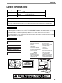
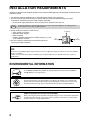

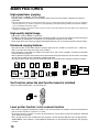

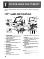
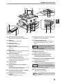
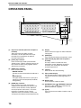

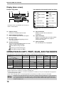


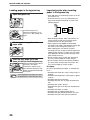


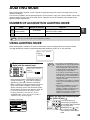
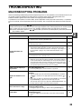


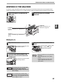
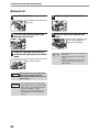

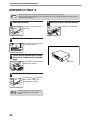
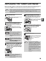

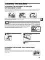
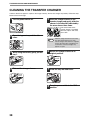
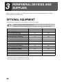


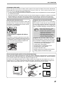
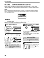
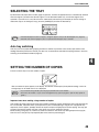

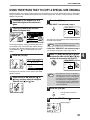
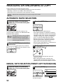

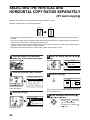

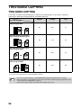


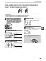


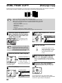
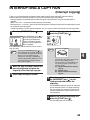
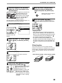
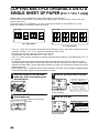
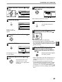
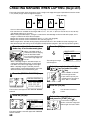

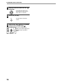

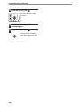
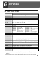
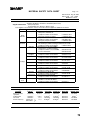
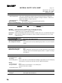
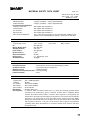
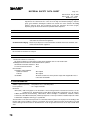
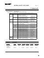


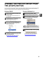
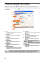

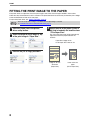
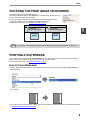


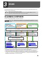

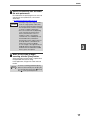

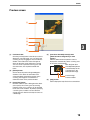
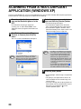
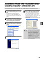
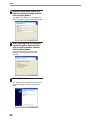
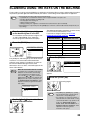

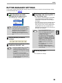

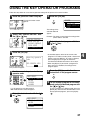
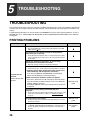
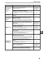
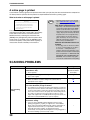
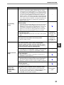
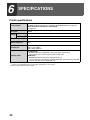
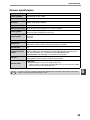


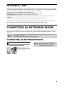

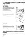


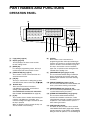
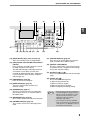
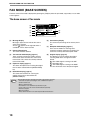
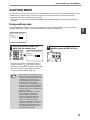
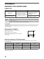


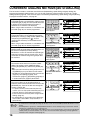


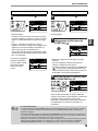
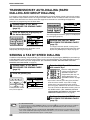
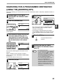
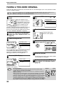
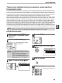
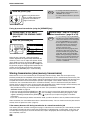
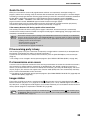

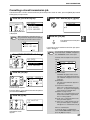
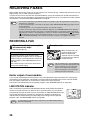

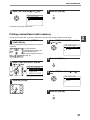
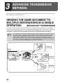
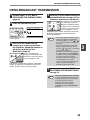
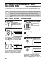
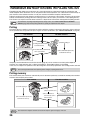
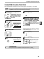

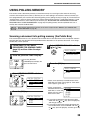
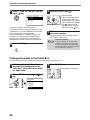


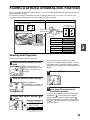
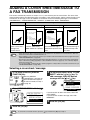

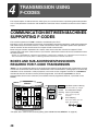
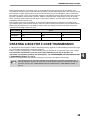


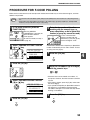

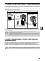

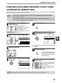
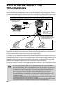


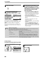
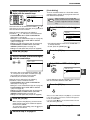


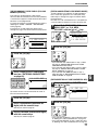

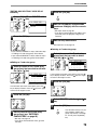
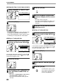
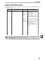
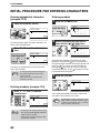
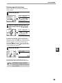


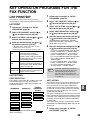
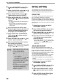

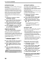
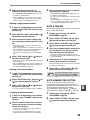
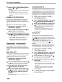

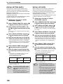
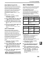

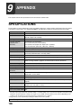


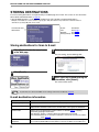
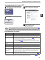
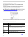

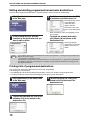

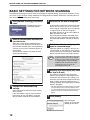

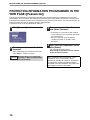

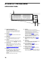

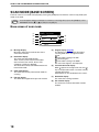
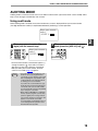
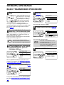

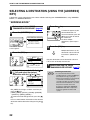

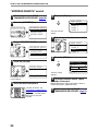
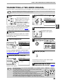
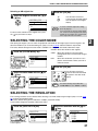

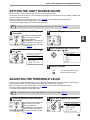
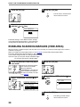


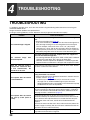
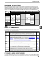
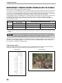
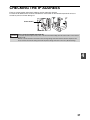


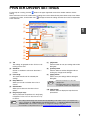
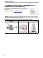
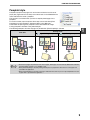

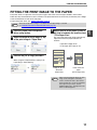

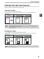
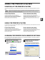


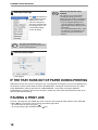

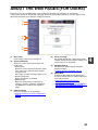

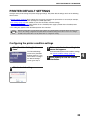
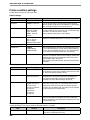
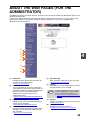


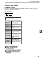

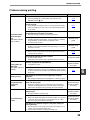

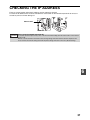

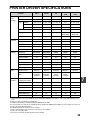

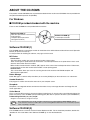


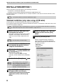
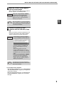
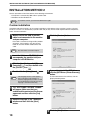

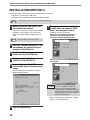
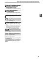
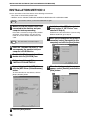
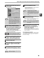
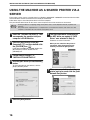
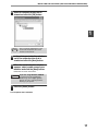

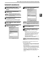


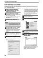
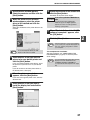


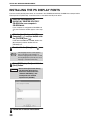


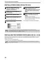
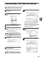
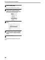


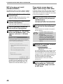

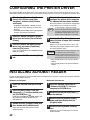
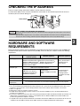


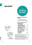


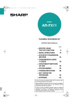
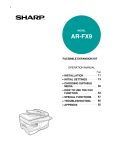
![3 Pulse la tecla [OK].](http://vs1.manualzilla.com/store/data/006242630_1-7a1c03e0b02b6620550bbf18f6c5e232-150x150.png)

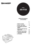


![2 Fare clic sul pulsante [start]](http://vs1.manualzilla.com/store/data/006118559_1-173242b46b2c9da737019e0375b2825a-150x150.png)