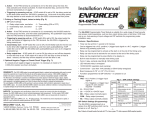
1
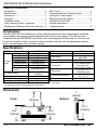
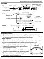
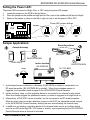
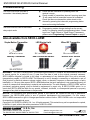
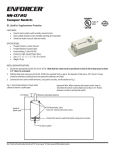
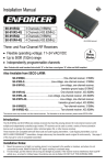
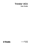
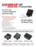
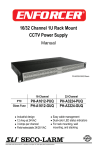
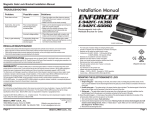
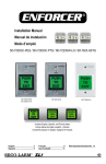
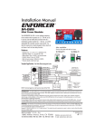
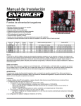
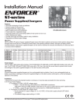
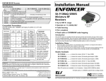
SK-910RC4Q
Central Receiver
Manual
4 Channels
4 Channel relay outputs
1 Auxiliary relay output (12VDC)
4 Relay output modes
4 Programmable alert tones
Up to 500’ (152m) range
Note: Model numbers that end with “Q” or that have a round green “Q” sticker signify RoHS-compliant products.
ENFORCER SK-910RC4Q Central Receiver
Table of Contents:
Introduction ..................................................... 2
Specifications ................................................. 2
Dimensions ..................................................... 2
Overview ......................................................... 3
Installation Notes ............................................ 3
Code Learning a New Transmitter .................. 4
Displaying or Clearing a Channel’s Memory .. 4
Alert Tones ..................................................... 4
Programming Each Channel Output ............... 5
Setting the Timed Output ................................ 6
Setting the Auxiliary Relay .............................. 6
Setting the Power LED ................................... 7
Sample Applications ....................................... 7
Troubleshooting .............................................. 8
Introduction:
The SK-910RC4Q Central Receiver is a four-channel receiver with four independently controlled
output modes and a unique volume-adjustable alert tone for each channel. This RF receiver is
compatible with all ENFORCER transmitters, both code hopping and fixed code. The receiver can
be used to remotely control a variety of home automation devices, such as garage door openers,
lights, motorized gates, lifts, and other devices.
Specifications:
Operating voltage
Standby
1 Relay active
2 Relays active
Current 3 Relays active
draw
4 Relays active
All relays active
All relays +
sound
DC power supply
Relay type
Channels 1~4 relay rating
Auxiliary relay rating
12VDC
15mA@12VDC
85mA@12VDC
140mA@12VDC
210mA@12VDC
260mA@12VDC
330mA@12VDC
RF frequency
# of RF channels
Alert sound
Number of alert tones
Connectors
450mA@12VDC
500mA@12VDC
(included)
Form C (NO/NC/COM)
10A@12VDC
3A max.1
1Included
power supply will not support loads larger than 500mA.
For larger loads, replace with appropriate DC power supply.
Dimensions
Operating temperature
Range
2Actual
range will vary greatly depending on the operating
environment.
Dimensions:
Front:
41/8”
(105mm)
2
315MHz
4
100 +/- 3dB@10cm
adjustable
4, programmable
14-Pin terminal block,
3 pins per relay,
2-pin auxiliary output
55/16”x 33/16”x1”
(135x83x26 mm)
-40°~167° F
(-40°~75° C)
Up to 500’ (152m)2
1”
(26mm)
4”
(100mm)
Bottom:
33/16”
(83mm)
55/16”
(135mm)
SECO-LARM U.S.A., Inc.
ENFORCER SK-910RC4Q Central Receiver
Overview:
Mode button
Top:
Power Input
(12VDC)
Programming buttons
To antenna
Timer switches
Front:
Antenna
Volume
adjustment knob
Speaker
Status LEDs
Bottom:
Auxiliary relay output (12VDC) Main relay outputs
Installation Notes:
1. Mount in a convenient location where alert tones and LED indicators will be audible/visible.
2. Do not install in a location surrounded by metal as RF signals may be blocked, decreasing range.
3. Do not install in a location exposed to weather, moisture or high humidity.
To open the housing:
1. Remove the antenna by unscrewing the antenna base counterclockwise.
2. Remove the bottom cover starting from point 1 shown in the diagram. Follow with points 2 and 3.
NOTE: Applying outward pressure on the clip points will help release the bottom cover.
3. Before attempting to release point 4, gently slide the bottom cover down and left to bring the
programming buttons out of their holes in the housing.
Clip Points
4. Disconnect the speaker plug from the PCB to avoid damage
while working with the cover off.
5. When replacing the bottom cover, ensure the speaker wires are
not caught between the speaker and the PCB. Check that buttons
and knobs are properly inserted in their openings in the housing.
NOTE: Buttons and knobs are connected directly to the PCB.
Be gentle to avoid damaging delicate electronics. Do not
force the cover on or off if resistance is felt.
SECO-LARM U.S.A., Inc.
3
ENFORCER SK-910RC4Q Central Receiver
Code Learning a New Transmitter:
Each receiver channel can learn the codes of up to 15 different transmitters. Transmitters are
learned on a first-in, first-out basis. (For example, if 15 transmitter codes have been learned, when
a new transmitter is learned the first of the 15 codes that were learned before will be deleted.)
1. To learn a new transmitter, first press and hold the programming button of the channel to be
programmed for 3 seconds or more. (Programming buttons are found on the top of the unit.)
Note: A pencil or other pointed object may be necessary to press the programming buttons.
2. The channel’s red LED will flash quickly to indicate it is in Learning Mode. DO NOT REPEAT
STEP 1 WHILE THE LED IS FLASHING OR CHANNEL MEMORY WILL BE CLEARED.
3. While the channel LED is flashing, press the button of the transmitter being learned one time.
The channel’s LED will flash once to indicate the transmitter code was successfully learned.
4. If no transmitter is learned within 15 seconds, the receiver will return to standby mode.
5. If the transmitter has been learned already, the channel LED will turn steady ON and the code
will not be learned a second time.
Displaying or Clearing a Channel’s Memory:
Display Channel Memory:
1. Press a channel’s programming button once.
2. The number of flashes is the same as the number of transmitters that channel has learned.
Clear Channel Memory:
1. Hold down the channel’s programming button for three seconds.
2. The channel’s red LED will start flashing.
3. After the LED has started flashing, hold down the programming button for three more seconds.
The LED will flash two more times, indicating that all codes learned by that channel have been
cleared.
Alert Tones:
Each channel has a specific alert tone. See the chart on the lower right.
1. Open the housing following the instructions under Installation Notes on page 3 of this manual.
2. Locate the Alert Tones DIP switch marked SW7. Switches marked 1 through 4 determine
whether each channel’s sound will play when the respective channel is triggered.
3. If the switch is in the ON position, the alert tone will play when the channel is triggered.
4. If the switch is in the OFF position, no alert tone will play when the channel is triggered.
5. Adjust the volume using the volume adjustment knob.
PCB
Volume
adjustment
knob
Alert Tone
DIP switch
(SW7)
4
Alert Tones
Channel 1
Doorbell
Channel 2
Bells
Home Sweet
Channel 3
Home
Channel 4
Alarm
SECO-LARM U.S.A., Inc.
ENFORCER SK-910RC4Q Central Receiver
Programming Each Channel Output:
1. Each channel output can be separately programmed for one of four different modes:
Timed Output: When the channel receives a signal, the relay will turn ON for 1~60 seconds,
depending on the output time set.
Note: The timer, once set, is the same length for all outputs programmed for Timed Output.
(See page 6 for timer programming.)
Toggle Output: When the channel receives a signal, the relay will turn ON and remain
activated until a second signal is received.
Latch Output: When the channel receives a signal, the relay will turn ON. Turn the relay OFF by
pressing that channel’s programming button on the Central Receiver unit.
Validity Output: When the channel receives a signal, the relay will turn ON for as long as a signal
is being received.
2. To enter programming mode, press the button marked Mode on the top of the unit. Each
channel’s red LED will flash a number of times to show the current output mode that it is in:
# of Flashes
1
2
Output Mode
Timed Output
Toggle Output
# of Flashes
3
4
Output Mode
Latch Output
Validity Output
3. To change modes, press the desired channel’s transmitter programming button. Each press
moves to the next mode in the sequence shown in the diagram below. After changing modes,
count the number of times the channel LED flashes to verify the channel is in the correct mode.
Toggle Output
4. When finished, press Mode again to end programming.
Example 1: If the present mode is Timed Output, and
the desired mode is Latch Output, press the
channel’s programming button 2 times.
Example 2: If the present mode is Validity Output and
the desired mode is Latch Output, press the
channel’s programming button 3 times.
(2 flashes)
Timed Output
(1 flash)
Latch Output
(3 flashes)
Validity Output
(4 flashes)
Programming Button Functions (Per Channel)
Learn mode
Clear memory
Reset Latch Output
Memory display
Press and hold the button for 3 seconds or more to enter Learn mode.
Press and hold the button for 3 seconds or more. When LED starts flashing, press
and hold again for 3 seconds to delete all learned codes. LED will flash twice.
If channel is set to Latch Output, press to turn relay off after it has been triggered.
Press momentarily. The Channel LED will flash a number of times corresponding to
the number of codes stored.
LED Indicator Functions (Per Channel)
Steady ON
Fast flash
One flash
Two flashes
Three flashes
Four flashes
0~15 flashes
Receiving signal from transmitter OR indicates code has already been learned
during code learning.
In either code learning OR memory display OR channel output programming mode.
A transmitter’s code was learned OR channel relay is in Timed output mode.
All learned codes were deleted OR channel relay is in Toggle output mode.
Channel relay is in Latch output mode.
Channel relay is in Validity output mode.
During normal operation, press the programming button to display the number of
codes stored. 1 flash = 1 code stored.
SECO-LARM U.S.A., Inc.
5
ENFORCER SK-910RC4Q Central Receiver
Setting the Timed Output:
When a channel is set to Timed Output, triggering the channel will activate the relay for a set
period of time. Factory default is 1 second.
1. The time can be set from 1~60 seconds using the Timer switches on the top of the receiver.
2. Set switches according to the following chart.
NOTE: The time set via the DIP switches applies to all channels programmed for Timed Output.
Sec.
1*
2
3
4
5
10
30
60
SW1
On
Off
Off
On
Off
On
Off
On
SW2
Off
On
Off
Off
On
On
Off
On
SW3
Off
Off
On
On
On
Off
Off
On
Top of unit
Timer switches
SW1 SW2 SW3
*Default setting
Setting the Auxiliary Relay:
Each channel may be individually set to activate a separately timed 12VDC output programmable
from 1 second to 10 minutes. The auxiliary relay provides up to 3A@12VDC*.
1. Connect the auxiliary device to the auxiliary relay. The two auxiliary relay terminals are the
left-most terminals on the terminal block as shown in the diagram below.
2. Select which channels will trigger the auxiliary relay using the Auxiliary Relay DIP switch
(SW8), located on the PCB as shown in the diagram below.
3. If the switch is in the ON position, triggering the
corresponding channel will activate the auxiliary relay.
*Note
Included power supply will not
4. If the switch is in the OFF position, triggering the
support loads larger than 500mA.
corresponding channel will not activate the auxiliary relay.
For larger loads, replace with
appropriate DC power supply.
Setting Auxiliary Relay Timer:
1. Output time can be adjusted from 1 second to 10 minutes
using the auxiliary relay output time potentiometer.
2. Turning the potentiometer clockwise will increase the output time.
3. Turning the potentiometer counterclockwise will decrease the output time.
Auxiliary relay time potentiometer
Use the DIP switch to select the
channel. Default is Channel 1 ON.
PCB
6
Terminal Block
Auxiliary relay terminals
SECO-LARM U.S.A., Inc.
ENFORCER SK-910RC4Q Central Receiver
Setting the Power LED:
The power LED can be set to Bright, Dim, or OFF using the power LED jumper.
1. Locate the jumper on the PCB as shown below.
2. Place the jumper on the middle and right pins for Dim, and on the middle and left pins for Bright.
3. Remove the jumper or place on the left or right pin only to set the power LED to OFF.
Power LED jumper settings
Jumper
PCB
Dim
Sample Applications:
Bright
Off
Recording station
Outside driveway
DR-116Q
SK-919TDWS-BU
E-960-D90Q
Indoor location
SK-910RC4Q
Lamp
SK-919TDWS-BU
SL-1301-BAQ
1. A photobeam sensor installed on a driveway (E-960-D90Q or similar) is connected to an
RF wired transmitter (SK-919TDWS-BU or similar). When the photobeam sensor is
triggered, the transmitter sends a signal to the SK-910RC4Q Central Receiver.
2. Inside, an alarm, lamp, or other signaling device is connected to the channel’s relay output.
When the intruder triggers the photobeam sensor, an alarm is triggered or the light turns on.
3. Alternatively, a DVR (DR-1 series or similar) can be connected to an RF wired transmitter.
When an event (such as motion detection) occurs on the DVR, the transmitter sends a signal
to the SK-910RC4Q Central Receiver, alerting the user and activating the channel relay.
4. In addition to connecting a signaling device to the channel relay output, an auxiliary device
such as an LED strobe light (SL-1301 series or similar), can be powered by the SK-910RC4Q
Central Receiver when a channel is activated.
SECO-LARM U.S.A., Inc.
7
ENFORCER SK-910RC4Q Central Receiver
Troubleshooting:
The SK-910RC4Q will not read a
transmitter it has already learned.
Check that the transmitter is operating within the
receiver’s range.
Check number of transmitters learned. Learning more than
15 will cause the first transmitter learned to be deleted.
Check that there are transmitter codes stored on the
channel by pressing that channel’s programming button
once and counting the flashes.
The SK-910RC4Q is not in the correct
relay output mode.
Programming modes change starting from the current
mode. For example, press the programming button 3 times
to go from Toggle Output to Timed Output. If necessary,
please review Programming Channel Output on page 5.
Also Available from SECO-LARM:
Single-Button Transmitter
LED Strobe Light
Wired RF Transmitter
SK-919TD1S-UP
SL-1301-BAQ Series
SK-919TDWS-BU
Desktop Transmitter
Dual Photobeam Sensor
Electric Door Strikes
SK-919TP2D-P
E-960-D90Q
SK-990AQ
WARRANTY This SECO-LARM product is warranted against defects in material and workmanship while used
in normal service for a period of one (1) year from the date of sale to the original consumer customer.
SECO-LARM’s obligation is limited to the repair or replacement of any defective part if the unit is returned,
transportation prepaid, to SECO-LARM. This Warranty is void if damage is caused by or attributed to acts of
God, physical or electrical misuse or abuse, neglect, repair, or alteration, improper or abnormal usage, or faulty
installation, or if for any other reason SECO-LARM determines that such equipment is not operating properly as
a result of causes other than defects in material and workmanship. The sole obligation of SECO-LARM, and the
purchaser’s exclusive remedy, shall be limited to replacement or repair only, at SECO-LARM’s option. In no
event shall SECO-LARM be liable for any special, collateral, incidental, or consequential personal or property
damages of any kind to the purchaser or anyone else.
NOTICE: The information and specifications printed in this manual are current at the time of publication.
However, the SECO-LARM policy is one of continual development and improvement. For this reason,
SECO-LARM reserves the right to change specifications without notice. SECO-LARM is also not responsible
for misprints or typographical errors.
Copyright © 2010 SECO-LARM U.S.A., Inc. All rights reserved. This material may not be reproduced or copied,
in whole or in part, without the written permission of SECO-LARM.
SECO-LARM® U.S.A., Inc.
16842 Millikan Avenue, Irvine, CA 92606
Tel: 800-662-0800 / 949-261-2999 Fax: 949-261-7326
8
Website: www.seco-larm.com
E-mail: [email protected]
PITSW1
MiSK-910RC4Q_1007.docx
Order Part# 762-508-1%
SECO-LARM U.S.A., Inc.