1
OWNER'S
MANUAL
247.799640
CRRFTSMRN®
9 HORSEPOWER
MULCHING AND BAGGING
CHIPPER-VACUUM
Caution:
Readand Follow
All SafetyRules
and Instructions
BeforeOperating
This Equipment
Assembly
Operation
Customer Responsibilities
Service and Adjustment
Repair Parts
SEARS, ROEBUCKAND CO., Hoffman Estates, IL 60179 U.S.A.
i
inted in U,S.A.
770-8894K
2/95
!MPORTANT
OPERATIONPRACTICES
THISSYMBOLPOINTSOUTIMPORTANT
SAFETYINSTRUCTIONS
WHICH,IF NOTFOLLOWED,
COULDENDANGER
THE PERSONAL
A
ATTEMPTING
TOOPERATE
YOURPOWER
CHIPPER-VACUUM.
COMPLY
WITHTHESE
INSTRUCTIONS
MAYRESULTIN
AFETYAND/ORPROPERTY
OFYOURSELF
AND OTHERS.RFAILURE
EADANDTO
FOLLOW
ALL
INSTRUCTIONS
IN THIS MANUALBEFORE
_
PERSONAL
INJURY.WHENYOUSEETHISSYMBOL-- _
&
_hl.
DANGER:
REEDITSWAFINING.
Your chipper-vacuum was built to be operated according to the rules for safe operation in
this manua. As with any type of power equipment carelessness or error on the part of the
operator can result in serious injury. This unit is capable of amputating fingers and hands
and throwing objects. Failure to observe the following safety instructions couso result in
serious injury or death.
GENERAL
OPERATION
• Readthis owner'sguide carefullyin its entiretybeforeattempting to assemblethis machine. Read,understand,and follow all
instructionson the machineand in the manual(s)before operation. Becompletelyfamiliarwith thecontrolsandthe proper use
of the machinebeforeoperatingit. Keepthis manualin a safe
piecefor future and regular referenceand for ordering replacement parts.
• Your chipper-vacuum is a powerful tool, not a plaything.
Therefore,exerciseextremecaution at all times. Your unit has
beendesignedto performtwo jobs; to chip andvacuumvegetation found in a normalyard. Donot useit for any otherpurpose.
• Neverallow childrenunder 16 to operatethe unit. Children16
yearsand older shouldonly operateunder close parentalsupervision. Only responsibleindividuatswho are familiar with these
rulesof safeoperationshouldbe allowedto useyour unit.
• Keepthe areaof operationclearof all persons,particularlysmall
childrenand pets. Stop the enginewhen they are in the vicinity
of the unit.
• Whenfeedingmaterialinto this equipment,beextremelycareful
that piecesof metal,rocks,bottles, cansor otherforeign objects
are not included. Personal injury or damageto the machine
could result.
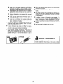
• Alwayswear safetyglassesor safetygoggles, during operation
and while performing an adjustmentor repair, to protect eyes
from foreignobjectsthat maybe thrown from the machine.
• Wearsturdy, rough-soledwork shoes and close fitting slacks
and shirt. Shirt and slacks that cover the arms and legs and
steel-toedshoes are recommended. Do not wear loosefitting
clothes or jewelry and secure hair so it aboveshoulderlength.
They can be caught in moving parts. Never operatea unit in
barefeet, sandalsor sneakers.Weargloves whenfeedingmaterial in the chipperchute.
• Do not operatethe unit while underthe influenceof alcoholor
drugs.
_lb
• Do notover-reach.Keepproperfooting and balanceat all times.
• Neverplaceyour handsor anypartof your bodyor clothingnear
or under rotating parts. Keepclear of the dischargeopening at
all times Neverinsert your handsor anypart of your body or
clothing into the nozzle,chipperchute or dischargeopeningas
the rotatingimpetlercan causeseriousinjury.
• If it is necessaryfor any reasonto unclogthe feed intakeor dischargeopeningsor to inspector repair any part of the machine
where a moving part can come in contact with your body or
clothing, stopthe machine+allowit to cool, disconnectthe spark
plug wire from the spark plug and move it awayfrom the spark _1
plug beforeattemptingto unclog,inspector repair.
• Never operate unit without vacuum bag and discharge chute
properly affixed to unit, Largezippered end of bag must be
closedto preventobjectsfrom beingblownout.
• Never operate unit without either the inlet nozzle or optional
hoseattachmentproperlyaffixed to unit. These devicesshield
the operatorfrom accidentalcontact with the rotating impeller.
Neverattempt to convertthe unit from nozzleto hose mode or
vice versawith the enginerunning.
• Neverattempt to removeor emptyvacuum bag when engine is
running. Shutthe engineoff and wait for the impellerto cometo
a completestop beforeremovingthe bag. The impetlercontinues to rotate for a few seconds after the engine is shut off.
Neverplaceany part of the body in the impellerarea until you
are surethe impellerhas stoppedrotating.
• Keepall guardsand safety devicesin placeand operatingproperly.
• Do not allow an accumulationof processedmaterialto build up
in the dischargearea as this will preventproper dischargeand
canresuttin kick-backfrom the chipperchute.
• Keepyour face and body backfrom chipperchuteto avoid accidentalbouncebackof anymaterial.
• If the cutting mechanism strikes a foreign object or if your
machine should start making an unusual noise or vibration,
immediatelystop the engine,disconnectthe spark plug wire and
movethe wire awayfrom the sparkplug. Allow the machineto
stop andtakethe following steps.
• Inspectfor damage
• Repairor replaceanydamagedparts.
• Checkfor any loose parts and tighten to assure continued
safeoperation.
• Muffter and engine becomehot and can cause a burn. Do not
touch.
• Donot altowleavesor other debristo build up on engine'smuffler. Thedebriscould igniteand causea fire.
• Donot operateengineff air cleaneror coverover carburetorairintake is removed, except for adjustment. Removal of such
partscould createa fire hazard.
11,CHILDREN
Tragicaccidentscan occur if the operatoris not alert to the presenceof small children. Childrenare often attractedto the chipping
and vacuumingactivity. Neverassumethat children will remain
whereyou last sawthem.
• Keepchildrenout of the work areaand underthe watchful eyeof
a responsibleadultotherthanthe operator.
• Bealertand turn the unit off if e child entersthe area.
• Neverallow childrenunderthe age of 16 to operatethe chipperVacuum.
111.SERVICE
• Use extreme care in handling gasoline and other fuels. They are
extremely flammable and the vapors are explosive.
• Store fuel and oil in approved containers, away from heat
and open flame, and out of the reach of children.
•
Check and add fuel beforestarting the engine. Never
remove gas cap or add fuel while the engineis running.
Allowengineto cool at leasttwo minutesbeforerefueling.
•
Replacegasoline cap securely and wipe off any spilled
gasolinebeforestartingthe engineas it maycausea fire or
explosion.
• Extinguish
all cigarettes,cigars,pipesand othersourcesof
ignition.
• Neverrefuel unit indoors becauseflammablevapors will
accumulatein the area.
• Never store the machine or fuel container inside where
there is an open flame or spark such as a gas not water
heater,clothesdryer or furnace.
• Neverrun your machinein an enclosedareaas theexhaustfrom
the engine contains carbon monoxide, which is a odorless.
tastelessand deadlypoisonousgas.
• To reducefire hazard,keep engine aria muffler free of leaves.
grass,and other debris build-up, Cleanup fuel and oi! spillage.
Allowunit to coolat least5 minutesbeforestoring.
• Keepall nuts. bolts,and screws tight to be surethe equipmentis
in safe workingcondition.
• Nevertamper with safety devices. Checktheir proper operation
regularly.
• After striking a foreign object,immediatelystop the engine,disconnectthe spark plug wire from the spark plug,and thoroughly
respectthe unit for anydamage. Repairdamagebeforestarting
ano operatingunit.
• Do not alter or romperwith the engine'sgovernorsetting. The
governor controlsthe maximum safe operating speed of the
engine. Over-speedingthe engine is dangerousand will cause
damageto theengineandto othermoving partsof the machine.
• Checkthe vacuum Dogfrequentlyfor wear. Replaceif worn or
damaged.
• Keepvacuumbag freeof debriswhen notJnuse.
• Before cleaning, repairing, or inspecting, make certain the
=rop!!letand all moving parts flare stopped. Disconnect the
spark plug wire and keepwire away from spark plugto prevent
accidentalstarting. Do not useflammablesolutionsto cleanair
filter.
SAF_
Restrict the use of this power machineto persons who read,
understand
_
WARNING
and follow the
-- warmngs
YOURRESPONSmluTY
and instructionsin this
manualand on the machine.
CONGRATULATIONS
on your purchase of a Sears
Craftsman
Chipper-Vacuum.
It has been designed,
engineered and manufactured to give you the best possible
dependability and performance.
Should you experience any problem you cannot easily remedy, please contact your nearest Sears Service Center/
Department in the United States, We have competent, welltrained technicians and the proper tools to service or repair
this unit.
Please read and retain this manual. The instructions will
PRODUCT
SPECIFICATIONS
Horsepower:
9.0
Engine Oil Capacity:
API Classification
SF, SG or SH
Fuel Capacity:
enable you to assemble and maintain your chipper-vacuum
properly. Always observe the "SAFETY RULES."
Spark
SAE 30
(26 Ounces)
Approximately
Plug (Gap
1 Gallon
(Unleaded)
.030 in.):
Champion
J-8C (or
MODEL
NUMBER
Equivalent)
247.799640
Tire Pressure:
SERIAL
NUMBER
DATE OF
PURCHASE
MAINTENANCE
THE MODEL AND SERIAL NUMBERS WILL BE FOUND
ON A LABEL ATTACHED
TO THE FRAME OF THE
CHIPPER-VACUUM.
A Sears
product.
YOU SHOULD RECORD BOTH SERIAL NUMBER AND
DATE OF PURCHASE AND KEEP IN A SAFE PLACE
FOR FUTURE REFERENCE.
CUSTOMER
•
•
•
24 p.s.i.
sibilities"
Manual.
and
"Storage"
sections
caring
In the State of California
the above is required by law
(Section 4442 of the California Public Resources Code).
Other states may have similar laws. Federal laws apply on
federal lands. A spark arrester for the muffler is available
through your nearest Sears Authorized Service Center (See
the REPAIR PARTS section of this manual.)
for
Respon-
of this
Maintenance
Agreement
is available
on this
Contact your nearest Sears store for details,
WARNING: This unit is equipped with an internal combustion engine and should not be used on or near any unimproved forest-covered, brush-covered or grass-covered land
unless the engine's exhaust system is equipped with a
spark arrester meeting applicable local or state laws (if any).
If a spark arrester is used, it should be maintained in effective working order by the operator.
RESPONSIBILITIES
Read and observe the safety rules.
Follow a regular schedule
in maintaining,
and using your chipper-vacuum.
Follow the instructions
under "Customer
AGREEMENT
Owner's
WARRANTY
FULL ONE YEAR WARRANTY ON CRAFTSMAN GAS CHIPPER-VACUUM
For one year from
tuned up according
free of charge,
the date of purchase,
when this Craftsman
chipper-vacuum
is maintained,
]ubricated,
and
to the operating
and maintenance
instructions
in the operator's
manual, Sears will repair,
any defect
in material
or workmanship.
This warranty
excludes the chipper blades, flails, air cleaners,
expendable
parts and become worn during normal use.
If this chipper-shredder
is used for commercial
or rental
spark
purposes,
plugs,
catcher
this warranty
bags
applies
and tires, which
for only
30 days
are
from
the date of purchase.
WARRANTY
SERVICE
IS AVAILABLE
UNITED
STATES.
THIS WARRANTY
STATES.
This warranty
gives you specific
SEARS
legal
ROEBUCK
BY CONTACTING
THE NEAREST
SEARS SERVICE
CENTER
APPLIES
ONLY WHILE THIS PRODUCT
IS IN USE IN THE
rights,
AND
and you may also have other rights
CO.,
DEPT.
817WA,
HOFFMAN
IN THE
UNITED
which vary from state to state.
ESTATES,
IL 60179
i
TABLE OF CONTENTS
SAFETY RULES .....................................................
2, 3
PRODUCT SPECIFICATIONS ................................... 4
MAINTENANCE AGREEMENT .................................. 4
CUSTOMER RESPONSIBILITIES
................. 4, 12. 13
WARRANTY ...............................................................
4
INDEX .........................................................................
,5
ACCESSORIES ..........................................................
5
ASSEMBLY .............................................................
6-8
ill
OPERATION .........................................................
8-11
CUSTOMER RESPONSIBILITt ES ..................... 12, 13
STO RAG E ................................................................
14
SERVICE AND ADJUSTMENT ........................... 14-17
TROUBLE SHOOTING .............................................
18
PARTS ORDERI N G/SERVICE ................................. 18
REPAIR PARTS--CHIPPER-VACUUM
.............. 19-25
REPAIR PARTS--ENGINE
................................. 26-29
l
INDEX
=
A
................................................................
Accessodes
5
Adjustments:
Carburetor .............................................................
17
Clutch Cable ...........................................................
7
Engine Speed .......................................................
17
Shift Rod ...............................................................
16
Assembly Instructions ..............................................
6-8
C
Catcher Bag ............................................................
7, 8
Controls ......................................................................
9
Customer Responsibilities .............................. 4, 12, 13
E
Engine:
Lubrication ............................................................
12
Maintenance ...................................................
12. 13
Starting .................................................................
11
Stopping ............................................................
9.11
Storage .................................................................
14
F
Fuel ...........................................................................
10
L
Lubrication ................................................................
12
M
Maintenance:
Agreement .............................................................
4
Schedule ...............................................................
12
Engine .............................................................
12, 13
Chippet'-Vacuum ..................................................
12
O
Oil .............................................................................
10
Operating Tips ......................................................
9, 10
R
Repair/Replacement
Parts .................................. 19-29
Responsibilities, Customer ............................ 4, 12, 13
S
Safety Rules ...........................................................
Sharpening ...............................................................
Spark Plug ................................................................
Specifications ..............................................................
Storage .....................................................................
T
Table of Contents .......................................................
Trouble Shooting ......................................................
U
2, 3
15
13
4
14
5
18
Unclogging ..........................................................
14, !5
Unpacking ...................................................................
6
W
Warranty ....................................................................
4
i=lu=
ACCESSORIES
These accessories were available when the chipper-vacuum
was purchased. They are also available at most
Sears retail outlets catalog and service centers. Most Sears stores can order repair parts for you, when you
provide the model number of your chipper-vacuum.
ENGINE
Spark
Plug
w
Air
Filter
Muffler
Engine[
Oil I
CHIPPER-VACUUM
Gas Can
Stabilizer
Hose
Kit
Vacuum
ASSEMBLY
INSTRUCTIONS
iiii
i
Bag
Hub
IMPORTANT: This unit is shipped WITHOUT GASOLINE or OIL in the engine. After assembly, see operation section of this manual for proper fuel and engine
oil recommendations.
Front Wheels
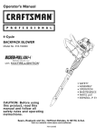
NOTE: To determine right and left hand sides of your
chipper-vacuum,
stand behind and face the unit
(Refer to figure 7).
Your chipper-vacuum
has been completely assembled at the factory except for the front wheels, hub
caps, nozzle, chipper chute, support bracket and bag.
A pair of safety glasses and bottle of oil are also
included in the carton.
TOREMOVECHIPPER-VACUUM
FROMCARTON
Cut the corner of the carton. Remove all packing
inserts and loose parts. Push down on handle to lift
front of chipper-vacuum,
and roll chipper-vacuum out
of the carton. Make certain all parts and literature
have been removed before the carton is discarded.
FIGURE 1.
TOOLS REQUIRED FOR ASSEMBLY
(1)
(2)
(1)
(1)
Wheel Bracket
3/4" Open End Wrench
1/2" or Adjustable Wrenches
9/16" Wrench
Funnel
LOOSE PARTS IN CARTON (SeeFigure1)
Wave
Washer
Shoulder
Bolt
Rex
Lock
Cupped
Washer
(2) Front Wheels
(2) Hub Caps-I
(1) Nozzle
(1) Chipper Chute
(1) Support Bracket
tNot Shown
(1)
(1)
(1)
(1)
(1)
Bag
Shift Knob1Tamper Plug-iSafety Glasses-I"
Bottle of Oil
HOWTO SET-UPYOUR CHIPPER-VACUUM
Cupped
Hub
Side
FIGURE 2.
Wing Nuts
Nozzle
FIGURE 3.
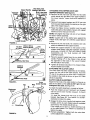
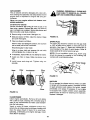
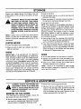
ATTACHING THE FRONT WHEELS
• Tilt unit backward so that it rests on the handle
(place a piece of the carton under handle to avoid
scratches).
Remove the cardboard
packing
material around the wheel brackets.
• Remove the hex lock nuts and shoulder bolts from
the front of the wheel brackets. See figure 2.
• Place wave washer
on shoulder
bolt. Insert
shoulder bolt through wheel, with the head of the
shoulder bolt through the flat side of the wheel.
• Assemble
wheel to outside of wheei bracket.
Secure with cupped washer
(cupped side of
washer goes against the bracket) and hex lock nut.
Tighten.
• Align the four tabs on the hub caps with the four
holes in the wheel. Press in each tab until it locks in
place. The hub cap edges must be flush with the
wheel rim when installed properly.
ATTACHING THE NOZZLE (See figure 3)
• Remove the three plastic wing nuts from the front
of the chipper-vacuum. Place the nozzle in position
over the three weld studs. Secure with the wing
nuts just removed.
NOTE: The metal tab in the nozzle must depress the
safety switch on the front of the chipper-vacuum
or
the engine will not start.
• Set unit in upright position.
He)( Bolts, Flat
its
HexNuts
Upper Handle
i
_Chiploer
Chute
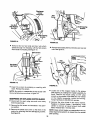
ATTACHING
THE CHIPPER CHUTE AND
SUPPORT BRACKET (See figure 4)
• Remove the two hex !ock nuts from the hex bolts
which secure the right side of the upper handle to
the lower handle, Leave bolts and washers in
•
jpporl
racket
•
place.
Remove three cupped washers and 5/16" hex nuts
from the weld studs beside the opening on the right
side of the chipper-vacuum,
Place the chipper chute in position over the weld
studs (slot goes at the bottom). Secure with cupped
washers and hex nuts just removed.
NOTE: Only tighten the three nuts one or two threads
for ease of further assembly.
Nuts
NOTE: Cupped side of the washer goes against the
chipper chute. See figure 2 to identify cupped side of
washer,
t/
FIGU RE 4.
"Z" End
of Cable
• Remove the two hex bolts, flat washers and nuts
which are attached to the support bracket.
Hole in Drive
Clutch Handle
• Attach the support bracket to the bottom of the
chipper chute loosely using the hardware removed
previously.
HEADS OF THE HEX BOLTS AND
WASHERS
GO TO THE INSIDE
OF THE
CHIPPER CHUTE.
Drive
Clutch
Handle
O
•
Nuts
• Tighten all hardware securely on the chipper chute,
support bracket and handle.
ATTACHING THE CLUTCH CABLE
The clutch cable has been assembled at the factory.
Loosen the hex nuts at the cable bracket. Hook the
"Z" end o_=the cable into the drive clutch handle from
the outside to the inside as shown in figure 5A. Pliers
will aid in assembly.
CLUTCH CABLE ADJUSTMENT
Cable is
Straight
Nuts
FIGURE 5.
Rib
Bag
Adjust the hex nuts at the cable bracket so there is no
slack in the cable, but the cable is NOT tight. Do not
overtighten the cable. See figure 5B.
Drive
Clutch Handle
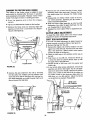
To check the clutch adjustment, oroceed as follows.
• Push tl_e chipper-vacuum
backward and forward
with the drive clutch handle released. It should
move freely.
If it does not, loosen both hex nuts at the cable
bracket. See figure 5B. Turn bottom nut counterclockwise to loosen the cable.
Discharge
Chute
/
..J
Place the support bracket over the [wo bolts in the
handle. Pushing UP on the chipper chute will aid
the alignment of the holes in the support bracket
with the bolts in the handle.
•
Drawstring
•
FIGURE 6.
7
Engage the drive clutch handle (hold against upper
handle), and try to push chipper-vacuum backward
and forward. The wheels should lock up.
If the wheels do not lock up, loosen both hex nuts
at the (:able bracket, Turn bottom nut clockwise to
tighten the cable.
Recheck adjustment, Tighten both hex nuts when
correct adjustment is reached.
Stra
aps on
Straps on
Baa
Shift Knob_
ATTACHING
THE BAG
•
Place bag inside of handle assembly.
Slip the
opening on the bag over the discharge chute, making certain it is over the rib on the discharge chute.
See figure 6.
•
Place the four straps on the top of the bag over
upper handle, hooking them on studs. See figure 7.
NOTE: Be sure the bag goes under the drive clutch
handle.
Upper Handle
/
I
• Squeeze the clamp on the drawstring,
drawstring tight. Release the clamp.
FIGURE 7.
INSTALLING
and puff the
THE SHIFT KNOB
Remove the cardboard protecting the threads. Thread
the shift knob onto the end of the shift lever.
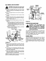
TAMPER PLUG
The handle on the tamper plug must be in the vertical
position as shown in figure 8. To determine which
side of the tamper plug is up, match the angle of the
tamper plug to the angle of the chipper chute.
insert the tamper plug into the chipper chute. Tamper
plug should remain in the chipper chute whenever the
chipper chute is not in use.
FIGURE 8.
i
OPERATION
==1
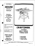
KNOW YOUR CHIPPER-VACUUM
READ THIS OWNER'S MANUAL AND SAFETY RULES BEFORE OPERATING YOUR CHIPPER-VACUUM.
Compare the illustrations with your chipper-vacuum to familiarize yourself with the location of various controls and
adjustments. Save this manual for future reference.
Spark Plug
Oil
Boot
Drive Clutch
Dipstick
Shift
Handle
Lever
Choke
Chipper
Chute
Starter
Han<
Fast
Nozzle
FIGURE 9.
MEETS ANSI SAFETY STANDARDS
Sears chipper-vacuums
conform to the safety standards of the American National Standards InsUtute.
OPERATINGCONTROLS (See
the wheel drive. Release the drive clutch handle to
stop the forward ddve.
figure 9)
SHIFT LEVER--The
shift lever determines ground
speed. It may be placed in one of eight positions.
Forward--one
of six speeds. Position number one (1)
Esthe slowest. Position number six (6) is the fastest.
Reverse--two reverse (R) speeds. "R" (all the way to
the right) is the faster of the two.
DRIVE CLUTCH HANDLE (BAIL)--Squeezing
the
drive clutch handle against the upper handle engages
CHOKE LEVER--Used
to enrich the fuel mixture in
the carburetor when starting a cold engine.
STARTER
engine.
HANDLE--Used
to manuatty
THROTTLE CONTROL--Controls
stops the engine.
BEFORE USING YOUR CHIPPER-VACUUM,
AGAIN REFER TO THE "SAFETY
PAGE 2 OF THIS MANUAL. ALWAYS BE CAREFUL.
start the
engine speed and
RULES"
AS SHOWN
ON
The operation of any chipDer-vacuurr can result in foreign objects being thrown into the eyes, which
can result in severe eye damage. Always wear the safety glasses providedwith the chipper-vacuum or
eye shields before chi_pJng, or while _erforming any adjustments er repairs We recommend Wide
Vision Safety Mask for over spectacles or standard glasses available at Sears Retail er Catalog Stores.
TO STOP ENGINE
The best height for the nozzle will vary according to
the conditions. Adjust the height of the nozzle to find
the setting which gives the best performance for the
operating conditions. In general, raise the nozzle to
vacuum a thick layer of leaves; lower the nozzle for
smooth surfaces.
• Move throttle control lever to STOP position. See
figure 9.
• Disconnect spark plug wire and move away from
spark plug to prevent accidental
starting while
equipment is unattended.
HOW TO USE YOUR CHIPPER-VACUUM
_IL
Height
Adjustment
Knob
EQUIPPED WITH A SAFETY SWITCH ON
WARNING:
CHIPPER-VACUUM
THE FRONT YOUR
OF THE
HOUSING, NOZZLEiS
OR HOSE ATTACHMENT
MUST BE IN
PLACE
ON THE CHIPPER-VACUUM
BEFORE THE ENGINE CAN BE STARTED.
i!
TO ENGAGE DRIVE
IMPORTANT:
Always release the drive clutch
handle before moving the shift lever.
• With the engine running near top speed, move shift
lever into one of the six FORWARD _ositions or
two REVERSE positions. Select a speed appropriate for the conditions that exist. Use the slower
speeas until you ere familiar with the operation of
the chipper-vacuum.
e To engage the wheel drive, hold the drive clutch
handle against
the chipper-vacuum
handle.
Releasing the drive clutch handle stops the wheels
from driving. Retease the drive clutch handle to
slow down when negotiating an obstacle making a
turn or stopping. Engage slowly to prevent front
wheels from lifting up.
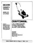
NOZZLE HEIGHT ADJUSTMENT
The height adjustment knob is located on the right
hand side of the chipper-vacuum. See figure 10. Tunthe knob clockwise to raise the nozzle. Turn the knob
counterclockwise to lower. (Be careful not to turf
knob too far--rod could come out of ferrule.)
FIGURE 10.
USING THE CHIPPER CHUTE
Do not a_empt to chip any materiel other than vegetation found in a normal yard (i.e., branches, leaves,
twigs, etc.). Matedal such as stalks or heavy branches
up to 3" in diameter
may be fed into the chipper
chute. See figure 11
WARNING:
MATERIAL
UP TO A MAXIMUM OF 3" IN DIAMETER MAY BE FED
INTO THE CHIPPER
CHUTE. DO NOT
ATTEMPT
TO CHIP ANY MATERIAL
LARGER
THAN
3" IN DIAMETER,
PERSONAL
INJURY OR DAMAGE
TO
THE MACHINE COULD RESULT,
9
GASAND OIL FILL-UP
If necessary, use the tamper plug provided to push
material into the chipper chute. See figure 8. NEVER
PLACE HANDS INSIDE CHIPPER CHUTE. PIace
OIL
Only use high quality detergent oil rated with API
service classification SF, SG or SH. Select the oil's
viscosity grade according to your expected operating
temperature.
tamper plug inside chipper chute when not in use to
deaden the sound.
Colder
<
32°F
5W30
_- Warmer
SAE 30
NOTE: Although multi-viscosity
oils (5W30, 10W30,
etc.) improve starting in cold weather, these multiviscosity oils will result in increased oil consumption
when used above 32°F. Check your oil level more
frequently
to avoid possible engine damage from
running low on oil.
• Use engine oil provided. Remove oil fill dipstick.
See figure 13. With chipper-vacuum
level, use a
funnel to fill engine with oil to FULL mark on dipstick.
Capacity is approximately 26 ounces. Be careful not
to overfill. Oil bottle provided contains 27 oz. of oil.
Tilt chipper-vacuum toward the left (from behind the
hopper), then re-level. Check oil level. Refill to FULL
mark on dipstick if necessary. Replace dipstick and
tighten.
FIGURE 11.
IMPORTANT: There is a flail screen located inside
the housing in the discharge area. If the flail screen
becomes clogged, remove and clean as instructed in
the Service and Adjustment section on page 14.
For best performance,
it is important to keep the
chipper blades sharp. If the composition
of the
material being discharged changes (becomes stringy,
etc.) or if the rate at which the material is discharged
slows down considerably, it is likely that the chipper
blades are dutl and need to be sharpened
or
replaced. Refer to Service and Adjustments sections.
Oil
Fill
Dipstick
TO EMPTY BAG
Open the large zipper on the bag to empty the bag.
See figure 12. Be certain the zipper is closed when
operating the unit.
Oil
Drain
FIGURE 13.
GAS
• Remove fuel cap and fill fuel tank with approximately 1 gallon of clean, fresh, lead-free grade
automotive gasoline. DO NOT use Ethyl or high
octane gasoline. Be certain container is clean and
free from rust or foreign particles. Never use gasoline that may be stale from tong periods of storage
in the container. Replace fuel cap.
_L
FIGURE 12.
10
1/'2 INCH OF TOP OF FUEL TANK TO
WARNING:
DO NOTAND
FILLTO
CLOSER
PREVENT SPILLS
ALLOW THAN
FOR
FUEL EXPANSION.
IF GASOLINE
IS
ACCIDENTLY SPILLED, MOVE CHIPPERVACUUM AWAY FROM AREA OF SPILL.
AVOID CREATING
ANY SOURCE
OF
IGNITION
UNTIL GASOLINE
VAPORS
HAVE DISAPPEARED.
Check the fuel level periodically to avoid running out
of gasoline while operating the chipper-vacuum. If the
unit runs out of gas as it is chipping, it may be necessary to unclog the unit before it can be restarted.
Refer to "Removing the Flail Screen" in SERVICE
AND ADJUSTMENT section.
NOTE: A noise will be heard when finding the start of
the compression
cycle. This noise is caused by the
flails and fingers which are part of the shredding mechanism failing into place, and should be expected. In
addition, the flails and fingers will be noisy after the
engine is started, until the impeller reaches full speed.
•
WARNING: EXPERIENCE INDICATES THAT ALCOHOL BLENDED FUELS (CALLED GASOHOL OR
USING ETHANOL OR METHANOL) CAN ATTRACT
MOISTURE WHICH LEADS TO SEPARATION AND
FORMATION
OF ACIDS DURING
STORAGE.
ACIDIC GAS CAN DAMAGE THE FUEL SYSTEM
OF AN ENGINE WHILE IN STORAGE. TO AVOID
ENGINE
PROBLEMS,
THE
FUEL
SYSTEM
SHOULD BE EMPTIED OR TREATED WITH FUEL
STABILIZER
BEFORE STORAGE FOR 30 DAYS
OR LONGER. USE FRESH FUEL NEXT SEASON.
SEE "STORAGE"
SECTION
FOR ADDITIONAL
INFORMATION.
Pull rope with a rapid, continuous, full arm stroke.
Keep a firm grip on start handle. Let rope rewind
slowly. Do not let starter handle snap back against
starter.
• Repeat preceding two instructions
until engine
fires. When engine starts, move choke lever on
engine hatfway between CHOKE and OFF.
NOTE: ff engine does not fire after three attempts,
move choke lever halfway between CHOKE and OFF
position and try again.
•
NEVER USE ENGINE OR CARBURETOR CLEANER PRODUCTS IN THE FUEL TANK OR PERMANENT DAMAGE MAY OCCUR,
Move throttle control to IDLE position for a few minuzes warm-up. Move choke lever to OFF position
as engine warms up.
NOTE: In order to idle smoothly, a new engine may
require 3 to 5 minutes running above slow idle speed.
Idle speed has been adjusted to be correct after this
break-in period.
TO STARTENGINE
IMPORTANT:
IF UNIT SHOWS ANY SIGN OF
MOTION WITH THE CLUTCH
HANDLE DISENGAGED,
SHUT ENGINE
OFF IMMEDIATELY.
READJUST
AS INSTRUCTED
IN THE "FINAL
ADJUSTMENTS"
SECTION OF THE ASSEMBLY
INSTRUCTIONS.
&
Full Choke
Position
WARNING:
BE SURE NO ONE OTHER
THAN THE OPERATOR
IS STANDING
NEAR THE CHIPPER-VACUUM
WHILE
STARTING
OR OPERATING.
DO NOT
OPERATE
THIS
CHIPPER-VACUUM
UNLESS
THE NOZZLE,
DISCHARGE
CHUTE AND BAG HAVE BEEN PROPERLY INSTALLED.
Lever
• Attach spark plug wire and rubber boot to spark
plug if necessary. See figure 9.
•
Off
Position
FIGURE 14,
Place the throttle control lever in FAST position.
• Move choke lever to CHOKE position (See figure
14).
TO STOP ENGINE
• Place one foot on the left rear wheel to 0revent the
unit from skidding while starting.
• Grasp starter handle and pull rope out slowly until
engine reaches start of compression cycle (rope
will pull slightly harder at this point). Let the rope
rewind slowly.
11
•
Move throttle control lever to STOP position.
•
Disconnect spark plug wire and move away from
spark plug to prevent accidental starting while
equipment is unattended.
CUSTOMER
,,==,=
o=,==
==.
0==
===v,c=
RESPONSIBILITIES
.
* O"
o..==
F-
_
Oil Pivot Points
"J
a
O
_:
Clean Chipper-Vacuum
_/
Check Engine Oil
_
_/
Change Engine Oil
_/
_J
UJ
z
ug
Service Air Cleaner
_/
Clean Engine Cylinder
q
_/
Spark Plug
_/
._I
Muffler
_/
_/ CHECK
Colder
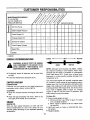
GENERAL RECOMMENDATIONS
•
Periodically check all fasteners
are tight.
•
Follow the Maintenance
_- Warmer
SAE 30
NOTE: Although multi-viscosity
oils (SE30, 10W30,
etc.) improve starting in cold weather, these multiviscosity oils will result in increased oil consumption
when used above 32°F. Check your oil level more
frequently to avoid possible engine damage from
running low on oil.
and be sure they
Schedule above.
Your four-cycle engine will normally consume some
oil--therefore, check engine oil level regularly approximately every five hours of operation and before each
usage. Stop engine and wait several minutes before
checking oil level. With engine level, the oil must be to
FULL mark on dipstick (refer to figure 10). Change
engine oil after the first five hours of operation, and
every twenty-five hours thereafter.
CHIPPER-VACUUM
LUBRICATION
Lubricate the pivot points on the height adjustment
mechanism once a season using a light oil.
CLEANING
• Clean the chipper-vacuum
32°F
5W30
AND DISCONNECT
THE SPARK PLUG
WARNING:
ALWAYSPERFORMING
STOP THE ENGINE
WIRE
BEFORE
ANY
MAINTENANCE OR ADJUSTMENTS.
_b
_
thoroughly after each
use.
To Drain Oil:
® Drain oil while engine is warm.
a. Remove oil drain cap. Refer to figure 10. Catch
oil in a suitable container.
b. When engine is drained of all oil, replace drain
cap securely.
• Refill with fresh oil. Refer to GAS AND OIL FILLUP section.
• Replace dipstick.
• Wash the bag periodically with water. Allow to dry
thoroughly in the shade. Do not use heat.
ENGINE
ENGINE OIL
Only use high quality detergent oil rated with API
service classification SF, SG or SH. Select the oil's
viscosity grade according to your expected operating
temperature.
12
AIR CLEANER
The air cleaner prevents damaging dirt, dust, etc.,
from entering the carburetor and being forced into the
engine and is important to engine life and performance.
Never run your engine without
pletely assembled.
air cleaner
FLER AREA TO REMOVE ALL GRASS,
WARNING:
PERIODICALLY DEBRIS.
CLEAN MUF_
DIRT
AND COMBUSTIBLE
com-
To Service Air Cleaner;
Service pre-cleaner after every 25 hours of use, or at
least once a season. Replace filter every 100 hours of
use, or at least once a season. Service pro-cleaner and
filter more often under dusty conditions.
Cool
•
Remove wing nut and cover. See figure 15.
•
Slide pre-cleaner off filter. Clean the inside of base
and cover thoroughly.
FIGURE 16.
•
Clean pre-cleaner
SPARK PLUG
The spark plug should be cleaned and the gap reset
to .030" at least once a season or every 50 hours of
operation. See figure 17. Spark plug replacement is
recommended at the start of each season. Refer to
as follows.
Wash in water and detergent solution, and squeeze
(do not twist) until air dirt is removed.
Rinse thoroughly in clear water.
Wrap in a clean cloth and squeeze (do not twist)
until completely dry, or allow to air dry.
e If necessary,
• Install
filter.
•
NOTE: Do not sandblast spark plug. Spark plug
should be cleaned by scraping or wire brushing and
washing with a commercial solvent.
replace filter (do not attempt to ctean).
new filter on base. Slide pre-cleaner
Install cover
securely.
Base
engine parts list for correct spark plug type.
and wing
Filter
I
nut. Tighten
Pre-Cleaner
over
wing nut
Feeler Gauge
Wing
Plug
Nut
FIGURE 17.
MUFFLER
Do not operate the chipper-vacuum
without a muffler
or tamper with the exhaust system. Damaged mufflers
or spark arrestors could create a fire hazard. Inspect
periodically, and replace if necessary. If your engine
is equipped with a spark arrester screen assembly,
remove every 50 hours for cleaning and inspection.
Replace if damaged.
Cover
FIGURE 15.
CLEAN ENGINE
Clean engine periodicallY. Remove dirt and debris
with a cloth or brush. Cleaning with a forceful spray of
water is not recommended as water could contaminate the fuel system.
Yearly or every 25 hours, whichever occurs first,
remove the air intake screen and blower housing, and
clean the areas shown in figure 16 to avoid overspeeding, overheating and engine damage. Clean
more often if necessary.
13
ii ,
=1 ,i, i
STORAGE
....
ii
i
....
Prepare your chipper-vacuum for storage at the end
of the season or if the unit will not be used for 30 days
or more.
•
Start the engine and let it run until the fuel lines and
carburetor are empty.
• Never use engine or carburetor cleaner products in
the fuel tank or permanent damage may occur.
• Use fresh fue! next season.
WITH FUEL IN THE FUEL TANK INSIDE
WARNING:
STORE
MACHINE
OF BUILDINGNEVER
WHERE
FUMES
MAY
REACH AN OPEN FLAME OR SPARK, OR
WHERE
IGNITION
SOURCES
ARE
PRESENT SUCH AS HOT WATER AND
SPACE HEATERS, FURNACES, CLOTHES
DRYERS, STOVES, ELECTRIC MOTORS,
ETCo
NOTE: Fuel stabilizer is an acceptable alternative in
minimizing the formation of fuel gum deposits during
storage. Add stabilizer to gasoline in fuel tank or storage container. Always follow the mix ratio found on
stabilizer container. Run engine at least 10 minutes
after adding stabilizer to allow the stabilizer to reach
the carburetor. Do not drain the gas tank and carburetor if using fuel stabilizer,
NOTE: A yearly check-up by your local Sears Service
Center is a good way to make certain your chippervacuum will provide maximum performance for the
next season.
e Drain all the oit from the crankcase (this should be
done after the engine has been operated and is still
warm) and refill the crankcase with fresh oil.
CHIPPER-VACUUM
• Clean the chipper-vacuum
i
e Drain the fuel tank.
o If you have drained the fuel tank, protect the inside
of the engine as follows. Remove spark plug, pour
approximately 1/2 ounce (approximately one tablespoon) of engine oit into cylinder and crank slowly
to distribute oil. Replace spark plug.
thoroughly.
• Wipe unit with an oiled rag to prevent rust (use a
light oil or silicone).
ENGINE
OTHER
IMPORTANT:
IT IS IMPORTANT
TO PREVENT
GUM DEPOSITS FROM FORMING IN ESSENTIAL
FUEL SYSTEM PARTS SUCH AS CARBURETOR,
FUEL FILTER, FUEL HOSE, OR TANK DURING
STORAGE. ALSO, EXPERIENCE INDICATES THAT
ALCOHOL BLENDED FUELS (CALLED GASOHOL
OR USING ETHANOL
OR METHANOL)
CAN
ATTRACT MOISTURE WHICH LEADS TO SEPARATION AND FORMATION
OF ACIDS
DURING
STORAGE. ACIDIC GAS CAN DAMAGE THE FUEL
SYSTEM OF AN ENGINE WHILE IN STORAGE.
........
iiii
• Do not store gasoline from one season to another.
e Replace your gasoline can if your can starts to rust.
Rust and/or dirt in your gasoline will cause problems,
o Store unit in a clean, dry area. Do not store next to
corrosive materials, such as fertilizer.
NOTE: If storing in an unventilated or metal storage
shed, be certain to rustproof the equipment by coating
with a light oi! or silicone.
i
..........
SERVICE & ADJUSTMENT
......
,
WARNING:
ALWAYS
u_
STOP ENGINE AND
MOVE
IT AWAY
FROMPLUG
SPARK
DISCONNECT
SPARK
WIRE PLUG
AND
BEFORE PERFORMING
ANY ADJUST+
MENTS OR REPAIRS.
REMOVINGTHEFLAILSCREEN
If the discharge area becomes clogged,
flail screen and clean area as follows.
remove the
• Stop the engine. Make certain the chipper-vacuum
has come to a complete stop. Disconnect the spark
plug wire before unclogging the discharge chute.
14
.
•
Remove the vacuum bag from the unit.
•
Remove the four self-tapping
screws from the
bottom of the discharge chute, and the hex bolt, flat
washer and hex nut from the top. (Be careful not to
drop the hardware into the chute.) Remove the discharge chute assembly. See figure 18.
Discharge
Chute
Assembly
Belt
Cover
HexBolt
FlatWasher
FlexNut
Self-Tapping
Screws
npping
Screws
!
FIGURE18.
•
FIGURE 20.
Remove the two hex bolts and hex nuts which
extend through the housing. Lift the flail screen
from inside the housing. See figure 19.
•
Remove the access plate by removing two hex lock
nuts. See figure 21.
Flail Screen
Hex
Nuts
Hex Bolts
Hex Nuts
FIGURE 19.
FIGURE 21.
• Clean the screen by scraping
water. Reinstall the screen.
or washing
with
SHARPENING OR REPLACING CHIPPER BLADES
• Locate one of the ch!pper blades in the access
plate opening by rotating the impeller assembly by
hand. Remove the blade using a 3/16" allen
wrench on the outside of the blade and 1/2" wrench
on the impeller assembly,
inside the housing.
Torque hardware to 250-350 inch pounds.
•
Disconnect the spark plug wire and move away
from the spark plug.
•
•
Remove the flail screen as instructed in the previous section.
•
Remove the plastic belt cover on the front of the
engine by removing the two self'tapping screws.
See figure 20.
NOTE: Be certain to reassemble the flail screen with
the curved side down as shown in figure 19:
Remove the other blade in
Replace or sharpen blades,
certain to remove an equal
blade. Reassemble in reverse
the same manner.
ff sharpening, make
amount from each
order.
NOTE: Make certain blades are reassembled with the
sharp edge facing upward, as viewed from the access
plate opening.
15
CHAHGIHG THE FRICTION WHEEL RUBBER
The rubber on the friction wheel is subject to wear
and should be checked after 50 hours of operation,
and periodically
thereafter.
Replace friction wheel
rubber if any signs of wear or cracking are found.
•
Drain the gasoline
vacuum.
and oil from
the chipper-
• Tip the unit backward so it rests on the handles.
•
Remove the frame cover by removing eight selftapping screws from underneath
the chippervacuum. See figure 22.
•
Remove the six screws from the friction wheel
assembly (three from each side). Remove the friction wheel rubber from between the friction wheel
plate.
• Reassemble new friction wheel rubber to the friction wheel assembly, tightening the six screws in
rotation and with equal force.
• Slide the friction wheel assembly up onto the shift
mechanism, then slide the gear shaft back into the
unit. Reassemble in reverse order.
• Readjust the clutch cable. Refer to adjustment section.
CLUTCH CABLEADJUSTMENT
To adjust the clutch cable, refer to the "Crutch Cable
Adjustment" section of Assembly instructions.
SHIFT ROD ADJUSTMENT
Frame Cover
FIGURE 22.
•
Remove the gear shaft from the unit by removing
the hex bolts, lock washers and flat washers from
each side of the frame. See figure 23. Hold the friction wheel assembly, and slide the gear shaft out of
the unit toward the right side.
If the shift rod needs adjustment to obtain forward or
reverse correctly, proceed as follows. See figure 24.
• Remove the bag from the unit.
• Remove the hairpin clip and flat washer from the
upper end of the shift rod. Pull the ferrule out of the
hole in the shift lever. (Make certain wave washer
remains in place on the ferrule.)
• Place the shift lever in 6th position (all the way to
the left).
o Push down on the shift rod, Thread the ferrule up
or down the shift rod until the ferrule lines up with
the upper hole in the shift lever.
• Secure ferrule to shift lever with flat washer and
hairpin clip.
• If you cannot obtain proper adjustment, remove the
gasoline and oil from the engine. Tip the unit backward so it rests on the handle. Remove the bottom
frame cover. Check to see that nit of the rubber on the friction wheel on the aluminum plate when the
shift lever is in the 6th position. Adjust the ferrule
on the shift rod as needed. Reassemble,
Shift Lever
6th Position
F_cti
I
I
Shift
FIGURE 23.
BELTREMOVALAND REPLACEMENT
Stop Bolt
Support
Bracket
WARNING:
Disconnect
plug
wire
and move
away from the
the spark plug.
•
Loosel
Nut
Remove the plastic belt cover on the front of the
engine by removing two self-tapping screws. Refer
to figure 19.
• Drain the
vacuum.
gasoline
and oil from
• Tip the unit backward
handles.
so that
the chipperit rests
on the
•
Remove the frame cover by removing eight selftapping screws from underneath
the chi0pervacuum. Refer to figure 14.
•
Remove the idler pulley
figure 25.
bracket
Friction
'Wheel Disc
as follows.
See
FIGURE 26.
• Take the tension off the belt by pivoting the
idler pulley toward you, and Iine up the holes in
the idler bracket assembly. Insert a nail or similar object through the holes to hold the idler
pulley in this position.
• Remove three self-tapping
the idler bracket assembly.
Eng
screws,
CARBURETORADJUSTMENT
,_
and lift off
\ '
MADE TO THE ENGINE
WHILE THE
WARNING:
IF
ANY
ADJUSTMENTS
ARE
ENGINE IS RUNNING (E.G. CARBURETOR), KEEP CLEAR OF ALL MOVING
PARTS. BE CAREFUL OF HEATED SURFACES AND MUFFLER.
The carburetor has been pre-set at the factory ancl
should not require adjustment.
However,
if your
engine does not operate properly due to suspecteC
carburetor problems, take your chipper-vacuum
to
your nearest SEARS Service Center.
ENGINESPEED
Bracket
Your engine speed has been factory set. Do not
attempt to increase engine speed or it may result ir
personal injury. If you believe the engine is running
too fast or too slow, take your chipper-vacuum to the
nearest SEARS Service Center for repair and adjustment.
Self-Tapping
Screws
Nail
FIGURE 25.
•
Remove the hex bolt and lock washer from the
engine pulley. See figure 25. Slip the engine pulley
off the engine shaft, and remove the belt from the
pulley.
•
Loosen the nut on the stop bolt until there is clearance between the support bracket and the friction
wheel disc. See figure 26.
• Slip the belt between the friction wheel and friction
wheel disc. Remove and replace belt. Reassemble
following instruction in reverse order.
NOTE: The support bracket must rest on the stop bolt
after the new belt has been assembled.
17
TROUBLE
SHOOTING
PROBLEM
POSSIBLE CAUSE(S)
CORRECTIVE
Engine tails to start
• Fuel tank empty, or stale fuel.
• Spark plug wire disconnected.
• Faulty spark plug.
• Nozzle safety switch not depressed.
•
•
•
•
Loss of power;
operation erratic
• Spark plug wire loose.
• Unit running on CHOKE.
• Blocked fuel line or stale fuel.
•
•
•
•
Water or dirt in fuel system.
•
Carburetor
•
Dirty air cleaner.
ACTION
Fill tank with clean, fresh fuel.
Connect wire to spark plug.
Clean, adjust gap or replace.
Adjust metal tab so it depresses
the safety switch.
Connect and tighten spark plug wire.
Move choke lever to OFF position.
Clean fuel line; fill tank with clean
fresh gasoline.
• Disconnect fuel line at carburetor to drain fuel
tank. Refill with fresh fuel.
• Adjust carburetor or contact your SEARS
Service Center.
• Service air cleaner. See Customer Responsibilities
section of this manual.
out of adjustment.
Contact your SEARS Service Center.
Engine overheats
•
Carburetor not adjusted
properly.
• Engine oil level low.
•
•
Fill crankcase with proper oil.
Too much vibration
•
Loose parts or damaged
impeller.
•
Stop engine immediately and disconnect
spark plug wire. Tighten all bolts and nuts.
Make all necessary repairs. If vibration continues,
have unit serviced by a SEARS Service Center,
Unit does not
discharge
•
Discharge chute clogged.
•
•
Foreign object lodged in impeller.
•
Vacuum bag is full.
Stop engine immediately and disconnect
spark plug wire. Clean flail screen and inside
of blower housing. See Service/Adjustments
section of this manual.
Stop engine immediately and disconnect
spark plug wire. Remove lodged object.
Empty bag.
•
Chipper blades dull.
Sharpen or replace chipper blades.
Rate of discharge
slows considerably or
composition of
discharged material
changes
NOTE: For repairs beyond the minor adjustments listed above, please contact your nearest SEARS Service Center.
HOW TO ORDER REPLACEMENT
PARTS
The model number for the engine will be found on the
blower housing of the engine.
Your Sears merchandise has added value when you
consider that Sears has service units nationwide
staffed with Sears trained technicians...professional
technicians
specifically trained on Sears products,
having the parts, tools and the equipment to insure
that we meet our pledge to you..."we service what we
sell ."
Atl parts listed herein may be ordered through Sears,
Roebuck and Co. Service Centers and most Retail
Stores.
IF YOU NEED REPAIR
SERVICE OR PARTS:
Each chipper-vacuum
has its own model
Each engine has its own model number.
The model number for your chipper-vacuum
found on a label attached to the frame.
number.
will be
WHEN ORDERING REPAIR PARTS, ALWAYS GIVE
THE FOLLOWING INFORMATION:
*PRODUCT
REPAIR SERVICE
1-800-4-REPAIR
- "9 H.P. Chipper-Vacuum"
(1-800-473-7247)
*MODEL NUMBER - 247.799640
ORDERING
PARTS
1-800-FON-PART
*ENGINE MODEL NO. - 143.959003
*PART NUMBER
(1-800-366-7278
*PART DESCRIPTION
18
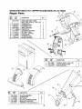
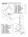
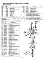
SEARS
CRAFTSMAN
9 H.P. CHIPPER-VACUUM
MODEL
NO. 247.799640
Repair Parts
REF,
NO.
PART
NO.
1 1539-019
2 647-0019
3 649-0008
4 1649-0012
5 681-0076
6 710-0116
7 710-0380
8 710-0621
9 710-0896
10 710-3008
11 71143677
t2
711-0737
13 712-0116
14 712-3004A
15 714-0104
DESCRIPTION
PUSHNUT
CONTROL ASSY
HANDLE ASSY-UPPER
HAN DLE ASSY-LOWER
BRACKET ASSY-SHIFT
SCREW-HEX
SCREW-HEX
SCREW-HEX
SCREW-HEX
SCREW-HEX
FERRULE
PIN-STUD
NUT-HEX LOCK
NUT-HEX LOCK
PIN-COTTER
QTY.
REF.
NO.
PART
NO,
16
17
18
19
20
21
22
23
24
25
26
27
28
29
720-0232
725-0157
735-0126
736-0264
736-0300
736-0413
736-0451
738-0560
738-0561
741-0402
746-0921
747-0626
781-0626
784-0297
4
1
1
1
1
4
2
1
2
4
1
4
1
11
2
t
19
DESCRIPTION
KNOB-SHIFT
CABLE TIE
WASHER, RUBBER
WASHER-FLAT
WASHER-FLAT
WASHER-SPRI NG
WASHER-SADDLE
SCREW-SHOULDER
NUT-SHOULDER
BEARING-FLANGE
PLASTIC
CABLE-CLUTCH
ROD-SHIFT
COVER-SHIFT
HANDLE-SHIFT
QTY.
1
2
1
1
1
2
6
1
1
2
1
1
1
1
SEARS
CRAFTSMAN
9 H.P. CHIPPER-VACUUM
MODEL
NO. 247.799640
Repair Parts
REF.
NO.
PART
1
2
3
4
5
6
7
8
9
10
11
12
629-0241
681-0059
681-0060
710-0382
710-0604
710_607
710-0772
712-1268
710-3008
712-0384
712-0421
712-3004A
NO.
DESCRIPTION
HARNESS--CHIPPER-VAC
HOUSING ASSY--INNER
HOUSING ASSY--OUTER
SCREW-HEX
SCREW-HEX SELF TAP
SCREW-HEX SELF TAP
SCREW-HEX
SCREW-HEX SELF TAP
SCREW-HEX
NUT-HEX LOCK
KNOB
NUT-HEX LOCK
QTY.
REF.
NO.
PART
NO.
1
1
1
2
10
8
3
2
2
2
3
4
13
14
15
16
17
18
19
20
21
22
23
24
712-3010
719-0326
723-0438
725-1700
725-3166
726-0272
731-1613
736-0119
736-0242
781-0598
781-0599
781-0627
2O
DESCRIPTION
NUT-HEX (GR 5)
SCREEN
SEAL-RUBBER
COVER-SWITCH
SNAP MOUNT SWITCH
CLAMP
COVER-SWITCH
WASHER-LOCK
WASHER-BELL
BLADE-FLAfL HOUSING
BLADE-FLAIL HOUSING
COVER-CHIPPER
QTY.
3
1
2
1
1
1
1
3
3
1
1
1
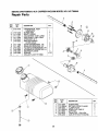
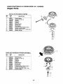
SEARS
CRAFTSMAN
9 H.P. CHIPPER-VACUUM
MODEL
NO. 247.799640
Repair Parts
®
REF.
NO.
PART
NO.
1
681-0078
2
3
4
5
6
7
8
9
10
11
12
710-1273
736-0217
736-0247
681-0078
711-0833A
710-1054
712-0411
715-0249
719-0329
736-0119
742-0544
DESCRIPTION
QTY.
IMPELLER ASSY COMP.
(!NCL. REF. NOS. 2 THRU 12)
SCREW-HEX
WASHER-LOCK
WASHER-FLAT
IMPELLER ASSY
PIN-CLEVIS
SCREW-FLAT HEAD
NUT-HEX LOCK
PIN-ROLL SPRING
BLADE-FLAIL
WASHER-LOCK
BLADE-CHIPPER
1
1
1
1
1
3
4
4
3
3
4
4
®
REF.
NO.
1
2
3
FIEF,
NO.
1
2
3
4
5
PART
NO.
DESCRIPTION
631-0029
731-1616
764-0473
NOZZLE ASS'Y.-VACUUM
CHUTE-DISCHARGE
BAG-VACUUM
PART
NO.
681-0068
710-0258
712-3027
731-1609
781-0625
731-1617
DESCRIPTION
CHUTE ASSEMBLY
SCREW HEX
NUT-LOCK
CHUTE-CHIPPER
UPPER
BRACKET SUPPORT
TAMPER PLUG (Not Shown)
QTY"
t
5
=
\
1
1
1
21
QTY.
1
1
1
SEARS
CRAFTSMAN
9 H.P. CHIPPER-VACUUM
MODEL
NO, 247.799640
Repair Parts
REF. i
PART
NO.
NO.
710-0230
1710-0723
710-0896
711-0758
_
712-0266
712-3004A
719-0330
731-1584
1_
11
12
13
14
15
16
\
\
REF.
NO.
PART
NO,
1 681-0070
2 I'710-0520
3 1710-0924
8
9
10
11
12
13
14
15
16
17
712_3004A
712-3005
1714-0115
i716-0104
720-0236
736-0270
736-0300
736-0369
738-0258
747-0631
750-0985
781-0605
DESCRIPTION
BRKT ASSY--WHEEL
PIVOT
SCREW-HEX
SCREW-MACHINE
PAN HD
SCREW-HEX
FERRULE--ADJUSTABLE
NUT-HEX FLANGE
NUT-HEX FLANGE LOCK
PIN-COTTER
RING-E
KNOB-PLASTIC
WASHER-BELL
WASHER-FLAT
WASHER-FLAT
SCREW-SHOULDER
ROD-ADJUSTABLE
SPACER
BRACKET-HEIGHT ADJ
QTY.
1
1
1
2
1
2
2
1
1
1
1
2
2
1
1
1
1
22
732-0745
736-0329
738-09O8
754-0256
756-0313
756-0649
781-0611
781-0614
DESCRIPTION
SCREW-HEX
SCREW-HEX
SCREW-HEX
NUT-HEX SHOULDER
NUT-HEX LOCK
NUT-HEX LOCK FLANGE
ADAPTER-MOU NTING
COVER-BELT
SPRING-TORSION
WASHER-LOCK
BOLT-IDLER
V-BELT
IDLER-FLAT
PULLEY
BRACKET-IDLER
PIVOT
BRACKET-IDLER
QTY.
1
1
5
1
1
1
1
1
1
1
1
1
I
1
1
1
SEARS
CRAFTSMAN
9 H P CHIPPER,VACUUM
MODEL
NO
247,799640
Repair Parts
8
I
I
,I
i
27
!
I
9
23
SEARS
CRAFTSMAN
9 H.P. CHIPPER-VACUUM
MODEL
NO. 247.799640
Repair Parts
REF.
NO.
PART
NO,
618-0063
2
3
4
5
6
7
8
9
10
11
12
13
14
15
16
17
18
19
618-0168
656-0009
756-0564
738-0865
741-0600
681-0055
681-0058
681-0069
681-0072
681-0073
684-0042
710-0502A
710-0653
710-0788
710-0896
710-3008
711-1026
711-1028
712-0241
712-0711
712-3004A
DESCRIPTION
QTY.
BEARING ASSY-FRICTION
WHEEL
DIFFERENTIAL ASSY COMP.
DISC-FRICTION WHEEL
ASSY COMP.
DISC-FRICTION WHEEL
BOLT-SHOULDER
BEARING-BALL
BRACKET ASSY-SUPPORT
BRACKET ASSY-AXLE
SHAFT ASSY-SHIFT
ARM ASSY-SHIFT
FRAME ASSY
WHEEL ASSY-FRICTION
SCREW-HEX SELF-TAP
SCREW-HEX WASHER
SCREW-HEX WASHER
SCREW-HEX
SCREW-HEX
SHAFT-H EX
i SHAFT-JACK
I NUT-HEX
_
NUT-HEX JAM
NUT-HEX FLANGE LOCK
REF.
NO.
PART
NO.
20 1713-0330
21 713-0374
22 713-0415
23 714-0474
24 716-0102
25 716-0185
26 732-0264
27 736-0105
28 736-0119
29 736-0160
3O 736-0267
31 i736-0287
32 i736-3089
33 738-0908
34 741-0563
35
748-0382
750-0351
36
750-0978
37
750-0979
38
39
750-0980
40
750-0981
41
781-0612
42
784-5590
1
1
1
2
1
1
1
1
4
2
1
8
6
1
1
2
1
5
DESCRIP_ON
SPROCKET & HUB
CHAIN
SPROCKET 11T
P IN-COTTE R
RING-SNAP
RING-SNAP
SPRING-EXTENSION
WASHER-BELL
WASHER-LOCK
WASHER-FLAT
WASHER-FLAT
WASHER-FLAT
WASHER-FLAT
BOLT-IDLER
BEARING-BALL
SPACER
SLEEVE
SPACER
SPACER
SPACER
SPACER
COVER-FRAME
! BRACKE_SHIFT
t QTY.
,
',
E
;I
1
1
1
1
2
1
1
3
2
1
2
4
2
1
2
1
1
1
1
1
1
I
®
REF,
NO.
PART
NO,
1
634-0100
2
3
4
5
6
7
8
9
10
634-0101
734-1598
711-1017
712-3005
714-0104
731-0981A
734-1793
736-0105
736-0232
738-0213
734-0255
DESCRIPTION
WHEEL ASSY COMPLETE
4"X 10"
RIM ASSY COMPLETE
TIRE PNEUMATIC 4" X 10"
PIN-CLEVIS
NUT-HEX FLANGE
PIN-COTTER
HUB CAP
WHEEL 2" X 8"
WASHER-BELL
WASH ER-WAVE
SCREW-SHOULDER
VALVE STEM
t
QTY.
2
2
2
2
2
2
2
2
2
2
2
I
2
24
SEARS
CRAFTSMAN
9 H.P. CHIPPER-VACUUM
MODEL
NO. 247.799640
Repair Parts
REF.
NO.
PART
NO.
618-0168
2
3
4
5
6
7
710-1206
711-1035
711-1037
711-1038
713-0445
716-0232
8
9
10
11
12
13
14
717-1358
717-1437
719 -0333
719-0334
748-0383
737-0300
DESCRIPTION
DIFFERENTIAL ASSY
COMPLETE
SCREW-HEX
SHAFT-CROSS
AXLE-SHAFT 10.95" LONG
AXLE-SHAFT 9.82" LONG
SPROCKET 22 T
RING-RETAINING
(2 PER AXLE)
GEAR-DIFFERENTIAL
14T
GEAR-DIFFERENTIAL
t0T
HOUSING-DIFFERENTIAL
RN
HOUSING-DIFFERENTIAL
LH
BEARING-FLANGE
GREASE
{
SEALANT-LOCTITE
5699
i
/
/
2
2
1
1
2
J-
1 oz
/
.©
REF.
NO.
\
1
2
3
4
5
6
25
PART
NO.
710-3008
712-3004A
726-0205
751-0535-8
751-0603
751-0615
726-0209
DESCRIPTION
SCREW-HEX
NUT-HEX LOCK FLANGE
CLAMP-HOSE
HOSE-FUEL LINE 8"
CAP-FUEL
TANK-FUEL 1 GALLON
CABLE TIE (NOT SHOWN)
QTY.
2
2
2
1
1
1
1
SEARS
CRAFTSMAN
9 H.P. ENGINE
MODEL
NO. 143.959003
Repair Parts
400
305
I
I
" 292
119
_"_
65
296
308
757:
87
7O
69
101
72
26!
I
!
]
f/281282
/
25
26
t82
184
275
.,.>
380/_
_' "" ""
276
277
186
238
239
/
240
242
/
286
251
26
285 €
370e
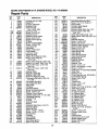
SEARS
CRAFTSMAN
9 H.P. ENGINE
MODEL
NO. 143.959003
Repair Parts
KEY
NO.
l
t
PART
NO.
1
2
4
5
15
35385
27652
32678
30969
30699C
15A
15B
16
17
18
19
20
25
26
28
30
35
36
37
38
40
40
30700
650494
33454
29916
650548
34663
35319
36460
650561
30322
36283
29826
29918
29216
29642
34552
34553
40
41
41
34554
34329A
34330A
41
34331A
42
42
42
43
45
34332
34333
34334
27888
35373A
46
47
48
49
50
60
65
69
70
71
72
75
8O
81
82
83
84
86
87
89
90
92
93
100
101
650908
650882
34034
35374
36569
33273A
650128
35262A
35445A
35377
27642
35319
31845
30590A
35378
30588A
29193
650833
650832
32589
611090
650880
650881
35135
610118
KEY
DESCRIPTION
NO.
102
103
110
119
120
125
125
Cylinder (Incl. 2 & 20)
Dowel Pin
Oil Drain Extension
Extension Cap
Governor Rod
(Incl. 15A & 15B)
Governor Yoke
Screw, 6-40 x 5/16"
Govemor Lever
Governor Lever Clamp
Screw, 8-32 x 5116"
Speed Control Spring
Oil Seal
Blower Housing Baffle
Screw, 1/4-20 x 5/8"
Lock Nut, 8-32
Crankshaft
Screw, 10-32 x 3/4"
Lock Washer
Lock Nut, 10-32
Retaining Ring
Piston, Pin & Ring Set (Std.)
Piston, Pin & Ring Set
(.010" OS)
Piston, Pin & Ring Set (.020" OS)
Piston & Pin Ass'y. (Std.) (Incl. 43)
Piston & Pin Ass'y. (.010" OS)
(Incl. 43)
Piston & Pin Ass'y. (.020" OS)
(Incl. 43)
Ring Set (Std.!,
Ring Set (.010 OS)
Ring Set (.020" OS)
Piston Pin Retaining Ring
Connecting Rod Ass'y. (Incl. 46,
47 & 49)
Connecting Rod Bolt
Connecting Rod Bolt
Valve Lifter
Oil Dipper
Camshaft (MCR)
Blower Housing Extension
Screw, 10-24 x 1/2"
Cylinder Cover Gasket
Cylinder Cover (Incl. 71,75 & 80)
Crankshaft Bushing
Oil Drain Plug
Oil Seal
Governor Shaft
Washer
Governor Gear Ass'y. (Incl. 81)
Governor Spool
Retaining Ring
Screw, 1/4-20 x 1-3/16"
Screw, 1/4-20 x 1-11/16"
Flywheel Key
Flywheel
Lock Washer
Flywheel Nut
Solid State Ignition
Spark Plug Cover
27
PART
NO.
650872
650814
35187
36448
36449
27878A
27880A
126
126
127
128
129
130
135
139
140
149
149A
150
151
169
170
171
172
173
174
178
182
184
185
186
20O
203
204
206
207
209
2!5
223
224
238
239
240
242
245
245A
250
251
260
261
262
34035
34036
650691
650690
650738
650694A
33636
33369
650836
27882
35862
27881
32581
27896A
28423
28424
28425
35350
650128
29752
30088A
33263
34707
34661
34677
31342
650549
610973
33878
650821
32410
650378
27915A
28820
27272A
33266
33267
33268
35881
33269A
650513
333750
650788
29747B
264A
265
275
276
277
281
282
285
650802
33272B
34185B
31588
650729
33013
650760
35985B
DESCRIPTION
Solid State Mounting Stud
Screw, Torx T-15, 10-24 x 1"
Ground Wire
Cylinder Head Gasket
Cylinder Head
Exhaust Valve (Std.) (IncL 151 )
Exhaust Valve (1/32" OS)
(Incl. 151 )
Intake Valve (Std.) (Incl. 151)
Intake Valve (1/32" OS) (Incl. 151
Washer
Belleville Washer
Screw, 1/4-20 x 5/8"
Screw, 5/16-18 x 2"
Resistor Spark Plug (RJ17LM)
Govemor Gear Bracket
Screw, 10-24 x 1/2
Valve Spring Cap
Valve Spring Cap
Valve Spring
Valve Spring Keeper
Valve Cover Gasket
Breather Body
Breather Element
Valve Cover
Breather Tube
Screw, 10-24 x 1/2"
Nut & Lock Washer, 1/4-28
Screw, 1/4-28 x 1"
Carburetor To Intake Pipe Gasket
Intake Pipe
Governor Link
Control Bracket (Incl. 203 & 204)
Compression Spring
Screw, 5-40 x 7/16"
Terminal
Throttle Link
Screw, 10-32 x 1/2"
Control Knob
Screw, Torx T-30, 5/16-18 x 1-1/8"
Intake Pipe Gasket
Screw, 10-32 x 1/2"
Air Cleaner Gasket
Air Cleaner Body
Air Cleaner Bracket
Air Cleaner Filter
Air Cleaner Filter
Air Cleaner Cover
Wing Nut, 1/4-20
Blower Housing
Screw, 5/16-18 x 3/4"
Screw, Torx T-40, 5/16-24 x
21/32"
Screw, 1/4-20 x 5/8"
Cylinder Head Cover
Muffler
Locking Plate
Screw, 5/16-18 x 3-3/16"
Starter Bubble Cover
Screw, 8-32 x 3/8"
Starter Cup
SEARS
CRAFTSMAN
9 H.P, ENGINE
MODEL
NO. 143.959003
Repair Parts
KEY
NO.
286
287
290
292
296
305
307
308
310
325
327
342
PART
NO.
35446
29752
30705
26460
34279B
35554
35499
35540
36205
29443
35392
30063
Starter Screen
Nut & Lock Washer, 1/4-28
Fuel Line
Fuel Line Clamp
Starter Screen
Oil Fill Tube
"O"-Ring
Fill Tube Clip
Dipstick
Wire Clip
Starter Plug
Screw, Terx T-30, 1/4-20 x 1/2"
RPM Setting:
High Speed: 3450 to 3750
Low Speed: 1700
Y
L
PART
NO.
632689
6
7
10
11
12
13
14
15
16
17
632243
632244
631184
631183
632517
650506
632249
632043
631184
631183
632248
630735
632164
650417
630766
632281
630766
630739
630740
631867
631024
632019
631028
631021
631022
632239
630740
630739
630738
27110
630748
631027
632347
KEY
NO.
DESCRIPTION
,
PART
NO.
370
370A
370B
370C
380
390
DESCRIPTION
36261
Instruction Decal
35703
Throttle Decal
35532
Logo Decal
35274
i Instruction Decal
632689
Carburetor (Incl. 184)
590671
Rewind Starter
Note: This engine could have been built
with 590704 starter. Refer to the design of the
air intake louvers for part identification.
Individual starter parts do not interchange.
36454
Gasket Set
400
**(Incl. Part Nos. 27272A, 27896A, 27915A,
29673, 33263, 33629, 34698A, 35262 & 36448)
Part SPARK
No. 34479A
I OPTIONAL
ARRESTER
DESCRIPTION
Carburetor (Incl. 184 of Engine
Parts List)
Throttle Shaft & Lever Assembly
Throttle Return Spring
Dust Seal Washer
Dust Seal (Throttle)
Throttle Shutter
Shutter Screw
Choke Shaft & Lever Assembly
Choke Return Spring
Dust Seal Washer
Dust Seat (Choke)
Choke Shutter
Choke Positioning Spring
Fuel Fitting
Throttle Crack Screw/Idle Speed
Screw
Tension Spring
Idle Mixture Screw
Tension Spring
Idle Mixture Screw Washer
Idle Mixture Screw =O"-Ring
Float Bowl
Float Shaft
Float
Float Bowl "O"-Ring
Inlet Needte, Seat & Clip
(Incl. 31)
Spring Clip
Main Adj. Screw Ass'y. (Incl. 41
thru 44)
High Speed Mixture Screw
"O'-Ring
High Speed Mixture Screw
Washer
High Speed Mixture Screw
Tension Spring
Bowl Nut Washer
Welch Plug, Idle Mixture Well
Welch Plug, Atmospheric Vent
Repair Kit* (Incl. Items Marked
PK in Notes)
28
I
SEARS
CRAFTSMAN
9 H.P. ENGINE
MODEL
NO. 143.959003
Repair Parts
PARTS LIST FOR RECOIL STARTER
KEY
NO.
m
1
2
3
4
5
6
7
8
11
12
13
PART
NO.
590671
590599A
590600
590679
590601
590678
590680
590412
590681
590683
590456
590387
DESCRIPTION
Recoil Starter
Spring Pin (Incl. 4)
Washer
Retainer
Washer
Brake Spring
Starter Dog
Dog Spring
Pulley & Rewind Spring Ass'y.
Starter Housing A,s,s'y.
,
Starter Rope (114 x 11/64 Dia.
Starter Handle
_'_4
--11
PARTS LIST FOR RECOIL STARTER
KEY
NO.
m
1
2
3
4
5
6
7
8
11
12
13
PART
NO.
590704
590599A
590600
590696
590601
590697
590698
590699
590700
590705
590535
590701
(OPTIONAL)
DESCRIPTION
Recoil Starter
Spring Pin (Incl. 4)
Washer
Retainer
Washer
Brake Spring
Starter Dog
Deg Spring
Pulley & Rewind Spring Ass'y.
Starter Housing Ass'y.
Starter Rope (98" x 9/64" Dia.)
Starter Handle
O--2
29
Seal kits for the new cylinders are the same as for the old cy ind.ers_ as a!l me internal components are the same,
bore diam
4,0"
4.5"
To;
old cylinder
718-0307
718-0306
new c_inder
718-0773
718-0769
DISTRIBUTORS
¸
LOG
Re:
sealkit
753-0490
753-0563
& AUTHORIZED
SPLITTER
SEAL
SERVICE
DEALERS
KITS
As of February 1. 1999. log splitter cylinders under warranty capable of being repmred with a seal
kit must be repaired. Any cylinders replaced under warranty will be called back for inspection. Any
cylinder found to be repairable will be returned to the dealer and the dealer will be charged back the
amount paid on the claim for the cylinder. Labor already paid will not be charged back. If replacement is
determined to have been the only solution to the problem, no action will be taken. If you have any
questions regarding this policy or how to handle a situation please contact MTD service.
If you need a pressure test kit (part # 759-3742),
contact your central distributor.
This kit includes
an ins,_"uc=ional video and is a,:ailable for loan or purchase.
You will be rei_b'arsed
for t_hc cost of
shipping
and handling on a warranty job if you used a test kit on loan and include the amount on the claim
form.
Seal kits are as follows.
Md_J
Fisher cylinders
(retaining
ring end cap):
CYLINDER NUMBER
CYLINDER I.D.
SEAL KIT
_z._,...>718-0306
4.5"
753-0563
_zb-e
4.0"
753-0490
753-0637
75320564
718-0307
718-0312
4.25"
718-0313
5.0"
Best Metal
CYL NDER
cylinders
NOMBER
(thread
[ CYLINDER
on end cap):
I.D.
SEAL KIT
718-0307
[
4.0"
753-0689
718-03'13
!
5.0 _''
753-0691
Procedure
(On Machine
for Resealing
- Fisher
Hydraulic
Cylinders
Cylinders
- Snap-Ring
Type)
1.
Clean cylinder, wedge and beam area.
2.
Fully retract cylinder rod into cylinder - stop engine.
3.
With engine off, move control valve back and forth several times to be sure there is no pressure in system.
4.
With a clean catch container in place, disconnect pump to control valve hose from pump fitting and in_ert end
into container. Plug fitting on pump with plastic cap or tape. This is to prevent dirt from entering fitting,
5.
Remove (4) ¥I" bolts securing the log dislodger and remove dislodger.
6,
Remove %" bolt through wedge and cylinder rod. Slide wedge all the way forward on the beam till it meets the
base plate. No need to remove wedge from beam,
Z.
Lift rod up and place wood block under cylinder barrel to hold assembly at an angle, This will allow for rod
removal
8.
Place control valve into detent position
9,
Using a wood dowel or a hammer handle, tap cylinder rod cap into cylinder just beyond the snap ring. Do not go
any farther than necessary as it will make further disassembly very dit_cult. Remove snap ring from groove
being careful not to scratch groove or bore. If you do, you must polish scratched area with fine emery so scratch
won't damage new seals as they pass the area It is an easy job if you tap one end of snap ring into the cylinder
first, and then get a medium screwdriver under the ring to pry it our.
10.
Reconnect
and tighten hose to pump.
11. Very
lmportantH!!
You must clean any paint or rust in the bore area by sanding it off. The paint wi}l be from
the snap ring groove outward. After removing ALL uaint and rust leaving a smooth surface, coa_ exposed area
inside cylinder with grease If you do not do this, fiJrther disassembly will be difficult and damage may result
during reassemhIy!
USE EXTREME
12.
CAUTION
DURING
NEXT
STEP).). ).
Put control lever in neutral and start engine. Set engine at low idle speed, and use control valve lever 1o extend
rod out of cylinder until cylinder rod cap just starts to move. Put control lever in neutral, shut off engine and
disconnect spark plug wire.
13. Have someone hold control lever in extend position and pull engine starter rope to extend rod slowly until the
cy [nder rod cap can be pulled free of the cylinder.
Do not remove end cap from rod.
14. Remove steel tube from fitting at end of cyl_nder and attach a ¾'" I.D. hose to fitting on the e_ linder using a hose
damp. Place other end of hose into catch container.
15. Push rod into cylinder using cylinder rod cap as a guide. This will force oil out of cylinder through hose and into
container. Do nol push turn down of rod into cylinder rod cap as damage to cap may result. Remove hose from
cylinder.
16. You are now ready to pull rod and piston assembly from cylinder barrel_ Be sure to have a piece of wood, thick
cardboard or pile of rags on the beam so that when you pull the rod out of the cylinder the piston won't be
damaged by droptfing down on the beam Install a suitable bar or large screwdriver through bolt hole in rod and
pull rod, cylinder rod cap and piston out of cylinder.
17". Set rod and piston assembly on clean bench and with a light examine inside of cylinder barrel for gouges and
scratches. If scratches exist you should replace the complete cylinder. Do not attempt to hone cylinder as any
reduction of wall thickness can result in a safety problem, If no damage to cylinder is apparent, proceed with
repair.
18.
Prop cylinder up as close to vertical as possible with a wood block.
19.
Bolt rod to wedge ram placing a wood block under rod to keep piston from hitting beam. Remove nut from
piston end of rod and slide piston and cylinder rod cap off threaded end of rod.
20. Examine piston and rod cap for damage.
Remove old seals, bearings and o-rings from rod, pisto_ and cylinder
rod cap. Pay attention to alignment of seals as some are directional. Be very careful not to scratch the walls
of the seal grooves. Scratches can render the rod cap or piston unusable.
21.
Using a tap and die or thread file, clean threads on rod and nut.
22. Cleanliness
is vital throughout
reassembly!
Clean piston,
rod, end cap and cylinder.
23. Lubricate seals and bearings with hydraulic oil and install them in end cap and piston.
24. Lubricate inside of cylinder rod cap and piston with general purpose grease and carefully install them on rod from
threaded end being careful to start wiper lip onto rod and then working cylinder rod cap on. Any attempt to
install the cap from the rod turn down end will result in seal lip damage.
25.
26.
Clean grease from exposed threads on rod and install piston nut on rod using red Loctite. Torque nut to
300 - 325 ft.-lbs, and restake in place to prevent the nut from backing off.
Remove rod assembly from wedge and set aside in a clean place being careful not to damage seals. Lower
cylinder to angle at which rod may be reinserted.
27..Lubricate
28.
inside of cylinder _t__'thhydrau!{c oil and grease the end cap and piston.
Insert piston into cylinder being careful to not damage seals. Slide assembly in until piston is approximately
into barrel, then slide rod cap into cylinder and tap it injust past snap ring groove. Do not go farther than
necessary to install snap ring as damage to seals may occur, install snap ring.
12"
29. Place control valve in neutral. Reattach tube to cylinder and wedge to rod.
30.
Add oil to tank to within 1" from top. Start engine and slowly cycle control valve several times to fill cylinder.
There will be a !oud "POP" as cylinder rod cap seats over snap ring. (Cylinder may act jumpy until cylinder self
purges of air.) When cylinder is full, retract ram fully and stop engine. Top offoil to within 1.5" to 2" from top
of tank.
3 I. Remove wedge from rod and prop cylinder up again. Clean and paint area of cylinder bore you originally sanded.
32.
Complete reassembly,
cycle unit and check for leaks. If possible, test on a few logs.