1
8! 8
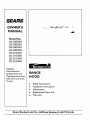
OWNER'S
MAN UAL
Model Nos.
233.52052002
233.52053002
233.52057002
233.52059002
233.52152002
233.52153002
233.52157002
233.52159002
Caution:
Read and follow
all Safety Rules and
Operating Instructions
before first use of this
RANGE
HOOD
Product.
•
.
•
Safety Instructions
Installation Instructions
Maintenance
•
•
Replacement Parts List
Warranty
Sears, Roebuck and Co., Hoffman
Estates, IL 60179 U.S.A.
IMPORTANT
SAFETY
INSTRUCTIONS
IMPORTANT
SAFETY
INSTRUCTIONS
WARNING
CAUTION
WARNING
-TO
II_LIRYTO
PERSONS, OBSERVETHE
REDUCE THE RISK OF FIRE, ELECTRIC SHOCK, OR
1.
For general ventilating
or explosive materials
2.
To reduce the risk of Rre or electrical shock,this
not be used with an additional
speed control
FOLLOWING:
not use to exhaust
hazardous
range hood should
device.
1.
Use this unit only in the manner intended
by the manufacturer.
you have questions,
contact
the manufacturer
at the address
telephone
number listed in the warranty.
3.
To reduce
2.
Before servicing or cleaning unit, switch power off at service panel
and lock service panel to prevent power from being switched on
accidentally. When the service disconnecting
means cannot be
locked,securely
fasten a prominent
warning device,such
as a tag,
to the service panel.
.
4.
To reduce the risk of fire and to properly
duct air outside.
3.
Installation work and electrical
wiring must be done by a qualified person(s)
in accordance
with all applicable
codes and standards, including fire-rated construction
codes and standards.
Recommended
mounting
height is 18 _to 24 _from the bottom
range hood to the top of the cooking surface.
4.
Sufficient air is needed for proper combustion
and exhausting
of
gases through the flue (chimney)
of fuel burning equipment
to
prevent
backdrafting.
Follow
the
heating
equipment
manufacturer's
guideline
and safety standards
such as those published by the National
Fire Protection
Association
(NFPA), and
the American
Society for Heating, Refrigeration
and Air Conditioning Engineers
(ASHRAE), and the local code authorities.
5.
When cutting or drilling into wall or ceiling,
trical wiring and other hidden utilities.
6.
Ducted
7.
To reduce the risk of fire, use only metal
TO REDUCE
1.
2.
fans must always
be vented
do not damage
If
or
use only.Do
and vapors.
cooking
3.
Clean ventilating
fans frequently.
to accumulate
on fan or filter.
4.
Use proper pan size.Always
size of the surface element.
uSe cookware
should
cook-
not be allowed
appropriate
for the
TO REDUCE THE RISK OF INJURY TO PERSONS IN THE EVENT
OFA RANGETOP
GREASE FIRE, OBSERVETHE
FOLLOWING*:
1.
SMOTHER FLAMES with a close-fitting
lid, cookie sheet, or metal
tray, then turn off the burner. BE CAREFULTO PREVENT BURNS.
If the flames do not go out immediately,
EVACUATE AND CALL
THE FIRE DEPARTMENT.
2.
NEVER PICK UP A FLAMING PAN -You may be burned.
3.
DO NOT USE WATER, including
wet dishcloths
lent steam explosion
will result.
4.
Use an extinguisher
or towels
- a vio-
ONLY if:
A. You know you have a Class ARC extinguisher,
and you already know how to operate it.
B. The fire is small and contained
in the area where it started.
C. The fire department
is being
called.
D. You can fight the fire with your back to an exit.
• Based on _Kitchen
Fir_safetyTips
_ published
by NFPA.
servicing.
air, be sure to
of the
All wiring must comply with local codes and the unit must be properly grounded.The
hood is connected
to a 110-120vAC lighting circuit (15 amp) in the circuit breaker or fuse box.
This range hood is "Convertible'a non-ducted
unit.
Purchase
IFTHE
at high settings. J3oilovers
that may ignite. Heat oils
Grease
before
exhaust
The hood should be mounted
to the bottom of a standard wall cabinet. If the hood must be mounted
directly to a wall, secure the hood
to wall studs.
•
ductwork.
at high heat .or when
power
PLAN THE INSTALLATION
IFTHE RANGE HOOD
THE RISK OF A RANGE TOP GREASE FIRE:
Always turn hood ON when
ing flaming foods.
disconnect
it may be installed
as a ducted
or as
elec-
to the outdoors.
Never leave surface units unattended
cause smoking and greasy spillovers
slowly on low or medium settings.
the risk of shock,
ISTO BE NON-DUCTF,
nonMucted
RANGE HOOD
(duct-free)
ISTO
can be installed
charcoal
D:
filter Model BPQTE
BE DUCTED:
•
Ductwork
•
Duct runs should
vertically
•
Avoid the use of elbows.
•
Use duct tape at all joints.
•
Do not use duct smaller
•
For 7" round ductwork installation,
BP87 (purchased
separately).
Be as short
or horizontally.
as possible.
than the discharge
on the hood.
use 7 _round
damper,
Model
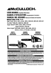
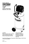
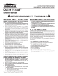
HORIZONTAL DISCHARGE
THROUGH WALL
CUTOUT DIMENSIONS
/
WALL
KITCHEN
CABINET
SUPPUED DUCT
TRANSmON
DD
WALL CAP
7½"
RANGEHOOD
/
5¼"
__ w_&
In[G_
VERTICAL DISCHARGE
USING 3V4" x 10" DUCT
I
ROOF CAP
CUTOUT DIMENSIONS
T
TOP
VIEW
9"
_'J/I--_"="I_L L,.
BACK
VIEW
1
a!'{] ELEC.K.O._
r--3/_"
--
_
",.I
t-11/2"
T
EAVE CAP
3Y4"X 10"
DUCT
WALL CAP
SUPPLIED DUCT
TRANSITION
WALL
RANGE
HOOD
VERTICAL DISCHARGE
USING 7" ROUND DUCT
ROOFCAP
CUTOUT DIMENSIONS
ADJUSTABLE
ELBOW
CL
_""ROOF
TOP
VIEW
17 =
7"ROUND
DUCT
REMOVE BOTH
3½" x 10" AND7"
HALF ROUND
KNOCKOUTS FOR
7" DUCT
9"
_.J/'l-_,,,::
BACK
VIEW
J
TDL_
X_-
,o-
,,..
I
Lll/2 .
IF_
7"ROUND
DAMPER
_UPPLIED
7" ROUND
DUCT TRANSITION
RANGE
HOOD
_GtrBLE 3
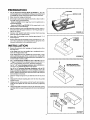
PREPARATION
1.
LOCATORS
Use the dimensional
drawings
out the range hood's mounting
by marking the cabinet bottom
for wiring
(Refer to FIGURES 1 - 3) to lay
holes, vin'ing access and ductwork
and drywall where applicable.
2.
Make cutouts
3.
If the hood is to be ducted,install
the ductwork
the range hood's mounting
surface.
Refer to FIGURE
horizontal
discharge.
Refer
installed
BAFFLE PLATE
and ductwork.
1 if the range hood
so that is flush to
is to be installed
to FIGURE 2 and FIGURE 3 if the range
with a vertical discharge.
with a
hood
is to be
4.
Run two-conductor
wire (with ground) from a power source to
the hood location.B(mg
approximately
12"of wiring through wiring hole in cabinet.
5.
DriU four 3/32" diameter
pilot holes
holes are marked in cabinet bottom.
6.
Insert four (4) mounting
thread exposed.
7.
Remove and retain the mounting
screws securing the 3¼"x 10"
and 7 _ duct transitions to the hood. Install the appropriate
duct
transition
as described
in the installation
section.
screws,
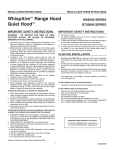
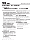
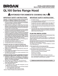
I N STALLATIO
1.
_
Remove the necessary
the range hood.
at points
leaving
where
FIGURE
approximately
¼" of
ADAPTER
(Included)
N
duct opening
If the range hood is to be installed
move the wiring knockout
only.
and wiring
knockout
as a non-ducted
from
unit,
re-
If the range hood is to be installed
as a dueted
unit, a baffle
plate is provided
to close off the nonMucted
vent. InstaB baffle
plate (Refer to FIGURE 4) by sliding into place behind grille. Use
locator bumps to orient in grille.
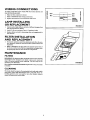
2.
FIGURE
For 7" round discharge
installation,
refer to FIGURE 5. Secure
7" adapter (included)
to top of hood using screws provided, install 7" round damper (Model BPg7, purchased
separately).
For 3V_x 10" vertical _
cure 3¼" x 10" transition
4
mounting
5
SECURE TRANSITION
installation, refer to FIGURE 6. Se(if used) to top of hood.
T
WITH SCREWS (Included)
For 3_i" x 10" horizontal
discharge
installation,
refer to FIGURE 7. If using the supplied 3¼ _ 10" duct transition, remove the
damper flap from the transition to prevent possible venting interference. Position transition into wall cutout. Note:The
transition
does not fasten to the hood.
3.
Feed the wiring
box.
through
the access
4.
Align hood's keyhole
installed screws.
5.
Making sure the duct positions
over the hood's duct transition,
push the hood against the rear wail. Secure hood by tightening
mounting
slots
hold
and into the electrical
over the four (4) partially
FIGURE
SCreWS.
6.
Using a long blade screwdriver,
reach into the discharge opening
and make sure the damper flap operates freely (vertical discharge
only).
POSITION DUCT
TRANSITION iN
WALL CUTOUT
÷,°
HORIZONTAL
FIGUILE7
6
WIRING
CONNECTIONS
All wiring connections
must comply
must be properly grounded.
1.
Make sure box connector
2.
Refer
3.
Replace
local
codes
O
and the unit
box cover
WHT
BLK
O
O
connections.
and secure
with
screw.
LAMP INSTALLING
OR REPLACEMENT
Depress sides of light diffuser until tabs of diShlser disengage
slots in hood. Remove diffuser.
2.
Install
3.
Replace difuser
slots in hood.
in hood
i
WHT
•
.
:GREEN_ROUND:
:SCREW
:
:
_-"_OR
..............
:
BLK
GREEN
BARE
(GROUND)
O
FIGURE8
1.
(2) 40 watt maximum,Type
0'J
'
is secure.
to FIGURE 8. Make wiring
electrical
with
A-15 appliance
by depressing
from
bulbs.
sides and engaging
tabs in
FILTER INSTALLATION
AND REPLACEMENT
1.
For ducted operation, install the aluminum
mesh filter. For nonduct operation,
install the non-ducted
filter (Model 50190, sold
separately).
2.
Refer to FIGURE 9. The filter slides into channels at the back of
the hood,on either side of the fan compartment,and
snaps under
the spring clips near the front of the fan compartment.
MAINTENANCE
FILTERS
IMPORTANT:The
aluminum
filter should be removed once monthly
and washed in hot detergent water. Rinse in clear, warm water and
shake off excess moisture
before replacing.
The fdter may also be
cleaned in your dishwasher.
INA NON-DUCTED
as needed.
INSTALLATION:Replace
FIGURE
filter every 3_ months
CLEANING
The hood should be wiped off occasionally
both inside and outside
using warm water, mild dish detergent
and a soft cloth. Never use
scouring
powders,
steel wool pads or any other abrasive cleaners
which will destroy the hood's finish.
5
9
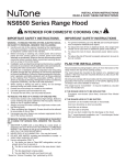
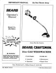
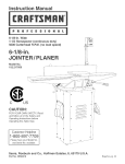
SERVICE
PARTS
16
12
11
13
KEY NO.
PART NO.
1
2
99080532
R99020277
R99420635
99271236
NTK3720-000
R561138
NTK4402-000
97015294
98009816
RK7694-000
RK7693--000
RK7692-000
NTK6630-000
NTK7474-000
NTK7472-000
NTK7473-000
NTK7540-000
NTK7539-000
NTK7541-000
R401606
99010316
99010317
97005544
R680508
3
4
5
7
8
9
11
12
13
15
16
DESCRIPTION
Motor
Fan Blade
External Hitch Pin (Hairpin)
Lamp Socket (2 Required)
Fan Switch Assembly
Light Switch
Rectifier Assembly (Night-Light)
Light Lens Assembly
Wiring Cover
Grille (Black)
Grille (White)
Grille (Almond)
Palnut (4 Required)
Knob (Black)
Knob (White)
Knob (Almond)
Baffle (Black)
Baffle (White)
Baffle (Almond)
Baffle (Biscuit)
Aluminum Filter
NomDucted Filter (Purchased separately)
31,_"x 10" Transition
7" Round Transition
Order replacement parts by PART NO. - not by KEY NO.
* Not illustrated
WARRANTY
LIMITED WARRANTY
If within 1 year from the date of installation, any part of this range hood fails to function properly due
to a defect in material or workmanship, Sears will repair the part or furnish and install a new part,
free of charge.
FULL 30-DAY WARRANTY ON FINISH ON PAINTED OR BRIGHT METAL PARTS
If within 30 days from the date of installation, the finish on any painted or bright metal parts of this
range hood is defective in material or workmanship, Sears will furnish and install a new part, free of
charge.
WARRANTY SERVICE IS AVAILABLE BY CONTACTING THE NEAREST SEARS SERVICE CENTER/DEPARTMENT IN THE UNITED STATES.
This warranty applies only while this product is in use in the United States. This warranty gives you
specific legal rights and you may have other rights which vary from state to state.
Sears, Roebuck and Co., Dept 817WA, Hoffman Estates, IL 60179
SEARS
OWN E R'S
HANUAL
Model Nos.
233.52052002
233.52053002
233.52057002
233.52059002
233.52152002
233.52153002
233.52157002
233.52159002
The model number of your
range hood is found on a
label inside the hood.
RANGE
HOOD
For the repair or replacement parts you need
CaU 7 am - 7 pro, 7 days a week
1-800-366-PART
(1-800-366-7278)
For in-home major brand repair service
Call 24 hours a day, 7 days a week
1-800-4-MY-HOME s"
(1-800-469-4663)
For the location of a
Sears Parts end Service Center
in your area
Call 24 hours a day, 7 days a week
1-800-488-1222
When requesting service
or ordering parts, always
provide the following
information:
A
For more information on purchasing a Sear_
Maintenance Agreement or inquire
about any existing Agreement
Call 9 am * 5 pro, Monday-Saturday
_
_Ai_A_,
L
1-800-827-6655
•
•
•
Product Type
Model Number
Part Number
•
Part Description
HomeCentral
J
The ServiceSideof Sear"
Sears, Roebuck
Printed in U.S.A.
626875
and Co., Hoffman
Estates,
IL 60179
U.S.A.
99043037A
SEARS
MANUAL
DEL DUENO
N
Modelos Nos.
233.52052002
233.52053002
233.52057002
233.52059002
233.52152002
233.52153002
233.52157002
233.52159002
Advertencia:
Lea y siga toclas las
reglas de seguridad y
las instrucciones de
CAMPANA
DE COCINA
operacibn antes de
usar este producto
por primera vez.
Sears, Roebuck
•
•
•
Instrucciones de Seguridad
Instrucciones de Instalaci6n
Mantenimiento
•
•
Piezas de Repuesto
Garantia
and Co., Hoffman
Estates,
IL 60179
U.S.A.
INSTRUCCIONES
DE SEGURIDAD
INSTRUCCIONES
DE SEGURIDAD
ADVERTENCIA
PRECAUCION
CUIDADO
ELE_CA,
1.
2.
3.
4.
- pARA REDUCIR EL RIESGO DE FUEGO, DESCARGA
O LES1ONESA PERSONAS, OBSERVE LO SIGUIENTE:
Use esta unidad solametate eta la manera a la que fue destinada
pot el fabricante. Si tiene cualquicr pregunta,p6ngas¢
eta contacto con el fabricante
a la direcci6n y tel_fono enlistado en la secci6ta de la garantla.
Antes de dar servicio o limpiar la utaidad, apague la entrada de la
potetacia el_ctrica
en el panel de servicio y ci_rrelo con Have
para prevenir que alguien prenda la potencia
accidentalmente.
Una persona calificada debe de hacer el trabajta de instalaci6n
del
cableado el_ctrico de acuerdo con los c6digos y est_mdares aplicables.
3.
Utilice un sart_n de tama6o
8o adecuado
al tama6o del
PARA REDUCIR EL RIESGO DE
DE UN INCENDIO DE GRASA
LO SIGUIENTE:*
adecuado.
Siempre utilice el utensielemento de superficie.
LESIONESA PERSONAS FJNEL CASO
ENCIMA DE LA ESTUFA, OBSERVE
1.
AHOGUE [.AS LLAMAS con una tapa que cierra apretadamente,
una hlmina pafa galletas tauna bandeja de metal y entota¢es apague el quemador. ESTE SEGURO EN NO QUEMARSE. Si las llamas
no se apagan h_nediatamente,
DESOCUPE LA COC1NAy CASAY
LLAMEA LOS BOMBEROS.
2.
NUNCA LEVANTE UNA OLLA QUE ESTE INCENDIANDOSE
ted puede quemarse.
3.
NO USEAGUA, incluyendo
trapos o toallas mojadas
los resultarfi en una explosi6n
violenta.
Use un extinguidor
SOLAMENTE si:
4.
A. Usted sabe que tietae un extinguidor
ya sabe c6mo operarlo.
B. E1 fuego
menz6.
es pequefio
C. Se est_ llamando
D. Usted puede
una salida.
y est_ contetaido
el fuego
con su espalda
Compre
Modelo
DE COCINA
un fdtro
BPQTE
Sl LA CAMPANA
desconecte
DE COCINA
•
Los conductos
pueden
•
•
LoS tramos de ¢onducto
Evit¢ el uso de codos.
instalarse
NO SE CONECTA
de carb6n
• Use cinta para conductos
la alimetatapara
el
sin conductos
SE CONECTA
instalarse
deben
vertical
como
una
A CONDUCTOS:
(libre de conducttas)
A CONDUCTOS:
o horizontalmetate.
set tan cortos
como sea posible.
en todas la juntas.
• No use un conducto mils peque (o que la descarga de la campana).
• Para instalacidn
de cotaductos
circulares
de 17,78 (7"), use un
regulador
circular
de 17,78 cm (70, Modelo BP87 (comprado
separademente).
y usted
co-
hacia
• Ba._ado en los _Kitchen Ftresafety Tips" (Cotasej os para Seguridad
Fuego eta la Cocina) publicado
pot la NFPA.
Asegfrese
de agotar el aire por cotaductos
hacia el exterior,
redocir el riesgo de itacendio y para agtatar apropiadamente
aire.
•
a los bomlmros.
tratar de apagar
4.
Sl I.A CAMPANA
- Us-
en el _rea donde
Para reducir el riesgo de electrocuci6ta,
ci6n antes de prestar servicio.
Esta campana de ctacina es "convertible
_, puede
unidad conectada
o no conectada
a conductos.
ya que el usar-
de la ClaseABC
3.
se debe
de con-
Todo el cableado
debe cumplir con las c6digos locales y la unidad
debe estar adecuadamente
conectada
a tierra. La campataa
est
conectada
a un circuito de fluminaci6n
de 110-120VCA (15Amp)
en
el interruptor
de circuito o caja de fusibles.
cocin¢ con alta tempeeapuedata incendiar.
No debe permitir que la
el filtro.
4.
Para reducir el riesgo de incendio o de electrocuci6n,no
usar la eampana de esa cocina con un elementta adicional
trol de velocidad.
La campana debe montarse eta la parte inferior de un armario normal
de pared. (Asegure la campana a los pernos de montaje de la pared, si
la campataa debe montarse
directamente
en la pared.).
Nunca deje sin atender las unidades de superficie cuando tengan
ajustes altos. Los reboses pueden provocar humo y dcrrames
grasosos que se pueden incendiar. Caliente letatametate el aceite
en tm ajuste bajo o medio.
Siempre ENCIENDA la campana cuando
tufa o cuando cocine alimentos quc se
Limpi_ con frecuencia
los ventiladores.
grasa se acumule en el ventilador
tai en
2.
La ahura recomendada
para montaje es de 45,72 a 60,96 cm (18 a 24
pulgadas) desde la parte inferior de la campana de la cocina hasta la
parte superior de la superticie
para cocinar.
Cuando corte o perfore una pared o techo, no haga dafio a los
alambres el_ctricos
y otras instalaciones
ocultas.
6. Ventfladores
o abanicos
que usan ductos debcn siempre descargar el aire al exterior.
7. Para reducir el riesgo de fuego use solamente
ductos de metal.
PAIL&REDUCIR EL RIESGO DE UN INCENDIO DE GRASA ENCIMA DE LA ESTUFA:
2.
Para uso de vetatilaci6n general solamente.
No 1o use para extraer
materiales
o vapores explosivos
o peligrosos.
PLANEAMIENTO
Para cualquier
equipo que quema combustible
es necesario
teher el aire suficiente
air€ para que haya combusti6n
apropiada
y
salida de los gases a tray,s de la chimenea y as[ prevenir que estos
gases se regresen. Siga las directivas
del fabricante
del equipo de
calentar
y los est_lndares
de seguridad
como los que ban sido
publicados
por la National Fire Protection
Association
(NFPA)
(Asociaci6n
Nacional
de Protecci6n
de Fuego) y la American
Society for Heating, Refrigeration
and Air Conditioning
Engineers
(ASHRAE) (La Sociedad Americana
de lngenieros
para Calefacci6n, Refrigeraci6n
y &ire Acotadicionado)
y las autoridares
de
c6digo locales.
5.
1.
1.
de
10
DESCARGA HORIZONTAL
A TRAVES DE LA PARED
DIMENSIONES DE LA SALIDA
dk/1
ARMARIO
DE COCINA
PARED
TRANSICIOR
PROV|STA PARA
EL CONDUCTO
b/
CAMPANA
DE COCINA
__
_I,91 cn
TAPA DE
PARED
9,84 cm
()RIFICIO PARA
_13,3
EL CARLEADO
cm
DESCARGA
VERTICAL
UN CONDUCTO
USANDO
TAPA E TECHO
DE 8,26 cm x 25,40 cm (3Y4 x 10")
DIMENSIONES DE SALIDA
_ 2, s4m
L
,ORI_
TAPA DE ALERO
t "',,
'-:o,'
---_/I-,,..
J=
CONDUCTO
8,26 cm x 25, 40 cm
L
t
TRANSIC|ON
PROVISTA
IJ1m
VISTA ,,9,.__ ELEC,
K.,_.
I "
TAPA DE PARED
,OSTER,OR
t--_:O1..__.l
PARED
CAMPANA
DE COClNA
FIGURA2
DESCARGAVERTICALUSANDO
UN CONDUCTO
CIRCULAR
DE17,78cm(7")
CODO
__It/TAPA
DE TECHO
DIMENSIONES DE SALIDA
._-2,s4cm
AJUSTABLE//
i
CONDUCTO
CIRCULAR
DE17,78 cm
su,,R,O, l i-lo j ____,....
---J
VISTA
"=' ©._
/ I--I.-.I
ELEC.K_, I
=m
==.
CL
_TECHO
t
QUITE AMBAS TAPAS DE
AGUJEROS PREPUNZADAS,
LA DE 8,26 cm x 25,4 cm y EL
MEDIO CIRCULO DE 17,8 cm
DE DIAMETRO
REGULADOR
CIRCULAR
DE 1;
11,111_
-
_ANSICION
! ........ -_ ""_"
POST.OR
,---I---:?r--_ I
'I
DE
COCINA
CAMPANA
j
CIRCULAR DE
17,76 cm PROVISTA DE
CONDUCTO
lqGURA
11
3
PREPARACION
1.
2.
Efecto e los cortes
3.
lnstale el conducto de manera que est_ al r-ascon Ja superlicie
de
montaje de la campana de cocina, si la campana se conecta
a un
conducto.
para el cableado
Si la campana
refi_rase alas
_
PLACA
DEFLECTORA
y el conducto.
Si la campana de la cocina se instala
tal, refi&ase a la FIGURA 1.
4
LOCALIZADORES
Use los dibujos dimensionales
(FIGURAS 1 - 3) para disponer los
orificios de montaje de la campana, acceso del cableado y conduetos, marcando el rondo del armario y el tabique donde sea
aplicable.
con una descarga
horizon-
de la cocina se instala con una descarga
FIGURAS 2 y 3.
vertical,
Tienda un cable de dos conductores
(con conexi6n
a tierra) desde una fuente de potencia
a la ubicaci6n
de la campana.Traiga
30,48 cm (12") de cableado aproximadamente
a tray, s del orificio de cableado en el armario.
FIGURA
Taladre cuatro orificios piloto de 0,24 cm (3/32") de di_metro en
los puntos donde est_n marcados
los orificios de montaje en el
rondo del armario.
6.
lnserte cuatro (4) tornillo de montaje,dejando
0,64 cm (1/4") de rosca expuesta.
7.
Extraiga y guarde los tomillos de montaje, asegurando
las transiclones de conducto
de 8,26 cmx 25,40 cm (3¼" x 10") y 17,78
cm (7") a la campana.lnstale
la transici6n de conducto
apropiada
segfin se describe en la secci6n de instalaci6n
4
ADAPTADOR
DE 17,78 cm (7")
(Incluldo)
aproximadamente
INSTALACION
1.
Extraiga la abertura de conducto
y el orilicio
necesarios,
de la campana de cocina.
ciego de cableado
FIGURA
5
Si la campana
de cocina
se instala como una unidad sin conductos, extraiga el orificio ciego del cableado
soiamente.
Si la campana
de cocina se instala como una unidad con conducto, s¢ provee una placa deflectora
para cerrar el ventilador
sin conducto.
Instale la placa deflectora
(refi_rase
a la FIGURA
4) deslizando en su lugar detros de la rejilla. Use las salientes del
localizador
para orientar en la rejilla.
2.
ASEGURE LA TRANSICION
CON LOS TORNILLOS (Incluido$)
Para una instalaci6n
de descarga
circular
de 17,78 cm (7"),
refi_rase a la FIGURA 5.Asegure
el adaptador
de 17,78 cm (7")
(incluido)
al tope de la campana
usando los torniUos provistos.
Instale regulador redondo de 17,78 cm de difimetro (Modelo
BP87, se compra por separado).
Para una in.qalad6n
de descarga vertical, _
a la FIGURA 6.
Asegure la transici6n de 8,26 cmx 25,40 cm (3¼"x 10") (si usada) al tope de la campana.
Para una instalaci6n
de descarga
horizontal
refi&ase a la FIGURA 7. Extraiga la aleta del regulador
de la transici6n para prevenir una posible interferencia
de ventilaci6n,
si usa la transici6n
de conducto
de 8,26 cmx
25,40 cm (3¼" x 10"). Coloque en
posici6n la transici6n dentro la salida de la pared (la transici6n no
fija la campana).
3.
Alimente el cableado
caja el_ctrica.
a tray,s
del orhqcio
de acceso
y dentro
4.
A1inee las ranuras de montaje de la chivetero de la campana
los cuatro (4) tomillos parcialmente
instalados.
5.
Asegurfindose
que el conducto
est_ en posici6n sobre la transici6n del conducto
de la campana, empuje esta 61tima contra la
pared posterior.Asegure
la'campana, ajustando
los tornillos.
6.
Usando un destornillador
de hoja larga, llegue a la abertura de
descarga y asegtirese que la aleta del regulador opere libremente
(vertical solamente).
FIGURA
6
FIGIJltA
7
de la
sobre
COLOQUE EN POSICION LA
TRANSICION DEL CONDUCTO
EN LA SALIDA DE LA PARED
HORBONTAL
12
CONEXIONES
CABLEADO
DE
Todas las conexiones
de cableado
deben cumplir
y la unidad debe estar apropiadamente
conectada
l.
Asegfirese
que el conector
2.
Refi_rase
a la FIGURA 8. Efectfie
3.
Reemplace
11o.
la cubierta
con el c6digo
a tierra.
QZ
o<
local
<=E
uJ<:
de la caja est_ bien asegurado.
las conexiones
de la caja el_ctrica
con un torni-
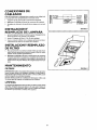
INSTALACION
Y
REEMPLAZO DE LAMPARA
I.
Apriete los lados del difusor de luz hasta que se desenganchen
aletas del difusor de las ranuras err la campana.
2.
lnstalc (2) l_mparas
3-
Vuelva a colocar el difusor en la campana
apretando
enganchando
las aletas en las ranuras de la campana.
deTipoA-15
INSTALACION
DE FILTRO
NEGRO
i
•
i
i TORNILL0
VERDE
: DEC
ON
:
•: ..............
del cableado.
y asegure
BLANCO
:
NEGRO
VERDE 0
EX,'UESTO
(A TIERRA)
FIGURA
8
FIGURA
9
las
de 40 vatios m_Lximo.
los iados y
Y REEMPLAZO
1.
Para una operaci6n
con conducto
instale el ffltro de malla de aluminio. Para una operaci6o
sin conducto,instale
el Eltro de carl_n
(Mod¢in 50190, vendido separadamente).
2.
Reii_rase
a la FIGUR& 9- El ffltro se desliza
dentro
de correderas
en la parte posterior
de la campana,en
cualquiera
de los lados de!
compartimiento
del ventflador, y calza debaio de los broches del
resorte cerca de la parte deiantera
del compartimiento
del venUlador.
HANTENIHIENTO
FILTROS
IMPORTANTE: El fdtro de aluminio debe extraerse
una vez por rues y
lavarse en agua ealicnte con detergente.
Enjuague
en agua limpia, tibia y sacuda el agua sobrante antes de volver a coincar. El filtro puede
tambi_n limpiarse eo su lavadora de platos.
EN UNA INSTALACION
SIN CONDIJCTO:
3-6 meses segfin se requiera, en instalacinnes
Reemplace
el filtro cada
sin conducto.
LIHPIEZA
La campana debe limpiarse de tanto en tanto,por dentro y fuera, usando
agua tibia, detergente
suave para platos y un trapo suave. Nunca use
polvos abrasivos,almohadillas
de lana de acero ni ning_n otro limpiador abrasivo que destruir_ el acabado de la campana.
13
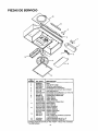
PIEZAS DE SERVICIO
16
12
11
13
NO.
CODIGO
3
4
5
7
8
9
11
12
13
15
16
NO. PIEZA
99080532
R99020277
R99420635
99271236
NTK3720-000
R561138
NTK4402-000
97015294
98009816
RK7694-000
RK7693-000
RK7692-000
NTK6630-000
NTK7474-O00
NTK7472-000
NTK7473-000
NTK7540-000
NTK7539-000
NTK7541-000
R401606
99010316
99010317
97005544
R680508
DESCRIPCION
Motor
Aspa det ver.dador
Pemo Su}r.ador Extemo
Portalamparas (2 requeridos)
EnsambJadode interruptorder ventilador
Interruptorpara luz
Ensambiado del rectificador(Luz nocturna_
Ensamblado del lente de luz
Cubierta para el alambrado
Rejilla (Negra)
Rejiila (Blanca)
Rejilla (Almendra)
Contratuerca (4 requeridas)
Boron (Negra)
Boton (Blanca)
Boron (Almendra)
Deflector (Negra)
Deflector (Blanca)
Deflector (Almendra)
Deflector (Beige)
FiRro, aluminio
Filtro, carbbn sin conductos (comprado
separademente)
Pieza de transicionde 3¼" x 10"
Pieza de transicion ronde de 7"
Encargue piezas de servicio por "NO. PIEZA" - NO por =NO. CODIGO':
* No est_lilustrado.
14
GARANTIA
GARANTIA LIMITADA
Si dentro de 1 aSo de la fecha de la instalaciSn, cualquier parle de esta campana de cocina deja
de funcionar en forma apropiada debido a defecto en el material o la mano de obra, Sears reparar&
la pieza afeetada o proveera e instalard una pieza nueva libre de cargo.
GARANTIA COMPLETA DE 30 DiAS EN EL ACABADO EN PIEZAS MET._LICAS PINTADAS O
ABRILLANTADAS
Si dentro de 30 dias de la fecha de la instalaci6n, el acabado de cualquier parte met&lica pintada
o abrillantada perteneciente a esta campana de cocina aparece con defecto en el material o la
mano de obra, Sears proveer_ e instalard una pieza nueva libre de cargo.
EL SERVICIO DE GARANTIA SE OBTIENE PONII_NDOSE EN CONTACTO CON EL CENTRO
DE SERVICIO O DEPARTAMENTO SEARS M,_S CERCANO EN LOS ESTADOS UNIDOS.
Esta garantia es valedera unicamente si este producto se tiene en uso dentro de los Estados
Unidos. Esta garantia le confiere derechos legales especfficos y Ud. puede tener adem&s otros
derechos que varian de estado a estado.
Sears, Roebuck and Co., Dept. 817_,_A, Hoffman Estates, IL 60179
15
SH/ARS
MANUAL
DEL DUEI_IO
ModelosNos.
233.52052002
233.52053002
233.52057002
233.52059002
233.52 52002
233.52 53002
233.52 57002
233.52 59002
CAMPANA
DE COCINA
Sears se complace
en ofrecer
a sus
cllentes
servicio
de reparaci6n
de aparatos
electrodom(_sticos
y
electr6nicos
de todas
las marcas.
En Sears,
usted puede
contar con
operadores
en espafiol,
a los
que puede
ilamar sin cargo alguno.
,_J__T*Ta
kTAT*TA_V
JA_VJ
Ja_V_
Para pedir serviclo de reparaci6n
a domicilio,
El n_mero clel modelo de
su campana de cocina se Io
encuentra en la etiqueta
dentro de la campana.
Cuando pida servicio
u ordene partes, siempre
d_ la siguiente informaci6n:
t
•
•
Tipo de Producto
N_mero del Moclelo
Nt_mero de la Parte
•
Descripci6n
Parte
24 horas
al dia,
7 dias
a la semana
I 800-676.-5811
Para
ordenar
pleza$
con
a domicllio,
entrega
Liame de 7 am a 7 pro, 7 alias a la semana
1 800-659-7084
de la
Sears, Roebuck
Impreso en los EE. UU.
626875
Ltame
and Co., Hoffman
Estates,
IL 60179
U.S.A.
99043037A