1
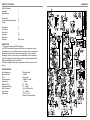
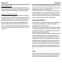
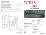
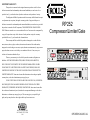
LIMITED WARRANTY
This product is warranted to the original consumer purchaser to be free from
defects in materials and workmanship under normal installation, use and service for a
period of one (1) year from the date of purchase as shown on the purchaser’s receipt.
The obligation of Rolls Corporation under this warranty shall be limited to repair
or replacement (at our option), during the warranty period of any part which proves
RP252
defective in material or workmanship under normal installation, use and service, provided
the product is returned to Rolls Corporation, TRANSPORTATION CHARGES PRE-
Compressor/Limiter/Gate
PAID. Products returned to us or to an authorized Service Center must be accompanied by
a copy of the purchase receipt. In the absence of such purchase receipt, the warranty
period shall be one (1) year from the date of manufacture.
This warranty shall be invalid if the product is damaged as a result of defacement, misuse, abuse, neglect, accident, destruction or alteration of the serial number,
improper electrical voltages or currents, repair, alteration or maintenance by any person or
GAIN REDUCTION
party other than our own service facility or an authorized Service Center, or any use
1
violative of instructions furnished by us.
2
-12
-18
4
6
4:1
-6
8
ACTIVE
GATE
10 12 18 24 38
2.5
7:1
9:1
2
-18
+10
4
6
RATIO
-12
0
0
-24
1
STEREO
0
4:1
-6
7:1
0
-24
+4
This one-year warranty is in lieu of all expressed warranties, obligations or
-30
-30
-40 dB +10
THRESHOLD
liabilities. ANY IMPLIED WARRANTIES, OBLIGATIONS, OR LIABILITIES,
:1
2:1
RATIO
10 mS
1
5 Sec .5
-10 dB +20
ATTACK
RELEASE
LEVEL
-30 dB off
GATE THRESH
slow
fast
GATE REL
-40 dB +10
2:1
THRESHOLD
INCLUDING BUT NOT LIMITED TO THE IMPLIED WARRANTIES OF MERCHANTABILITY AND FITNESS FOR A PARTICULAR PURPOSE, SHALL BE
LIMITED IN DURATION TO THE ONE YEAR DURATION OF THIS WRITTEN
GAIN REDUCTION
ACTIVE
GATE
PWR
6
8
10 12 18 24 38
TIO
2.5
7:1
LIMITED WARRANTY. Some states do not allow limitations on how long an implied
9:1
warranty lasts, so the above limitation may not apply to you.
:1 10 mS
0
COMPRESSOR/LIMITER
GATE
0
+10
+4
1
5 Sec .5
-10 dB +20
ATTACK
RELEASE
LEVEL
-30 dB off
GATE THRESH
slow
fast
GATE REL
RP252
IN NO EVENT SHALL WE BE LIABLE FOR ANY SPECIAL, INCIDENTAL
OR CONSEQUENTIAL DAMAGES FOR BREACH OF THIS OR ANY OTHER
WARRANTY, EXPRESSED OR IMPLIED, WHATSOEVER. Some states do not allow
the exclusion or limitation of special, incidental or consequential damages so the above
limitation or exclusion may not apply to you. This warranty gives you specific legal
rights, and you may also have other rights which vary from state to state.
ROLLS CORPORATION
SALT LAKE CITY, UTAH
11/01
OWNERS MANUAL
2
3
2
STEREO/MONO
J4
XLR F PC
3
J2
XLR F PC
J3
PHONE 1/4
1
2
1
4
5
6
120PF
C201
-V
U6A
E3
E2
E1
7
SW5B
4PDT
R246
10K
1
1
D4
1N4001
D3
D2
U11A
-V
-V
RELEASE
P4
500K
2
1
100K
RATIO
P13
1 N 4 1 4 87
D 3 7
C2
U18
7912
I
I
7812
U17
C214
10UF
O
O
Q2
D8
R141 10K
R140 10K
4560
U5B
3
3
C10K
P5
-V
+V
P6
100K
C4
47U
C3
1U
RATIO
+V
2N3904
U10B
4.7K
R1
R156
1K
1N751
CR1
LM358
R138
1
10K
D7
1N4148
R238
1
10K
7
4560
C212
27PF
U10A
D10, D11, D12, D13, D14
U13 BA6125
C6
503
2K
X5
R150 R152 R154
+V
R151 R153
-V
3
2
U14 BA6125
R164
10K D15, D16, D17, D18, D19
R163
10K
R157
10K
2K
X5
R158 R160 R162
+V
R159 R161
C211
1U
R6
+V
50K TP
OFFSET
R122
10
R121
220K LM13600
14
U3B
13
R247
22K
R222
10
6
5
3
2
+V
4560
R248 18K
C217 503
U12B
+V
D 3 9
1 N 7 5 1 A
R224 3
6.8K
U9A
R256
1K
R255
4.7K
7
-V
CR2
1N751
2
R127
3
R263
10K
18K
R228
J11
PHONE 1/4
R249
10K
D20, D21, D22, D23, D24
U15 BA6125
5
6
C7
503
+V
R264
4
-V
DPDT
SW1B
D33
LDRG
DPDT
R46
4.7K
3
7
R257
10K
U16 BA6125
2K
X5
2
-V
R2
3
SW3B
DPDT
5
DPDT
SW2B
6
6
5
R134
470
3
5
5
+V
U6B
+V
U1B
5968 South 350 West
Salt Lake City, UT 84107
Date: 14 October 2001
Document Number:
Rb RP252.SCH
7
7
Rev:
E
Sheet 1 of 1
COMPRESSOR / LIMITER / GATE RP252
4560
4560
J10
XLR JACK M
J6
XLR JACK M
OUT
J5 PHONE 1/4
J9
PHONE 1/4
6
4
D32
LDRR
Q4
J113
-V
R234
470
Q10
J113
+V
I/0 DPDT X4
SW4C
ROLLS CORPORATION
6
4
1U
R132
4.7K
R133
470
R7
1M
D34
LDRR
R231
470
-V
R3
4.7K
5
R232
4.7K
D25, D26, D27, D28, D29 Size:
10K
2K
C210
10U
R233
SW5C
4PDT
9
8
7
1M
R235
470
R131
C110
10U
2
CR3
1N4148
DPDT
SW2A
R135
1M
BYPASS
SW3A
1
7
3
1
R260
R258
R259R261
R262
4560
X5
+V
U9B
47K
27PF
R230
C209
4560
47K
U4B
+V
SIDE CHAIN
J8
PHONE 1/4
4.7K
C109
27PF
R130
J7
PHONE 1/4
5
6
J12
PHONE 1/4
R227
3
1N4148
23
Q9
J113
R128
4.7K
R229
OUTPUT TRIM
P100K
4.7K
P3
D9
23
Q3
J113
1N4148
D6
OUTPUT TRIM
R129
P100K
4.7K
R250 R252 R254
+V
R251
R253
C208
1U
R226
51
1
4560
C9
.001
C207 120PF
22K
4.7K
R225
R8
R126
51
2
-V
C8
.001
C107
120PF C108
1U
4560
2
1
22K
4.7K
R125
R9
9
10
R223
47K
D 4 0
1 N 7 5 1 A
R124
6.8K
9
10
R123
47K
+V
-V
R221 LM13600
LM13600 220K
14
8
U8A
U8B
7
13
+V
C12 470PF
R220
R219
4.7K 10K
R236
22K
C13
470PF
R218
22K
4
3
-V
OFFSET
R5
+V
50K TP
LM13600
8
U3A
7
+V
R119 R120
4.7K 10K
C111
1U
C206
503
LDRR
R217
1M
R216
C11
THRESHOLD
.001
R237
P7 500K
47K
D35
1N4148
U7B
-V
3
2
+V
GATE CLOSED
+V R215
220K
LM358
R239 10K
6
R214
47K
U5A
4560
C112
27PF
4
3
R118
22K
R136
22K
C106
503
C10
THRESHOLD .001
500K
R137 47K P14
7
R117
1M
R116 D31
10K
LDRR
GATE CLOSED +V
R115
220K
U2B
R155
4.7K R149
10K
D36
5
1N4148
6
R241 10K
R240
10K
4560
-V
+V
47K
R114
R139 10K
5
1N4148
6
-V
6
C105
10U
5
P8
P100K
RELEASE
+V
POWER
C5 LDSG
503
D5
-V
R211
22K
D 3 8
ATTACK 1 N 4 1 4 8
7
LM358
R243
2
100
3
-V
C1
R244 100K
4560
U12A
R205
10K
R206
1K 3
2
C202
1U
R208
C10K
P12
ATTACK
100K
-V
503
R111
22K
R110
1
Q1
2N3904
C104 2N3904
-V
10K
R112
+V
C203 120PF 33K
R212 RELEASE
R209
P1
10K
2K
P100K
R207
Q7
2N3904
100K
-V C204
R210
C205
Q8
10U
1100K
U7A
5
503
100
2R143
3
-V
LM358
U2A
R107
100K
R109
2K
+V
7
8
9
R108
C103 120PF 33K
R144 100K
P11
C114
10UF
4560
1N4001
1N4001
D1
1N4001
R148
18K
U11B
4560
4
5
6
-V
1
R105
10K
R106
1K 3
+4/-10 P2
P100K
4560
100K
R204
1
2
C102
1U
+4/-10 P9
P100K
RELEASE
500K
4560
R104
100K
4PDT
SW5A
C117 .047
6
+V
R245
100K
3
2
U1A
SW4B
4PDT
R146
10K
3
2
R203
10K
5
R147 22K
SW1A
DPDT
R202
10K
R201
10K
R145
100K
R102
10K
C101
27PF
1
2
3
4
1
2
3
4
R101
10K
8
4
4
4
IN
1
4
2 2 0 0 U F 1 6 V2 2 0 0 U F 1 6 V
8
8
8
4
11
11
15
4PDT
R103 SW4A
10K
G
2
1
G
8
1
5
9
8
7
6
5
4
3
2
1
4
9
8
7
6
5
4
3
2
1
2
1
5
2
6
16
12
15
6
16
12
8
J1
PHONE 1/4
9
8
7
6
5
4
3
2
1
8
8
2
1
2
1
1
10k9 balanced
+21 dBu
.05% typical
-40dBu to +10dBu
1 - 10ms.
0.5 - 5 Sec.
2:1 - infinity:1
-30 to +4 dB, and Off.
-10 - +20dB
1.75" x 6" x 19"
(44mm x 152mm 483mm)
8
SPECIFICATIONS
Input Impedance:
Max Input Level:
THD:
Threshold range:
Attack Time:
Release Time:
Compression Ratio:
Gate Threshold:
Output Gain:
Dimensions:
8
INSPECTION
1. Unpack and Inspect the RP252 package
Your RP252 was carefully packed at the factory in a protective carton.
Nonetheless, be sure to examine the unit and the carton for any signs of
damage that may have occurred during shipping. If obvious physical
damage is noticed, contact the carrier immediately to make a damage
claim. We suggest saving the shipping carton and packing materials for
safely transporting the unit in the future.
2. Please complete the Warranty Registration Card and return it to the
factory.
4
3
3
4
4-5
6
Back Cover
4
Description
Front Panel
Rear Panel
Operation
Schematic
Warranty
1
2
2
2
1
Introduction
Understanding Compression
Gating
1
1
1
1
1
Table of Contents
Inspection
Specifications
9
8
7
6
5
4
3
2
1
TABLE OF CONTENTS
SCHEMATIC
6
3
OPERATION CONT
Raising the Signal Out of a Mix
Since reducing dynamic range can increase the average signal level and meter
readings, a single track can be brought up out of a mix by boosting its level slightly
and applying compression. Set the Threshold for 4 dB to 6 dB of compression.
Preventing Sound System Overload (Limiting)
Applications where an abolute maximum signal level must be set to avoid distortion or speaker damage, set the RP252 for Limiting. Limiting has been defined as
a signal-to-compression ratio of 10:1 or more. Start with the Ratio at infinity:1, use
a fast Attack and set the Threshold at 15 dB of compression or just a few dB
below the clipping point of the sound system. At low levels the RP252 won’t do
anything, but at higher levels the peaks will be limited to the Threshold point.
Often, it is recommended the compressor/limiter be inserted just before the power
amp, some systems even have a separate compressor/limiter on each output of
the crossover.
INTRODUCTION
Thank you for choosing the ROLLS RP252 Compressor/Limiter/Gate. We recommend you take a moment and read through this manual as it provides information
that will assist you in using your unit to it’s fullest potential.
The RP252 provides clear sonic quality and performance for the working musician, DJ, studio operator, or anyone needing a friendly Compressor/ Limiter/Gate.
The RP252 incorporates “soft-knee” compression and a 100 dB log averaging
detector for amazing accuracy and smooth performance. The input connectors on
the rear are designed to be used with -10 dB to +4 dB signal levels.
UNDERSTANDING COMPRESSION
The primary purpose of a compressor is to reduce and control the dynamic range
of a program; from gentle narrowing of overall levels to limiting of peaks, to
squashing all dynamics. Control is the main idea.
Another major use for compressors is to add punch to sloppy sounds. A compressor can do this by making the level of an instrument or a sound more consistent,
or by reducing the volume of the more sustained sections of a note, which comparatively accentuates the leading edge (Attack).
Sustain of instruments, especially guitars and bass can be achieved by raising the
volume of low-level trailing edges of a note, which gives solid presence to the
instrument. It also makes the note-by-note volume more even. All this is done by
changing the gain in response to the signal. When the input is low in level, the
compressor gain remains fixed, usually at 0 dB (unity gain) or greater. When the
input increases above the threshold set by the compressor, the gain begins to
decrease (i.e., the amount of gain reduction increases). For very large inputs, the
gain can decrease considerably, Therefore, as signals get larger, the gain reduction will increase, depending where the Threshold, Ratio and Output Level are
set.
GATING
Gating is used to cut noise or “hiss” when there is no signal, or when the signal is
below a certain threshold. Sometimes, such as with drums, the gate is used to
stop all sound except when the drum is played, to remove background noise.
5
2
DESCRIPTION CONT.
DESCRIPTION
REAR PANEL
NOTE: Descriptions are identical for both Channels One and Two
FRONT PANEL
NOTE: Descriptions are identical for both Channels One and Two
GAIN REDUCTION
ACTIVE
GAIN REDUCTION
GATE
ACTIVE
2
-18
4
6
4:1
-6
8
10 12 18 24 38
2.5
7:1
9:1
2
-18
+10
4
6
8
10 12 18 24 38
RATIO
-12
0
0
-24
1
STEREO
0
4:1
-6
2.5
7:1
0
9:1
COMPRESSOR/LIMITER
GATE
0
+10
0
-24
+4
+4
-30
-30
-40 dB +10
THRESHOLD
2:1
RATIO
:1
10 mS
1
5 Sec .5
-10 dB +20
ATTACK
RELEASE
LEVEL
-30 dB off
GATE THRESH
fast
slow
GATE REL
-40 dB +10
THRESHOLD
2:1
:1 10 mS
1
5 Sec .5
-10 dB +20
ATTACK
RELEASE
LEVEL
-30 dB off
GATE THRESH
slow
fast
GATE REL
RP252
THRESHOLD: Sets the level at which the RP252 becomes active. When the
signal level is below the threshold point, the signal is unprocessed. When the
signal level is above the threshold point, there may be compression/limiting.
RATIO: This sets the ratio of input signal to signal compression. Called ‘signal-tocompression ratio, at 1:1 the signal is left unprocessed and at infinity:1, no matter
how much the input increases, the output will not be above the threshold - this is
called limiting.
ATTACK: Adjusts how fast the control circuits respond to the dynamics of the
input. If this is set longer, it will take more time for gain reduction to occur, so
rapidly rising inputs will go through for a short period of time.
RELEASE: Adjusts how long before the control circuits return to a steady state. A
short release time can make sound be choppy and gated. A long release time can
make music seem to rise and fall as a wave. It is recommended to start with a
long Release time, then shorten it if necessary.
OUTPUT LEVEL: Sets the output level to help compensate for compression
losses. If the Threshold is set low, more output level may be needed because gain
reduction starts at a low level.
GATE THRESHOLD: Included in the RP252 is a noise gate circuit which is
accessed with the two gate controls. The Gate Threshold sets the point at which
the gate “opens” to let the sound through. Below this level, the entire signal is shut
off. When the GATE LED is off there is enough level to operate the gate.
GATE RELEASE: As before, this adjusts how long until the gate closes or stops
sound after the signal has fallen below the threshold.
ACTIVE SWITCH: Pressing this switch inward activates the compressor.
STEREO SWITCH: This switch joins the control circuits of the two channels so
they operate together. When processing a stereo signal, this helps maintain a
more natural sound because both sides are processed exactly the same.
GAIN REDUCTION LEDs: These 10 LEDs display, in dB, how much the signal is
being compressed (i.e., how much gain reduction).
GATE LED: When this is lit, no signal passes through the processing circuits and
the sound is muted.
3
CHANNEL 2
MODEL RP252
SERIAL NUMBER
GATE
PWR
1
-12
SIDE CHAIN
CHANNEL 1
OUTPUT
INPUT
SIDE CHAIN
INPUT
OUTPUT
252C
OUTPUT
120 VAC
50/60 Hz 15 VA
MADE IN U.S.A.
WARNING: To reduce the
risk of electric shock or fire,
do not expose this device to
rain or moisture. :
CAUTION: To reduce the risk
US
INPUT
INST
LINE
OUTPUT
INPUT
INST
LINE
of electric shock do not remove
lid. No user serviceable parts
inside. Refer servicing to
qualified service personnel.
RISQUE DE CHOC - NE PAS ENLEVER
INPUT: Use mono (or TRS) 1/4" phone connectors or balanced XLR inputs from
your line-level audio source.
OUTPUT: Use mono (or TRS) 1/4" phone connectors or balanced XLR to connect
to the line inputs on the next device (i.e., mixer, recording device, amplifier, etc.)
SIDE CHAIN: The side chain ins/outs are 1/4" unbalanced jacks used for controlling the gain reduction circuits with an external signal. This is for special effects
such as “ducking”.
INST/LINE SWITCH: This switch changes the RP252 dynamic range by 20 dB. In
for instrument level, out for line level signals.
OPERATION
Smoothing Out Electric Bass
Bass lines often are inconsistent in level and lack the sustain needed to give a
solid bottom end. Set the Threshold so that peaks cause 10 dB to 12 dB of
compression. Use more for increased sustain and for more percussive attacks on
the trainsients.
Fattening Kick Drums and Compressing Other Drum Sounds
Weak, flabby kick drums often have too much boom and not enough slap. Tighen
them up by increasing the Attack time and setting the threshold for 15 dB of
compression on the peak of the kick. Because the RP252 takes time to react, this
will emphasize the slap at the beginning of the note and reduce the boominess of
its body. The RP252 also works well for tightening snare drums and tom toms and
can be used with drum machines to effectively alter the character of any electronic drum sound.
Variations in Mic Levels
In musical applications, paging systems, churches, speaking events, etc., as the
distance between the microphone and the speaker or the vocalist changes, signal
levels change. To keep the level near constant, set the threshold and ratio so an
average of 6 - 8 dB of compression is established.
4