1
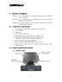
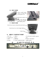
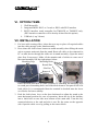
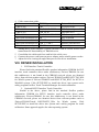
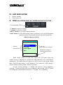
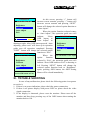
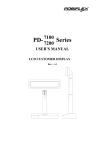
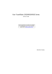
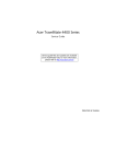
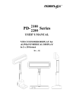
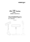
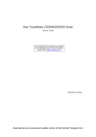
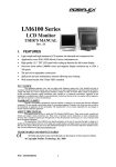
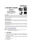
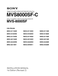
TM4000 Series Touch Monitor USER’S MANUAL Rev. : A I. • • • • • • • • • • FEATURES Most stable touch monitor for industrial and commercial use Application covers POS, POI (Kiosk), -Factory Automation etc. High quality 12.1”/15” TFT LCD panel with scaling function for full screen display Resistive type extra long life touch panel with touch resolution 1024 x 1024 Recommended. LCD resolution: 800 x 600 for 12.1” and 1024 x 768 for 15” 1 up 3 down USB Hub (option), relay PS/2 keyboard & PS/2 mouse connectors Tilt and height adjustable yet robust and wobble free construction Spill proof and easy maintenance structure allowing easy cleaning Touch functions include left/right button, double click, drag & drop Touch beep can be pitch adjusted and enabled/disabled by software control FCC NOTICE This equipment generates, uses, and can radiate radio frequency energy and, if not installed and used in accordance with the instructions manual, may cause interference to radio communications. It has been tested and found to comply with limits for a Class A digital device pursuant to subpart J of Part 15 of FCC Rules, which are designed to provide reasonable protection against interference when operated in a commercial environment. Operation of this equipment in a residential area is likely to cause interference in which case the user at his own expense will be required to take whatever measures to correct the interference. WARRANTY LIMITS Warranty will terminate automatically when the machine is opened by any person other than the authorized technicians. The user should consult his/her dealer for the problem happened. Warranty voids if the user does not follow the instructions in application of this merchandise. The manufacturer is by no means responsible for any damage or hazard caused by improper application. ABOUT THIS MANUAL This manual assists the user to utilize the TOUCH Monitor TM4000 series. These series provide versatile font formats and support various instruction sets. These series of products receive instructions in serial communication protocols and is capable of entering pass through mode so that all instructions received pass on to next connected serial device if properly configured. The manufacturer of the TM4000 series heartily apologizes to the user for reserving the right to change or to modify this manual without notice due to the rapid and constant progress and improvement on science and technology. The user may always obtain the most up to date information through any of our web sites: http://www.posiflex.com.tw, http: //www.posiflexuk.com, http://www.posiflexusa.com. Copyright Mustek Corp. 2001 TRADE MARKS AND SERVICE MARKS POSIFLEX is a registered trademark of Mustek Corp.. Other brand and product names are trademarks and registered trademarks and service marks of their respective owners. CMANUTM4000-1 1 II. MODEL NUMBER TM4012: 12.1” LCD Monitor w/ standard touch panel and PS/2 interface touch controller TM4012E: 12.1” LCD Monitor w/ extra durable touch panel and PS/2 interface touch controller TM4015E: 15” LCD Monitor w/ extra durable touch panel and PS/2 interface touch controller III. CARTON CONTENTS 1. 2. 3. 4. 5. 6. 7. 8. 9. 10. Touch Monitor (Main unit + Adjustable stand assembly) User’s Manual Plastic key VGA cable: CCBLA-366 PS/2 KB cable w/ purple connectors: CCBLA-367 PS/2 Mouse cable w/ green connectors: CCBLA-384 USB cable: CCBLA-383 (for optional USB hub) Posiflex Product Information CDROM Power adaptor: ASP0P042WTB001 & power cord RS232 cable: CCBLA-368 (for optional RS232 interface touch controller only) IV. PARTS IDENTIFICATION A. FRONT VIEW Display Screen + Touch Panel Main Unit Adjustable Stand Assembly MSR Unit (option) 2 B. SIDE VIEWS Power on/off switch (Press on white dot to turn power on) Latch hole for cable cover Lock/release lever Push in this direction to adjust the tilt angle of the display panel C. REAR VIEW Lock/release button to detach the main unit Lock/release lever for tilt angle adjust Cable Exit V. INPUT / OUTPUT PORT a. DC 12V b. USB TO PC c. CRT d. USB 3 a e. USB 2 f. USB 1 g. MOUSE h. TO (PC) MOUSE PORT b c d e f 3 i. TO (PC) RS232 PORT (option) j. KB k. TO (PC) KB PORT l. MSR (option) g h i j k l VI. OPTION ITEMS 1. Wall Mount Kit 2. Integrated MSR: ISO 2 or 3 track or JIS II with PS/2 interface 3. RS232 interface touch controller for TM4012E or TM4015E only. (PS/2 interface controller will be hereby deleted for this option) 4. USB hub (1 up 3 down) VII. INSTALLATION 1. For best cable routing effect, please do next step to place all required cables into the cable passage in the stand assembly. 2. Press down the lock/release button on stand assembly when lifting the main unit to separate main unit from the stand. Route all cables to be connected to PC or other device through the cable exit in stand assembly. (Open the metal plate first if necessary.) Make all the monitor end of cables to come out of the stand assembly like the right picture below. Matching Pegs Matching Holes Round Part Slot Part Removal Hollow Hook the main unit back on stand assembly by matching the matching pegs to round part of matching holes and slide them down to slot part till the rear latch clicks. It is recommended that the terminal be hooked onto the lower set of holes for better stability. 3. Push the lock/release lever on the base backward to adjust the stand to the most horizontal position for ease of operation. Insert the tip of the latchkey into a latch hole on one side near bottom of the main unit. Turn this key counterclockwise to the end and take it out. Do the same on the opposite side. Open the cable cover by pulling at the removal hole. 4 4. Cable connection guide: Cable TM4000 port External device CCBLA-366 CRT VGA port of PC CCBLA-367 TO (PC) KB PORT PS/2 keyboard port of PC CCBLA-383 USB TO PC USB port of PC CCBLA-384 TO (PC) MOUSE PORT PS/2 mouse port of PC Cable from external device KB PS/2 keyboard Cable from external device MOUSE PS/2 mouse Cable from external device USB 1 ~ USB 3 External USB devices Cable from power adaptor DC 12V Power adaptor Among these, power adaptor, CCBLA-366 and CCBLA-384 are crucial vital connections for functionality of TM4000 series. 5. Consolidate the cables and close and lock the cable cover. 6. Connect the power cord between power adaptor and a suitable power socket. 7. Adjust for best viewing tilt angle then proceed for driver installation. VIII. DRIVER INSTALLATION 1. PS/2 Interface Touch Controller: Please find in the attached Posiflex product information CDROM for PS/2 interface touch controller driver under subdirectory \Drivers\TM4000. In case this subdirectory is not found in the CDROM received, please use identical driver from relevant product such as \Drivers\TP6000\Touch\PS-II\TCTM_W98 for Win98 system or \Drivers\TP6000\Touch\PS-II\TCTM_WNT for NT4.0 or Win2000 system. Click SETUP.EXE to install the driver into system and a utility program Posiflex Touch Terminal Manager for touch calibration. 2. Optional RS232 Interface Touch Controller: Similar to the above, please find in the attached Posiflex product information CDROM for RS232 interface touch controller driver under subdirectory \Drivers\TM4000. In case this subdirectory is not found in the CDROM received, please use identical driver from relevant product such as \Drivers\TP6000\Touch\ RS232\RSTC_W9x for Win9x system. Click SETUP.EXE to install the driver into system and a utility program for touch calibration. Same approach applies for other operating system. 5 IX. LED INDICATION • • Orange: standby Green: power on X. OSD (ON SCREEN DISPLAY) SCREEN ADJUST FUNCTION Power/Standby LED “+” button: to increase setting. “-” button: to decrease setting. “NEXT” button: to go to next option function. “OSD” button: to enter OSD setting menu or submenu, or to execute designated operation shown in operation shown in operation guide area. OSD description as below: POSIFLEX OSD Setting Menu Option function list Brightness Contrast Auto Adjust Exit Option function selected Parameter setting or Operation guide area Press “OSD” button on front bezel below the LCD panel when any normal screen is displayed to activate the OSD functions (on screen display adjustment). The main menu will pop up on LCD screen in the layout shown above. In OSD main menu, it will disappear if no button for OSD setting is pressed within a period of time (about 30 seconds). At this screen, pressing “+” button will increase screen brightness, pressing “-” button will decrease screen brightness and pressing “NEXT” button will change the selected option function to “Contrast” as next drawing. 6 At this screen, pressing “+” button will increase screen contrast, pressing “-” button will OSD Setting Menu decrease screen contrast and pressing “NEXT” Brightness button will change the selected option function to Contrast “Auto Aujust”. Auto Adjust When the option function selected comes Exit to “Auto Adjust”, the operation guide area will indicate “Press POSIFLEX OSD button to OSD Setting Menu Auto Adjust” as Brightness drawing at right. After OSD button pressed, “Auto Contrast adjusting, please wait” will show up in operation Auto Adjust guide area till operation completed. Pressing Exit “NEXT” button will change the selected option function to “Exit”. POSIFLEX When the Press OSD button to Auto Adjust OSD Setting Menu option function Brightness selected is “Exit”, the operation guide area will Contrast indicate “Press OSD button to Exit” as drawing at Auto Adjust left. Pressing “NEXT” button will change the Exit selected option function back to “Brightness” again, pressing OSD button, the OSD Setting Menu will be closed immediately. Press OSD button to Exit POSIFLEX XI. TROUBLE SHOOTING In case of any malfunction, please check the following points in sequence to resolve it. 1. If there is no power indication, please check the power connection. 2. If there is no picture display with power LED on, please check the video signal connection. 3. If the display is abnormal, please reset the monitor: Please turn off the monitor and then keep pressing any of the OSD button when turning the monitor back to ON. 7 4. If there is no touch function, please check the connection of the PS/2 Mouse cable with green connectors (CCBLA-384) or the RS232 cable (CCBLA368) for optional RS232 interface touch controller. Please pay particular attention on whether the PS/2 Mouse cable is connected to the right connector on TM4000 series or whether the RS232 cable is connected to the right COM port of PC according to the driver installation. 5. The USB hub function could be disrupted if any current overload of the down stream USB device occurs. Please turn off the TM4000 series and turn it back on to reinstate the USB hub. If problem still presents, please disconnect the down stream USB device and check the current loading of that USB device. 8