1
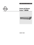
INSTALLATION/OPERATION
TXB-AD
Translator Board
C1492M-I (8/05)
Contents
Regulatory Notices . . . . . . . . . . . . . . . . . . . . . . . . . . . . . . . . . . . . . . . . . . . . . . . . . . . . . . . . . . . . . . . . 3
Important Notice . . . . . . . . . . . . . . . . . . . . . . . . . . . . . . . . . . . . . . . . . . . . . . . . . . . . . . . . . . . . . . . . . 4
Description . . . . . . . . . . . . . . . . . . . . . . . . . . . . . . . . . . . . . . . . . . . . . . . . . . . . . . . . . . . . . . . . . . . . . . 5
Esprit Integrated Positioning System Installation . . . . . . . . . . . . . . . . . . . . . . . . . . . . . . . . . . . . . . . . 6
TXB-AD Translator Board Installation and Settings . . . . . . . . . . . . . . . . . . . . . . . . . . . . . . . . . 6
Esprit System Settings and Connections . . . . . . . . . . . . . . . . . . . . . . . . . . . . . . . . . . . . . . . . . . 8
Spectra Dome Installation . . . . . . . . . . . . . . . . . . . . . . . . . . . . . . . . . . . . . . . . . . . . . . . . . . . . . . . . . 10
TXB-AD Translator Board Installation and Settings . . . . . . . . . . . . . . . . . . . . . . . . . . . . . . . . 10
Spectra System Settings and Connections . . . . . . . . . . . . . . . . . . . . . . . . . . . . . . . . . . . . . . . 13
ExSite Explosionproof System Installation . . . . . . . . . . . . . . . . . . . . . . . . . . . . . . . . . . . . . . . . . . . . 14
TXB-AD Translator Board Installation and Settings . . . . . . . . . . . . . . . . . . . . . . . . . . . . . . . . 14
ExSite Explosionproof System Settings . . . . . . . . . . . . . . . . . . . . . . . . . . . . . . . . . . . . . . . . . 17
Operation . . . . . . . . . . . . . . . . . . . . . . . . . . . . . . . . . . . . . . . . . . . . . . . . . . . . . . . . . . . . . . . . . . . . . . 18
Troubleshooting . . . . . . . . . . . . . . . . . . . . . . . . . . . . . . . . . . . . . . . . . . . . . . . . . . . . . . . . . . . . . . . . . 21
Appendix. . . . . . . . . . . . . . . . . . . . . . . . . . . . . . . . . . . . . . . . . . . . . . . . . . . . . . . . . . . . . . . . . . . . . . . 22
List of Illustrations
1
2
3
4
5
6
7
8
9
10
11
12
13
14
15
Esprit System Pan and Tilt . . . . . . . . . . . . . . . . . . . . . . . . . . . . . . . . . . . . . . . . . . . . . . . . . . . . . 6
TXB-AD Translator Board Layout, Front and Back . . . . . . . . . . . . . . . . . . . . . . . . . . . . . . . . . . . 7
Receiver Location . . . . . . . . . . . . . . . . . . . . . . . . . . . . . . . . . . . . . . . . . . . . . . . . . . . . . . . . . . . . 7
Proper Installation of Cover . . . . . . . . . . . . . . . . . . . . . . . . . . . . . . . . . . . . . . . . . . . . . . . . . . . . 8
How to Install Cover . . . . . . . . . . . . . . . . . . . . . . . . . . . . . . . . . . . . . . . . . . . . . . . . . . . . . . . . . . 9
TXB-AD Translator Board Layout, Front and Back . . . . . . . . . . . . . . . . . . . . . . . . . . . . . . . . . . 10
Receiver Location . . . . . . . . . . . . . . . . . . . . . . . . . . . . . . . . . . . . . . . . . . . . . . . . . . . . . . . . . . . 11
Spectra Dome System, Interconnect Door . . . . . . . . . . . . . . . . . . . . . . . . . . . . . . . . . . . . . . . . 12
Spectra Dome System, Circuit Board . . . . . . . . . . . . . . . . . . . . . . . . . . . . . . . . . . . . . . . . . . . . 12
Dome Drive Installation . . . . . . . . . . . . . . . . . . . . . . . . . . . . . . . . . . . . . . . . . . . . . . . . . . . . . . 13
Spanner Wrench . . . . . . . . . . . . . . . . . . . . . . . . . . . . . . . . . . . . . . . . . . . . . . . . . . . . . . . . . . . . 14
Removal of Pan and Tilt Unit . . . . . . . . . . . . . . . . . . . . . . . . . . . . . . . . . . . . . . . . . . . . . . . . . . 14
TXB-AD Translator Board Layout, Front and Back . . . . . . . . . . . . . . . . . . . . . . . . . . . . . . . . . . 15
Receiver Location . . . . . . . . . . . . . . . . . . . . . . . . . . . . . . . . . . . . . . . . . . . . . . . . . . . . . . . . . . . 15
TXB-AD Board Installation . . . . . . . . . . . . . . . . . . . . . . . . . . . . . . . . . . . . . . . . . . . . . . . . . . . . 16
List of Tables
A
B
C
D
2
TXB-AD DIP Switch Settings . . . . . . . . . . . . . . . . . . . . . . . . . . . . . . . . . . . . . . . . . . . . . . . . . .
American Dynamics Camera Assignments. . . . . . . . . . . . . . . . . . . . . . . . . . . . . . . . . . . . . . . .
Switch Settings for SW2 . . . . . . . . . . . . . . . . . . . . . . . . . . . . . . . . . . . . . . . . . . . . . . . . . . . . .
Switch Settings for SW1 . . . . . . . . . . . . . . . . . . . . . . . . . . . . . . . . . . . . . . . . . . . . . . . . . . . . .
22
23
27
29
C1492M-I (8/05)
Regulatory Notices
This device complies with Part 15 of the FCC Rules. Operation is subject to the following two
conditions: (1) this device may not cause harmful interference, and (2) this device must accept any
interference received, including interference that may cause undesired operation.
RADIO AND TELEVISION INTERFERENCE
This equipment has been tested and found to comply with the limits of a Class B digital device,
pursuant to Part 15 of the FCC Rules. These limits are designed to provide reasonable protection
against harmful interference in a residential installation. This equipment generates, uses, and can
radiate radio frequency energy and, if not installed and used in accordance with the instructions, may
cause harmful interference to radio communications. However there is no guarantee that the
interference will not occur in a particular installation. If this equipment does cause harmful
interference to radio or television reception, which can be determined by turning the equipment off
and on, the user is encouraged to try to correct the interference by one or more of the following
measures:
•
Reorient or relocate the receiving antenna.
•
Increase the separation between the equipment and the receiver.
•
Connect the equipment into an outlet on a circuit different from that to which the receiver is
connected.
•
Consult the dealer or an experienced radio/TV technician for help.
You may also find helpful the following booklet, prepared by the FCC: “How to Identify and Resolve
Radio-TV Interference Problems.” This booklet is available from the U.S. Government Printing Office,
Washington D.C. 20402.
Changes and modifications not expressly approved by the manufacturer or registrant of this
equipment can void your authority to operate this equipment under Federal Communications
Commission’s rules.
This Class B digital apparatus complies with Canadian ICES-003.
Cet appareil numérique de la classe B est conforme à la norme NMB-003 du Canada.
C1492M-I (8/05)
3
Important Notice
All companies make changes and improvements in their products on a regular basis. Because this
product is interfacing with equipment not manufactured by Pelco, the possibility exists that the
interface protocols have changed or are in a different configuration from earlier tested units;
therefore, an incompatibility may occur. The existence of prior successful installations indicates our
intent to provide equipment compatible with other manufacturers, but does not guarantee successful
results without on-site integration testing.
Pelco recommends purchasing a single unit for bench testing before the purchase and
installation of this product in quantity. Should any problems occur, Pelco will provide on-site
technical support (North American installations only) to analyze the interface protocols of your
system. We will typically schedule this visit within one week of when the problem is reported to Pelco
Technical Support. Pelco will endeavor, at its expense, to correct the interface incompatibility within
two weeks on a high priority basis. During these visits, the end user must agree to give Pelco
reasonable access to the system in order to study and correct the protocol incompatibility.
In the unlikely event that Pelco is unable to make the translator work in the system, Pelco will accept
the return of any Pelco products associated with the translator and refund the amounts paid for these
products plus freight expenses. Because Pelco recommends a bench test prior to installation, Pelco
will not be liable for any installation costs or lost revenues in the event it cannot solve the
compatibility problem.
4
C1492M-I (8/05)
Description
The TXB-AD translator board allows American Dynamics controllers to communicate with Pelco’s
Esprit®, ExSite™, and Spectra® systems. Once installed the Spectra dome, ExSite, or Esprit system
receives Manchester code commands from the American Dynamics controller and converts the
commands into Pelco’s D protocol.
The TXB-AD has been tested and shown to work with the following American Dynamics systems:
AD168 Matrix Switcher
AD1600 Series
AD1983 Control Code Converter
AD2091 Series
AD2150 Series
Based on the information published by American Dynamics, Pelco has reason to believe the TXB-AD
will also work with the following models:
AD1650 Series
AD2050 Series
AD2350 Series
C1492M-I (8/05)
5
Esprit Integrated Positioning System Installation
The following items are supplied:
1 TXB-AD translator board (printed circuit board)
1 4-40 screw with lock washer (for Spectra II ® Series only)
1 6-32 screw with lock washer (for Spectra III ™ Series only)
TXB-AD TRANSLATOR BOARD INSTALLATION AND SETTINGS
1. Turn off the power to the Esprit system. Refer to Figure 1 and do the following:
a.
Remove the left cover on the pan and tilt.
b.
Remove the shorting plug from the 16-pin connector located on the Esprit system’s
circuit board.
c.
Remove the nut and washer from the standoff on the Esprit system’s circuit board.
NOTE: Do not discard the 16-pin shorting plug. Save the plug in case the system ever is converted
back to a Pelco-controlled unit.
SW2 SW1
ON
OFF 1 2 3 4 5 6 7 8
ON
OFF 1 2 3 4 5 6 7 8
DIP SWITCHES
PHILLIPS
SCREW
NYLON
WASHER
16-PIN
CONNECTER
Figure 1. Esprit System Pan and Tilt
6
C1492M-I (8/05)
2. Set the J1 jumper on the TXB-AD to the proper termination setting. The TXB-AD is shipped
from the factory with the J1 jumper in the terminated position. To unterminate the unit
remove the cover from the J1 jumper and then place the cover over one pin for storage. Refer
to Figure 2 and Figure 3.
16-PIN CONNECTOR
J1 JUMPER
J1 UNTERMINATED
J1 TERMINATED
BACK
FRONT
DIP
SWITCH
Figure 2. TXB-AD Translator Board Layout, Front and Back
EXAMPLE OF STAR CONFIGURATION WITH DAISY CHAIN
AMERICAN DYNAMICS
CONTROLLER
LINE
1
LINE
2
PTZ
LINE
3
PTZ
PTZ
LINE
4
PTZ
LINE
5
PTZ
RECEIVERS
EXAMPLE OF DAISY-CHAIN CONFIGURATION
AMERICAN DYNAMICS
CONTROLLER
LINE
1
PTZ
LINE
2
PTZ
LINE
3
PTZ
LINE
4
PTZ
LINE
5
PTZ
RECEIVERS
PTZ
= TERMINATED
PTZ
= UNTERMINATED
LINES 1-5 MUST NOT TOTAL MORE THAN 4,000 FT (1,219 M)
Figure 3. Receiver Location
3. Set DIP switches on the TXB-AD. Refer to Figure 2 and Table A.
C1492M-I (8/05)
7
4. Install the TXB-AD translator by inserting the 16-pin connector located on the back of the
TXB-AD board into the mating connector on the Esprit system’s board. Refer to Figure 1 and
Figure 2.
5. Reinstall the nut and washer on the standoff to secure the translator board.
ESPRIT SYSTEM SETTINGS AND CONNECTIONS
1. Verify that all SW1 switches on the Esprit system are set to the OFF position.
For American Dynamics controllers with only 32 presets: Set SW1-5 to the ON
position. Refer to Figure 1 for switch location.
2. Set the address for the Esprit positioning system. Refer to Table B and Table C in the Appendix
for American Dynamics Camera Assignments and DIP switch settings. Refer to Figure 1 for
DIP switch location.
3. Reinstall the left cover on the pan and tilt. The cover must be properly seated and have a tight
seal all the way around when installed (refer to Figure 4). To reinstall the cover, do the
following:
a.
Properly position the cover and slide it into place. The sides of the cover must fi t under
the front and back rain guards of the pan and tilt, and the top of the cover must seat
against the lip of the top gasket.
b.
Apply pressure and push the top of the cover down to align the screw holes (refer to
Figure 5).
c.
Insert the Phillips screw and washer. Tighten until the screw will not turn.
NOT SEALED
THIS SIDE IS
PROPERLY
INSTALLED
THIS SIDE IS
IMPROPERLY
INSTALLED
GAP
Figure 4. Proper Installation of Cover
8
C1492M-I (8/05)
TOP GASKET
FRONT
RAIN
GUARD
Figure 5. How to Install Cover
4. Remove the pan and tilt from the base of the Esprit System. Check the control wiring inside
the base of the unit.
From AD Controller
To 4-Wire Cable
B
RX+ (Green wire)
W
RX- (Red wire)
NOTE: To wire the connector for the controller, refer to the manual supplied with the American
Dynamics controller.
5. Reinstall the pan and tilt onto the base of the unit. Apply power to the system. The following
message is displayed on the monitor once the configuration cycle of the Esprit is completed:
TXB-AD Rev x.xx
NOTE: x.xx represents the current firmware revision.
C1492M-I (8/05)
9
Spectra Dome Installation
The following items are supplied:
1 TXB-AD translator board (printed circuit board)
1 4-40 screw with lock washer (for Spectra II Series only)
1 6-32 screw with lock washer (for Spectra III Series only)
TXB-AD TRANSLATOR BOARD INSTALLATION AND SETTINGS
1. Turn off the power to the dome system. Remove the lower dome. Remove the dome drive by
pressing in the blue and red tabs on the sides of the dome drive. Gently rock the dome drive to
release it from the back box.
2. Set the J1 jumper on the TXB-AD to the proper termination setting. The TXB-AD is shipped
from the factory with the J1 jumper in the terminated position. To unterminate the unit
remove the cover from the J1 jumper and then place the cover over one pin for storage. Refer
to Figure 6 and Figure 7.
16-PIN CONNECTOR
J1 JUMPER
J1 UNTERMINATED
J1 TERMINATED
BACK
DIP
SWITCH
FRONT
Figure 6. TXB-AD Translator Board Layout, Front and Back
10
C1492M-I (8/05)
EXAMPLE OF STAR CONFIGURATION WITH DAISY CHAIN
AMERICAN DYNAMICS
CONTROLLER
LINE
1
LINE
2
PTZ
LINE
3
PTZ
PTZ
LINE
4
PTZ
LINE
5
PTZ
RECEIVERS
EXAMPLE OF DAISY-CHAIN CONFIGURATION
AMERICAN DYNAMICS
CONTROLLER
LINE
1
PTZ
LINE
2
PTZ
LINE
3
PTZ
LINE
4
PTZ
LINE
5
PTZ
RECEIVERS
PTZ
= TERMINATED
PTZ
= UNTERMINATED
LINES 1-5 MUST NOT TOTAL MORE THAN 4,000 FT (1,219 M)
Figure 7. Receiver Location
3. Set DIP switches on the TXB-AD. Refer to Figure 6 and Table A.
4. Install the TXB-AD board. Refer to Figure 8 and Figure 9 and do the following:
a.
Open the hinged door to the back box. Push the tab lock towards the wall of the unit and
lift the door open.
b.
Remove the shorting plug from the 16-pin connector located on the Spectra system’s
circuit board.
NOTE: Do not discard the 16-pin shorting plug. Save the plug in case the system is converted back
to a Pelco-controlled unit.
c.
Insert the TXB-AD translator into the 16-pin connector located on the dome system’s
circuit board.
d.
Secure the translator board to the standoff on the interconnect circuit board using the
provided 4-40 (Spectra II) or 6-32 (Spectra III) screw and lock washer.
C1492M-I (8/05)
11
Figure 8. Spectra Dome System, Interconnect Door
TX-
RX+
TX+
TX+ TX- RX+ RX-
VIDEO
RX-
16-PIN
CONNECTOR
1
2
3
ALARMS
4
5
6
RELAYS
GND AUX2
AUX1
AUX2
GND
GND
7
GND
VIDEO
Figure 9. Spectra Dome System, Circuit Board
12
C1492M-I (8/05)
SPECTRA SYSTEM SETTINGS AND CONNECTIONS
1. Check the wiring to the controller.
From AD Controller
To 4-Wire Terminal Block
B
RX+ (Green wire)
W
RX- (Red wire)
NOTE: To wire the connector for the controller, refer to the manual supplied with the American
Dynamics controller.
2. Close the interconnect door.
3. Verify that all SW1 (Spectra II) or SW3 (Spectra III) switches on the dome drive are set to the
OFF position.
For American Dynamics controllers with only 32 presets: Set SW1-2 (Spectra II) or
SW3-1 (Spectra III) to the ON position. Refer to Figure 6 for switch location.
4. Set the address for the Spectra system. Refer to Table B, Table C (Spectra II), or Table D
(Spectra III) in the Appendix for American Dynamics Camera Assignments and DIP switch
settings.
5. Install the dome drive. Line up the blue (A) and
red (B) tabs with the blue (A) and red (B) labels.
When pushing the tabs in, insert one side,
then the other. Continue pushing on the ends
of the tabs until both click into place. Refer to
Figure 11.
NOTE: Refer to the installation manual supplied with the Spectra III dome for instructions on
installing the back box, dome drive, and lower dome.
6. Apply power to the system. The following
message is displayed on the monitor once the
configuration cycle of the Spectra is
completed:
TXB-AD Rev x.xx
NOTE: x.xx represents the current firmware revision.
Figure 10. Dome Drive
Installation
C1492M-I (8/05)
13
ExSite Explosionproof System Installation
The following items are supplied:
1 TXB-AD translator board
1 4-40 screw with lock washer (for Spectra II Series only)
1 6-32 screw with lock washer (for Spectra III Series only)
TXB-AD TRANSLATOR BOARD INSTALLATION AND SETTINGS
WARNING: To reduce the risk of ignition of hazardous atmospheres, disconnect the
equipment from the supply circuit before opening.
1. Turn off the power to the ExSite system.
CAUTION: Total weight of the pan and tilt component is 55 pounds (25 kg). Use caution
when lifting and assembling the pan and tilt component on the power module. It is
recommended that non-slip gloves be worn during installation or removal.
2. Remove the pan and tilt unit from the power module. Refer to Figure 11 and Figure 12 and do
the following:
a.
Loosen the setscrew in the locking ring with a 2 mm Allen wrench.
b.
Loosen the locking ring with a spanner wrench (Pelco part #MF00-1251-121A).
c.
Carefully unscrew the locking ring, and remove the pan and tilt unit from the power
module.
PAN AND
TILT UNIT
LOCKING
RING
Figure 11. Spanner Wrench
POWER
MODULE
Figure 12. Removal of Pan and Tilt Unit
14
C1492M-I (8/05)
3. Set the J1 jumper on the TXB-AD to the proper termination setting. The TXB-AD is shipped
from the factory with the J1 jumper in the terminated position. To unterminate the unit,
remove the cover from the J1 jumper and then place the cover over one pin for storage. Refer
to Figure 13 and Figure 14.
16-PIN CONNECTOR
J1 JUMPER
J1 UNTERMINATED
J1 TERMINATED
BACK
FRONT
DIP
SWITCH
Figure 13. TXB-AD Translator Board Layout, Front and Back
EXAMPLE OF STAR CONFIGURATION WITH DAISY CHAIN
AMERICAN DYNAMICS
CONTROLLER
LINE
1
LINE
2
PTZ
LINE
3
PTZ
PTZ
LINE
4
PTZ
LINE
5
PTZ
RECEIVERS
EXAMPLE OF DAISY-CHAIN CONFIGURATION
AMERICAN DYNAMICS
CONTROLLER
LINE
1
PTZ
LINE
2
PTZ
LINE
3
PTZ
LINE
4
PTZ
LINE
5
PTZ
RECEIVERS
PTZ
= TERMINATED
PTZ
= UNTERMINATED
LINES 1-5 MUST NOT TOTAL MORE THAN 4,000 FT (1,219 M)
Figure 14. Receiver Location
C1492M-I (8/05)
15
4. Install the TXB-AD board on the power module. Refer to Figure 15 and do the following:
a.
Remove the shorting plug from the 16-pin connector on the ExSite system’s circuit
board.
NOTE: Do not discard the 16-pin shorting plug. Save the plug in case the system ever is converted
back to a coax video system or a Pelco-controlled unit.
b.
Insert the TXB-AD board into the 16-pin connector on the ExSite system’s circuit board.
Confirm that the TXB-AD board is fully seated into the 16-pin connector.
16-PIN
CONNECTOR
Figure 15. TXB-AD Board Installation
16
C1492M-I (8/05)
EXSITE EXPLOSIONPROOF SYSTEM SETTINGS
1. Check wiring to controller.
From AD Controller
To Wire Harness
B
RX+ (Red)
W
RX- (Green)
2. Verify that all SW3 switches on the ExSite system are set to the OFF position.
For American Dynamics controllers with only 32 presets: Set SW3-1 to the ON
position. Refer to Figure 13 for switch location.
3. Set the address for the ExSite system. Refer to Table B and Table D in the Appendix for switch
settings.
4. Attach the pan and tilt unit to the power module. Refer to Figure 11 and Figure 12 and to the
following:
a.
Align the pan and tilt unit with the power module. Carefully begin to hand-tighten the
locking ring onto the threads of the power module.
b.
Continue to tighten the locking ring with a spanner wrench.
c.
Tighten the setscrew in the locking ring with a 2 mm Allen wrench.
NOTE: Refer to the installation manual supplied with the ExSite system for instructions on attaching the pan and tilt unit to the power module.
5. Apply power to the system. The following message is displayed on the monitor once the
configuration cycle is completed:
TXB-AD Rev x.xx
NOTE: x.xx represents the current firmware version.
C1492M-I (8/05)
17
Operation
Activate preset 70 to access the camera menus. See below for information on how the translator
performs. This shows how the AD keyboard relates to the Pelco translator.
Spectra III/ExSite
Special Function
AD Keyboard Function
Unit Action
Pelco Function
Pan, tilt, zoom, focus, and
iris functions
Moves unit accordingly
Pan, tilt, zoom, focus, and
iris functions
1–32 set shot
Saves camera position as
preset 1–32
Sets preset 1–32
1–32 call shot
Moves camera to preset
position 1–32
Moves camera to preset
position 1-32
1–3 auxiliaries on
Activates auxiliaries 1–3
Sets auxiliaries 1–3
54 call shot
Activates auxiliary 4
Sets auxiliary 4
55 call shot
Activates auxiliary 5
Sets auxiliary 5
56 call shot
Activates auxiliary 6
Sets auxiliary 6
57 call shot
Activates auxiliary 7
Sets auxiliary 7
58 call shot
Activates auxiliary 8
Sets auxiliary 8
1–3 auxiliaries off
Clears auxiliaries 1–3
Clears auxiliaries 1–3
64 call shot
Clears auxiliary 4
Clears auxiliary 4
65 call shot
Clears auxiliary 5
Clears auxiliary 5
66 call shot
Clears auxiliary 6
Clears auxiliary 6
67 call shot
Clears auxiliary 7
Clears auxiliary 7
68 call shot
Clears auxiliary 8
Clears auxiliary 8
33 call shot
Runs defined pattern fulllength
Runs pattern
Runs pattern 1
34 call shot
Runs defined pattern 1st
half-length
Runs pattern 1st halflength
Runs pattern 2
35 call shot
Runs defined pattern 2nd
half-length
Runs pattern 2nd halflength
Runs pattern 3
36 call shot
Begins auto scan
Begins auto scan
37 call shot
Begins frame scan
Begins frame scan
38 call shot
Begins random scan
Begins random scan
39 call shot
Stops any scan in progress
Stops scan
40 call shot
Pans camera 180° from
current position
Flips 180°
41 call shot
Sets zoom speed 0
Lens zoom speed 0
42 call shot
Sets zoom speed 1
Lens zoom speed 1
43 call shot
Sets zoom speed 2
Lens zoom speed 2
44 call shot
Sets zoom speed 3
Lens zoom speed 3
45 call shot
Sets focus speed 0
Lens focus speed 0
46 call shot
Sets focus speed 1
Lens focus speed 1
47 call shot
Sets focus speed 2
Lens focus speed 2
Presets
Auxiliaries
Special Functions
18
C1492M-I (8/05)
Spectra III/ExSite
Special Function
AD Keyboard Function
Unit Action
Pelco Function
48 call shot
Sets focus speed 3
Lens focus speed 3
49 call shot
Moves unit to home
position
Home position
50 call shot
Turns turbo mode OFF
N/A
51 call shot
Turns turbo mode ON*
N/A
52 call shot
N/A
N/A
53 call shot
N/A
N/A
54 call shot
Activates auxiliary 4
Sets auxiliary 4
55 call shot
Activates auxiliary 5
Sets auxiliary 5
56 call shot
Activates auxiliary 6
Sets auxiliary 6
57 call shot
Activates auxiliary 7
Sets auxiliary 7
58 call shot
Activates auxiliary 8
Sets auxiliary 8
59 call shot
N/A
N/A
60 call shot
N/A
N/A
61 call shot
N/A
N/A
62 call shot
N/A
N/A
63 call shot
N/A
N/A
64 call shot
Clears auxiliary 4
Clears auxiliary 4
65 call shot
Clears auxiliary 5
Clears auxiliary 5
66 call shot
Clears auxiliary 6
Clears auxiliary 6
67 call shot
Clears auxiliary 7
Clears auxiliary 7
68 call shot
Clears auxiliary 8
Clears auxiliary 8
69 call shot
N/A
N/A
70 call shot
N/A
N/A
71 call shot
N/A
N/A
72 call shot, followed by 72
set shot
Resets unit
Reconfigures unit
33 set shot
Sets stop point of fulllength pattern
Pattern stop point
34 set shot
Sets stop point of 1st halflength pattern
Stop point for pattern 2
35 set shot
Sets stop point of 2nd halflength pattern
Stop point for pattern 3
36 set shot
Manual left stop limit
37 set shot
Manual right stop limit
38 set shot
Scan left stop limit
39 set shot
Scan right stop limit
40 set shot
N/A
N/A
41 set shot
Clears messages/titles
Clears screen
42 set shot
N/A
N/A
43 set shot
Sets start point of fulllength pattern
Pattern start point
44 set shot
Sets start point of 1st halflength pattern
C1492M-I (8/05)
Stop point for pattern 1
Limit stop
Start point for pattern 1
Start point for pattern 2
19
Pelco Function
Spectra III/ExSite
Special Function
AD Keyboard Function
Unit Action
45 set shot
Sets start point of 2nd halflength pattern
46 set shot
N/A
N/A
47 set shot
N/A
N/A
48 set shot
N/A
N/A
49 set shot
Sets zero pan
Sets zero pan
50 set shot
Displays zone labels
Displays zone labels
Enable zone labels**
51 set shot
Zone 1 stop point
52 set shot
Zone 2 stop point
53 set shot
Zone 3 stop point
54 set shot
Zone 4 stop point
55 set shot
Zone 5 stop point
56 set shot
Zone 6 stop point
57 set shot
Zone 7 stop point
58 set shot
Zone 8 stop point
59 set shot
N/A
60 set shot
Do not display zone labels
Do not display zone labels
Disable zone labels
61 set shot
Zone 1 start
62 set shot
Zone 2 start
63 set shot
Zone 3 start
64 set shot
Zone 4 start
65 set shot
Zone 5 start
66 set shot
Zone 6 start
67 set shot
Zone 7 start
68 set shot
Zone 8 start
69 set shot
N/A
N/A
70 set shot
Displays camera menu
Menu mode
71 set shot
N/A
N/A
72 call shot followed by 72
set shot
Resets unit
Reconfigures unit
Start point for pattern 3
*When turbo mode is turned ON, the last speed (full right or left on the joystick) activates turbo action.
** Must be enabled in Spectra menu.
20
C1492M-I (8/05)
Troubleshooting
Symptom
Unit does not respond
properly to controller.
Unit does not respond to
commands.
No video.
C1492M-I (8/05)
Ensure
Check/Perform
Make sure your controller is
– Are the pins on the translator
trying to communicate with the
board inserted properly into
unit and not another camera.
the mother board? (If not,
damage to the translator may
occur.)
– Is it set to the right address?
– Is the control set for the right
camera?
– Are the RX+ and RX- lines
properly connected?
– Send a camera reset and
retry.
Make sure your switches are
set to the proper settings.
– Check the settings of SW1
and SW2.
If the message “TXB-AD
Rev.xxx” appears, the board is
functioning normally. Make
sure the address is correct,
baud rate is correct, and that
the TX+/- lines are
properly installed.
Check the address and baud
rate. Confirm that the receiving
and transmitting lines are
properly connected and the
head end is transmitting. Cycle
power to the dome.
Are the pins on the translator
board inserted properly into
the mother board? (If not,
damage to the translator may
occur.)
21
Appendix
Table A. TXB-AD DIP Switch Settings
22
Switch
Position
Result
1
OFF
ON
Spectra III/ExSite setting
Spectra II/Esprit setting
2
OFF
ON
Speeds will match AD Ultra Dome
Speeds will match older (before revision 2.00) TXB-AD
versions
3
OFF
ON
Turbo mode enabled on power-up
Turbo mode disabled on power-up
4
OFF
ON
Normal TXB-AD operation
Debug mode (for internal debugging use only; leave in OFF
position)
5-8
not used
C1492M-I (8/05)
Table B. American Dynamics Camera Assignments
Group 1
Group 2
Group 3
Group 4
Group 5
Group 6
Group 7
Group 8
Address
1
65
129
193
257
321
385
449
1
2
66
130
194
258
322
386
450
2
3
67
131
195
259
323
387
451
3
4
68
132
196
260
324
388
452
4
5
69
133
197
261
325
389
453
5
6
70
134
198
262
326
390
454
6
7
71
135
199
263
327
391
455
7
8
72
136
200
264
328
392
456
8
9
73
137
201
265
329
393
457
9
10
74
138
202
266
330
394
458
10
11
75
139
203
267
331
395
459
11
12
76
140
204
268
332
396
460
12
13
77
141
205
269
333
397
461
13
14
78
142
206
270
334
398
462
14
15
79
143
207
271
335
399
463
15
16
80
144
208
272
336
400
464
16
17
81
145
209
273
337
401
465
17
18
82
146
210
274
338
402
466
18
19
83
147
211
275
339
403
467
19
20
84
148
212
276
340
404
468
20
21
85
149
213
277
341
405
469
21
22
86
150
214
278
342
406
470
22
23
87
151
215
279
343
407
471
23
24
88
152
216
280
344
408
472
24
25
89
153
217
281
345
409
473
25
26
90
154
218
282
346
410
474
26
27
91
155
219
283
347
411
475
27
28
92
156
220
284
348
412
476
28
29
93
157
221
285
349
413
477
29
30
94
158
222
286
350
414
478
30
31
95
159
223
287
351
415
479
31
32
96
160
224
288
352
416
480
32
33
97
161
225
289
353
417
481
33
34
98
162
226
290
354
418
482
34
35
99
163
227
291
355
419
483
35
36
100
164
228
292
356
420
484
36
37
101
165
229
293
357
421
485
37
38
102
166
230
294
358
422
486
38
39
103
167
231
295
359
423
487
39
40
104
168
232
296
360
424
488
40
41
105
169
233
297
361
425
489
41
C1492M-I (8/05)
23
Table B. American Dynamics Camera Assignments (Continued)
24
Group 1
Group 2
Group 3
Group 4
Group 5
Group 6
Group 7
Group 8
Address
42
106
170
234
298
362
426
490
42
43
107
171
235
299
363
427
491
43
44
108
172
236
300
364
428
492
44
45
109
173
237
301
365
429
493
45
46
110
174
238
302
366
430
494
46
47
111
175
239
303
367
431
495
47
48
112
176
240
304
368
432
496
48
49
113
177
241
305
369
433
497
49
50
114
178
242
306
370
434
498
50
51
115
179
243
307
371
435
499
51
52
116
180
244
308
372
436
500
52
53
117
181
245
309
373
437
501
53
54
118
182
246
310
374
438
502
54
55
119
183
247
311
375
439
503
55
56
120
184
248
312
376
440
504
56
57
121
185
249
313
377
441
505
57
58
122
186
250
314
378
442
506
58
59
123
187
251
315
379
443
507
59
60
124
188
252
316
380
444
508
60
61
125
189
253
317
381
445
509
61
62
126
190
254
318
382
446
510
62
63
127
191
255
319
383
447
511
63
64
128
192
256
320
384
448
512
64
C1492M-I (8/05)
Table B. American Dynamics Camera Assignments (Continued)
Group 9
Group 10 Group 11 Group 12 Group 13 Group 14 Group 15 Group 16
Address
513
577
641
705
769
833
897
961
1
514
578
642
706
770
834
898
962
2
515
579
643
707
771
835
899
963
3
516
580
644
708
772
836
900
964
4
517
581
645
709
773
837
901
965
5
518
582
646
710
774
838
902
966
6
519
583
647
711
775
839
903
967
7
520
584
648
712
776
840
904
968
8
521
585
649
713
777
841
905
969
9
522
586
650
714
778
842
906
970
10
523
587
651
715
779
843
907
971
11
524
588
652
716
780
844
908
972
12
525
589
653
717
781
845
909
973
13
526
590
654
718
782
846
910
974
14
527
591
655
719
783
847
911
975
15
528
592
656
720
784
848
912
976
16
529
593
657
721
785
849
913
977
17
530
594
658
722
786
850
914
978
18
531
595
659
723
787
851
915
979
19
532
596
660
724
788
852
916
980
20
533
597
661
725
789
853
917
981
21
534
598
662
726
790
854
918
982
22
535
599
663
727
791
855
919
983
23
536
600
664
728
792
856
920
984
24
537
601
665
729
793
857
921
985
25
538
602
666
730
794
858
922
986
26
539
603
667
731
795
859
923
987
27
540
604
668
732
796
860
924
988
28
541
605
669
733
797
861
925
989
29
542
606
670
734
798
862
926
990
30
543
607
671
735
799
863
927
991
31
544
608
672
736
800
864
928
992
32
545
609
673
737
801
865
929
993
33
546
610
674
738
802
866
930
994
34
547
611
675
739
803
867
931
995
35
548
612
676
740
804
868
932
996
36
549
613
677
741
805
869
933
997
37
550
614
678
742
806
870
934
998
38
551
615
679
743
807
871
935
999
39
552
616
680
744
808
872
936
1000
40
553
617
681
745
809
873
937
1001
41
C1492M-I (8/05)
25
Table B. American Dynamics Camera Assignments (Continued)
Group 9
Group 10 Group 11 Group 12 Group 13 Group 14 Group 15 Group 16
Address
554
618
682
746
810
874
938
1002
42
555
619
683
747
811
875
939
1003
43
556
620
684
748
812
876
940
1004
44
557
621
685
749
813
877
941
1005
45
558
622
686
750
814
878
942
1006
46
559
623
687
751
815
879
943
1007
47
560
624
688
752
816
880
944
1008
48
561
625
689
753
817
881
945
1009
49
562
626
690
754
818
882
946
1010
50
563
627
691
755
819
883
947
1011
51
564
628
692
756
820
884
948
1012
52
565
629
693
757
821
885
949
1013
53
566
630
694
758
822
886
950
1014
54
567
631
695
759
823
887
951
1015
55
568
632
696
760
824
888
952
1016
56
569
633
697
761
825
889
953
1017
57
570
634
698
762
826
890
954
1018
58
571
635
699
763
827
891
955
1019
59
572
636
700
764
828
892
956
1020
60
573
637
701
765
829
893
957
1021
61
574
638
702
766
830
894
958
1022
62
575
639
703
767
831
895
959
1023
63
576
640
704
768
832
896
960
1024
64
The chart in Table B shows how to address ExSite/Esprit positioning systems and Spectra domes
when using an AD controller. Each of the 16 AD groups has its own communication line that controls
64 devices; hence, each group on the chart contains 64 dome addresses. To use the chart:
1. Find the desired camera number. For example, camera 944 is located in group 15.
2. Go to the address column on the far right (in this case, 48).
3. Find the receiver address in column 1 of Table C (Esprit/Spectra II) or Table D (ExSite/
Spectra III) (again, 48). To the right of this are the proper DIP switch settings for the Esprit and
Spectra systems.
26
C1492M-I (8/05)
Table C. Switch Settings for SW2
Switch Setting
Receiver
Address
SW2-1
SW2-2
SW2-3
SW2-4
SW2-5
SW2-6
SW2-7
1
ON
OFF
OFF
OFF
OFF
OFF
OFF
OFF
2
OFF
ON
OFF
OFF
OFF
OFF
OFF
OFF
SW2-8
3
ON
ON
OFF
OFF
OFF
OFF
OFF
OFF
4
OFF
OFF
ON
OFF
OFF
OFF
OFF
OFF
5
ON
OFF
ON
OFF
OFF
OFF
OFF
OFF
6
OFF
ON
ON
OFF
OFF
OFF
OFF
OFF
7
ON
ON
ON
OFF
OFF
OFF
OFF
OFF
8
OFF
OFF
OFF
ON
OFF
OFF
OFF
OFF
9
ON
OFF
OFF
ON
OFF
OFF
OFF
OFF
10
OFF
ON
OFF
ON
OFF
OFF
OFF
OFF
11
ON
ON
OFF
ON
OFF
OFF
OFF
OFF
12
OFF
OFF
ON
ON
OFF
OFF
OFF
OFF
13
ON
OFF
ON
ON
OFF
OFF
OFF
OFF
14
OFF
ON
ON
ON
OFF
OFF
OFF
OFF
15
ON
ON
ON
ON
OFF
OFF
OFF
OFF
16
OFF
OFF
OFF
OFF
ON
OFF
OFF
OFF
17
ON
OFF
OFF
OFF
ON
OFF
OFF
OFF
18
OFF
ON
OFF
OFF
ON
OFF
OFF
OFF
19
ON
ON
OFF
OFF
ON
OFF
OFF
OFF
20
OFF
OFF
ON
OFF
ON
OFF
OFF
OFF
21
ON
OFF
ON
OFF
ON
OFF
OFF
OFF
22
OFF
ON
ON
OFF
ON
OFF
OFF
OFF
23
ON
ON
ON
OFF
ON
OFF
OFF
OFF
24
OFF
OFF
OFF
ON
ON
OFF
OFF
OFF
25
ON
OFF
OFF
ON
ON
OFF
OFF
OFF
26
OFF
ON
OFF
ON
ON
OFF
OFF
OFF
27
ON
ON
OFF
ON
ON
OFF
OFF
OFF
28
OFF
OFF
ON
ON
ON
OFF
OFF
OFF
29
ON
OFF
ON
ON
ON
OFF
OFF
OFF
30
OFF
ON
ON
ON
ON
OFF
OFF
OFF
31
ON
ON
ON
ON
ON
OFF
OFF
OFF
32
OFF
OFF
OFF
OFF
OFF
ON
OFF
OFF
33
ON
OFF
OFF
OFF
OFF
ON
OFF
OFF
34
OFF
ON
OFF
OFF
OFF
ON
OFF
OFF
35
ON
ON
OFF
OFF
OFF
ON
OFF
OFF
36
OFF
OFF
ON
OFF
OFF
ON
OFF
OFF
37
ON
OFF
ON
OFF
OFF
ON
OFF
OFF
38
OFF
ON
ON
OFF
OFF
ON
OFF
OFF
39
ON
ON
ON
OFF
OFF
ON
OFF
OFF
40
OFF
OFF
OFF
ON
OFF
ON
OFF
OFF
C1492M-I (8/05)
27
Table C. Switch Settings for SW2 (Continued)
28
Switch Setting
Receiver
Address
SW2-1
SW2-2
SW2-3
SW2-4
SW2-5
SW2-6
SW2-7
41
ON
OFF
OFF
ON
OFF
ON
OFF
OFF
42
OFF
ON
OFF
ON
OFF
ON
OFF
OFF
SW2-8
43
ON
ON
OFF
ON
OFF
ON
OFF
OFF
44
OFF
OFF
ON
ON
OFF
ON
OFF
OFF
45
ON
OFF
ON
ON
OFF
ON
OFF
OFF
46
OFF
ON
ON
ON
OFF
ON
OFF
OFF
47
ON
ON
ON
ON
OFF
ON
OFF
OFF
48
OFF
OFF
OFF
OFF
ON
ON
OFF
OFF
49
ON
OFF
OFF
OFF
ON
ON
OFF
OFF
50
OFF
ON
OFF
OFF
ON
ON
OFF
OFF
51
ON
ON
OFF
OFF
ON
ON
OFF
OFF
52
OFF
OFF
ON
OFF
ON
ON
OFF
OFF
53
ON
OFF
ON
OFF
ON
ON
OFF
OFF
54
OFF
ON
ON
OFF
ON
ON
OFF
OFF
55
ON
ON
ON
OFF
ON
ON
OFF
OFF
56
OFF
OFF
OFF
ON
ON
ON
OFF
OFF
57
ON
OFF
OFF
ON
ON
ON
OFF
OFF
58
OFF
ON
OFF
ON
ON
ON
OFF
OFF
59
ON
ON
OFF
ON
ON
ON
OFF
OFF
60
OFF
OFF
ON
ON
ON
ON
OFF
OFF
61
ON
OFF
ON
ON
ON
ON
OFF
OFF
62
OFF
ON
ON
ON
ON
ON
OFF
OFF
63
ON
ON
ON
ON
ON
ON
OFF
OFF
64
OFF
OFF
OFF
OFF
OFF
OFF
ON
OFF
C1492M-I (8/05)
Table D. Switch Settings for SW1
Switch Setting
Receiver
Address
SW1-1
SW1-2
SW1-3
SW1-4
SW1-5
SW1-6
SW1-7
1
ON
OFF
OFF
OFF
OFF
OFF
OFF
OFF
2
OFF
ON
OFF
OFF
OFF
OFF
OFF
OFF
SW1-8
3
ON
ON
OFF
OFF
OFF
OFF
OFF
OFF
4
OFF
OFF
ON
OFF
OFF
OFF
OFF
OFF
5
ON
OFF
ON
OFF
OFF
OFF
OFF
OFF
6
OFF
ON
ON
OFF
OFF
OFF
OFF
OFF
7
ON
ON
ON
OFF
OFF
OFF
OFF
OFF
8
OFF
OFF
OFF
ON
OFF
OFF
OFF
OFF
9
ON
OFF
OFF
ON
OFF
OFF
OFF
OFF
10
OFF
ON
OFF
ON
OFF
OFF
OFF
OFF
11
ON
ON
OFF
ON
OFF
OFF
OFF
OFF
12
OFF
OFF
ON
ON
OFF
OFF
OFF
OFF
13
ON
OFF
ON
ON
OFF
OFF
OFF
OFF
14
OFF
ON
ON
ON
OFF
OFF
OFF
OFF
15
ON
ON
ON
ON
OFF
OFF
OFF
OFF
16
OFF
OFF
OFF
OFF
ON
OFF
OFF
OFF
17
ON
OFF
OFF
OFF
ON
OFF
OFF
OFF
18
OFF
ON
OFF
OFF
ON
OFF
OFF
OFF
19
ON
ON
OFF
OFF
ON
OFF
OFF
OFF
20
OFF
OFF
ON
OFF
ON
OFF
OFF
OFF
21
ON
OFF
ON
OFF
ON
OFF
OFF
OFF
22
OFF
ON
ON
OFF
ON
OFF
OFF
OFF
23
ON
ON
ON
OFF
ON
OFF
OFF
OFF
24
OFF
OFF
OFF
ON
ON
OFF
OFF
OFF
25
ON
OFF
OFF
ON
ON
OFF
OFF
OFF
26
OFF
ON
OFF
ON
ON
OFF
OFF
OFF
27
ON
ON
OFF
ON
ON
OFF
OFF
OFF
28
OFF
OFF
ON
ON
ON
OFF
OFF
OFF
29
ON
OFF
ON
ON
ON
OFF
OFF
OFF
30
OFF
ON
ON
ON
ON
OFF
OFF
OFF
31
ON
ON
ON
ON
ON
OFF
OFF
OFF
32
OFF
OFF
OFF
OFF
OFF
ON
OFF
OFF
33
ON
OFF
OFF
OFF
OFF
ON
OFF
OFF
34
OFF
ON
OFF
OFF
OFF
ON
OFF
OFF
35
ON
ON
OFF
OFF
OFF
ON
OFF
OFF
36
OFF
OFF
ON
OFF
OFF
ON
OFF
OFF
37
ON
OFF
ON
OFF
OFF
ON
OFF
OFF
38
OFF
ON
ON
OFF
OFF
ON
OFF
OFF
39
ON
ON
ON
OFF
OFF
ON
OFF
OFF
40
OFF
OFF
OFF
ON
OFF
ON
OFF
OFF
C1492M-I (8/05)
29
Table D. Switch Settings for SW1 (Continued)
Switch Setting
Receiver
Address
SW1-1
SW1-2
SW1-3
SW1-4
SW1-5
SW1-6
SW1-7
41
ON
OFF
OFF
ON
OFF
ON
OFF
OFF
42
OFF
ON
OFF
ON
OFF
ON
OFF
OFF
SW1-8
43
ON
ON
OFF
ON
OFF
ON
OFF
OFF
44
OFF
OFF
ON
ON
OFF
ON
OFF
OFF
45
ON
OFF
ON
ON
OFF
ON
OFF
OFF
46
OFF
ON
ON
ON
OFF
ON
OFF
OFF
47
ON
ON
ON
ON
OFF
ON
OFF
OFF
48
OFF
OFF
OFF
OFF
ON
ON
OFF
OFF
49
ON
OFF
OFF
OFF
ON
ON
OFF
OFF
50
OFF
ON
OFF
OFF
ON
ON
OFF
OFF
51
ON
ON
OFF
OFF
ON
ON
OFF
OFF
52
OFF
OFF
ON
OFF
ON
ON
OFF
OFF
53
ON
OFF
ON
OFF
ON
ON
OFF
OFF
54
OFF
ON
ON
OFF
ON
ON
OFF
OFF
55
ON
ON
ON
OFF
ON
ON
OFF
OFF
56
OFF
OFF
OFF
ON
ON
ON
OFF
OFF
57
ON
OFF
OFF
ON
ON
ON
OFF
OFF
58
OFF
ON
OFF
ON
ON
ON
OFF
OFF
59
ON
ON
OFF
ON
ON
ON
OFF
OFF
60
OFF
OFF
ON
ON
ON
ON
OFF
OFF
61
ON
OFF
ON
ON
ON
ON
OFF
OFF
62
OFF
ON
ON
ON
ON
ON
OFF
OFF
63
ON
ON
ON
ON
ON
ON
OFF
OFF
64
OFF
OFF
OFF
OFF
OFF
OFF
ON
OFF
REVISION HISTORY
Manual #
C1492M
C1492M-A
Date
8/98
9/98
C1492M-B
10/98
5/99
C1492M-C
C1492M-D
C1492M-E
C1492M-F
C1492M-G
4/00
1/01
2/01
12/02
11/03
C1492M-H
3/05
C1492M-I
8/05
Comments
Original version.
Modified parts list in Section 1.0. Added caution and revised steps in Section 3.1. Added material to
Section 5.0.
Revised steps in Section 3.1. Revised call shots 50 and 51 in Table B.
Added Philips information to Table C, Special Functions Definitions, and in other places in the manual.
Added section on American Dynamics Camera Assignments. Added Esprit instructions.
Added J3 notes on pages 4 and 5. Revised Figures 1, 5, and 6.
Revised installation instructions. Removed references to Philips controller.
Added note for American Dynamics controllers with 32 presets.
Updated manual to new format. Added instructions for Spectra III SE and Spectra III.
Per ECO #03-9359: revised Figures 2 and 5 because the translator board changed. Also, updated and
added Spectra III column to the chart in the Operations section. Revised the Troubleshooting section.
Added TXB-AD DIP switch settings table.
Added installation instructions for ExSite positioning system. Also added Spectra III/ExSite switch
settings table.
Per ECO 05-11565: revised compatibility listings for American Dynamics systems.
Pelco, the Pelco logo, Spectra, Spectra II, Genex, Esprit, Camclosure, and Legacy are registered trademarks of Pelco.
ExSite and Spectra III are trademarks of Pelco.
30
©Copyright 2005, Pelco.
All rights reserved.
C1492M-I (8/05)
PRODUCT WARRANTY AND RETURN INFORMATION
WARRANTY
Pelco will repair or replace, without charge, any merchandise proved defective in material or workmanship for a period of one year after the date of
shipment.
Exceptions to this warranty are as noted below:
• Five years on FT/FR8000 Series fiber optic products and the following fixed camera models: CC3701H-2, CC3701H-2X, CC3751H-2, CC3651H-2X,
MC3651H-2, and CC3651H-2X.
• Three years on all other fixed camera models (including Camclosure® Integrated Camera Systems) and Genex® Series (multiplexers, server, and
keyboard).
• Two years on all standard motorized or fixed focal length lenses.
• Two years on Legacy®, CM6700/CM6800/CM8500/CM9500/CM9700 Series Matrix, DF5 and DF8 Series Fixed Dome products.
• Two years on Spectra®, Esprit®, and PS20 Scanners, including when used in continuous motion applications.
• Two years on Esprit® and WW5700 Series window wiper (excluding wiper blades).
• Eighteen months on DX Series digital video recorders and NVR300 Series network video recorders.
• One year (except video heads) on video cassette recorders (VCRs). Video heads will be covered for a period of six months.
• Six months on all pan and tilts, scanners or preset lenses used in continuous motion applications (that is, preset scan, tour and auto scan modes).
Pelco will warrant all replacement parts and repairs for 90 days from the date of Pelco shipment. All goods requiring warranty repair shall be sent freight
prepaid to Pelco, Clovis, California. Repairs made necessary by reason of misuse, alteration, normal wear, or accident are not covered under this
warranty.
Pelco assumes no risk and shall be subject to no liability for damages or loss resulting from the specific use or application made of the Products. Pelco’s
liability for any claim, whether based on breach of contract, negligence, infringement of any rights of any party or product liability, relating to the Products
shall not exceed the price paid by the Dealer to Pelco for such Products. In no event will Pelco be liable for any special, incidental or consequential
damages (including loss of use, loss of profit and claims of third parties) however caused, whether by the negligence of Pelco or otherwise.
The above warranty provides the Dealer with specific legal rights. The Dealer may also have additional rights, which are subject to variation from state
to state.
If a warranty repair is required, the Dealer must contact Pelco at (800) 289-9100 or (559) 292-1981 to obtain a Repair Authorization number (RA), and
provide the following information:
1. Model and serial number
2. Date of shipment, P.O. number, Sales Order number, or Pelco invoice number
3. Details of the defect or problem
If there is a dispute regarding the warranty of a product which does not fall under the warranty conditions stated above, please include a written
explanation with the product when returned.
Method of return shipment shall be the same or equal to the method by which the item was received by Pelco.
RETURNS
In order to expedite parts returned to the factory for repair or credit, please call the factory at (800) 289-9100 or (559) 292-1981 to obtain an authorization
number (CA number if returned for credit, and RA number if returned for repair).
All merchandise returned for credit may be subject to a 20% restocking and refurbishing charge.
Goods returned for repair or credit should be clearly identified with the assigned CA or RA number and freight should be prepaid. Ship to the appropriate
address below.
If you are located within the continental U.S., Alaska, Hawaii or Puerto Rico, send goods to:
Service Department
Pelco
3500 Pelco Way
Clovis, CA 93612-5699
If you are located outside the continental U.S., Alaska, Hawaii or Puerto Rico and are instructed to return goods to the USA, you may do one of the
following:
If the goods are to be sent by a COURIER SERVICE, send the goods to:
Pelco
3500 Pelco Way
Clovis, CA 93612-5699 USA
If the goods are to be sent by a FREIGHT FORWARDER, send the goods to:
Pelco c/o Expeditors
473 Eccles Avenue
South San Francisco, CA 94080 USA
Phone: 650-737-1700
Fax: 650-737-0933
This equipment contains electrical or electronic components that must be recycled properly to
comply with Directive 2002/96/EC of the European Union regarding the disposal of waste
electrical and electronic equipment (WEEE). Contact your local dealer for procedures for recycling
this equipment.
Worldwide Headquarters
3500 Pelco Way
Clovis, California 93612 USA
USA & Canada
Tel: 800/289-9100
Fax: 800/289-9150
International
Tel: 1-559/292-1981
Fax: 1-559/348-1120
www.pelco.com
ISO9001
United States | Canada | United Kingdom | The Netherlands | Singapore | Spain | Scandinavia | France | Middle East