1
ADDENDUM
Addendum No. C1573M
Date February 1, 2006
Manuals Affected C1572M, C1555M-F, C1566M-C
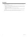
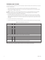
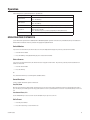
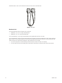
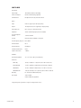
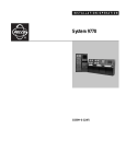
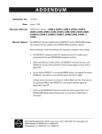
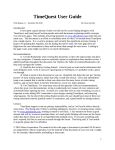
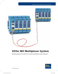
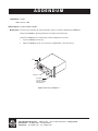
Manual Update The front and rear mounting rails and the mounting brackets are no longer supplied with the CM9700-CC1.
Disregard the CM9700-CC1 mounting information in the above referenced manuals.
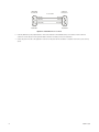
To mount the CM9700-CC1 into a standard 19-inch EIA rack follow these instructions:
1.
Insert the CM9700-CC1 into the rack.
2.
Tighten the CM9700-CC1 to the rack using the four supplied Phillips screws with washers.
RACK
CM9700-CC1
(4) SCREWS,
10-32 X 0.750-INCH
PHILLIPS, PAN HEAD
WITH WASHERS
Figure 1. Mounting the CM9700-CC1
Pelco Worldwide Headquarters • 3500 Pelco Way • Clovis, California 93612 USA • www.pelco.com
USA & Canada • Tel: 800/289-9100 • Fax: 800/289-9150
International • Tel: 1-559/292-1981 • Fax: 1-559/348-1120
INSTALLATION/OPERATION
System 9770
®
C1555M-F (10/05)
Contents
Contents. . . . . . . . . . . . . . . . . . . . . . . . . . . . . . . . . . . . . . . . . . . . . . . . . . . . . . . . . . . . . . . . . . . . . . . . . . . . . . . . . . . . . . . . . . . . . . . . . . . . . . . . . . . . .3
List of Illustrations . . . . . . . . . . . . . . . . . . . . . . . . . . . . . . . . . . . . . . . . . . . . . . . . . . . . . . . . . . . . . . . . . . . . . . . . . . . . . . . . . . . . . . . . . . . . . . . . . . . . .4
Description . . . . . . . . . . . . . . . . . . . . . . . . . . . . . . . . . . . . . . . . . . . . . . . . . . . . . . . . . . . . . . . . . . . . . . . . . . . . . . . . . . . . . . . . . . . . . . . . . . . . . . . . . .6
Models . . . . . . . . . . . . . . . . . . . . . . . . . . . . . . . . . . . . . . . . . . . . . . . . . . . . . . . . . . . . . . . . . . . . . . . . . . . . . . . . . . . . . . . . . . . . . . . . . . . . . . . . .7
Installation . . . . . . . . . . . . . . . . . . . . . . . . . . . . . . . . . . . . . . . . . . . . . . . . . . . . . . . . . . . . . . . . . . . . . . . . . . . . . . . . . . . . . . . . . . . . . . . . . . . . . . . . . .9
Unpacking . . . . . . . . . . . . . . . . . . . . . . . . . . . . . . . . . . . . . . . . . . . . . . . . . . . . . . . . . . . . . . . . . . . . . . . . . . . . . . . . . . . . . . . . . . . . . . . . . . . . . .9
Mounting . . . . . . . . . . . . . . . . . . . . . . . . . . . . . . . . . . . . . . . . . . . . . . . . . . . . . . . . . . . . . . . . . . . . . . . . . . . . . . . . . . . . . . . . . . . . . . . . . . . . . .10
Video Input/Output Connections . . . . . . . . . . . . . . . . . . . . . . . . . . . . . . . . . . . . . . . . . . . . . . . . . . . . . . . . . . . . . . . . . . . . . . . . . . . . . . . . . . . .13
Installing Video Input Cards (CM9770-VCC) . . . . . . . . . . . . . . . . . . . . . . . . . . . . . . . . . . . . . . . . . . . . . . . . . . . . . . . . . . . . . . . . . . . . . . .14
Installing Monitor Output Cards (CM9770-VMC) . . . . . . . . . . . . . . . . . . . . . . . . . . . . . . . . . . . . . . . . . . . . . . . . . . . . . . . . . . . . . . . . . . .15
Performing a Basic LED Check . . . . . . . . . . . . . . . . . . . . . . . . . . . . . . . . . . . . . . . . . . . . . . . . . . . . . . . . . . . . . . . . . . . . . . . . . . . . . . . . .16
Installing Rear Panel BNC Cards . . . . . . . . . . . . . . . . . . . . . . . . . . . . . . . . . . . . . . . . . . . . . . . . . . . . . . . . . . . . . . . . . . . . . . . . . . . . . . .17
Video Input/Output Capacity . . . . . . . . . . . . . . . . . . . . . . . . . . . . . . . . . . . . . . . . . . . . . . . . . . . . . . . . . . . . . . . . . . . . . . . . . . . . . . . . . . . . . . .21
The Power Supply Module (CM9700-MPS) . . . . . . . . . . . . . . . . . . . . . . . . . . . . . . . . . . . . . . . . . . . . . . . . . . . . . . . . . . . . . . . . . . . . . . . . . . . .26
Install a Backup Power Supply . . . . . . . . . . . . . . . . . . . . . . . . . . . . . . . . . . . . . . . . . . . . . . . . . . . . . . . . . . . . . . . . . . . . . . . . . . . . . . . . .26
Remove a Backup Power Supply . . . . . . . . . . . . . . . . . . . . . . . . . . . . . . . . . . . . . . . . . . . . . . . . . . . . . . . . . . . . . . . . . . . . . . . . . . . . . . .26
How to Replace the Fuse in a Power Supply Module . . . . . . . . . . . . . . . . . . . . . . . . . . . . . . . . . . . . . . . . . . . . . . . . . . . . . . . . . . . . . . .27
How to Turn Off the Audible Power Supply Alarm . . . . . . . . . . . . . . . . . . . . . . . . . . . . . . . . . . . . . . . . . . . . . . . . . . . . . . . . . . . . . . . . . .28
System Device Connections . . . . . . . . . . . . . . . . . . . . . . . . . . . . . . . . . . . . . . . . . . . . . . . . . . . . . . . . . . . . . . . . . . . . . . . . . . . . . . . . . . . . . . .29
RS-422 COM Port (“Sercom”) Connections . . . . . . . . . . . . . . . . . . . . . . . . . . . . . . . . . . . . . . . . . . . . . . . . . . . . . . . . . . . . . . . . . . . . . . . . . . . .31
System Start-Up . . . . . . . . . . . . . . . . . . . . . . . . . . . . . . . . . . . . . . . . . . . . . . . . . . . . . . . . . . . . . . . . . . . . . . . . . . . . . . . . . . . . . . . . . . . . . . . . . . . . .34
Initialize the CC1 . . . . . . . . . . . . . . . . . . . . . . . . . . . . . . . . . . . . . . . . . . . . . . . . . . . . . . . . . . . . . . . . . . . . . . . . . . . . . . . . . . . . . . . . . . . . . . . .34
Verify System Operation . . . . . . . . . . . . . . . . . . . . . . . . . . . . . . . . . . . . . . . . . . . . . . . . . . . . . . . . . . . . . . . . . . . . . . . . . . . . . . . . . . . . . . . . . .35
Initialize Keyboards . . . . . . . . . . . . . . . . . . . . . . . . . . . . . . . . . . . . . . . . . . . . . . . . . . . . . . . . . . . . . . . . . . . . . . . . . . . . . . . . . . . . . . . . . .35
Display the CM9770-MXB Software Version Level . . . . . . . . . . . . . . . . . . . . . . . . . . . . . . . . . . . . . . . . . . . . . . . . . . . . . . . . . . . . . . . . .36
Display a Blue Raster Screen . . . . . . . . . . . . . . . . . . . . . . . . . . . . . . . . . . . . . . . . . . . . . . . . . . . . . . . . . . . . . . . . . . . . . . . . . . . . . . . . . .36
Monitor Color Adjustment . . . . . . . . . . . . . . . . . . . . . . . . . . . . . . . . . . . . . . . . . . . . . . . . . . . . . . . . . . . . . . . . . . . . . . . . . . . . . . . . . . . .36
Programming Your System . . . . . . . . . . . . . . . . . . . . . . . . . . . . . . . . . . . . . . . . . . . . . . . . . . . . . . . . . . . . . . . . . . . . . . . . . . . . . . . . . . . . . . . . . . . . .37
Getting Help Using CM9700-MGR . . . . . . . . . . . . . . . . . . . . . . . . . . . . . . . . . . . . . . . . . . . . . . . . . . . . . . . . . . . . . . . . . . . . . . . . . . . . . .38
Operation . . . . . . . . . . . . . . . . . . . . . . . . . . . . . . . . . . . . . . . . . . . . . . . . . . . . . . . . . . . . . . . . . . . . . . . . . . . . . . . . . . . . . . . . . . . . . . . . . . . . . . . . . .39
Operating Your System 9770 . . . . . . . . . . . . . . . . . . . . . . . . . . . . . . . . . . . . . . . . . . . . . . . . . . . . . . . . . . . . . . . . . . . . . . . . . . . . . . . . . . . . . . .39
Appendix . . . . . . . . . . . . . . . . . . . . . . . . . . . . . . . . . . . . . . . . . . . . . . . . . . . . . . . . . . . . . . . . . . . . . . . . . . . . . . . . . . . . . . . . . . . . . . . . . . . . . . . . . . .40
System Architecture . . . . . . . . . . . . . . . . . . . . . . . . . . . . . . . . . . . . . . . . . . . . . . . . . . . . . . . . . . . . . . . . . . . . . . . . . . . . . . . . . . . . . . . . . . . . .40
How to Expand Your System . . . . . . . . . . . . . . . . . . . . . . . . . . . . . . . . . . . . . . . . . . . . . . . . . . . . . . . . . . . . . . . . . . . . . . . . . . . . . . . . . . . . . . .40
Installing Additional Matrix Bays—Sideframing and Downframing . . . . . . . . . . . . . . . . . . . . . . . . . . . . . . . . . . . . . . . . . . . . . . . . . . . .41
How to Install or Replace a CM9700-SER Card in the CC1 . . . . . . . . . . . . . . . . . . . . . . . . . . . . . . . . . . . . . . . . . . . . . . . . . . . . . . . . . . .46
Video Input Card (CM9770-VCC) Detail . . . . . . . . . . . . . . . . . . . . . . . . . . . . . . . . . . . . . . . . . . . . . . . . . . . . . . . . . . . . . . . . . . . . . . . . . . . . . . .48
Monitor Output Card (CM9770-VMC) Detail . . . . . . . . . . . . . . . . . . . . . . . . . . . . . . . . . . . . . . . . . . . . . . . . . . . . . . . . . . . . . . . . . . . . . . . . . . .49
Networking . . . . . . . . . . . . . . . . . . . . . . . . . . . . . . . . . . . . . . . . . . . . . . . . . . . . . . . . . . . . . . . . . . . . . . . . . . . . . . . . . . . . . . . . . . . . . . . . . . . .51
Connecting Satellite Devices . . . . . . . . . . . . . . . . . . . . . . . . . . . . . . . . . . . . . . . . . . . . . . . . . . . . . . . . . . . . . . . . . . . . . . . . . . . . . . . . . . . . . . .52
Programming Satellite Devices . . . . . . . . . . . . . . . . . . . . . . . . . . . . . . . . . . . . . . . . . . . . . . . . . . . . . . . . . . . . . . . . . . . . . . . . . . . . . . . .52
How to Install Video Patch Panels (CM9700-VPP) . . . . . . . . . . . . . . . . . . . . . . . . . . . . . . . . . . . . . . . . . . . . . . . . . . . . . . . . . . . . . . . . . . . . . .53
Mounting the CM9770-MXB in an Open Rack . . . . . . . . . . . . . . . . . . . . . . . . . . . . . . . . . . . . . . . . . . . . . . . . . . . . . . . . . . . . . . . . . . . . . . . . .54
DOS Environment and Command Reference . . . . . . . . . . . . . . . . . . . . . . . . . . . . . . . . . . . . . . . . . . . . . . . . . . . . . . . . . . . . . . . . . . . . . . . . . . .55
The Boot Process . . . . . . . . . . . . . . . . . . . . . . . . . . . . . . . . . . . . . . . . . . . . . . . . . . . . . . . . . . . . . . . . . . . . . . . . . . . . . . . . . . . . . . . . . . .55
AUTOEXEC.BAT and the Boot Process . . . . . . . . . . . . . . . . . . . . . . . . . . . . . . . . . . . . . . . . . . . . . . . . . . . . . . . . . . . . . . . . . . . . . . . . . . .55
DOS Reference . . . . . . . . . . . . . . . . . . . . . . . . . . . . . . . . . . . . . . . . . . . . . . . . . . . . . . . . . . . . . . . . . . . . . . . . . . . . . . . . . . . . . . . . . . . . .58
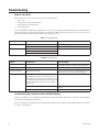
Troubleshooting . . . . . . . . . . . . . . . . . . . . . . . . . . . . . . . . . . . . . . . . . . . . . . . . . . . . . . . . . . . . . . . . . . . . . . . . . . . . . . . . . . . . . . . . . . . . . . . . . . . . .60
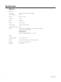
Specifications . . . . . . . . . . . . . . . . . . . . . . . . . . . . . . . . . . . . . . . . . . . . . . . . . . . . . . . . . . . . . . . . . . . . . . . . . . . . . . . . . . . . . . . . . . . . . . . . . . . . . . .62
Regulatory Notices . . . . . . . . . . . . . . . . . . . . . . . . . . . . . . . . . . . . . . . . . . . . . . . . . . . . . . . . . . . . . . . . . . . . . . . . . . . . . . . . . . . . . . . . . . . . . . . . . . .64
C1555M-F (10/05)
3
List of Illustrations
1
2
3
4
5
6
7
8
9
10
11
12
13
14
15
16
17
18
19
20
21
22
23
24
25
26
27
28
29
30
31
32
33
34
35
36
37
38
39
40
41
42
43
44
45
46
4
CM9770-MXB Mounting Baffle . . . . . . . . . . . . . . . . . . . . . . . . . . . . . . . . . . . . . . . . . . . . . . . . . . . . . . . . . . . . . . . . . . . . . . . . . . . . . . . . . . .10
Mounting the CM9770-MXB on Top of the Mounting Baffle . . . . . . . . . . . . . . . . . . . . . . . . . . . . . . . . . . . . . . . . . . . . . . . . . . . . . . . . . . . .11
Mounting the CM9700-CC1 . . . . . . . . . . . . . . . . . . . . . . . . . . . . . . . . . . . . . . . . . . . . . . . . . . . . . . . . . . . . . . . . . . . . . . . . . . . . . . . . . . . . . .12
Video Input Card (CM9770-VCC) Locations: Slots 1-8 . . . . . . . . . . . . . . . . . . . . . . . . . . . . . . . . . . . . . . . . . . . . . . . . . . . . . . . . . . . . . . . . .14
Monitor Output Card (CM9770-VMC) Locations: Slots 9-10 . . . . . . . . . . . . . . . . . . . . . . . . . . . . . . . . . . . . . . . . . . . . . . . . . . . . . . . . . . . .15
Insert a Rear Panel Video BNC Card (CM9770-RPC). . . . . . . . . . . . . . . . . . . . . . . . . . . . . . . . . . . . . . . . . . . . . . . . . . . . . . . . . . . . . . . . . . .17
Remove a Rear Panel Video BNC Card (CM9770-RPC) . . . . . . . . . . . . . . . . . . . . . . . . . . . . . . . . . . . . . . . . . . . . . . . . . . . . . . . . . . . . . . . . .17
CM9770-RPC Termination Jumpers—Right Card . . . . . . . . . . . . . . . . . . . . . . . . . . . . . . . . . . . . . . . . . . . . . . . . . . . . . . . . . . . . . . . . . . . . .18
CM9770-RPC Termination Jumpers—Left Card . . . . . . . . . . . . . . . . . . . . . . . . . . . . . . . . . . . . . . . . . . . . . . . . . . . . . . . . . . . . . . . . . . . . . .18
Looping Video Out from the CM9770-MXB . . . . . . . . . . . . . . . . . . . . . . . . . . . . . . . . . . . . . . . . . . . . . . . . . . . . . . . . . . . . . . . . . . . . . . . . . .19
CM9770-MXB Matrix Bay—16 Monitor Output Connections for Each VMC Card. . . . . . . . . . . . . . . . . . . . . . . . . . . . . . . . . . . . . . . . . . . .20
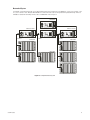
Sample CM9770 System with 256 Cameras and 32 Monitors . . . . . . . . . . . . . . . . . . . . . . . . . . . . . . . . . . . . . . . . . . . . . . . . . . . . . . . . . . .21
Sample System Using Sideframing from Bay to Bay. . . . . . . . . . . . . . . . . . . . . . . . . . . . . . . . . . . . . . . . . . . . . . . . . . . . . . . . . . . . . . . . . . .22
Sample Sideframing System Using an Output Bay . . . . . . . . . . . . . . . . . . . . . . . . . . . . . . . . . . . . . . . . . . . . . . . . . . . . . . . . . . . . . . . . . . . .23
Sample Single-Node System with Downframing . . . . . . . . . . . . . . . . . . . . . . . . . . . . . . . . . . . . . . . . . . . . . . . . . . . . . . . . . . . . . . . . . . . . .24
Sample Networked System . . . . . . . . . . . . . . . . . . . . . . . . . . . . . . . . . . . . . . . . . . . . . . . . . . . . . . . . . . . . . . . . . . . . . . . . . . . . . . . . . . . . . .25
How to Install or Remove a Power Supply. . . . . . . . . . . . . . . . . . . . . . . . . . . . . . . . . . . . . . . . . . . . . . . . . . . . . . . . . . . . . . . . . . . . . . . . . . .26
How to Replace a Power Supply Fuse . . . . . . . . . . . . . . . . . . . . . . . . . . . . . . . . . . . . . . . . . . . . . . . . . . . . . . . . . . . . . . . . . . . . . . . . . . . . .27
Power Supply Alarm Speaker Switch . . . . . . . . . . . . . . . . . . . . . . . . . . . . . . . . . . . . . . . . . . . . . . . . . . . . . . . . . . . . . . . . . . . . . . . . . . . . . .28
Connect the CM9760-KBD to the CM9700-CC1 . . . . . . . . . . . . . . . . . . . . . . . . . . . . . . . . . . . . . . . . . . . . . . . . . . . . . . . . . . . . . . . . . . . . . .29
CM9700-CC1 Device Connections . . . . . . . . . . . . . . . . . . . . . . . . . . . . . . . . . . . . . . . . . . . . . . . . . . . . . . . . . . . . . . . . . . . . . . . . . . . . . . . . .29
CM9700-MGR PC Pin-Out Detail . . . . . . . . . . . . . . . . . . . . . . . . . . . . . . . . . . . . . . . . . . . . . . . . . . . . . . . . . . . . . . . . . . . . . . . . . . . . . . . . . .30
Sample CM9770-MXB to CM9700-CC1 Connection . . . . . . . . . . . . . . . . . . . . . . . . . . . . . . . . . . . . . . . . . . . . . . . . . . . . . . . . . . . . . . . . . . .33
Sample CM9770-MXB and CM9700-CC1 Connections in a Networked System . . . . . . . . . . . . . . . . . . . . . . . . . . . . . . . . . . . . . . . . . . . . .33
CC1 Initialization . . . . . . . . . . . . . . . . . . . . . . . . . . . . . . . . . . . . . . . . . . . . . . . . . . . . . . . . . . . . . . . . . . . . . . . . . . . . . . . . . . . . . . . . . . . . . .34
System 9770 Color Bars . . . . . . . . . . . . . . . . . . . . . . . . . . . . . . . . . . . . . . . . . . . . . . . . . . . . . . . . . . . . . . . . . . . . . . . . . . . . . . . . . . . . . . . . .36
Getting Started Dialog Box . . . . . . . . . . . . . . . . . . . . . . . . . . . . . . . . . . . . . . . . . . . . . . . . . . . . . . . . . . . . . . . . . . . . . . . . . . . . . . . . . . . . . .37
Sample Wizard Page . . . . . . . . . . . . . . . . . . . . . . . . . . . . . . . . . . . . . . . . . . . . . . . . . . . . . . . . . . . . . . . . . . . . . . . . . . . . . . . . . . . . . . . . . . .38
CM9700-MGR Main Window - Properties Section . . . . . . . . . . . . . . . . . . . . . . . . . . . . . . . . . . . . . . . . . . . . . . . . . . . . . . . . . . . . . . . . . . . .38
CM9700-MGR Main Window - Help Section . . . . . . . . . . . . . . . . . . . . . . . . . . . . . . . . . . . . . . . . . . . . . . . . . . . . . . . . . . . . . . . . . . . . . . . .38
Downframing with DFC Cards . . . . . . . . . . . . . . . . . . . . . . . . . . . . . . . . . . . . . . . . . . . . . . . . . . . . . . . . . . . . . . . . . . . . . . . . . . . . . . . . . . . .43
Looping Video Out in a Downframed Configuration . . . . . . . . . . . . . . . . . . . . . . . . . . . . . . . . . . . . . . . . . . . . . . . . . . . . . . . . . . . . . . . . . . .43
DFC Cable . . . . . . . . . . . . . . . . . . . . . . . . . . . . . . . . . . . . . . . . . . . . . . . . . . . . . . . . . . . . . . . . . . . . . . . . . . . . . . . . . . . . . . . . . . . . . . . . . . . .44
DFC Card . . . . . . . . . . . . . . . . . . . . . . . . . . . . . . . . . . . . . . . . . . . . . . . . . . . . . . . . . . . . . . . . . . . . . . . . . . . . . . . . . . . . . . . . . . . . . . . . . . . .45
CM9770-DFL Card . . . . . . . . . . . . . . . . . . . . . . . . . . . . . . . . . . . . . . . . . . . . . . . . . . . . . . . . . . . . . . . . . . . . . . . . . . . . . . . . . . . . . . . . . . . . .45
Removing the CC1 Top Cover . . . . . . . . . . . . . . . . . . . . . . . . . . . . . . . . . . . . . . . . . . . . . . . . . . . . . . . . . . . . . . . . . . . . . . . . . . . . . . . . . . . . .46
SER Card Jumper Assignments . . . . . . . . . . . . . . . . . . . . . . . . . . . . . . . . . . . . . . . . . . . . . . . . . . . . . . . . . . . . . . . . . . . . . . . . . . . . . . . . . . .47
How to Install a CM9700-SER Card . . . . . . . . . . . . . . . . . . . . . . . . . . . . . . . . . . . . . . . . . . . . . . . . . . . . . . . . . . . . . . . . . . . . . . . . . . . . . . . .47
CM9770-VCC Card . . . . . . . . . . . . . . . . . . . . . . . . . . . . . . . . . . . . . . . . . . . . . . . . . . . . . . . . . . . . . . . . . . . . . . . . . . . . . . . . . . . . . . . . . . . . .48
CM9770-VMC Card . . . . . . . . . . . . . . . . . . . . . . . . . . . . . . . . . . . . . . . . . . . . . . . . . . . . . . . . . . . . . . . . . . . . . . . . . . . . . . . . . . . . . . . . . . . .49
Sample Networked System . . . . . . . . . . . . . . . . . . . . . . . . . . . . . . . . . . . . . . . . . . . . . . . . . . . . . . . . . . . . . . . . . . . . . . . . . . . . . . . . . . . . . .51
Sample Satellite System . . . . . . . . . . . . . . . . . . . . . . . . . . . . . . . . . . . . . . . . . . . . . . . . . . . . . . . . . . . . . . . . . . . . . . . . . . . . . . . . . . . . . . . .52
Add a Satellite Device . . . . . . . . . . . . . . . . . . . . . . . . . . . . . . . . . . . . . . . . . . . . . . . . . . . . . . . . . . . . . . . . . . . . . . . . . . . . . . . . . . . . . . . . . .52
CM9700-VPP Horizontal Mount . . . . . . . . . . . . . . . . . . . . . . . . . . . . . . . . . . . . . . . . . . . . . . . . . . . . . . . . . . . . . . . . . . . . . . . . . . . . . . . . . . .53
CM9700-VPP Vertical Mount . . . . . . . . . . . . . . . . . . . . . . . . . . . . . . . . . . . . . . . . . . . . . . . . . . . . . . . . . . . . . . . . . . . . . . . . . . . . . . . . . . . . .53
Mounting the CM9770-MXB in an Open Rack. . . . . . . . . . . . . . . . . . . . . . . . . . . . . . . . . . . . . . . . . . . . . . . . . . . . . . . . . . . . . . . . . . . . . . . .54
C1555M-F (10/05)
List of Tables
A
B
C
D
E
F
G
H
I
J
K
L
M
N
LEDs Illuminated During a Basic Check . . . . . . . . . . . . . . . . . . . . . . . . . . . . . . . . . . . . . . . . . . . . . . . . . . . . . . . . . . . . . . . . . . . . . . . . . . . . . . .16
Data Connections—Single Node Systems Without a Hot Switch . . . . . . . . . . . . . . . . . . . . . . . . . . . . . . . . . . . . . . . . . . . . . . . . . . . . . . . . . .31
Data Connections—Networked System Without a Hot Switch . . . . . . . . . . . . . . . . . . . . . . . . . . . . . . . . . . . . . . . . . . . . . . . . . . . . . . . . . . . .31
Data Connections—Single Node, Hot-Switched System . . . . . . . . . . . . . . . . . . . . . . . . . . . . . . . . . . . . . . . . . . . . . . . . . . . . . . . . . . . . . . . . .32
Data Connections—Networked, Hot-Switched System . . . . . . . . . . . . . . . . . . . . . . . . . . . . . . . . . . . . . . . . . . . . . . . . . . . . . . . . . . . . . . . . . .32
SER Card Jumper Assignments for a CM9700-CC1 System Control . . . . . . . . . . . . . . . . . . . . . . . . . . . . . . . . . . . . . . . . . . . . . . . . . . . . . . . . .46
SER Card Jumper Assignments for a CM9700-NW1 Network Interface Unit. . . . . . . . . . . . . . . . . . . . . . . . . . . . . . . . . . . . . . . . . . . . . . . . . .46
Video Input Card (CM9770-VCC) LEDs . . . . . . . . . . . . . . . . . . . . . . . . . . . . . . . . . . . . . . . . . . . . . . . . . . . . . . . . . . . . . . . . . . . . . . . . . . . . . . . .48
Monitor Output Card (CM9770-VMC) LEDs . . . . . . . . . . . . . . . . . . . . . . . . . . . . . . . . . . . . . . . . . . . . . . . . . . . . . . . . . . . . . . . . . . . . . . . . . . . .49
Monitor Output Card DIP Switch . . . . . . . . . . . . . . . . . . . . . . . . . . . . . . . . . . . . . . . . . . . . . . . . . . . . . . . . . . . . . . . . . . . . . . . . . . . . . . . . . . . .50
DOS Command Reference Directory. . . . . . . . . . . . . . . . . . . . . . . . . . . . . . . . . . . . . . . . . . . . . . . . . . . . . . . . . . . . . . . . . . . . . . . . . . . . . . . . . .58
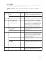
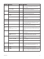
CC1 Hardware Errors . . . . . . . . . . . . . . . . . . . . . . . . . . . . . . . . . . . . . . . . . . . . . . . . . . . . . . . . . . . . . . . . . . . . . . . . . . . . . . . . . . . . . . . . . . . . .60
CC1 System Errors . . . . . . . . . . . . . . . . . . . . . . . . . . . . . . . . . . . . . . . . . . . . . . . . . . . . . . . . . . . . . . . . . . . . . . . . . . . . . . . . . . . . . . . . . . . . . . .60
Monitor Output Card DIP Switch 1 . . . . . . . . . . . . . . . . . . . . . . . . . . . . . . . . . . . . . . . . . . . . . . . . . . . . . . . . . . . . . . . . . . . . . . . . . . . . . . . . . . .61
C1555M-F (10/05)
5
Description
The System 9770 is a full-featured video matrix switching control system that allows users to view and control up to 2,048 cameras and
512 monitors on a single node.
The System 9770 has the following basic components:
•
CM9700-CC1—This is the system CPU; connect matrix bays, keyboards, PTZ camera control lines, and peripheral devices to the CC1.
•
CM9770-MXB—This is the video matrix (switching) bay with video input/output modules; connect cameras, monitors, VCRs, and other
video input and output devices to the MXB.
•
CM9760-KBD—This is the system keyboard, providing operator control of the System 9770.
•
CM9700-MGR installed on an external PC—This is the system management software providing an easy method of system setup and
configuration.
In addition to the basic components, you can also use peripheral CM9760 equipment in a System 9770, such as KBD300A keyboards (an
alternate keyboard for operator control), MDA units, ALM units, REL units, Genex® multiplexers, and Pelco VCRs.
6
C1555M-F (10/05)
MODELS
Controller and CPU Components
CM9700-CC1
CPU controller; 120 VAC, 60 Hz or 230 VAC, 50 Hz.
CM9700-SER
Serial communication card (RS-422 SERCOM); provides 8 communications ports to interface peripheral equipment
(4 maximum per CPU).
CM9700-SER-32
Port expansion unit; 32 serial communication (SERCOM) ports per unit. Up to three units can be added to a CC1.
(Check with Pelco Systems Applications Department before adding to an existing CM9700-CC1). Includes
interconnecting cables and adapters for DB9 and RJ-45 connectors. Data interface can be RS-232 or RS-422.
NOTES ON USING THE SYSTEM CPU:
•
You can use CM9760-CC1/CM9760-NW1 CPUs with the System 9770 if the CPU has been updated with software version level 9.01.XXX
(note that at this software level the first three digits—9.01 in this case—must be at the same version level in the CPU (CC1 and NW1) and
in the MGR software; the remaining three digits, such as .001 in version level 9.01.001, can vary).
•
Note, however, that software version level 9.01 requires a minimum of 16 MB of RAM in the CPU. If necessary, you can upgrade the RAM
in a CM9760-CC1 using the software upgrade kit appropriate for your CPU. Contact Pelco Technical Support at 1-800-289-9100 or
1-559-292-1981 for additional information.
Matrix Bay
CM9770-MXB
Video matrix bay equipped with one CM9700-MPS power supply; 100-240 VAC, 50/60 Hz, autoranging.
CM9700-MPS
Matrix bay power supply (spare); 120 VAC, 60 Hz or 230 VAC, 50Hz.
CM9770-DFC
Downframe card and cable assembly; connects multiple matrix bays for expansion purposes.
CM9770-DFL
Downframe card and cable assembly with BNC connectors for looping video.
CM9770-VCC
Video camera card capable of accepting up to 32 camera inputs; also requires a rear panel card (CM9770-DFC,
CM9770-DFL, or CM9770-RPC).
CM9770-RPC
Rear panel video card; provides 32 BNC connectors used to connect camera inputs to matrix bay.
CM9770-VMC
Video monitor card providing 16 monitor outputs; requires CM9770-RPM.
CM9770-RPM
Rear panel monitor card; provides 16 BNCs to connect monitor outputs to matrix bay; also interfaces video output
signals from video output card.
CM9700-VPP
Video patch panel; provides 32 BNC connections for looping video out of system.
CM9700-VPP-RK
Optional rack mount designed to hold up to 16 CM9700-VPP patch panels.
Network Interface Unit
CM9700-NW1
C1555M-F (10/05)
Network interface unit; network CPU and software necessary for joining two or more independent systems together.
7
Keyboards
The following keyboards are compatible with the System 9770:
CM9760-KBD
Full-function desktop variable-speed keyboard; 120 VAC, 60 Hz.
CM9760-KBD-X
Same as CM9760-KBD except 230 VAC, 50 Hz.
CM9760-KBR
Full-function 19-inch EIA rack mount keyboard; 120 VAC, 60 Hz.
CM9760-KBR-X
Same as CM9760-KBR except 230 VAC, 50 Hz.
NOTE: CM9760-KBD software version 8.03 or higher is required.
KBD200A
Desktop keyboard with full switching capabilities, plus push-button control of PTZ functions; 12 VAC or ±12 VDC.
(Requires KBDKIT for power.)
KBD300A
Desktop keyboard with full switching capabilities, plus joystick control of PTZ functions; 12 VAC or ±12 VDC.
(Requires KBDKIT for power.)
Optional Components
CM9760-ALM
Alarm interface unit; connects directly to each system; each unit can monitor up to 64 alarms; up to four units can be
connected in a series from one SERCOM port.
CM9760-CDU-T
Code distribution unit; 16-channel RS-422 transmit-only (two data wires and ground) distributor. Primarily used for
wiring up to 16 pan/tilt/zoom receivers in a “star” configuration.
CM9760-CXTA
Coaxitron® translator; generates Coaxitron signals for Pelco Coaxitron receivers; each translator supports up to
16 receivers.
CM9760-DMR
Data merger and port expander unit; this unit allows multiple CM9700-CC1 units to control multiple pan/tilt/zoom
cameras and allows multiple keyboards to communicate through one CC1 port.
CM9760-DMR-X
Same as CM9760-DMR except 230 VAC, 50 Hz.
VMX200 and
VMX300 Series
Video management systems; graphical map/icon-based user interface for mouse-driven operator control from
external PC.
CM9760-HS
Hot switch interface unit; changeover unit that monitors the status of a primary CC1 in a 9770 system.
CM9760-MDA
Master distribution amplifier; inserts master time and date from the CM9700-CC1 and a programmable title of up to
24 characters on 1 to 16 video signals.
CM9760-MDA-X
Same as CM9760-MDA except 230 VAC, 50 Hz.
CM9760-REL
Relay interface unit; connects directly to each system and provides dry contact switching for direct or automatic
control of peripheral equipment; each unit provides up to 64 SPST contact outputs.
Genex Multiplexers
Genex Series MX4009 (9-channel) and MX4016 (16-channel) multiplexers.
CM9760-VCRC
CM9760-VCRC Series VCR Controller; VCR control unit capable of controlling 64 VCRs.
Compatible Receivers
8
Spectra® Series
Spectra dome multiple protocol receiver.
ERD97P21-U
Pelco P-protocol receiver.
LRD41C21-1/-2/-3
Legacy® fixed speed receiver with presets.
LRD41C22-1/-2/-3
Same as LRD41C21 Series except variable speed receiver.
Esprit®
Integrated pan/tilt positioning receiver.
Coaxitron
Coaxitron translator allows Coaxitron control of PTZ cameras.
C1555M-F (10/05)
Installation
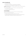
UNPACKING
1. Unpack and inspect all equipment, and verify delivery according to the packing slip.
Before shipping, Pelco connects, tests, and programs each system according to the individual sales order. Contact Pelco immediately if
there is any discrepancy in the equipment that you receive.
CM9700-CC1
The following items are supplied with the CM9700-CC1:
•
1 CM9700-CC1 unit, with front rack ears installed
•
1 120 VAC, 60 Hz power cord (USA standard)
•
1 230 VAC, 50 Hz power cord (European standard)
•
1 Keyboard, PS/2
•
1 PS/2-to-AT keyboard adapter
•
1 RCA-to-BNC adapter
•
CM9700 Resource CD (includes the CM9700-MGR software)
•
BNC extraction tool
•
2 Brackets with a set of 6 screws, 8-32 x .250-inch, pan head
•
2 Adjustable support rail sets (each set includes 1 front-mounting rail and 1 rear-mounting rail), with the following sets of screws
–
6 Screws, 8-32 x .375-inch, pan head with washers
–
12 Screws, 10-32 x .375-inch, flat head
–
4 Screws, 10-32 x .750-inch, Phillips, pan head with washers
–
6 Screws, 8-32 x .250-inch, Phillips, pan head
CM9770-MXB
The following items are supplied with the CM9770-MXB:
•
1 CM9770-MXB matrix bay, with front rack ears installed
•
1 CM9770-MXB mounting baffle, with front and rear rack ears installed
•
1 120 VAC, 60 Hz power cord (USA standard)
•
1 230 VAC, 50 Hz power cord (European standard)
•
1 RJ-45 reversed data cable
•
1 Sheet of camera number labels (these can be affixed to the BNC cards to correspond to camera input numbers)
•
16 Screws and washers for mounting the bay
NOTE: The appropriate number of CM9770-VCC cards (camera cards), CM9770-VMC cards (monitor cards), and associated rear panels are
added to your system according to your system order.
2. Keep all manuals and cabling with their associated equipment.
3. Locate the following documents:
C1555M-F (10/05)
•
The System 9770 Port Assignments Sheet. This document contains specific information about your system. All System 9770s are
preprogrammed based on your system order.
•
System 9770 manual binder.
9
MOUNTING
Install the System 9770 in EIA-standard 19-inch (48.26 cm) racks.
CM9770-MXB
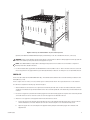
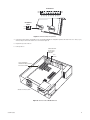
1. Install the CM9770-MXB mounting baffle first (refer to Figure 1).
The mounting baffle uses 1 rack unit (RU), and it has front and rear mounting ears, which are attached to the front and rear mounting racks.
The rear mounting brackets are adjustable to allow for different depths of cabinets.
NOTE: Be sure to use all eight screws provided with the mounting baffle. The mounting baffle must be installed securely to support the
weight of the matrix bay.
The mounting baffle provides the following functions:
•
The mounting baffle helps to direct the heat from a lower matrix bay (or other equipment) toward the rear of the mounting baffle,
instead of allowing the heat to flow up into the matrix bay.
•
The mounting baffle supports the weight of the matrix bay.
•
The matrix bay is easier to install when it is sitting on top of the mounting baffle.
Figure 1. CM9770-MXB Mounting Baffle
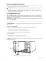
2. Install the CM9770-MXB matrix bay on top of the mounting baffle. Refer to Figure 2.
In a single-bay installation, always leave 1 RU of space above the matrix bay for airflow.
In a multiple-bay installation you do not need to leave additional RUs open between units. However, you must always leave 1 RU of space
above the upper bay.
NOTE: Figure 2 illustrates the recommended mounting method. For an alternate, open-rack mounting method, refer to the Mounting the
CM9770-MXB in an Open Rack section in the Appendix.
10
C1555M-F (10/05)
Figure 2. Mounting the CM9770-MXB on Top of the Mounting Baffle
(Optional) Install additional CM9770-MXB mounting trays and matrix bays to the side of and below the first unit, as necessary.
WARNING: Always install equipment starting from the bottom of the rack frame or cabinet. Installing equipment from the top down will
make a rack or cabinet top heavy and could cause the equipment to tip over.
NOTE: Each CM9770-MXB has a unique label for identifying the bay location in the installation. This ID information is important in
ensuring correct video and data connections.
3. Use the RJ-45 data cables supplied with each CM9770-MXB to connect the MXBs to the CC1. Refer to the Data Connections section and
the Port Assignments insert (supplied with the System 9770 documentation) for directions on which port to use for each MXB connection.
CM9700-CC1
The CC1 must be located near the CM9770-MXB matrix bays. The maximum distance between the CC1 and the matrix bays should be no more
than 4,000 feet (1,219 m).
The CC1 occupies 4 RUs or 7 inches (17.18 cm) of vertical space in a universal mount. Allow 1 RU of space above the CC1 for air circulation.
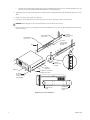
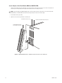
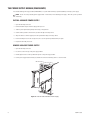
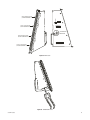
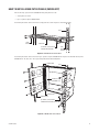
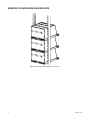
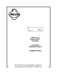
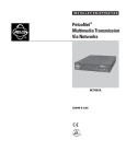
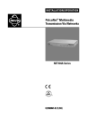
To install the CC1 complete the following steps and refer to Figure 3:
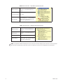
1. Attach one bracket to each side of the CC1 using three 8-32 x 0.250-inch pan head screws for each side. Attach each bracket so that the
slotted holes in the bracket are positioned toward the front of the CC1 and the tapered ends of the bracket are positioned toward the rear
of the CC1.
2. For each set of support rails, attach the front-mounting support rail to the rear-mounting support rail using three 8-32 x 0.375-inch pan head
screws and washers for each set. Leave the screws loose until the support rails are attached to the rack.
3. Attach one set of support rails to the equipment rack in the desired location as follows:
C1555M-F (10/05)
a.
Position the ear of the front-mounting support rail against the front of the equipment rack and align the holes in the ear of the rail
with the threaded holes in the rack. Attach the ear of the rail to the rack using two 10-32 x 0.375-inch flat head screws.
b.
Adjust the support rails to the correct depth of the equipment rack by sliding the rear-mounting support rail to the back of the
equipment rack.
11
c.
Attach the ear of the rear-mounting support rail to the rear of the equipment rack using four 10-32 x 0.375-inch flat head screws. (The
holes in the ear of the rail should align with the threaded holes in the equipment rack.)
4. Tighten the three 8-32 x 0.375-inch pan head screws and washers that were attached to the front- and rear-mounting support rails in step 2
above.
5. Repeat steps 3 and 4 for the second set of support rails.
6. Place the CC1 onto the support rails and slide the unit into the rack. The CC1 should slide in and out of the rack easily.
WARNING: When sliding the CC1 out of the rack, be careful not to let the unit fall out of the rack.
7. Fasten each rack ear of the CC1 to the equipment rack using two standard rack screws (10-32 x 0.750-inch Phillips pan head screws) and
washers for each ear.
(8) SCREWS,
10-32 X 0.375-INCH
FLAT HEAD
REAR MOUNTING
SUPPORT RAIL
FRONT MOUNTING
SUPPORT RAIL
(6) SCREWS,
8-32 X 0.375-INCH
PAN HEAD WITH
WASHERS
RACK
(4) SCREWS
10-32 X 0.375-INCH
FLAT HEAD
BRACKET
(SIDE VIEW)
CM9700-CC1
(6) SCREWS, 8-32 X 0.250-INCH
PAN HEAD (3 EACH SIDE)
(4) SCREWS,
10-32 X 0.750-INCH
PHILLIPS, PAN HEAD
WITH WASHERS
SLOTTED HOLES
TOWARDS FRONT
OF UNIT
TAPERED ENDS
TOWARDS REAR
OF UNIT
Figure 3. Mounting the CM9700-CC1
12
C1555M-F (10/05)
VIDEO INPUT/OUTPUT CONNECTIONS
The following steps provide an overview of how to connect video input and output sources. More complete procedures are provided in the
subsequent sections.
NOTE: If your System 9770 is configured by Pelco, the appropriate number of video input cards and monitor output cards and BNC rear
panels are installed at the factory, and steps 1 and 2 are not necessary. If this is the case, skip to Step 3.
1. Install the CM9770-VCC and CM9770-VMC cards in the matrix bay. Refer to the Installing Video Input Cards (CM9770-VCC) section and the
Installing Monitor Output Cards (CM9770-VMC) section in the following pages.
2. Slide the CM9770-RPC and CM9770-RPM BNC rear panels into the appropriate slots from the back of the matrix bay. Refer to the Insert or
Replace a Rear Panel Video BNC Card (CM9770-RPC) section and the Insert or Replace a Rear Panel Monitor BNC Card (CM9770-RPM)
section in the following pages.
3. Before you connect any video input or output to the matrix bay, you may want to power up the unit to ensure that the system is operating
properly. Refer to the Performing a Basic LED Check section.
4. Connect video inputs and monitor outputs to the rear panel BNC connectors on the CM9770-MXB matrix bay unit(s).
Installation Tips
•
Be sure each connection is secure. For best results, use crimp-on BNCs only. Do not use screw-on BNCs; these typically do not provide
adequate ground and signal connections.
•
Label each video input; this can save a considerable amount of troubleshooting time in the future.
•
Video output from the CM9770-VMC cards is not terminated. Terminate the video signal at the output device (monitor or VCR). If you are
looping to other devices, unterminate all but the last device.
NOTE: The end point of any video cable run must be terminated in 75 ohms.
Opening the CM9770-MXB Front Cover
To install or remove a video input card, monitor output card, or power supply, you must first open the CM9770-MXB front cover.
1. Loosen the two screws at the top of the CM9770-MXB frame.
2. Pull the front cover towards you. The hinges at the bottom keep the cover attached to the frame.
3. When you are finished working with the interior components, close the cover and tighten the screws at the top of the frame.
NOTE: Although the CM9770-MXB will function properly with the front cover open, the front cover must remain closed during system
operation to meet safety standards.
C1555M-F (10/05)
13
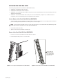
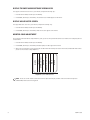
INSTALLING VIDEO INPUT CARDS (CM9770-VCC)
The first video input card is inserted into slot 1; the next card is inserted into slot 2 (refer to Figure 4). To add a video card, slide the card into the
first available slot. The CM9770-MXB can contain a maximum of eight viideo input cards.
HOT SWAPPING: You can “hot swap” a video input card—remove a card and/or insert a new card—while the system is powered and
running. When you hot swap a card, the CM9770-MXB automatically verifies system software levels on all cards and then updates
software on the new cards if necessary. This process can be as fast as 30 seconds, or can take up to 5 minutes, depending on the number
of differing software files; however, the matrix bay continues to function throughout this process. The process is complete when the LEDs
marked “HB” on the front panel blink at a one-second rate.
How to Turn On the Pelco V-Sync Signal
The Pelco V-Sync signal, which is sent up the coax cable, provides a synchronization pulse for cameras that can use the Pelco V-Sync signal. This
signal eliminates the vertical roll that occurs when multiple cameras are connected to the same switching device. To turn on the Pelco V-Sync
signal, move the jumper labeled “VSYNCH” on the CM9770-VCC video input card to the ON position. Refer to the CM9770-VCC Card illustration
in the Appendix to see where this jumper is located.
The Pelco V-Sync feature is either “all on” or “all off” (default) for every camera connected to the specific CM9770-VCC card. You cannot turn the
feature on or off for individual cameras.
For the Pelco V-Sync feature to work properly, all matrix bays in the system must be connected to the same power circuit (because they must be
in the same phase).
DOWNFRAMING NOTE: If you are downframing the video signal to additional bays, you need to turn on the Pelco V-Sync on the final
matrix bay only.
Insert or Replace a Video Card
1. Open the front of the matrix bay, insert the video card into the card guides, and slide the card partially into the bay.
2. Hold the latches parallel to the floor until you reach the edge of the bay’s frame.
3. Adjust the latches to fit them properly onto the top and bottom edges of the bay’s frame.
4. Push the latching levers into the closed position; this seats the video card firmly into place.
Remove a Video Card
1. Unlatch (pull) the levers at the top and bottom portion of the video card.
2. Pull the video card towards you (towards the front of the matrix bay) until it is out of the frame.
NOTE: Do not insert a video input card into slots 9 or 10; these slots are reserved for monitor output cards as shown in the Monitor Output
Cards (CM9770-VMC) section.
CM9770-VCC
SLOT 1
SLOT 2
SLOT 3
Figure 4. Video Input Card (CM9770-VCC) Locations: Slots 1-8
14
C1555M-F (10/05)
INSTALLING MONITOR OUTPUT CARDS (CM9770-VMC)
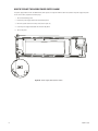
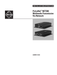
The monitor output card located in slot 10 is the primary card, and it handles video for monitors 1-16. Refer to Figure 5. Note that the
CM9770-MXB will not function without a CM9770-VMC card inserted into slot 10.
An optional secondary VMC card can be installed in slot 9. This card routes video for monitors 17-32.
HOT SWAPPING: You can “hot swap” a monitor output card—remove a card and/or insert a new card— while the system is powered
and running. When you hot swap a card, the CM9770-MXB automatically verifies system software levels on all video input cards and
monitor output cards in the matrix bay and then updates the software on any cards that do not match the VMC card in the primary VMC slot
(slot 10). This process can be as fast as 30 seconds, or can take up to 5 minutes, depending on the number of differing software files;
however, the matrix bay continues to function throughout this process. The process is complete when the LEDs marked “HB” on the front
panel blink at a one-second rate.
Insert or Replace a Monitor Card
CAUTION: When you insert a VMC card into the primary VMC slot—slot 10—the CM9770-MXB synchronizes software levels on all cards
in the matrix bay, based on the software contained on this card. If the new card inserted into the primary VMC slot contains software at a
lower level than the other cards in the matrix bay, you could lose some system settings and functionality.
1. Open the front of the matrix bay, insert the monitor card into the card guides, and slide the card partially into the bay.
2. Hold the latches parallel to the floor until you reach the edge of the bay’s frame.
3. Adjust the latches to fit them properly onto the top and bottom edges of the bay’s frame.
4. Push the latching levers into the closed position; this seats the monitor card firmly into place.
Remove a Monitor Card
1. Unlatch (pull) the levers at the top and bottom portion of the monitor card.
2. Pull the monitor card towards you (towards the front of the matrix bay) until it is out of the frame.
CM9770-VMC
MONITOR CARD SLOT 9
MONITOR CARD SLOT 10
Figure 5. Monitor Output Card (CM9770-VMC) Locations: Slots 9-10
C1555M-F (10/05)
15
PERFORMING A BASIC LED CHECK
You should perform a basic LED check before you connect any video input or output to the matrix bay. The LED check allows you to ensure that
the system is operating properly.
1. Turn on the power switch on the rear of the matrix bay. The front cover can either be open or closed during the LED check.
2. Various LEDs will blink during the initialization process as the software verifies communication and version level information. Once the
initialization process is complete, continue to step 3.
NOTE: The initialization process should take approximately 30 seconds, unless the primary CM9770-VMC monitor card is updating
software on the other monitor card or on the CM9770-VCC video cards. The software update process takes several minutes.
3. Ensure that the appropriate LEDs are illuminated, as described in Table A.
4. Ensure that the red CF LED on each video input card is off. If this LED is illuminated on any input card, reseat the card. If the problem
continues, replace with a known good video input card. If this LED is illuminated on all of the video input cards, there may be a problem
with the primary monitor output card (in slot 10). Reseat the primary monitor card. If the problem continues, replace with a known good
monitor card.
5. Ensure that the red VF and PF LEDs on the power supply are off.
6. If the LEDs are properly illuminated, turn off the power switch on the rear of the matrix bay, and then install all video inputs and outputs.
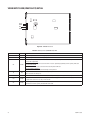
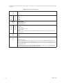
Table A. LEDs Illuminated During a Basic Check
Front Panel Label
Color
Diagnostic Check
+
Green
On.
-
Green
On.
Power Supply
Monitor Output Card (CM9770-VMC)
+
Green
On.
-
Green
On.
HB
Amber
Blinks at a one-second rate.
RX
Amber
Blinks during normal system operation as switching commands are sent and polled.
MP
Amber
Blinks during normal system operation.
NOTE: The amber FP, CP, and BP LEDs will blink on start-up, but should not remain illuminated.
Video Input Card (CM9770-VCC)
+
Green
On.
-
Green
On.
HB
Amber
Blinks at a one-second rate.
VL
Red
This is the video loss LED, and it should be illuminated because there are no video signals coming into the
rear panel yet. During normal operation this LED should be off.
NOTE: The amber CD LED may blink on start-up, but should not remain illuminated.
Refer to Table H and Table I in the Appendix for additional information on the LEDs and troubleshooting information.
16
C1555M-F (10/05)
INSTALLING REAR PANEL BNC CARDS
The following rear panel cards can be used with the CM9770-MXB matrix bay:
•
CM9770-RPC—the BNC card for video connections
•
CM9770-RPM—the BNC card for monitor connections
•
CM9770-DFC—this is a downframe card and cable assembly used to connect multiple matrix bays; refer to the Downframing section in the
Appendix for more information
•
CM9770-DFL—this downframe card and cable assembly is the same as the CM9770-DFC, except that it also has BNC connectors for
looping inputs; refer to the Downframing section in the Appendix for more information
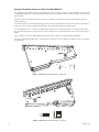
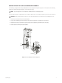
Insert or Replace a Rear Panel Video BNC Card (CM9770-RPC)
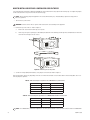
1. Slide the video BNC card into the card guides at the rear of the bay. From the rear of the bay, the slot at the far right provides the connection
point for the video input card inserted in the front of the bay into slot 1. Refer to Figure 6.
NOTE: You will note that the video BNC card consists of two cards connected into one unit. Each video BNC card (CM9770-RPC) provides
32 video input connections and connects to one video input card (CM9770-VCC).
2. Push the BNC card into place firmly.
3. Tighten the screws at the top and bottom of the BNC card.
Remove a Rear Panel Video BNC Card (CM9770-RPC)
1. Loosen the screws at the top and bottom of the BNC card. Refer to Figure 7.
2. Pull the BNC card towards you until it is out of the frame.
TWO RPC CARDS ARE
CONNECTED INTO ONE
UNIT - LOOSEN SCREWS
AT TOP AND BOTTOM TO
REMOVE RPC UNIT
Figure 6. Insert a Rear Panel Video BNC Card (CM9770-RPC)
C1555M-F (10/05)
Figure 7. Remove a Rear Panel Video BNC Card (CM9770-RPC)
17
Change the Termination Jumpers on a Rear Panel Video BNC Card
In a single-bay, non-looping configuration (up to 256 cameras and 32 monitors), the jumpers must be set in the terminated position. Refer to the
Installing Additional Matrix Bays—Sideframing and Downframing section in the Appendix for details on termination jumper settings in multiplebay configurations.
When looping video out to another device (such as a DVR, VCR, or switcher), set the termination jumpers on the CM9770-RPC cards to the
unterminated position.
The termination jumpers are set in the appropriate position when your system is configured at the factory by Pelco. However, if you expand or
change your system, or purchase a replacement CM9770-RPC card, you may need to change the termination yourself.
Since the CM9770-RPC consists of two cards assembled together, you must access the termination jumpers on each card in a different way.
Access the termination jumpers on the right-side card as shown in Figure 8. Access the termination jumpers on the left-side card as shown in
Figure 9.
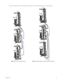
Figure 13 and Figure 14 illustrate sample sideframing configurations. Figure 15 illustrates a sample downframing configuration.
Refer to the Installing Additional Matrix Bays—Sideframing and Downframing section in the Appendix for detailed instructions on sideframing
and downframing.
1
2
3
Figure 8. CM9770-RPC Termination Jumpers—Right Card
3
1
Figure 9. CM9770-RPC Termination Jumpers—Left Card
18
C1555M-F (10/05)
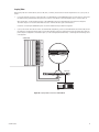
Looping Video
When looping video out to another device (such as a DVR, VCR, or switcher), the connection instructions depend on the size of your system, as
follows:
•
In a system containing 32 monitors or fewer (the video is not downframed), use the CM9700-VPP panels to loop the video out. Connect the
DFC cables that are provided with the VPP panel to the connectors on the bottom of the matrix bay RPC cards, as shown in Figure 10.
When looping video, set the termination jumpers on the CM9770-RPC cards to the unterminated position. Refer to the Change the
Termination Jumpers on a Rear Panel Video BNC Card section. Terminate the video signal at the final device.
Instructions on installing the CM9700-VPP panels into an EIA-standard rack are provided in the Appendix.
•
If your system contains more than 32 monitors (in a downframed configuration), you must use the CM9770-DFL card in the final bay. Use the
DFC cable that is provided with the DFC card to connect the downframe connector on the bottom of the DFL card with the DFC card in the
previous bay. This configuration is illustrated in Figure 31, in the Installing Additional Matrix Bays—Sideframing and Downframing section
of the Appendix.
CM9770-MXB
PORT B
PORT A
CM9700-VPP
PORT A
PORTB
DVR
Figure 10. Looping Video Out from the CM9770-MXB
C1555M-F (10/05)
19
Insert or Replace a Rear Panel Monitor BNC Card (CM9770-RPM)
1. Slide the monitor BNC card into the card guides at the rear of the bay. From the rear of the bay, the slot at the far left provides the
connection point for the primary monitor output card inserted in the front of the bay into slot 10.
NOTE: Each monitor BNC card (CM9770-RPM) provides 16 monitor output connections and connects to one monitor output card
(CM9770-VMC). The CM9770-MXB can hold two monitor output cards, for a total of 32 monitor outputs.
2. Push the BNC card into place firmly.
3. Tighten the screws at the top and bottom of the BNC card.
PRIMARY VMC CARD (SLOT 10)
OPTIONAL: SECONDARY VMC CARD (SLOT 9)
2 CM9770-RPM BNC PANELS
(SECOND PANEL OPTIONAL)
Figure 11. CM9770-MXB Matrix Bay: 16 Monitor Output Connections for Each VMC Card
20
C1555M-F (10/05)
VIDEO INPUT/OUTPUT CAPACITY
Single Bay
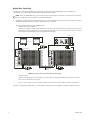
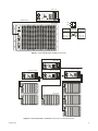
A single CM9770-MXB can support up to 256 camera inputs (in increments of 32) and 32 monitor outputs (in increments of 16). Refer to
Figure 12.
CM9700-CC1
CAM 17
CM9770 MXB
..................
CAM 1
MONITOR 1
MONITOR 32
CAM 256
Figure 12. Sample CM9770 System with 256 Cameras and 32 Monitors
C1555M-F (10/05)
21
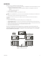
Multiple Bays, Single Node
In a single-node system with one CM9700-CC1 (not networked), you can connect multiple CM9770-MXBs using “sideframing” and
“downframing” for a maximum capacity of 2,048 camera inputs and 256 monitor outputs.
NOTE: When using CM9760-MDA units, you can increase the monitor output capacity to a maximum of 512. Refer to the Downframing
section in the Appendix for more information on using CM9760-MDA units.
•
Sideframing—To expand the matrix video inputs beyond 256, you can use multiple bays, with video from the monitor outputs on each bay
sideframed (with cable connections) to the bay to which the monitors are connected.
The System 9770 provides the following sideframing options:
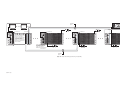
• Sideframe Option A (refer to Figure 13):
Sideframe from each bay to the bay to which the monitors are connected—the sideframe cables are connected to the video inputs on
the bay with the monitors, starting with slot one, and continuing to the higher slots as necessary. Any camera input slots not used to
receive output from sideframed bays can be used for additional camera inputs.
CM9700-CC1
MONITOR 1
MONITOR 32
TO CM9700-CC1
CAMERA 480
CAMERA 257
CAMERA 1
SIDEFRAME
CABLES
CAMERA 256
Figure 13. Sample System Using Sideframing from Bay to Bay
•
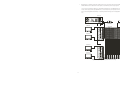
Sideframe Option B:
Sideframe from each bay directly to an output bay. This method requires an extra bay, but maintains the total capacity of camera
inputs in each of the other bays in the system.
Figure 14, on the next page, illustrates a sample sideframing system with all the sideframe cables connected to an output bay.
Refer to the Installing Additional Matrix Bays—Sideframing and Downframing section in the Appendix for detailed sideframing instructions.
22
C1555M-F (10/05)
CM9700-CC1
SIDEFRAME
CABLES
MONITOR 32
MONITOR 1
TO CM9700-CC1
TO CM9700-CC1
OUTPUT BAY
TO CM9700-CC1
CAMERA 257
CAMERA 1
OPTIONAL: ADD CM9770-VCC
INPUT CARDS AND BNC INPUT
CARDS AS NECESSARY TO
CONNECT SIDEFRAME CABLES
FROM ADDITIONAL BAYS OR
TO CONNECT CAMERAS
DIRECTLY TO THE OUTPUT BAY
(WHEN USING SEVEN MATRIX
BAYS OR FEWER)
ROUTE SIDEFRAME CABLES
FROM ADDITIONAL BAYS TO
NEXT AVAILABLE BNC INPUT
CARDS ON OUTPUT BAY.
CAMERA 512
MAXIMUM: EIGHT MATRIX BAYS
ONE OUTPUT BAY
CAMERA 256
SIDEFRAME
CABLES
Figure 14. Sample Sideframing System Using an Output Bay
C1555M-F (10/05)
23
•
Downframing—To expand the matrix video outputs beyond 32, you can loop the video from the first CM9770-MXB to subsequent
CM9770-MXB units for an additional 32 monitor outputs on each matrix bay. Refer to Figure Figure 15..
You can connect a maximum of eight bays in a downframing configuration for a total MXB capacity of 256 monitors; in addition, you can
increase monitor capacity further by using MDA units, for a total single-node system capacity of 512 monitors.
Refer to the Installing Additional Matrix Bays—Sideframing and Downframing section in the Appendix for detailed downframing instructions.
CM9700-CC1
CAMERA 256
MONITOR 1
CAMERA 1
CM9770-MXB
MONITOR 32
VIDEO
RIBBON
CABLES
MONITOR 33
MONITOR 64
CM9770-MXB
Figure 15. Sample Single-Node System with Downframing
24
C1555M-F (10/05)
Networked System
A networked system with multiple nodes uses an NIU (network interface unit) to combine up to 24 CM9700-CC1 systems into a network—each
CC1 system is called a “node.” Multiple CM9770-MXB units can be connected to each CC1 through sideframing and downframing. An NIU is a
CM9700-CC1 loaded with networking software, sold as a CM9700-NW1. Refer to Figure 16.
CM9700-NW1
CM9700-CC1 NODE 7
CM9700-CC1 NODE 6
TO NODE 7
CM9700-CC1 NODE 5
TO NODE 5
TO NODE 6
CM9770-MXB
CM9770-MXB
CM9770-MXB
Figure 16. Sample Networked System
C1555M-F (10/05)
25
THE POWER SUPPLY MODULE (CM9700-MPS)
You can add a backup power supply module (CM9700-MPS) to a System 9770 matrix bay to provide redundancy to the bay’s power supply.
NOTE: You can “hot swap” a backup power supply module—remove and/or insert a backup power supply—while the system is powered
and running.
INSTALL A BACKUP POWER SUPPLY
1. Open the matrix bay front cover.
2. Remove the blank-off plate from the empty power input slot.
3. Slide the power input module partially into the bay, on the guide rail.
4. Hold the latches parallel to the floor until you reach the edge of the bay’s frame.
5. Adjust the latches to fit them properly onto the top and bottom edges of the bay’s frame.
6. Push the latching levers into the closed position; this seats the power input module firmly into place.
7. Replace the matrix bay front cover.
REMOVE A BACKUP POWER SUPPLY
1. Open the matrix bay front cover.
2. Loosen the screw at the top of the power supply module.
3. Unlatch (pull) the levers at the top and bottom portion of the power supply module.
4. Pull the power supply module towards you (towards the front of the matrix bay) until it is out of the frame.
Figure 17. How to Install or Remove a Power Supply
26
C1555M-F (10/05)
HOW TO REPLACE THE FUSE IN A POWER SUPPLY MODULE
The matrix bay is shipped from the factory configured for the correct input power. The power input panel, on the rear panel of the matrix bay,
provides two separate power input receptacles, one for each power supply.
NOTE: The power input panel is not serviceable and should be removed or installed only by Pelco.
Each power input receptacle is equipped with a fuse assembly. In addition, each fuse assembly also provides a spare fuse. Refer to Figure 18.
WARNING: Always replace blown fuses with fuses of the same rating. Failure to do so could result in serious damage to the unit.
1. Remove the power cord from the power input receptacle.
2. Using a small screwdriver, pry the fuse holder out of the socket. The complete fuse assembly comes out of the unit.
3. Replace the fuse using a 1.6 ASB fuse. If using the spare, be sure to replace the spare with one of the same rating.
4. Plug the power cord into the power input receptacle.
REPLACE
IF NECESSARY
FUSE
HOLDER
SPARE FUSE
Figure 18. How to Replace a Power Supply Fuse
C1555M-F (10/05)
27
HOW TO TURN OFF THE AUDIBLE POWER SUPPLY ALARM
The power supply module contains an audible alarm, which operates in conjunction with the fault LEDs located on the power supply front panel.
To turn off this alarm, complete the following steps:
1. Turn off the matrix bay power.
2. Remove the power supply module from the matrix bay frame.
3. Move the speaker switch to the OFF position (refer to Figure 19).
4. Insert the power supply module back into the matrix bay frame.
5. Turn on the power.
SPKR ON/OFF
Figure 19. Power Supply Alarm Speaker Switch
28
C1555M-F (10/05)
SYSTEM DEVICE CONNECTIONS
1. Turn off power to all system devices and disconnect all power line cords while connecting system devices.
2. Complete the following steps to connect one or more CM9760-KBD system keyboards.
NOTE: CM9760-KBD software version 8.03 or higher is required.
a.
Connect the keyboard to the CM9505-UPS using the straight cable supplied with the keyboard.
b.
Connect the CM9505-UPS to one of the RS-422 COM ports on the CC1 using the 6-foot (1.8 m) reversed data cable supplied with the
keyboard. Refer to the RS-422 COM Port (“Sercom”) Connections section and your Port Assignments insert for directions on which
port to use for each keyboard.
c.
Refer to the CM9760-KBD Keyboard Installation/Operation manual for additional instructions on keyboard setup and operation.
CM9700-CC1
CM9700-CC1
RJ45-PIN-OUTS
PIN 1
PIN 2
PIN 7
PIN 8
=
=
=
=
TX+
TXRXRX+
CM9505-UPS
POWER SUPPLY
CM9760-KBD
CM9760-KBD
RJ-45 PIN-OUTS
PIN 1
PIN 2
PIN 7
PIN 8
=
=
=
=
TX+
TXRXRX+
Figure 20. Connect the CM9760-KBD to the CM9700-CC1
3. Connect a VGA monitor to the CM9700-CC1, as shown in Figure 21. This monitor displays the CC1 system diagnostic screen, as shown in
Figure 25.
4. Connect the PS/2 keyboard to the PS/2-to-AT keyboard adaptor, and then connect the adaptor to the CM9700-CC1, as shown in Figure 21.
5. Complete the following steps to connect a PC to the CM9700-CC1 (refer to Figure 21 and Figure 22):
a.
Using a null modem cable (user-supplied), plug one end into the DB9 COM 1 port on the PC.
b.
Plug the other end of the cable into the DB9 COM 1 port on the CC1, as shown in Figure 21. This port is configured at the factory for
use with the CM9700-MGR and RS-232 communication.
CM9700-MGR
VGA MONITOR
CM9700-CC1
PS/2 KEYBOARD
Figure 21. CM9700-CC1 Device Connections
C1555M-F (10/05)
29
CM9700-MGR
PC COM PORT
RS-232 CABLE
CM9700-CC1
COM 1/COM 2
PIN 3 (TX)
PIN 2 (RX)
PIN 2 (RX)
PIN 3 (TX)
PIN 5 (GND)
PIN 5 (GND)
DB9 FEMALE
DB9 FEMALE
Figure 22. CM9700-MGR PC Pin-Out Detail
6. Install any additional system peripheral devices. Refer to the manuals for the individual devices for instructions. Refer to the Data
Connections section and your Port Assignments table for directions on which port to use for each device.
7. Connect all power line cords to the equipment. Do not turn on the power until the installation is complete. Refer to the System Start-Up
section.
30
C1555M-F (10/05)
RS-422 COM PORT (“SERCOM”) CONNECTIONS
All peripheral equipment in a System 9770 connect through the RS-422 COM ports on the CM9700-CC1 rear panel. (These ports are also known
as “sercom” ports, short for “serial communication” ports.) If you exceed the number of CM9700-CC1 rear panel ports available, you can add
ports with the CM9700/9760-SER port expander unit.
NOTES:
•
When connecting peripheral equipment to the serial communication ports, shielded cabling is required to comply with CE
emissions guidelines.
•
Generally, Pelco will preconfigure your 9770 system, and then provide you with a Port Assignment Table. This document identifies
which port should be used for each device. Set up your system with the port assignments specified in your Port Assignment Table.
The information provided in this section should be used when expanding or servicing your system.
The 9700 System Manager software configures your system with the appropriate hierarchy of connections, so the easiest way to determine
where to connect each device is to use the 9700 System Manager to set up your system. The resulting list of devices in the tree view portion of
the CM9700-MGR Main window identifies the appropriate port number for each device in your system. Sample device list views are provided in
the following tables, to illustrate sample connections for each type of configuration.
Note that a specific hierarchy of connections is required when connecting equipment to the RS-422 COM ports. Connect MXB units into the first
available sequential ports, starting with port 5. Do not skip a port number when making MXB connections. Note, however, that the hierarchy
varies, depending on whether your system is networked and whether you use the hot switch package to connect a backup CC1 unit. The
hierarchy rules are provided in Tables B-E.
Once your MXB units and any NIU (network interface unit) or hot switch devices are connected (refer to Figure 23 and Figure 24), you can then
connect peripheral devices (such as keyboards) into any remaining ports. Peripheral devices do not have to be connected in any sequential order,
and you can leave ports empty between peripheral devices.
NOTE: In the following tables, “hot switch” refers to using the CM9760-HS hot switch package to connect a backup CC1, which provides
operational redundancy in a system. If the controlling CC1 unit were to fail, control would be passed to the backup CC1, and a system error
would be generated (through an LED and an audible tone). Refer to the System 9760 CM9760-HS Hot Switch Installation/Operation manual
for information on using a hot switch package. Note that the procedure for using a hot switch with a CM9700-CC1 is the same as for a
CM9760-CC1, except that the programming within CM9700-MGR is much easier. You just need to add the CM9760-HS as a device.
Table B. Data Connections—Single Node Systems Without a Hot Switch
MXB connection(s)
CC1 port 5 and next available sequential ports,
as necessary.
Other peripherals
Any available port(s)—these connections do
not have to be in sequential ports.
Table C. Data Connections—Networked System Without a Hot Switch
C1555M-F (10/05)
MXB connection(s)
CC1 port 6 and next available sequential ports,
as necessary.
NIU connection
CC1 port 5—note that this connection is made
through port 5 on each CC1 in the network.
Other peripherals
Any available port(s)—these connections do
not have to be in sequential ports.
31
Table D. Data Connections—Single Node, Hot-Switched System
MXB connection(s)
CC1 port 6 and next consecutive ports, as
necessary—connected through the hot
switch.
Hot Switch connection
CC1 port 5.
Other peripherals
Any available port(s)— connected through
the hot switch. These connections do not
have to be in sequential ports.
Table E. Data Connections—Networked, Hot-Switched System
MXB connection(s)
CC1 port 7 and next consecutive ports, as
necessary—connected through the hot
switch.
NIU connection
CC1 port 6—connected through the hot
switch.
Hot Switch connection
CC1 port 5.
Other peripherals
Any available port(s)— connected through
the hot switch. These connections do not
have to be in sequential ports.
NOTE: If you expand the number of matrix bay units in your system, you may need to change your port connections to connect each matrix
bay to the lowest sequential port possible. Refer to the How to Expand Your System section in the Appendix for more information.
32
C1555M-F (10/05)
CM9700-CC1
REVERSED CABLE
PIN 1
CM9770-MXB
PIN 8
CM9770-MXB
RJ-45 PIN-OUTS
REVERSED
DATA CABLE
PIN 1 = TX+
PIN 2 = TXPIN 7 = RXPIN 8 = RX+
CM9700-CC1
RJ-45 PIN-OUTS
PIN 1 = TX+
PIN 2 = TXPIN 7 = RXPIN 8 = RX+
Figure 23. Sample CM9770-MXB to CM9700-CC1 Connection
CM9700-NW1
CM9700-CC1 NODE 5
CM9700-CC1 NODE 7
CM9700-CC1 NODE 6
CM9770-MXB
CM9770-MXB
CM9770-MXB
Figure 24. Sample CM9770-MXB and CM9700-CC1 Connections in a Networked System
C1555M-F (10/05)
33
System Start-Up
To start up your system you must complete the following tasks:
1. Install the CM9700-MGR on a PC connected to the CC1.
Refer to System Device Connections in the Installation section for instructions on connecting a PC to the CC1. Refer to the CM9700-MGR
Software Guide for instructions on installing the CM9700-MGR software.
2. Complete the following steps on the CM9700-MGR PC (instructions are provided in the CM9700-MGR Software Guide):
a.
Copy the CM9700 system design file (the *.psm file) to the PC.
b.
Start the CM9700-MGR software.
c.
Open the system design file, and then customize the system as necessary. This step is optional because the *.psm file is defined at
the factory based on your system order.
OR
If your system order did not include the factory configuration process, your first step is to set up your system. Refer to How to
Configure a New System in the CM9700-MGR Software Guide for instructions.
3. Initialize the CC1. Refer to following section for instructions.
4. If you make any changes to the *.psm file, you must transfer the updated system settings to the CC1. Refer to Transferring System Settings
to the CC1 in the CM9700-MGR Software Guide for instructions.
INITIALIZE THE CC1
1. Apply power to all peripheral equipment connected to the CC1.
2. Apply power to the CC1.
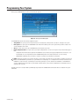
Initialization begins when the CC1 is turned on and the DOS boot process executes.
When the boot process calls the executable in the autoexec.bat file, the CC1 diagnostic screen appears on the VGA monitor. The
initialization process is complete when the message “Setup Complete” appears at the bottom of the screen.
Figure 25. CC1 Initialization
34
C1555M-F (10/05)
VERIFY SYSTEM OPERATION
1. Power up all the remaining equipment.
2. After the CM9700-CC1 loads the configuration files, “SYSTEM 97XX” appears on the CM9760-KBD LCD.
3. Enter the default operator password on the CM9760-KBD keypad. “ENTER MONITOR #” appears on the LCD.
NOTE: The default password for operator 1 is 0101; operator 2 is 0202; operator 3 is 0303; and so on. These numbers are defined in the
Operator PIN field in CM9700-MGR.
4. Enter 1, and then press the MON key. (Note: if you are not viewing monitor 1, substitute the appropriate monitor number.)
5. Enter a camera number, and then press the CAM key.
6. Press the FWD key to step through cameras and verify switching.
INITIALIZE KEYBOARDS
Specify a monitor for each keyboard after your first power-up or any time power is cycled to the keyboard or the CM9700-CC1.
Always allow five seconds to elapse before specifying a monitor.
1. Enter a number corresponding to the monitor output that is feeding the monitor you are viewing.
2. Press the MON key. The keyboard LED displays the number you entered. This also confirms successful communication between the
keyboard and the CM9700-CC1. If the keyboard LED does not display the monitor number, repeat steps 1 and 2.
C1555M-F (10/05)
35
DISPLAY THE CM9770-MXB SOFTWARE VERSION LEVEL
To display the software version level on a system monitor, complete the following steps:
1. Enter the monitor number, and then press the MON key.
2. Enter 999997, and then press the CAM key. The software version number appears on the monitor.
DISPLAY A BLUE RASTER SCREEN
To display a blue raster screen on a system monitor, complete the following steps:
1. Enter the monitor number, and then press the MON key.
2. Enter 999999, and then press the CAM key. A blue raster screen appears on the monitor.
MONITOR COLOR ADJUSTMENT
Once you have connected all devices and powered the system, you can use the System 9770 color bars as a reference tool for adjusting the color
on each monitor.
1. Enter the monitor number, and then press the MON key.
2. Enter 999998, and then press the CAM key. Broadcast quality color bars appear on the monitor.
BLACK
BLUE
RED
MAGENTA (LIGHT PURPLE)
GREEN
CYAN (LIGHT BLUE)
YELLOW
WHITE
3. Adjust color on each monitor as necessary until the color bars match the following color order on the monitor (for black and white monitors
you can use the color bars to adjust brightness).
Figure 26. System 9770 Color Bars
NOTE: You can also set DIP switches 5 and 6 on the monitor output card to display color bars. Refer to the Monitor Output Card
(CM9770-VMC) Detail section in the Appendix.
36
C1555M-F (10/05)
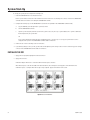
Programming Your System
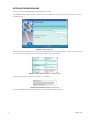
When you open CM9700-MGR, the Getting Started dialog box appears..
Figure 27. Getting Started Dialog Box
The CM9700-MGR provides the following configuration options:
•
Setup Wizard: This option opens the Setup Wizard (a series of dialog boxes), which provides assistance in setting up a new system.
•
New System: This option opens the CM9700-MGR main window with a blank system. Use this option when you want to create a new
system configuration from scratch.
•
Open: This option allows you to open a CM9700-MGR system design file (a .psm file).
•
Import Configuration Files: This option allows you to import configuration files. You can use this option to import the following types of
files:
–
Configuration files that have been copied from the CM9700-CC1 (note, however, that copying configuration files from the CC1 is not
recommended; the *.psm file generated from the CM9700-MGR provides more complete descriptions of system settings)
–
CM9760-MGR configuration files (also known as “flat files”) created for a System 9760 or System 9740.
NOTE: When Pelco customizes your system at the factory, system settings are saved in the *.psm file, which is provided to you on the CD
labeled “CD-CM9700CONFIG” (provided in your system binder). The accompanying sets of configuration files have been transferred to the
CM9700-CC1 at the factory. Any system changes should start by opening the *.psm file. (With previous CM9760-CC1 and CM9700-CC1
systems, configuration files were used for system changes. With the current system, however, configuration files are handled only as an
output from the *.psm file.)
Detailed instructions for using the 9700 System Manager are provided in the CM9700-MGR Software Guide which is included in the System
9770 binder.
C1555M-F (10/05)
37
GETTING HELP USING CM9700-MGR
Instructions for how to use CM9700-MGR are provided throughout the software.
The CM9700-MGR provides wizards to help users complete tasks, such as adding a device or a group. Each wizard screen contains instructions
and explanatory text.
Figure 28. Sample Wizard Page
When you are working within the grid view or tree view on the CM9700-MGR main window, help is provided as “real-time” help. When you click
on a row within the grid, the fields in that row are displayed in the properties area of the window.
Figure 29. CM9700-MGR Main Window - Properties Section
The box below the properties fields provides a description of the selected field.
Figure 30. CM9700-MGR Main Window - Help Section
Refer to the CM9700-MGR Software Guide (provided in the System 9770 binder) for detailed instructions.
38
C1555M-F (10/05)
Operation
A brief description of System 9770 operation is provided here.
Power-up the system.
Refer to the System Start-Up section.
Switch monitor.
Enter the monitor number.
Press the MON key.
Select camera.
Enter the camera number.
Press the CAM key.
Control PTZ receivers.
Use the appropriate PTZ control keys or joystick (depending on the keyboard used).
Call a preset.
Program the preset through the keyboard.
Enter the preset number.
Press the PRESET key or Prst/Lock key (depending on the keyboard used).
System does not function.
Refer to the Troubleshooting section.
OPERATING YOUR SYSTEM 9770
System 9770 can be operated with a CM9760-KBD or KBD300A keyboard. Operation instructions are provided below, but you should become
familiar with the detailed instructions provided in the appropriate keyboard manual.
Switch Monitors
If you select a restricted monitor, the monitor does not switch; the keyboard LED displays the previously selected monitor number.
1. Enter the monitor number.
2. Press the MON key. The keyboard LED displays the selected monitor number.
Select Cameras
If you select a restricted camera view, the camera view does not appear on that monitor. The previously selected, unrestricted camera view
remains on the monitor.
1. Enter the camera number.
2. Press the CAM key.
OR
Press the PREV or NEXT key to scroll through the available cameras.
Control Receivers
Select a suitable camera and operate a PTZ function.
Pan / Tilt / Zoom
Move the joystick until the camera reaches the desired position. To increase the speed of movement, move the joystick farther from center or
press the T key to pan at turbo speed. Twist the joystick clockwise to zoom in, counterclockwise to zoom out. Or use the IN/OUT key to zoom in or
out.
Lens Control: Focus, Iris
Use the NEAR/FAR key to focus near or far. Use the OPEN/CLS key to open or close the iris.
Call a Preset
1. Enter the preset number.
2. Press the Prst/Lock key, or select the PRST icon.
C1555M-F (10/05)
39
Appendix
SYSTEM ARCHITECTURE
The System 9770 is similar to Pelco’s System 9760 but uses different matrix bay hardware and provides more features. Users familiar with the
System 9760 should note the following differences:
•
Each System 9770 video input card (CM9770-VCC) receives input from 32 video connections (from the CM9770-RPC BNC input card, which
contains 32 BNC connectors). A fully loaded CM9770-MXB matrix bay supports 256 video inputs with just eight video input cards. Refer to
Figure 6 in the Installation section.
•
The CM9770-MXB provides slots for two monitor output cards (CM9770-VMC), providing a capacity of 32 monitors in a single bay. Refer to
Figure 11 in the Installation section.
•
When you “hot swap” video input cards (CM9770-VCC) or monitor output cards (CM9770-VMC), the CM9770-MXB automatically verifies
system software levels on all cards, and then updates software on the new cards if necessary.
•
The CM9700-MGR software provides the easiest way to configure your system. As you add devices or components to your system, it is
recommended that you first add them into the CM9700-MGR software. Then the software will reassign ports according to the appropriate
system hierarchy, and will easily renumber/rename system devices. Refer to the CM9700-MGR Software Guide for information.
NOTE: Actual maximum capacity depends on usage of the RS-422 COM ports on the CM9700-CC1. With the addition of CM9700-SER
serial communication cards and CM9700-SER-32 port expansion units, the number of RS-422 COM ports could be expanded to a maximum
of 120 ports. In addition, you would need to use COM ports to connect keyboards (and any other optional peripheral devices). Therefore, the
actual maximum number of cameras and monitors is restricted by the number of COM ports remaining available for the matrix bays, after
the number of COM ports needed for keyboards and other peripheral devices has been determined. If your system requirements exceed 120
ports, multiple 9770 systems can be networked together to reach your required capacity.
HOW TO EXPAND YOUR SYSTEM
The System 9770 provides a number of ways to expand your system to handle additional capacity. For example:
•
If you have a matrix bay that is not fully loaded, you can install additional video input cards (CM9770-VCC), up to a total of eight cards.
Refer to Installing Video Input Cards (CM9770-VCC) in the Installation section.
•
If you have a matrix bay with only one monitor output card (CM9770-VMC), you can install a secondary monitor output card in slot 9. Refer
to Installing Monitor Output Cards (CM9770-VMC) in the Installation section.
•
You can install additional matrix bay units in a single-node system, using either a sideframe configuration or a downframe configuration.
•
You can add a backup power supply module (CM9700-MPS) to a System 9770 matrix bay to provide redundancy to the bay’s power supply.
•
You can use CM9760-MDA unit(s) to increase monitor output capacity to a maximum of 512. Refer to the CM9760-MDA Installation/
Operation manual and note that the procedure for using an MDA unit with a CM9700-CC1 is the same as for a CM9760-CC1.
•
You can expand the number of communication ports available on the CC1 in either or both of the following ways:
–
If your original CC1 configuration allows, you can install additional CM9700-SER serial communication cards (the CC1 can contain a
maximum of four cards).
–
You can add additional, external communication ports with the CM9700-SER-32 Port Expander. Refer to the CM9700-SER-32 Port
Expander Installation/Operation manual and note that the procedure for using a port expander with a CM9700-CC1 is the same as for
a CM9760-CC1.
Instructions for expanding your System 9770 are provided in the following pages.
NOTE: You can also expand a single-node system to a networked system by adding a CM9700-NW1 unit. Refer to the Networking section
in this Appendix for instructions.
40
C1555M-F (10/05)
INSTALLING ADDITIONAL MATRIX BAYS—SIDEFRAMING AND DOWNFRAMING
When either more cameras and/or more monitors are needed than can be accommodated by one matrix bay (256 x 32), you can install additional
matrix bays in either of the following configurations:
•
Sideframing—This option increases the number of available video inputs.
•
Downframing—This option increases the number of monitors available for output.
Sideframing
To expand the matrix video inputs beyond 256, you can use multiple bays, with video from the monitor outputs on each bay sideframed (with
cable connections) to the bay to which the monitors are connected.
NOTE: Sideframing requires that the matrix bays be located in nearby bays since the expansion occurs in a horizontal manner.
In a sideframe configuration, the termination jumpers on the RPC cards must be set as follows:
•
The input bay(s) termination jumpers must be in the unterminated position; these are the bays to which the cameras (or other input devices)
are connected.
•
The output bay termination jumpers must be in the terminated position; these are the bays to which the monitors (or other output devices)
are connected.
Refer to Change the Termination Jumpers on a Rear Panel Video BNC Cardin the Installation section for instructions.
The System 9770 provides the following sideframing options:
•
Sideframe Option A (refer to Figure 13 in the Installation section):
Sideframe from each bay to the bay to which the monitors are connected—the sideframe cables are connected to the video inputs on the
bay with the monitors, starting with slot one, and continuing to the higher slots as necessary. Any camera input slots not used to receive
output from sideframed bays can be used for additional camera inputs.
Note that the bay-to-bay input-to-output wiring must correspond to specific slot positions, as illustrated in Figure 13 and Figure 14 in the
Installation section.
•
Sideframe Option B (refer to Figure 14 in the Installation section):
Sideframe from each bay directly to an output bay. This method requires an extra bay, but maintains the total capacity of camera inputs in
each of the other bays in the system.
C1555M-F (10/05)
41
Downframing
To expand the matrix video outputs beyond 32, you can downframe the video from the first CM9770-MXB to subsequent CM9770-MXB units for
an additional 32 monitor outputs on each matrix bay. Refer to Figure 31.
You can connect a maximum of eight bays in a downframing configuration for a total MXB capacity of 256 monitors; in addition, you can increase
monitor capacity further by using MDA units, for a total single-node system capacity of 512 monitors.
When downframing video, the termination jumpers on the RPC cards in the first bay must be set in the unterminated position. Refer to Change
the Termination Jumpers on a Rear Panel Video BNC Cardin the Installation section for instructions.
When looping video out to another device (such as a DVR, VCR, or switcher), use the CM9770-DFL card in the final bay. You must set the
termination jumpers on the CM9770-DFL card to the unterminated position. Refer to the Change the Termination Jumpers on a Rear Panel Video
BNC Card section. Terminate the video signal at the final device.
42
C1555M-F (10/05)
Refer to the Downframing section on the following page for instructions on setting the termination jumpers in the downframed bays.
Figure 31. Downframing with DFC Cards
C1555M-F (10/05)
Figure 32. Looping Video Out in a Downframed Configuration
43
A downframe cable is used to connect the bottom connector of the RPC card to a downframe card.
Figure 33. DFC Cable
Downframe Cards
The following downframe cards are available for the System 9770:
•
CM9770-DFC—This is the “no looping” downframe card.
•
CM9770-DFL—This is the “looping” downframe card.
If you are downframing to only one bay, the downframed bay can be populated with either DFL or DFC cards.
If you are downframing to more than one bay, each bay between the first and the last must be populated with DFC cards, and the termination
jumpers must be set in the unterminated position. The last bay can be populated with either DFL or DFC cards. You must terminate the video
signal at the final point in the downframe configuration, which could be either of the following:
44
•
If you are not looping video out from the final bay, terminate the video at the DFL or DFC cards in the final bay.
•
If you are using the DFL card in the final bay, and are looping video to another device, terminate the video signal at the final device.
C1555M-F (10/05)
TERMINATED
UNTERMINATED
INPUT FROM BAY ABOVE
(LOWER-NUMBERED SLOT)
JP16
JP15
JP14
JP13
JP12
JP11
32 1
JP10
JP9
JP8
JP7
JP6
JP5
JP4
JP3
JP2
JP1
OUTPUT TO BAY BELOW
(LOWER-NUMBERED SLOT)
UNTERMINATED
TERMINATED
INPUT FROM BAY ABOVE
(HIGHER-NUMBERED SLOT)
JP32
JP31
JP30
JP29
JP28
JP27
JP26
JP25
JP24
JP23
JP22
JP21
JP20
JP19
JP18
JP17
OUTPUT TO BAY BELOW
(HIGHER-NUMBERED SLOT)
Figure 34. DFC Card
Figure 35. CM9770-DFL Card
C1555M-F (10/05)
45
HOW TO INSTALL OR REPLACE A CM9700-SER CARD IN THE CC1
If you have ordered a replacement or additional CM9700-SER serial communication card, complete the following steps to configure the jumpers
on the CC1 board for the slot position the new SER card will occupy.
NOTE: When connecting peripheral equipment to the serial communication ports, shielded cabling is required to comply with CE
emissions guidelines.
1. Turn off the CC1 power switch.
WARNING: Failure to turn off the CC1 power switch could result in serious damage to the equipment.
2. Remove the top cover of the CC1. Refer to Figure 36.
a.
Remove the 10 screws that hold the top cover in place.
b.
Tilt the top cover up at a slight angle, as indicated by the dotted line in the drawing, and then pull the cover backwards to remove the
cover from the front edge of the CC1 chassis.
Figure 36. Removing the CC1 Top Cover
3. Set the W1 interrupt (IRQ) and W2 address select jumpers on the SER card. Refer to Figure 37.
Note that the jumper settings vary, depending on the ISA slot in which the SER card is to be installed. Refer to the following tables for a list of
SER card jumper assignments.
Table F. SER Card Jumper Assignments for a CM9700-CC1 System Control
ISA Slot Number
W1 IRQ Setting
W2 Address Setting
1
IRQ 10
Pins 1 to 2 and 3 to 4
2
IRQ 11
Pins 1 to 2 only
3
IRQ 12
Pins 3 to 4 only
4
IRQ 5
No jumpers
Table G. SER Card Jumper Assignments for a CM9700-NW1 Network Interface Unit
ISA Slot Number
W1 IRQ Setting
W2 Address Setting
1
IRQ 10
Pins 1 to 2 and 3 to 4
2
IRQ 11
Pins 1 to 2 only
3
IRQ 12
Pins 3 to 4 only
NOTE: For a CM9700-NW1, the default configuration is one SER card. A maximum of three SER cards can be installed in a CM9700-NW1.
46
C1555M-F (10/05)
W1 IRQ SELECT
IRQ 15
IRQ 14
IRQ 12
IRQ 10
IRQ 11
IRQ 7
IRQ 9
IRQ 5
IRQ 6
PIN 21
IRQ 4
PIN 22
PIN 1
IRQ 3
PIN 2
W2 ADDRESS
SELECT
PIN 2
PIN 4
PIN 1
PIN 3
Figure 37. SER Card Jumper Assignments
4. Insert the new SER card into an available ISA slot. The default CM9700-CC1 configuration provides SER cards in ISA slots 1 and 2, so you
will most likely insert the new card into slot 3 or 4. Refer to Figure 38.
5. Replace the top cover of the CC1.
6. Power up the CC1.
CM9700-SER CARD
ACCESS SLOTS
(SLOT COVERS
REMOVED)
SLOT
COVERS
ISA SLOTS (DEFAULT
CM9700-SER CARDS SUPPLIED
IN ISA SLOTS 1 AND 2)
CM9700-CC1 CHASSIS, FRONT
Figure 38. How to Install a CM9700-SER Card
C1555M-F (10/05)
47
VIDEO INPUT CARD (CM9770-VCC) DETAIL
VSYNC
OFF ON
GREEN
AMBER
RED
AMBER
Figure 39. CM9770-VCC Card
Table H. Video Input Card (CM9770-VCC) LEDs
48
Front Panel Label
Color
When LED Is On
+
Green
The +5 VDC power source is functioning properly.
-
Green
The -5 VDC power source is functioning properly.
HB
Amber
The CPU is active; this “heartbeat” LED blinks at a different rate, according to the current activity:
0.25 Second: Programming
The VCC card blinks at a quarter-second rate while it receives updated programming from the primary VMC card.
0.5 Second: Boot ROM
The VCC card blinks at a half-second rate while executing boot ROM code.
1.0 Second: Normal Operation
The VCC card blinks at a one-second rate during normal operation.
CF
Red
This LED illuminates if communication from the primary CM9770-VMC monitor card failed or if the CM9770-VMC
card is inserted in the wrong slot.
VL
Red
Video Loss: This LED illuminates when there is a video signal missing from the input of the rear panel.
CD
Amber
Configuration: This LED illuminates on startup if the FPGA is not programmed. Once the FPGA is programmed from
the application code or the test code, it will turn OFF.
AX
Amber
This LED toggles on every valid switch command. It also flashes when the CF LED is illuminated to indicate that
communication with the primary CM9770-VMC card failed.
C1555M-F (10/05)
MONITOR OUTPUT CARD (CM9770-VMC) DETAIL
DIP SWITCH
GREEN
AMBER
Figure 40. CM9770-VMC Card
Table I. Monitor Output Card (CM9770-VMC) LEDs
Front Panel Label
Color
When LED is on or blinking
+
Green
The +5 VDC power source is functioning properly.
-
Green
The -5 VDC power source is functioning properly.
HB
Amber
The CPU is active; this “heartbeat” LED blinks at a different rate, according to the current activity:
Primary VMC—0.25 Second: Downloading
The primary VMC card blinks at a quarter-second rate while updated software is downloading from a PC connected to
the RS-232 COM port on the rear panel.
Secondary VMC—0.25 Second: Receiving
The secondary VMC card blinks at a quarter-second rate when it is receiving files from the primary VMC card.
0.5 Second: Boot ROM
The primary and secondary VMC cards blink at a half-second rate when in normal boot ROM mode.
1.0 Second: Normal Operation
The primary and secondary VMC cards blink at a one-second rate during normal operation.
RX
Amber
Blinks when communication is active between the MXB and either the CC1 or a PC (through the RS-232 COM port; for
system software upgrade).
MP
Amber
Blinks when communication is active between the primary VMC card and the other cards (secondary VMC card and
VCC cards). This communication occurs during normal system operation, as switching commands are sent and polled.
FP
Amber
Blinks once to indicate that the characters have been enabled for monitor display. This is the third initialization step.
CP
Amber
Blinks once to indicate that the CPU support chip has been configured. This is the second initialization step.
BP
Amber
Turns on during the boot sequence (the first initialization step), and turns off when initialization is complete.
C1555M-F (10/05)
49
The monitor output card DIP switch selects various options. These switches are set in the proper position at the factory, but they can be changed,
if necessary.
Table J. Monitor Output Card DIP Switch
Switch 1
ON
OFF
Color System
PAL
NTSC
Switch 3 Switch 2
OFF
OFF
ON
OFF
OFF
ON
ON
ON
Port 1 RS-422 Baud Rate
9600
19200*
57600
115200
Switch 4
ON
OFF
Data Protection
Main flash programmable
Main flash protected*
Switch 5 Switch 6
OFF
OFF
ON
OFF
OFF
ON
ON
ON
Test Mode
Not used*
Diagnostic mode
Display software version levels
Display color bars
NOTE: You can also display color bars with a keyboard command (refer to Monitor Color Adjustment in the System
Start-Up section).
Switch 7
ON
OFF
Video Loss
Report
Ignore*
Switch 8
ON
OFF
Primary VMC Program All Hardware
Force
Upload if necessary*
The primary CM9770-VMC card verifies the version levels on all software and hardware image binary files on the
secondary CM9770-VMC card and the CM9770-VCC cards. If the file versions levels are not the same as the files on
the primary CM9770-VMC, the primary CM9770-VMC updates all the files on the secondary CM9770-VMC card and
the CM9770-VCC cards.
If you change this setting to Force, the primary CM9770-VMC updates all the files on the secondary CM9770-VMC
card and the CM9770-VCC cards without checking file version levels.
*Factory settings
50
C1555M-F (10/05)
NETWORKING
Networking of systems is required when the following conditions apply:
•
Two or more individual systems need to share video and control features. The CM9700-NW1 network interface unit (NIU) allows you to link
any combination of the following systems into a network:
–
One or more System 9740 or 9760 systems (note that the CM9740-CC1/CM9760-CC1 must be upgraded to software version
level 9.01)
–
One or more System 9770 or 9780 systems
•
More than 2,048 cameras are required.
•
More than 256 monitors are needed for the system (without full cross-point).
NOTE: When using CM9760-MDA units, you can increase the monitor output capacity of a non-networked system to a maximum of 512.
•
Alarms and cameras connected to remotely-located systems need to be accessed.
The CM9700-NW1 network interface unit allows you to combine your systems into a network. Up to 24 nodes can be connected to a
CM9700-NW1.
The NIU offers the following features:
•
Each system maintains local operations (local camera switching, control, etc.) if the NIU goes off-line.
•
A system can be remotely located as far as the transmission type and path allows (typically hard-wired with 24 AWG twisted pair up to a
maximum of 4,000 feet/1,219 m).
•
Information on each node connected to the network (for example, cameras and monitors attached) is automatically downloaded to the NIU.
•
Operators can be allocated/restricted access to most features/equipment throughout the network.
•
Alarm signals can be transferred between nodes.
Refer to the System 9760/9770 Networking Guide for detailed instructions on networking your system. Note that the information in the
networking guide is applicable to both the System 9760 and the System 9770, except for the instructions in the Network Setup section, which
apply to the old CM9760-MGR software. For instructions on programming a system controlled by a CM9700-NW1, refer to the CM9700-MGR
Software Guide (provided in the System 9770 binder).
CM9700-NW1
DATA
RS-422
VIDEO
CM9700-CC1 NODE 6
CM9700-CC1 NODE 5
RS-422
OUTPUT
INPUT
OUTPUT
INPUT
VIDEO TIE
LINES
Figure 41. Sample Networked System
C1555M-F (10/05)
51
CONNECTING SATELLITE DEVICES
You can connect a CM6800E-48X8 matrix switcher or a CM9760-SAT device to the System 9770.
Refer to the CM9760-SAT Installation/Operation manual or to the CM6800E-48X8 Installation/Operation manual for instructions. The procedure
for using a satellite device with a CM9700-CC1 is the same as for a CM9760-CC1, except that the programming within CM9700-MGR is more
user-friendly. You just need to add the satellite device using the Add Device wizard. The wizard leads you through the process, which includes
selecting tie lines and unique logical numbers.
REMOTE SITE
LOCAL SITE
CM6800E-48X8
CM6800E-48X8
CPU
1-48 CAMERAS
RS-422
DATA
LINE
MATRIX
BAY
CM6800E-48X8
VIDEO TIE
LINES
KBD300A
CM9770
CM9760-KBD
Figure 42. Sample Satellite System
PROGRAMMING SATELLITE DEVICES
To add a satellite device to a System 9770, you simply need to add the satellite device in the CM9700-MGR. The Add Device wizard helps you
configure all the settings that are needed to set up the device for satellite operation.
Detailed instructions for adding a satellite device in the CM9700-MGR are provided in the CM9700-MGR Software Guide.
Note that you cannot program camera titles for satellite cameras through the 9700 System Manager. You can program these camera titles
directly from the satellite device. When a System 9770 monitor displays a satellite camera, the title received from the satellite device is
displayed.
Figure 43. Add a Satellite Device
52
C1555M-F (10/05)
HOW TO INSTALL VIDEO PATCH PANELS (CM9700-VPP)
There are two ways you can mount a CM9700-VPP video patch panel into a rack.
1. Single panels onto a rack
2. Up to 16 panels using the CM9700-VPP-RK
The following illustration shows how to mount a single panel onto a rack. The panel is mounted horizontally.
RACK
CABLE
BRACKET
CM9700-VPP
(4) SCREWS, 10-32X3, PHILLIPS
PANHEAD WITH WASHERS
RACK
MOUNT
BRACKET
Figure 44. CM9700-VPP Horizontal Mount
The following illustration shows how to mount up to 16 panels using the CM9700-VPP-RK. The panels are mounted vertically in the
CM9700-VPP-RK. This rack saves 1 RU of space and provides better cable management.
THUMBSCREW
RACK
CM9700-VPP
(MAXIMUM OF 16)
THUMBSCREW
CM9700-VPP-RK
(8) SCREWS, 10-32X3, PHILLIPS
PANHEAD WITH WASHERS (4 EACH SIDE)
Figure 45. CM9700-VPP Vertical Mount
C1555M-F (10/05)
53
MOUNTING THE CM9770-MXB IN AN OPEN RACK
Figure 46. Mounting the CM9770-MXB in an Open Rack
54
C1555M-F (10/05)
DOS ENVIRONMENT AND COMMAND REFERENCE
DOS stands for Disk Operating System. Every time you turn on the CM9700-CC1 or every time you reboot (Alt +Ctrl +Del), the computer loads DOS
from the CC1 disk into the memory (RAM). Once loaded DOS lets you run other programs, in particular, the CM9700.EXE program.
On factory-configured systems the autoexec.bat file is configured for one of the following scenarios:
•
The boot process ends at the following system prompt (c:\9700>).
•
The boot process loads and executes the CM9700.EXE program.
THE BOOT PROCESS
The following process occurs when the CC1 is turned on or is rebooted:
1. If turned OFF and then turned ON, the CC1 goes through a power-on self-test (POST). Here the computer essentially examines its electronic
components.
2. The computer looks at drive A for a DOS system disk. If one is not there, the CC1 will load DOS from its hard drive.
3. This process looks for two “hidden” system files: IO.SYS and MSDOS.SYS. If these files are not present, DOS displays the “Non-System
disk or disk error” message. (The CC1 also displays this error during the boot process if there is a floppy disk in the A drive that has no
system files).
4. If the “hidden” files are present, IO.SYS loads first and executes. An initialization program called SYSINIT contained within IO.SYS reads in
the MSDOS.SYS file; SYSINIT next locates the CONFIG.SYS file and executes its files for it to configure itself in memory. Then, SYSINIT
locates and invokes COMMAND.COM. If SYSINIT cannot find COMMAND.COM, DOS displays the “Bad or missing Command Interpreter“
error message.
NOTE: Since COMMAND.COM is not a hidden file, it is possible that it could accidentally be moved, corrupted or erased. If this occurs, you
may need to start DOS from a floppy disk and COPY COMMAND.COM into the CC1s root directory.
5. If SYSINIT finds and loads COMMAND.COM, it, in turn, searches your root directory for the AUTOEXEC.BAT file. If it exits,
COMMAND.COM will cause the AUTOEXEC.BAT file to execute. If AUTOEXEC.BAT does not exist, the DATE and TIME commands are
invoked by COMMAND.COM. After entering date and time information, the basic system prompt (C:>) appears. This completes the startup
or boot process.
You cannot separate the boot process from CC1 initialization. The DOS boot process must succeed before the CM9700.EXE program can run. The
result of the DOS initialization process is that you either have a system prompt on a DOS screen or, as part of the boot process, the CM9700.EXE
program has been invoked. In the latter case, the System window of the diagnostic screen displays “Setup Complete…” if everything initialized
OK; otherwise, an applicable error message appears.
AUTOEXEC.BAT AND THE BOOT PROCESS
The AUTOEXEC.BAT file is the last file called during the boot process. For CC1s configured as part of a system node at the factory, the end result
of this process is the appearance of the CM9700 diagnostic screen on the attached VGA monitor.
The factory-configured boot process occurs because of the instructions added to the AUTOEXEC.BAT file. The AUTOEXEC.BAT file is a batch file,
which contains a series of instructions that are executed serially when the file is called.
Invoking the CM9700 Executable
The following commands are the last two in the AUTOEXEC.BAT file:
CD9700
This command directs DOS to the 9700 directory where the 9700 executable resides.
CM9700 Node1
This command starts the executable (CM9700) and directs the program to load into memory all configuration files having the
collective prefix name of “Node1” (also located in the same directory).
The program continues to configure the system environment and goes on line. If everything is functioning properly, the “Setup Complete”
message appears on the CM9700 diagnostic System Window on the attached VGA monitor.
If you change the name (the prefix) of your current flat files or copy a new set of configuration files (with a different name) to the 9700 directory,
then you must change the AUTOEXEC.BAT file to correspond.
C1555M-F (10/05)
55
File Names and DOS
File names in DOS are limited to eight characters. If you issue a command to change the name of the configuration files in the 9700 directory to a
name exceeding eight characters, the name is truncated to eight characters. The Windows-based CM9700-MGR program does not allow you to
use more than eight alphanumeric characters when creating a name for your set of configuration files.
DOS Commands
DOS commands are divided into two groups. Because of the large number of DOS commands available, only the most commonly used commands
are loaded into memory (RAM). The remaining commands reside in the DOS directory. The commands loaded into memory are called internal
commands and the commands in the DOS directory are called external commands. When DOS reads a command, it looks first in RAM, then it
looks in the DOS directory, and then it looks in the directory from which the command was issued. If you invoke an executable type file that isn’t
in any one of those places, you must navigate to the directory in which the executable file is located.
The Path Statement
As an alternative to navigating to the directory in which an executable file is located, you can put a PATH command statement into the
AUTOEXEC.BAT file. The PATH statement directs DOS to look in each of the directory paths listed there for any executable [.EXE, .COM or .BAT
file] it is instructed to carry out. The syntax of the PATH statement is as follows:
PATH = { [drive:]path; [drive:]path; [drive:]path…..] }
Example: PATH=c:\;c:\dos;c:\windows
(Note that spacing is included in the syntax statement to make it easier to see the elements that make up the path statement. In actual use,
no spaces exist, as demonstrated in the example.)
Semicolons (;) separate drive-path statements. There are no spaces. The complete drive path must be given for each directory you wish to
include in the search. The search is for files with .EXE and .COM extensions only. If the executable you call, in turn, issues a call for a nonexecutable file (that is, one without an .exe or .com extensions), then the PATH statement does not apply. Instructions for using the executable
must tell you either where to place needed non-executable files or the executable itself must provide the means whereby the file can be found.
DOS will not look for these files.
Note that you cannot insert the directory path for the CM9700 executable file into the PATH statement. The CM9700 executable uses a nonexecutable file that always resides in the C:\9700 directory. If you invoked the CM9700 executable from any directory location other than the
C:\9700 directory, the executable would not finish successfully because CM9700.EXE expects to find the file residing in the same directory that it
does. You can manually invoke the command (CM9700 test) while in the C:\9700 directory, but in most cases, you need to reboot the CPU, and as
a result, DOS boots to the root directory. That is why the CD command to switch to the 9700 directory is included in the AUTOEXEC.BAT file. If
you used the PATH command statement alone, the CM9700.EXE would be found, but the other non-executable file needed would not be found
and system initialization would fail.
Navigating the DOS Directory Tree
When you exit to DOS on the CC1, you are normally at the C:\9700> screen prompt. While in the directory, you may manipulate any file there or
you may navigate to any subdirectory contained in that directory.
To navigate to a subdirectory of the 9700 directory, use the following syntax:
C:\9700> CD [subdirectory name] [ENTER]
For example, if a 9700 subdirectory had the name BKUPTST, your entry would read as follows:
C:\9700> CD BKUPTST [ENTER]
This takes you to the C:\9700\BKUPTST> screen prompt in the BKUPTST directory:
Once in the C:\9700\BKUPTST> prompt, files within the directory can be manipulated. The key entries used to backtrack up the directory tree
depend on where you want to go. From the BKUPTST directory, you either can go back to the root directory with one single key entry or you can
go in steps, one directory at a time. To proceed directly to the root directory, enter the following:
C:\9700\BKUPTST> CD\ [ENTER]
The “ \ ” symbol, when used alone represents the root directory; otherwise, it indicates separation of various levels of the directory tree,
collectively known as the directory path. The result of the above entry takes you directly to the root directory and the “C:\>” screen prompt:
To backtrack up the directory tree one directory at a time, enter the following at the system prompt:
C:\9700\BKUPTST> CD.. [ENTER]
That entry takes you to the C:\9700> prompt.
56
C1555M-F (10/05)
If you entered the same command again (CD..) at the c:\9700> prompt and pressed the ENTER key, you would finally end up again at the root
directory as previously done. To proceed directly from the directory you are in to another directory, no matter where in the directory tree you are,
enter the total directory path of the location you wish to go to at the system prompt.
For example, to get to the C:\9700\BKUPTST directory from the root directory, type C:\> CD [directory path], and then press the ENTER key. You
will be at the C:\9700\BKUPTST> screen prompt.
Manipulating Files in the DOS Environment
The safest way to manipulate files is to do so from within the directory in which those files are located. This is because of the following reasons:
•
If you enter a DIR command at the directory prompt, then the names of the file(s) you wish to manipulate are right there on the screen. This
reduces the risk of making simple mistakes, such as entering an incorrect file name as part of an erase command, for example.
•
When using commands directed at file manipulation, the format of the command requires that the command name be listed first, followed
by the file name to be acted upon. If you issue a command for a file that is in another directory, then you must enter the complete directory
path where that file is found in addition to the name of the file at which the command is directed.
The command formats (such as COPY, MOVE, RENAME, DELETE) for the most commonly used commands are provided with examples in the
Command Reference Table at the end of this section.
Using the Wild Card Character
The most commonly used wild card character recognized by DOS is the asterisk (*). The asterisk can be used as a placeholder to group files that
are going to be acted upon by the same DOS command. The asterisk helps you specify character positions that are of the “don’t care” type in file
names. When DOS encounters the asterisk, DOS ignores the characters in the position containing the wildcard as well as all the characters that
follow it.
The CM9700-CC1 configuration files provide a good example of how the wildcard can be used.
Example 1
To copy configuration files from the A floppy drive to the 9700 directory on the CC1 disk complete the following steps:
1. Change to the A: directory
2. At the A prompt type your command using the following syntax:
A:> copy [configuration file name].* [destination].
For example, if the filename prefix for the configuration files was “Node1”, type copy Node1.* C:\9700
3. Press the Enter key.
Example 2
To move configuration files from the 9700 directory to another directory [previously created] for archiving purposes, complete the following steps:
1. Change to the 9700 directory.
2. Type your command using the following syntax:
C:\9700>copy [source] [destination]
For example, if the destination directory was “archive,” type copy Node1.* C:\archive
Since you are already in the 9700 directory, the source portion of the command consists only of the file name(s) to be moved. The
destination contains the path to the directory where the files are to be moved to.)
3. Press the Enter key.
C1555M-F (10/05)
57
DOS REFERENCE
The following table provides a list of the most common DOS commands that you are most likely to use when operating the CC1. In addition, you
can use the command HELP to access the MS-DOS command reference on the CC1.
NOTE: In DOS, the backslash symbol (“ \ “) used alone, refers to the root directory. The [..] symbol refers to the parent directory.
Table K. DOS Command Reference Directory
COMMAND
EXAMPLE(S)
CD
C:\>CD
Displays the name of the current directory or changes the current
directory if specified and if the directory specified exists.
C:\>CD 9700
Changes to the 9700 directory.
CLS
C:\>CLS
The Clear Screen command clears a full screen to just the
command prompt and the cursor.
COPY
C:\>COPY [source] [destination]
C:\>COPY A:\TEST.* C:\9700
C:\>COPY A:\*.* C:\9700
C:\>COPY A:\TEST.MON C:\9700
Copies one or more files to the location you specify. Source
specifies the location and name of a file or set of files. Source can
consist of a driver letter and colon, a directory name, a filename, or
a combination files you wish to copy. Destination specifies the
name and location of a file or set of files to which you want to copy.
Destination can consist of a drive letter and colon, a directory
name, a filename, or a combination. When more than one file is
copied, MS-DOS displays each filename as the file is copied.
DEL
C:\>DEL C:\9700\TEST.MON
C:\>DEL A:TEST.MON
C:\9700>DEL TEST.*
Deletes the file or files you specify. You must include the location
(if other than you current location) and name of the file or set of
files you wish to delete.
C:\9700>DEL TEST.* /P
DIR
EDIT
SWITCHES
/P
C:\>DIR
COMMENTS
Prompts you for confirmation before deleting each file.
Displays a list of files and subdirectories that are in the directory
you specify. When you use the DIR command without switches, it
displays the disk’s volume label and serial number, one directory or
filename per line including the filename extension, size, date and
time file was last modified; total number of files listed, cumulative
size and free space left on the disk.
C:\>DIR/W
/W
Displays the listing in wide format, with as many a five filenames
or directory names on each line.
C:\>DIR/P
C:\>DIR/W/P
/P
Displays one screen of the listing (in whatever format) at a time. It
is useful to use these switches when looking at the contents of the
DOS directory.
This switch will look for all instances of the filename in all
directories.
C:\ >DIR { filename} /S [syntax]
example: C:\ >DIR *.mon /S
/S
In the example the location of all file names having the .mon
extension will be found and displayed.
C:\>EDIT AUTOEXEC.BAT
Starts the MS-DOS editor, a test editor you can use to create and
edit ASCII text files. The example text shown would load the
autoexec.bat file for editing.
(Continued on next page)
58
C1555M-F (10/05)
COMMAND
EXAMPLE(S)
FASTHELP
C:\>FASTHELP
Lists and briefly describes every command provided with MS-DOS.
This list is much less detailed than the list you get using the
“HELP” command.
C:\>FASTHELP DIR
Specifies the name of the command that you wish FASTHELP to
give information about. In this example, DIR.
C:\>FORMAT A:
Formats a disk for use with MS-DOS.
FORMAT
C:\>FORMAT A:/S
HELP
SWITCHES
/S
COMMENTS
Transfers system files to the formatted disk. You can boot from the
floppy of a disk formatted using this switch.
C:\>HELP
Starts the MS-DOS command reference located on the CC1’s hard
disk.
C:\>HELP DIR
Specifies the command whose help topic you want to display. In
this example, DIR.
MD
C:\>MD 9700
Creates a directory. The example creates a 9700 directory.
MORE
C:\>DIR C:\DOS | MORE
Displays one screen of information at a time. Can also be used
with the TYPE command when viewing a long text file. The symbol
is called a redirection operator. On the keyboard, it is located
above the backslash \ symbol.
PATH
Indicates which directories DOS should search for executable files.
By default, DOS searchers just the current directory.
RENAME or
REN
C:\>RENAME C:\9700\TEST.*
TESTALL.*
C:\>REN C:\9700\TEST.* TESTALL.*
Changes the name of the file or files you specify. Specify the name
and location of the file or files to be changed. The last part of the
command specifies the new name. You cannot specify a new drive
or path.
TYPE1
C:\>TYPE C:\9700\TEST.MON
Displays the contents of the text file you specify. You must specify
a directory path if the location of the file is in a directory other than
the one you are in.
C:\>TYPE C:\9700\TEST.ALM
MORE
UNDELETE
| MORE
C:\>UNDELETE C:\9700\TEST.BAT
Here the MORE redirection operator is used to enable us to view
the alarm file (usually quite long), one page at a time.
Restores files that were previously deleted using the DEL
command.
C:\>UNDELETE C:\9700\ /LIST
/LIST
Lists the deleted files that are available to be recovered, but does
not recover any files.
C:\>UNDELETE C:\9700\ /ALL
/ALL
Recovers deleted files without prompting for confirmation on each
file.
RMDIR or
RD
C:\>RMDIR NETWORK
C:\>RD NETWORK
Deletes or removes a directory. Before the directory can be
deleted, it must contain no files or other subdirectories. The
directory must be completely empty except for the “ . ” and “ . . ”
symbols.
VER
C:\>VER
Displays the current version of DOS on your machine.
TREE
C:\>TREE
Displays the directory structure of all the directories on your hard
drive if it is issued while in the root directory; otherwise, it will
display only the subdirectories of the directory you are currently in.
C1555M-F (10/05)
59
Troubleshooting
Problems with the CC1
Problems with the CC1 as part of a 9770 system may occur in the following areas:
•
The CC1 itself
•
Setup files (also known as configuration files)
•
Peripheral devices connected to the CC1
•
DOS operating system
A log is recommended for keeping track of changes made to the system. The log should document the change made, why it was made, the date
it was made, and the person responsible for the change. This log will help in troubleshooting any errors that may occur. It also makes it easier to
identify errors that might have been caused by the change from other types of errors.
Table L. CC1 Hardware Errors
Symptom
Possible Cause
Corrective Action
Green power LED not lit.
No AC power to the unit.
Check power cord connection.
Fuse has blown.
Replace fuse.
No VGA display.
Video cable not seated.
Power cord not plugged in.
Bad VGA card.
Table M. CC1 System Errors
Symptom
Possible Cause
Corrective Action
Port x ERR Coms Framing
Mismatched baud rate settings.
Correct the baud rate setting in the CM9700-MGR to match
the settings in the device connected to the specified port.
Port x ERR Coms Fatal
Failure of Comms line after power up and initialization.
Check and correct hardware fault.
Port x ERR Coms Parity
Mismatched parity settings.
Correct the parity setting in the CM9700-MGR to match the
settings in the device connected to the specified port.
Port x ERR Coms Max Retry
If the communications line is faulty (wired incorrectly or not
seated properly), the diagnostic screen displays this error
message during initial power-up. If the communication line
goes bad after power-up and initialization, then a Port x ERR
Coms Fatal error appears, followed by a Port x ERR Max
Retry message.
Check and correct the hardware fault.
Temporary communications fault.
Fault will automatically be corrected when communications
resume.
Noise on the data line.
Check data cables.
The VCC Card CF LED Is Illuminated and the AUX LED Is Blinking
Problem: The LED labeled “CF” on the CM9770-VCC Video Input card is illuminated, and the LED labeled “AX” is flashing one short blink (quartersecond rate) and one long blink (one-second rate).
Solution: This indicates that communication with the primary CM9770-VMC card has failed. Make sure that a CM9770-VMC card is inserted into
slot 10 and is working properly.
60
C1555M-F (10/05)
Monitor Display Problems
Problem: Text characters (such as in camera titles) do not display properly.
Solution: The CM9770-VMC monitor output card in the matrix bay may not be set for the correct video format (NTSC or PAL). Check switch 1 on
the DIP switch and verify that the switch is in the correct position, as identified in Table N. Refer to Figure 40 for an illustration of the
DIP switch.
Table N. Monitor Output Card DIP Switch 1
Switch 1
Video Format
ON
PAL
OFF
NTSC
Problem: The CM9770-MXB color bars display in black and white, instead of the appropriate colors.
Solution: The CM9770-VMC monitor output card in the matrix bay may not be set for the correct video format (NTSC or PAL). Check switch 1 on
the DIP switch and verify that the switch is in the correct position, as identified in Table N. Refer to Figure 40 for an illustration of the
DIP switch.
LED Indicators on the Power Supply Module
Problem: If two power supply modules are installed in the matrix bay, the following LED indicators on a power supply will signify that the
power supply is not working.
Front Panel Label
Color
LED State
+
Green
On
-
Green
Off
VF
Red
Flashing
PF
Red
On
Solution: First verify that the inactive power supply is seated properly in the matrix bay frame, and is turned on. If it is, the power supply may
have blown a fuse. Refer to How to Replace the Fuse in a Power Supply Modulein the Installation section for instructions.
C1555M-F (10/05)
61
Specifications
CM9700-CC1
ELECTRICAL
Input Voltage
120 VAC, 60 Hz or 230 VAC, 50 Hz, autoranging
Power Consumption
57 watts
Processor
Pentium® class CPU
Clock Speed
733 MHz
Memory
64 MB RAM
Disk Drive
3.5-inch, 1.44 MB
Flash Disk Storage
32 MB solid-state flash memory
Diagnostic Monitor Output
1, VGA
I/O Ports
Sixteen RS-422 ports (expandable to 32); total system capacity is 120 ports
Two RS-232 ports (COM 1 and COM 2)
One parallel printer port
One VGA output port
Two PC-AT compatible keyboard ports (1 front, 1 rear)
GENERAL
62
Operating Temperature
32° to 120°F (0° to 49°C)
Dimensions
7.0 (H) x 19.0 (W) x 19.5 (D) inches (17.78 x 48.26 x 49.53 cm)
Mounting
Fits 19-inch EIA-standard rack (3 RUs)
Unit Weight
29.7 lb (13.5 kg)
C1555M-F (10/05)
CM9770-MXB
ELECTRICAL
Input Voltage
100-240 VAC, 50/60 Hz, autoranging
Power Consumption
60 watts maximum (fully populated)
Communication
Full duplex RS-422 using an RJ-45 connector
VIDEO
Inputs
Card slots support up to 256 inputs per bay
Outputs
Two output card slots for supporting 32 outputs per bay
Video Input Level
0.5 to 2 Vp-p, RS-170 composite video
Impedance
75 ohms terminating (looping versions available)
Crosstalk–Adjacent
Channel
-61 dB at 3.58 MHz
V-Synch
External connector available on rear panel
Overall Frequency Response Flat to 8MHz
Differential Gain
0.51%
Differential Phase
0.38 degrees
Luminance Nonlinearity
0.20%
Signal to Noise Ratio
-71dBrms
GENERAL
Operating Temperature
32° to 122°F (0° to 50°C), noncondensing
Dimensions
Matrix Bay
10.5 (H) x 19.0 (W) x 21.7 (D) inches (26.67 x 48.26 x 55.10 cm)
Mounting Baffle
1.75 (H) x 19.00 (W) x 24.00 (D) inches (4.45 x 48.26 x 60.96 cm)
CM9700-VPP
1.07 (H) x 19.00 (W) x 6.00 (D) inches (2.72 x 48.26 x 15.24 cm)
CM9700-VPP-RK
13.96 (H) x 19.00 (W) x 14.12 (D) inches (35.46 x 48.26 x 35.86 cm)
Mounting
Fits 19-inch EIA-standard rack (6 RUs)
Unit Weight
33 lb (14.99 kg)
52 lb (23.59 kg), fully populated
(Design and product specifications subject to change without notice.)
C1555M-F (10/05)
63
Regulatory Notices
CM9780-MXB
This device complies with Part 15 of the FCC Rules. Operation is subject to the following two conditions: (1) this device may not cause harmful
interference, and (2) this device must accept any interference received, including interference that may cause undesired operation.
RADIO AND TELEVISION INTERFERENCE
This equipment has been tested and found to comply with the limits of a Class A digital device, pursuant to Part 15 of the FCC Rules. These limits
are designed to provide reasonable protection against harmful interference when the equipment is operated in a commercial environment. This
equipment generates, uses, and can radiate radio frequency energy and, if not installed and used in accordance with the instruction manual, may
cause harmful interference to radio communications. Operation of this equipment in a residential area is likely to cause harmful interference in
which case the user will be required to correct the interference at his own expense.
Changes and Modifications not expressly approved by the manufacturer or registrant of this equipment can void your authority to operate this
equipment under Federal Communications Commission’s rules.
In order to maintain compliance with FCC regulations shielded cables must be used with this equipment. Operation with non-approved
equipment or unshielded cables is likely to result in interference to radio and television reception.
This Class A digital apparatus complies with Canadian ICES-003.
Cet appareil numérique de la classe A est conforme à la norme NMB-003 du Canada.
CM9700-CC1
This device complies with Part 15 of the FCC Rules. Operation is subject to the following two conditions: (1) this device may not cause harmful
interference, and (2) this device must accept any interference received, including interference that may cause undesired operation.
RADIO AND TELEVISION INTERFERENCE
This equipment has been tested and found to comply with the limits of a Class B digital device, pursuant to Part 15 of the FCC Rules. These limits
are designed to provide reasonable protection against harmful interference in a residential installation. This equipment generates, uses, and can
radiate radio frequency energy and, if not installed and used in accordance with the instructions, may cause harmful interference to radio
communications. However there is no guarantee that the interference will not occur in a particular installation. If this equipment does cause
harmful interference to radio or television reception, which can be determined by turning the equipment off and on, the user is encouraged to try
to correct the interference by one or more of the following measures:
•
Reorient or relocate the receiving antenna.
•
Increase the separation between the equipment and the receiver.
•
Connect the equipment into an outlet on a circuit different from that to which the receiver is connected.
•
Consult the dealer or an experienced radio/TV technician for help.
You may also find helpful the following booklet, prepared by the FCC: “How to Identify and Resolve Radio-TV Interference Problems.” This
booklet is available from the U.S. Government Printing Office, Washington D.C. 20402.
Changes and Modifications not expressly approved by the manufacturer or registrant of this equipment can void your authority to operate this
equipment under Federal Communications Commission’s rules.
In order to maintain compliance with FCC regulations shielded cables must be used with this equipment. Operation with non-approved
equipment or unshielded cables is likely to result in interference to radio and television reception.
This Class B digital apparatus complies with Canadian ICES-003.
Cet appareil numérique de la classe B est conforme à la norme NMB-003 du Canada.
64
C1555M-F (10/05)
PRODUCT WARRANTY AND RETURN INFORMATION
WARRANTY
Pelco will repair or replace, without charge, any merchandise proved defective in material or
workmanship for a period of one year after the date of shipment.
Exceptions to this warranty are as noted below:
• Five years on FT/FR8000 Series fiber optic products.
• Three years on Genex ® Series products (multiplexers, server, and keyboard).
• Three years on Camclosure ® and fixed camera models, except the CC3701H-2,
CC3701H-2X, CC3751H-2, CC3651H-2X, MC3651H-2, and MC3651H-2X camera models,
which have a five-year warranty.
• Two years on standard motorized or fixed focal length lenses.
• Two years on Legacy ®, CM6700/CM6800/CM9700 Series matrix, and DF5/DF8 Series
fixed dome products.
If a warranty repair is required, the Dealer must contact Pelco at (800) 289-9100 or
(559) 292-1981 to obtain a Repair Authorization number (RA), and provide the following
information:
1. Model and serial number
2. Date of shipment, P.O. number, Sales Order number, or Pelco invoice number
3. Details of the defect or problem
If there is a dispute regarding the warranty of a product which does not fall under the
warranty conditions stated above, please include a written explanation with the product
when returned.
Method of return shipment shall be the same or equal to the method by which the item was
received by Pelco.
• Two years on Esprit ® and WW5700 Series window wiper (excluding wiper blades).
RETURNS
In order to expedite parts returned to the factory for repair or credit, please call the factory at
(800) 289-9100 or (559) 292-1981 to obtain an authorization number (CA number if returned
for credit, and RA number if returned for repair).
• Two years (except lamp and color wheel) on Digital Light Processing (DLP ™) displays. The
lamp and color wheel will be covered for a period of 90 days. The air filter is not covered
under warranty.
All merchandise returned for credit may be subject to a 20% restocking and refurbishing
charge.
• Eighteen months on DX Series digital video recorders, NVR300 Series network video
recorders, and Endura ™ Series distributed network-based video products.
Goods returned for repair or credit should be clearly identified with the assigned CA or RA
number and freight should be prepaid. Ship to the appropriate address below.
• Two years on Spectra ®, Esprit®, ExSite™, and PS20 scanners, including when used in
continuous motion applications.
• One year (except video heads) on video cassette recorders (VCRs). Video heads will be
covered for a period of six months.
• Six months on all pan and tilts, scanners or preset lenses used in continuous motion
applications (that is, preset scan, tour and auto scan modes).
Pelco will warrant all replacement parts and repairs for 90 days from the date of Pelco
shipment. All goods requiring warranty repair shall be sent freight prepaid to Pelco, Clovis,
California. Repairs made necessary by reason of misuse, alteration, normal wear, or accident
are not covered under this warranty.
Pelco assumes no risk and shall be subject to no liability for damages or loss resulting from
the specific use or application made of the Products. Pelco’s liability for any claim, whether
based on breach of contract, negligence, infringement of any rights of any party or product
liability, relating to the Products shall not exceed the price paid by the Dealer to Pelco for
such Products. In no event will Pelco be liable for any special, incidental or consequential
damages (including loss of use, loss of profit and claims of third parties) however caused,
whether by the negligence of Pelco or otherwise.
The above warranty provides the Dealer with specific legal rights. The Dealer may also have
additional rights, which are subject to variation from state to state.
If you are located within the continental U.S., Alaska, Hawaii or Puerto Rico, send goods to:
Service Department
Pelco
3500 Pelco Way
Clovis, CA 93612-5699
If you are located outside the continental U.S., Alaska, Hawaii or Puerto Rico and are
instructed to return goods to the USA, you may do one of the following:
If the goods are to be sent by a COURIER SERVICE, send the goods to:
Pelco
3500 Pelco Way
Clovis, CA 93612-5699 USA
If the goods are to be sent by a FREIGHT FORWARDER, send the goods to:
Pelco c/o Expeditors
473 Eccles Avenue
South San Francisco, CA 94080 USA
Phone: 650-737-1700
Fax: 650-737-0933
This equipment contains electrical or electronic components that must be recycled properly to comply with Directive 2002/96/EC of the European Union
regarding the disposal of waste electrical and electronic equipment (WEEE). Contact your local dealer for procedures for recycling this equipment.
REVISION HISTORY
Manual #
C1555M
C1555M-A
C1555M-B
Date
3/04
6/04
7/04
C1555M-C
C1555M-D
C1555M-E
C1555M-F
8/04
9/04
3/05
10/05
Comments
Original version.
Updated to describe new functionality (including satellite devices and keyboard templates).
Updated to describe new connection options, using the CM9700-VPP and CM9700-VPP-RK, and information on working within the CM9700-MGR software was
abbreviated (refer to the CM9700-MGR Software Guide for these instructions).
Removed references to CM9700-CC1 alternate video output (VGA is the only output supported).
Updated illustrations to reflect changes in CM9700-MGR application, and updated the Regulatory Notices section.
Added information on use of shielded cabling for CE emissions guidelines per ECO #04-10483.
Updated matrix bay illustrations; revised the system start-up instructions to reflect changes to the method of delivering the customized system files per
ECO #05-11943.
Pelco, the Pelco logo, Spectra, Genex, Esprit, Camclosure, Legacy, and System 9760 are registered trademarks of Pelco.
System 9740, Endura, and ExSite are trademarks of Pelco.
Microsoft, Windows, and Windows NT are registered trademarks of Microsoft Corporation.
Intel and Pentium are registered trademarks of Intel Corporation.
DLP is a trademark of Texas Instruments, Inc.
© Copyright 2005, Pelco. All rights reserved.
Worldwide Headquarters
3500 Pelco Way
Clovis, California 93612 USA
USA & Canada
Tel: 800/289-9100
Fax: 800/289-9150
International
Tel: 1-559/292-1981
Fax: 1-559/348-1120
www.pelco.com
ISO9001
United States
|
Canada
|
United Kingdom
|
The Netherlands
| Singapore | Spain | Scandinavia | France | Middle East