1
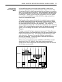
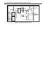
HD65 & HD130 Stepper
Drives User Guide
For engineering
assistance in Europe:
Parker Hannifin plc
Digiplan Division
21 Balena Close
Poole, Dorset
England, BH17 7DX
Telephone: 0202-699000
Fax: 0202-695750
Part No: 1600.051.07
7th September 1992
For engineering
assistance in the U.S.:
Parker Hannifin Corporation
Digiplan Division
5500 Business Park Drive
Rohnert Park, CA 94928
USA
Telephone: (800) 358-9070
Fax: (707) 584-8015
IMPORTANT INFORMATION FOR USERS
Installation and Operation of Digiplan Equipment
It is important that Digiplan motion control equipment is installed and operated in such a way that all applicable
safety requirements are met. It is your responsibility as a user to ensure that you identify the relevant safety
standards and comply with them; failure to do so may result in damage to equipment and personal injury. In
particular, you should study the contents of this user guide carefully before installing or operating the
equipment.
Under no circumstances will the suppliers of the equipment be liable for any incidental, consequential or special
damages of any kind whatsoever, including but not limited to lost profits arising from or in any way connected
with the use of the equipment or this user guide.
!
SAFETY WARNING
High-performance motion control equipment is capable of producing rapid movement and very high forces.
Unexpected motion may occur especially during the development of controller programs. KEEP WELL CLEAR
of any machinery driven by stepper or servo motors. Never touch it while it is in operation.
High voltages exist within enclosed units, on rack system backplanes (motherboards) and on transformer
terminals. Keep clear of these areas when power is applied to the equipment.
The information in this user guide, including any apparatus, methods, techniques, and concepts described
herein, are the proprietary property of Parker Digiplan or its licensors, and may not be copied, disclosed, or
used for any purpose not expressly authorised by the owner thereof.
Since Digiplan constantly strives to improve all of its products, we reserve the right to modify equipment and
user guides without prior notice. No part of this user guide may be reproduced in any form without the prior
consent of Digiplan.
© Digiplan Division of Parker Hannifin plc, 1991
– All Rights Reserved –
User Guide Change Summary
The following is a summary of the primary changes to this user guide
since the last version was released. This user guide, version
1600.051.07, supersedes version 1600.051.06.
This user guide has been updated to incorporate the style common
to our user guides. Some drawings have also been updated. All
technical information remains unchanged.
CONTENTS
Table of Contents
Introduction.............................................................................................................. 1
Product Description......................................................................................... 1
Specification....................................................................................................1
Power Connections......................................................................................... 2
Motor Connections ..........................................................................................2
General Wiring & Earthing Recommendations ............................................... 2
Transformer Primary Connections ..................................................................5
Control Signals................................................................................................8
Setting Up the Drive ........................................................................................10
Motherboard Link .................................................................................10
Current Programming...........................................................................11
Stepping Mode Selection .....................................................................11
Standby Current ................................................................................... 12
Boost Current .......................................................................................12
Anti-resonance Dropout Speed ............................................................12
Current Profile Setting (Half-step Mode) ..............................................13
Fuses .............................................................................................................. 14
Test Points ......................................................................................................14
MS20 Microstep Card ..............................................................................................15
Description ......................................................................................................15
Setting Up the Microstep Card ........................................................................16
Operation of the Drive Protection Systems........................................................... 17
Overload Protection ........................................................................................17
Supply Failure Protection................................................................................ 17
Overtemperature Protection............................................................................17
Fault-finding Guide.................................................................................................. 19
Returning the System...................................................................................... 20
i
HD65 & HD130 STEPPER DRIVES USER GUIDE
1
Introduction
Product
Description
The HD65 and HD130 stepper drives are bipolar, chopper-regulated
units designed to operate with a wide range of motors. They
incorporate all power supply components for direct operation from a
mains transformer. The two drives deliver nominal motor currents of
6.5A and 13A respectively, and both operate at a motor supply of
240V DC.
All translation and current control functions are performed by a ULAhybrid translator, and this incorporates a number of useful features
including an anti-resonance circuit and automatic current square-off.
The drives can be fitted with the optional MS20 microstep card which
gives 1000 or 2000 steps/rev from a standard 200-step motor.
Specification
Nominal output current (2 phase on)
Motor supply voltage
Current boost
Maximum boost duration
Nominal standby reduction
Current programming
Current programming steps
Maximum stepping rates
6.5A (HD65), 13A (HD130)
240v DC
30%
5 seconds (internally limited)
50% (at rated current)
By DIL switch down to 50% of rated current
0.5A (HD65), 1A (HD130)
Full step 20kHz
Half step 50kHz
1/5 step 100kHz
1/10 step 100kHz
AC power requirements
Motor supply range 86-172v AC at 7A
(HD65), 14A (HD130).
Logic supply 18-0-18 at 850mA.
Fan supply (HD130) 115v RMS at 150mA.
Auxiliary DC output
+24v at 250mA (500mA with external
2200uF capacitor added)
Input logic levels
Logic 1 level +11v to +13v or open circuit.
Logic 0 level <+1v or short circuit to 0v
Input impedance
Clock input 1K to +12v
Other inputs 4K7 to +12v
Logic outputs
Open-collector NPN, +30v max. (off),
15mA max. (on)
Operating temperature range
0° - 50°C
Maximum heatsink temperature
85°C
Suitable motor type
2/4 phase; 4, 6 or 8-lead (5-lead not
suitable)
Typical motor current rating (bipolar) 6A - 9A (HD65)
12A - 18A (HD130)
Minimum motor inductance
1.5mH (HD65)
0.75mH (HD130)
Weights
3.2kg (HD65)
4kg (HD130)
Dimensions (mm
Height overall 262, pcb only 233, Depth
overall 262, pcb only 220 Width 106 (4.2"
nominal)
2
HD65 & HD130 STEPPER DRIVES USER GUIDE
Power
Connections
Power and motor connections are made to the drive motherboard as
illustrated in Figure 1. Screw terminals are provided on the
motherboard for the AC input from the mains transformer. Suitable
transformers for the HD drives are type TO132 for a single HD65
and type TO124 for two HD65 drives or a single HD130. Refer to
page 5 for the primary connections for various AC supply voltages.
Connect the 172-volt winding to terminals L1 and L2 on TB1.
Connect one 172-volt secondary to each drive when using a TO124
to power two HD65 drives, and connect the two 172-volt windings in
parallel when operating an HD130 (see diagrams on page 4). If a
three-phase transformer is used, the line-to-line voltage must be 172
volts and connections are made to terminals L1, L2 and L3.
The HD130 requires 115 volts AC to operate its cooling fan and
these connections are made to the "FAN" terminals on TB1. If
required this supply can come directly from 115v AC mains. The fan
connections are commoned together on a multi-axis rack.
The logic supply requires 18-0-18v AC and this supply is connected
to terminals 9, 10 and 11 respectively on socket SK1. The logic
supply connections are also commoned together on a multi-axis
rack.
Motor
Connections
General
Wiring &
Earthing
Recommenda
-tions
Motor connections are made to screw terminals on TB2. Refer to
pages 6 and 7 for motor connection details, and ensure that the
connections are made correctly. 1.5mm2 cable is recommended.
To reverse the direction of rotation relative to the direction control
input, interchange the connections to 1A and 1B.
It is advisable to use a central earth stud mounted on the rack end
plate or close to it. Mains earth, the transformer screen, the rack 0v
bus and the enclosure metalwork should all be connected to this
stud. In particular, the connection to the rack 0v bus should use
1mm2 cable and should be kept as short as possible.
Input/output signal connections longer than about 500mm should
use wires having a collective or individual screen. In general it is
better to route signal connections separately from power and motor
connections. If the motor leads run in the same trunking as signal
leads, then either the motor or signal leads should be screened.
Connect the screen to the earth stud at one end, and insulate it at
the remote end.
HD65 & HD130 STEPPER DRIVES USER GUIDE
3
Where signal connections pass between units mounted in different
enclosures and separately energised from the mains, optical
isolation of all communication lines is recommended. It is still
desirable that all such isolated systems have their 0v rails directly
connected to earth.
Motor leads should be collectively screened if they run close to
power switching lines, particularly those driving unsuppressed
inductive loads. Whilst noise picked up on the motor leads is
unlikely to affect the motor directly, the noise gets coupled back into
the drive system and can cause problems as a result.
Contactors and relays feeding inductive loads should be adequately
suppressed.
4
HD65 & HD130 STEPPER DRIVES USER GUIDE
TB2
115V
TB2
2A
2B
1B
1A
TB1
0V
115V
0V
FAN
FAN
0V
172V
172V
Motor
C1
L1
L2
2A
2B
1B
1A
TB1
Motor
C1
C2
C2
0V
172V
HD65
HD130
0V
~
~
18V
0V
1 SK1 9
1 SK1 9
18V
0V
SK2
18V
SK2
18V
8
8
16
T0132
Transformer
16
T0124
Transformer
Connections for Single HD65 Drive
Connections for Single HD130 Drive
TB2
115V
TB2
2A
2B
1B
1A
TB1
0V
172V
0V
Motor
C1
L1
L2
2A
2B
1B
1A
TB1
C2
HD65
C2
HD65
172V
~
0V
18V Bus
Connections
18V
0V
1 SK1 9
1 SK1 9
SK2
SK2
18V
8
16
8
Motor
C1
L1
L2
16
T0124
Transformer
Connections for Two HD65 Drives
Figure 1. Power and Motor Connections
HD65 & HD130 STEPPER DRIVES USER GUIDE
Transformer
Primary
Connections
Standard Digiplan mains transformers for HD series drives have a
four-winding primary arrangement as shown below. The table
shows the primary voltages which can be selected, the sample
connections being for 240v AC. Always wire the transformer primary
first, then check the secondary output voltages on open-circuit
BEFORE connecting to the drive.
2
1
3
120
5
120
6
20
0
20
8
110
12
20
20
16
15
0
120
110
11
14
13
120
110
10
9
4
7
110
0
0
Figure 2. Transformer Primary Windings
Input Voltage
100
110
120
200
220
230
240
360
380
400
420
440
460
480
5
AC Line 1
1
5
1
1
5
1
1
5
5
1
1
5
5
1
AC Line 2
9
13
13
10
14
14
14
12
16
12
16
16
16
16
Links
1, 2, 3 & 4; 9, 10, 11 & 12
5, 6, 7 & 8; 13, 14,15 & 16
1, 2, 3 & 4; 13, 14,15 & 16
9 & 2; 11 & 4; 1 & 3;10 & 12
13 & 6; 15 & 8; 5 & 7; 14 & 16
1 & 3; 13 & 6; 15 & 8; 14 & 16
1 & 3; 13 & 2; 15 & 4; 14 & 16
9 & 6; 10 & 7; 11 & 8
9 & 6; 10 & 7; 11 & 8
9 & 2; 10 & 3; 11 & 4
9 & 2; 10 & 3; 11 & 4
13 & 6; 14 & 7; 15 & 8
13 & 6; 14 & 3; 15 & 4
13 & 2; 14 & 3; 15 & 4
6
HD65 & HD130 STEPPER DRIVES USER GUIDE
MOTOR CONNECTION DATA - WINDINGS IN SERIES
N.C. - no connection.
MAKE
TYPE
1A
1B
2A
2B
NOTES
Evershed &
Vignoles
6-lead
Red
Green
Blue
Yellow
Brown & Black N.C.
8-lead
Red
Green
Blue
Yellow
Link Grey & Pink, link
White & Violet
T.box
6-lead
1
Black
3
Orange
4
Red
2
Yellow
Link 5 & 6, link 7 & 8
White/Blk/Org,
White/Red/Yel N.C.
8-lead
Black
Orange
Red
Yellow
Link Wh/Blk & Wh/Org
Link Wh/Red & Wh/Yel
T.box
6-lead
1
Red
3
Red/Wh
2
Grn
4
Grn/Wh
Link 5 & 6,link 7 & 8
White & Black N.C.
T.box (x6)
8-lead
1
Red
3
Red/Wh
4
Grn
5
Grn/Wh
2 & 6 N.C.
Link Black & White, link
Org & Blk/Wh
Stebon
T.box (x8)
8-lead
1
Red
3
Yel
5
Pink
4
Blk
Link 2 & 6, link 7 & 8
Link Blue & violet, link
White & Grey
G.E.C.
M.A.E.
T.box
T.box
6-lead
1
1
Grn/Wh
2
2
Grn
3
3
Red
4
4
Red/Wh
Link 5 & 6, link 7 & 8
Link 5 & 6, link 7 & 8
White & Black N.C.
8-lead
Black
Orange
Red
Yellow
Link Wh/Blk & Wh/Org,
Link Wh/Red & Wh/Yel
Zebotronics
Oriental
Sonceboz
T.box
T.box
6-lead
8-lead
6
1
Black
Green
5
4
Green
Grn/Wh
8
5
Red
Red
7
8
Blue
Red/Wh
Japan Servo
Escap
6-lead
8-lead
Red
Brown
Blue
Org/Wh
Green
Red
Yellow
Yel/Wh
Bodine
8-lead
Brown
Orange
Yellow
Red
Link 1 & 3, link 2 & 4
Link 2 & 3, link 6 & 7
Yellow & White N.C.
Link Org & Blk/Wh, link
Black & White
2 x White N.C.
Link Brn/Wh & Org,
Link Red/Wh & Yellow.
Link Wh/Brn & Wh/Org,
link Wh/Yel & Wh/Red.
Sigma
Astrosyn,
Rapidsyn,
Slo-syn
Slo-syn
T.box
Digiplan/Compumotor
RM Motor
8-lead
1
3
4
2
Link 5 & 7,link 6 & 8
Black
Orange
Red
Yellow
LinkWh/Blk & Wh/Org.
Link Wh/Red & Wh/Yel
Digiplan/Compumotor
QM Motor
8-lead
Red
Black
White
Green
Link Yel & Blue
Link Org & Brown
HD65 & HD130 STEPPER DRIVES USER GUIDE
7
MOTOR CONNECTION DATA - WINDINGS IN PARALLEL
For 6-lead motors, connections shown are for one half-winding.
N.C. - no connection.
MAKE
TYPE
1A
1B
2A
2B
NOTES
Evershed &
Vignoles
6-lead
Red
Brown
Blue
Black
Grn & Yellow N.C.
8-lead
Rd &
Pink
Grn &
Grey
Blue &
Violet
Yel &
White
T.box
6-lead
1&6
Black
3&5
Wh/Blk/
Orange
4&8
Red
2&7
Wh/Red/
Yellow
8-lead
Black &
Wh/Or
Or &
Wh/Blk
Red/
Wh/Yel
Yel &
Wh/Red
T.box
6-lead
1&5
Red
3&6
Black
2&7
Green
4&8
White
Slo-syn
T.box(x6)
8-lead
1
Red &
White
6
Blk &
Red/Wh
4
Grn &
Blk/Wh
2
Org &
Grn/Wh
Stebon
T.box(x8)
8-lead
1&2
Rd &
Blue
3&6
Yel &
Violet
4&7
Wh &
Pink
5&8
Black &
Grey
G.E.C.
M.A.E.
T.box
T.box
6-lead
1&6
1&6
Grn/Wh
2&5
2&5
White
3&8
3&8
Red
4&7
4&7
Black
8-lead
Black &
Wh/Or
Or &
Wh/Blk
Red &
Wh/Yel
Yel &
Wh/Red
Zebotronics
Oriental
Sonceboz
T.box
T.box
6-lead
8-lead
Japan Servo
Escap
6-lead
8-lead
Bodine
8-lead
3&6
1&2
Black
Grn &
Blk/Wh
Red
Brn &
Orange
Brn &
Wh/Or
1&5
3&4
Yellow
Or &
Grn/Wh
White*
Brn/Wh &
Org/Wh
Wh/Brn &
Orange
4&8
5&6
Red
Red &
White
Green
Red &
Yellow
Yel &
Wh/Red
2&7
7&8
White
Blk &
Red/Wh
White*
Red/Wh &
Yel/Wh
Wh/Yel &
Red
1&7
3&5
4&6
2&8
Black &
Wh/Or
Orange &
Wh/Black
Red &
Wh/Yellow
Yellow &
Wh/Red
Blk & Yellow
Wh & Brn
Green & Org.
Sigma
Astrosyn,
Rapidsyn,
Slo-syn
T.box
Digiplan/Compumotor
RM Motor
8-lead
Digiplan/Compumotor
QM Motor
8-lead
Red & Blue
* Use correct White for each phase.
Or & Yellow N.C.
Red/Wh &
Grn/Wh N.C.
3 & 5 N.C.
Grn & Red N.C
Grn & Blue N.C.
HD65 & HD130 STEPPER DRIVES USER GUIDE
1
SK1
24V
FAULT
ZERO
PHASE
BOOST
9
18V
0V
SK2
18V
0V
ANTI
RES
SQ OFF
EXT RESET
DIRN
CK
ENG
SYNC
0V
8
SYNC
16
R1
R2
R29
R3
R4
R5
R6
8
TP1 TP2
D1
D2
TP3 TP4
SYNC
Figure 3. Terminals on HD-Series Motherboard
Control
Signals
When the rack system is equipped with Digiplan control modules,
the signal connections are made via 8-way jumper cables fitted to a
mating connector on each drive motherboard. In these systems it is
not normally necessary to make external signal connections to the
drives, since all control signals go to the control card motherboard.
Where the rack is equipped with drives only, control connections are
made to the two-part connectors on the drive motherboard (see
Figure 3). The following list describes the function of each terminal.
PIN 1 - +24v. This is an auxiliary fused output which provides 24
volts unregulated at up to 500mA. If the load is to exceed 250mA, fit
an external 2200uF 35v capacitor between this terminal and terminal
8 (0v). Remember to observe the correct polarity.
PIN 2 - Fault. This is a composite output signal which goes high in
the event of an overload, short circuit, supply failure or
overtemperature fault. It is driven by an open-collector transistor
and should therefore be pulled up by an external resistor when the
signal is required. The resistor should be returned to a voltage no
higher then 30 volts and should not allow more than 15mA to flow
when the output is low.
HD65 & HD130 STEPPER DRIVES USER GUIDE
9
__________
PIN 3 - Zero Phase. The zero phase output is low when the
translator is in its primary state. This occurs every 8 steps in the
half-step mode, and the signal will therefore go low 50 times per rev.
with a 200 step/rev. motor. It corresponds with current flowing from
A to B in each motor phase. At switch-on the translator is always
reset to the zero phase state. The signal is used when establishing
a mechanical reference or "datum" position. Ratings are the same
as for the fault circuit. An LED on the front of the drive shows when
the translator is in the zero phase state.
_____
PIN 4 - Boost. Connecting this input to 0v increases the motor
current by approximately 30%. The drive is not rated for continuous
operation with boost applied, and if the input is held low the current
will revert to its normal level after 5 seconds.
PIN 5 - Direction. Taking this input low will reverse the direction of
motor rotation. The direction should only be changed when the
motor is stationary or running within the start/stop speed range. Do
not change the direction signal within 5uS of the low-going edge of a
clock pulse.
_____
PIN 6 - Clock. A low-going transition on this input causes the motor
to advance one step. The width of the low-going pulse should be at
least 4uS. Ensure that the pulse width is consistent with the
maximum input frequency, which can be as high as 100kHz with the
microstepping option operating at 2000 steps/rev.
________
PIN 7 - Energise. This input enables the motor to be de-energised
so that it may be rotated slowly by hand without switching the
system off. Switch 9 on the motherboard must be turned off in order
to use this facility. The input should then be connected to 0v in order
to energise the motor. DO NOT turn the motor at high speed with
the drive de-energised as this may overload the power dump circuit.
Similarly the drive should not be de-energised whilst the motor is
running.
PIN 8 - 0v. Use this terminal as a common return for the control
signals.
PIN 9 - 18v AC in. See power connection on page 4.
PIN 10 - 0v. Connection for the 18v AC centre tap.
PIN 11 - 18v AC in.
PIN 12 - 0v. An additional common return for control inputs.
PIN 13 - Anti-resonance. With this input connected to 0v, the drive
operates in its normal chopping mode at all speeds. With the input
high or open-circuit, the anti-resonance system is brought into
10 HD65 & HD130 STEPPER DRIVES USER GUIDE
operation provided the speed is less than about 440 half steps/sec.
This speed is programmable (see "Setting up the drive"). Switch 6
may be turned on to hold this input permanently at 0v and so prevent
the anti-resonance system from operating.
_________
PIN 14 - Square-off. When this input is open-circuit, the motor
current is "squared off" to the one-phase-on level at approximately
3200 half steps/sec. This gives improved midrange torque
compared with the usual two-level current profile. However the input
may be taken to 0v which will cause the drive to square off
permanently. Square-off can also be disabled (see programming
switch 0 under "Setting Up the Drive").
_____________
PIN 15 - External Reset. Connect to 0v to reset a fault condition
(provided the cause of the fault has been removed). An alternative
method of resetting is to temporarily remove power.
PIN 16. Sync. Connecting the sync terminals of several drives
together will cause all the chopper regulators to synchronise,
eliminating beat fre-quencies and minimising the audible noise at
standstill. Turret lugs are provided on each side of the motherboard
to simplify interconnection between adjacent drives. All drives in a
single rack may be interconnected in this way, but it is not
recommended to connect drives in different racks together.
Setting Up the
Drive
Motherboard Link
The two-position link on the motherboard is fitted in position "a" for a
standard drive operating in the full or half step mode. Position "b" is
used when the optional microstep card is fitted.
A 10-position programming switch on the motherboard sets up the
main operating conditions, and in most applications this will be the
only adjustment required. Certain parameters are determined by
resistors on the drive and on the motherboard, and again the values
as supplied have been optimised for all normal applications.
Information is given on changing these parameters should this prove
necessary.
The functions of the programming switch are as follows:
1-4:
Current programming. (see next section).
5:
Square-off switch. Turning this switch "on" has the same
effect as grounding the "square-off" terminal, i.e. gives
permanent square-off at the one-phase-on current except at
standby.
HD65 & HD130 STEPPER DRIVES USER GUIDE 11
Current
Programming
6:
Anti-resonance. Turn "on" to inhibit the anti-resonance
circuit (closing this switch performs the same function as
connecting terminal 13 to 0v.).
7 & 8:
Mode switches. (See table on following page under Stepper
Mode Selection.)
9:
Energise. Turn "on" to keep the drive permanently
energised (closing this switch performs the same function as
connecting terminal 7 to 0v).
0:
Square-off inhibit. Turn "on" to delay the onset of square-off
until a clock pulse frequency of 15kHz is reached. This
effectively inhibits the square-off function. Square-off
operates normally with this switch "off". The switch is only
active in the 200 or 400 step/rev mode.
The following table shows the settings of switches 1-4 for various
motor currents. The values shown in the table are two-phase-on
levels, and are nominal values only since they depend to some
extent on motor inductance. The selected current should not exceed
the current rating of the motor. In the half step mode the one-phaseon current is approximately 35% greater than the level with two
phases on, giving a similar electrical power into the motor. Bear in
mind that if permanent square-off is selected there will be a
significant increase in average motor current at low speeds.
DIP Switch Settings
1
2
3
4
OFF OFF OFF OFF
ON OFF OFF OFF
ON ON
OFF OFF
OFF OFF ON
OFF
OFF ON
ON
OFF
OFF OFF OFF ON
ON ON
OFF ON
ON ON
ON
ON
Stepping Mode
Selection
Motor Current
for HD65
6.5A
6A
5.5A
5A
4.5A
4A
3.5A
3A
Motor Current
for HD130
13A
12A
11A
10A
9A
8A
7A
6A
The following table shows the stepping modes selected by switches
7 and 8.
12 HD65 & HD130 STEPPER DRIVES USER GUIDE
Resolution
(with 200 step/rev
motor)
200 steps/revolution
400 steps/revolution*
1,000 steps/revolution
2,000 steps/revolution**
Stepping
Mode
Full step
Half step
1/5 step
1/10 step
DIP Switch
Settings
7
8
ON
OFF
OFF OFF
OFF ON
ON
ON
* Default resolution setting for HD65/130
** Default resolution setting for HD65/130M
The 1/5 and 1/10 step modes only apply if the optional microstep
card is fitted (types HD65M and HD130M). In a standard drive
(HD65 or HD130) the half-step mode is almost always preferable to
full step, since the slight loss of torque is more than offset by
smoother performance at low speeds.
Standby Current
The motor current is automatically reduced at standby; the reduction
depends on the current setting, and is 50% with the drive set to its
full current. At minimum current setting the standby reduction is to
approximately 80% of regulated current.
A larger reduction may be obtained by changing R76 on the drive,
which is normally set at 560 ohms. Reduce the value to reduce the
standby current further. This resistor is located at the bottom of the
PCB opposite the main power supply capacitor, and is accessible
without dismantling the drive. Do not use a value higher than 560R
without consulting Digiplan.
The standby current may be measured by a meter connected in
series with one of the motor leads, or by using an oscilloscope (see
"Test points" on page 14). Note that in modes other than full-step
the current will vary with step position, so it is safest to make the
measurement with the drive on zero phase. Remember to switch off
before disconnecting a motor lead.
Boost Current
Anti-resonance
Dropout Speed
When boost is applied the motor current increases by approximately
30%. This is set by R77 on the drive and is normally 68K. The
resistor is located next to R76 opposite the power supply capacitor,
and its value may be increased in order to reduce the amount of
boost. Do not use a value lower than 68K.
The anti-resonance circuit is inhibited at speeds above 440 full
steps/sec, and this is determined by R1 on the motherboard. The
standard value is 47K, and halving the resistor value will double the
dropout frequency.
HD65 & HD130 STEPPER DRIVES USER GUIDE 13
Current Profile
Setting (Half-step
Mode)
In the half step mode, a two-level current profile is used at low
speeds to equalise torque on alternate steps. Figure 4 shows this
current profile with A and B representing the two-phase-on condition,
and C the one-phase-on condition. When two phases are energised
the current levels are 6.5A and 13A for the HD65 and HD130 drives
respectively. These current levels are increased in the one-phaseon condition to 9A (HD65) and 18A (HD130) to help maintain the
torque on intermediate steps.
The function of the square-off circuit is to maintain torque output in
the middle speed range where the average motor current is falling
off due to winding inductance. The current profile is "squared off" to
the one-phase-on level at 3200 half steps/sec. The square-off
speed is determi-ned by R2 on the drive motherboard. The standard
value is 33K, and halving the resistor value will double the square off
speed. Do not change this resistor value without first consulting
Digiplan.
Turning on switch 5 will give permanent square-off. This will give a
significant increase in low speed torque, but will also increase motor
noise and temperature rise. This setting should therefore be used
with discretion. Square-off is logically inhibited at standstill to
prevent overheating. Turning on switch 0 will have the effect of
permanently inhibiting square-off.
When using a microstepping drive (HD65M or HD130M), switch 5
should be in the "off" position. Note that selecting permanent
square-off in a micro-step mode would effectively return the drive to
the full step current profile.
Step Pulses
1
2
3
4
5
6
7
8
9
C
A
B
Phase 1
Phase 2
Figure 4. Normal Current Profile (Half-step Mode)
14 HD65 & HD130 STEPPER DRIVES USER GUIDE
Step Pulses
1
2
3
4
5
6
7
8
9
Phase 1
Phase 2
Figure 5. Current Profile with Square-off
Fuses
The main fuses are fitted on the inside of the motherboard and are
accessible by removing the drive. Ensure that the power has been
turned off before any fuses are inspected. Fuse ratings are as
follows:
FS1
- Fan fuse, 500mA quick acting.
FS2
- Power dump fuse, 2 amp time-delay.
FS3, FS4, FS5 - 172v AC input fuses;
12.5 amp time-delay for HD65,
25 amp time-delay for HD130.
FS6, FS7
- 18v AC input fuses, 1 amp time-delay.
FS8
- 24v DC auxiliary output fuse, 500mA quick acting.
In addition there is an internal fuse within the drive module itself, in
the 240v DC supply between the main capacitor and the switch set.
This is a quick-acting type rated at 10A (HD65), 20A (HD130).
All fuses are 1-1/4 inch type. HBC (high breaking capacity) fuses
are recommended for fuses FS3, FS4, FS5 and the internal drive
fuse.
Test Points
At the base of the motherboard are test points which may be used to
monitor motor current using an oscilloscope. The sensitivity is 10.8
amps/volt for the HD65 and 21.5 amps/volt for the HD130.
TP1
TP2
TP3
TP4
-
phase 1 current monitor
phase 2 current monitor
reference voltage (factory use only)
0v (use for scope probe earth lead)
HD65 & HD130 STEPPER DRIVES USER GUIDE 15
MS20 Microstep Card
Description
The HD65M and HD130M drives are fitted with the MS20 Microstep
Card which gives improved resolution and smoothness from a
standard motor. Microstepping is achieved by proportioning the
currents in the two motor windings so that the rotor takes up a series
of intermediate step positions. In this way a standard 200-step
motor may be made to perform 1000 steps/rev (1/5 step mode), or
2000 steps/rev (1/10 step mode).
Ideally the intermediate current levels will produce equally-spaced
step positions as well as equal dynamic torque, without exceeding
the dissi-pation limit of the motor. In practice this can be difficult to
achieve and a compromise has to be made. If the current levels are
plotted against rotor position the resulting profile resembles a
sinusoidal shape. The optimum profile varies from one type of motor
to another, and for this reason the MS20 card has a selection of 64
alternative profiles which are stored in an Eprom and selected by an
8-position DIL switch. This switch is accessible between the two
edge connectors at the rear of the drive. The card has been
programmed with a set of profiles which have been derived
theoretically.
A sinusoidally-based profile is obtained with all bit switches in the
"off" position. Switches 2 - 6 may be used to set in an increasing
binary number which will cause the profile to progressively "fill out"
from a sinewave (switch 2 is the least significant bit). By turning on
switch 7, increasing the number in switches 2 - 6 will then trim the
profile down towards a triangular shape. In practice this tends to be
more useful than the "filled out" form. Switches 1 and 8 should be
left permanently off.
A few examples are shown below - a "1" indicates that the switch is
"on" .
8
0
0
0
0
0
0
0
Setting Up the
Microstep
Card
7
0
0
0
0
1
1
1
Switch position
6
5
4
3
0
0
0
0
0
0
0
0
1
0
0
0
1
1
1
1
0
0
0
0
1
0
0
0
1
1
1
1
Profile
2
0
1
0
1
1
0
1
1
0
0
0
0
0
0
0
Sinewave
Slight fill-out
Moderate fill-out
Maximum fill-out
Slight trimming
Moderate trimming
Maximum trimming
Link 1 on the microstep card should be left in position "a". This link
is provided for future implementation of an alternative profile in
boost.
16 HD65 & HD130 STEPPER DRIVES USER GUIDE
Link 2 is normally in position "a". Moving it to position "b" will cause
a sinusoidal profile to be selected at standstill. With some motors
this will give better static positioning than a filled-out or trimmed
profile. Choosing the optimum profile for a given motor is best
carried out with equipment which will accurately measure shaft
position and torque. Since this is seldom available, empirical
methods are normally used and can give perfectly acceptable
results.
The logical starting point is with all switches off to give a sinusoidal
profile. Attach a light pointer to the motor shaft (cable ties are ideal),
and run the motor very slowly. It will be visually apparent whether
the steps are all similar or there is a cyclic variation in step size as
the shaft rotates. Slowly increase the speed, and the sound from the
motor will give an idea of the relative torque produced on successive
steps. Again a cyclic pulsing sound implies associated torque
variations
Switch off, remove the drive and try setting a trimmed profile (see
table on page 15). Repeat the exercise and compare the results.
From this it should be clear whether more or less trimming is
required, so choose another setting and try again. It is usually best
to aim for the smoothest rotation rather than best static positioning.
If the application demands significant torque from the motor, repeat
the exercise with the motor loaded. This method usually reveals the
useful range of profiles quite quickly.
SINEWAVE
FILLED-OUT
TRIMMED
Figure 6. Microstepping Current Profiles
HD65 & HD130 STEPPER DRIVES USER GUIDE 17
Operation of the Drive Protection Systems
There are three basic protection systems built into the drive, and
these guard against damage caused by overloads, power supply
faults and excess temperature. Operation of any of these protection
circuits will de-energise the drive, and the reason for shutdown is
indicated by an LED on the front of the drive. Provided the cause of
the fault has been removed the drive may be re-energised by taking
control terminal 7 to 0v or by temporarily removing power. Figure 7
is a simplified diagram of the protection circuitry.
Overload
Protection
An overload condition may be brought about by incorrect motor
connection, short circuits across the motor terminals or any other
condition causing excess current to flow. It may also arise if a very
low inductance motor is desynchronised during deceleration. In any
of these circumstances the overcurrent comparator will set the fault
latch, turning on the appropriate LED and giving a fault output signal.
Supply
Failure
Protection
Overtemperature
Protection
Should the high-voltage supply rise excessively, or any of the logic
supply rails fall outside preset limits, the supply protection circuit
comes into operation. It functions by using a comparator to compare
each of the supply rails with fixed reference levels. If the preset
limits are exceeded, the fault latch is set and the supply failure LED
is illuminated. Note that an excessive rise in the high-voltage supply
may result from failure of the power dump fuse FS2.
This mode of shutdown occurs if the heatsink temperature reaches
85°C, which will generally be the result of inadequate cooling. The
heatsink temperature is monitored by a thermal sensor mounted on
the drive pcb. The output from the sensor sets the fault latch
directly, and illuminates the Overtemperature LED. It will be
necessary to allow time for the drive to cool down before it can be
reset.
18 HD65 & HD130 STEPPER DRIVES USER GUIDE
PROTECTION CIRCUIT
Overtemp
Thermal
Sensor
Phase 1
Current
Phase 2
Current
-H.T.
-5V
+5V
+12V
+24V
Overload
Comp.
Fault
Latch
Fault
Output
Overload
Supply
Fault
0V
Zero
Phase
Overvolts
Comp.
Figure 7. Simplified Protection Circuit
Zero Phase
Output
HD65 & HD130 STEPPER DRIVES USER GUIDE 19
Fault-finding Guide
If there is no response from the motor and the more obvious checks
have been made, the following guide may help to identify the
problem. Before going through the procedure, make sure that the
motor shaft is free to rotate with the drive switched off.
Turn the drive on and see which LEDs are illuminated. Then go to
the appropriate heading below.
Zero phase -
listen for audible noise from the motor. If there
is none, check for open-circuit motor leads,
check energise input (motherboard switch 9 on
or terminal 7 connected to 0v).
Overload -
switch off, disconnect the motor and switch on
again. If the overload LED is still on, the drive
has been damaged. If not check for short
circuits or crossed motor connections. A very
low inductance motor could also cause the
drive to trip out, if this is suspected try
connecting the motor in series.
Supply failure -
check the AC supplies coming into the
motherboard. If these are OK, switch off, wait
for 3 minutes, unplug the drive and check the
fuses on the back of the motherboard. If OK,
there is probably an internal failure within the
drive.
Over-temperature - the drive has overheated and should be
switched off and left to cool. If it was previously
working satisfactorily, better cooling is needed.
On the HD130, check that the fan is running
and is not obstructed.
None at all -
check as for "supply failure".
If there is audible noise from the motor but the drive does not
respond to clock pulses, look to see if the zero phase LED flashes.
If clock pulses are entering the drive, the LED should flash or go dim
depending on speed. If it doesn't, the drive is either not getting any
pulses or is not responding to them. Make sure the clock pulses go
low for at least 4uS and that the logic low level is below +1v.
CAUTION
Note that if the dump fuse (FS2) is blown it will take approximately 3 minutes for the main supply capacitor to discharge.
Always allow adequate time for the capacitor to discharge
20 HD65 & HD130 STEPPER DRIVES USER GUIDE
before unplugging the drive. Whilst the drive will operate with
FS2 missing or blown, it is essential that this fuse is fitted for
safety reasons.
Returning the
System
If you must return your HD Drive to effect repairs or upgrades, use
the following steps:
1. Get the serial number and the model number of the defective
unit, and a purchase order number to cover repair costs in the
event the unit is determined by the manufacturers to be out of
warranty.
2. Before you return the unit, have someone from your organisation
with a technical understanding of the equipment and its
application include answers to as many of the following questions
as possible:
•
What is the extent of the failure/reason for return?
•
How long did it operate?
•
Did any other items fail at the same time?
•
What was happening when the unit failed (i.e., installing the unit,
cycling power, starting other equipment, etc.)?
•
How was the product configured (in detail)?
•
What, if any, cables were modified and how?
•
With what equipment is the unit interfaced?
•
What was the application?
•
What was the system environment (temperature, enclosure,
spacing, unit orientation, contaminants, etc.)?
•
What upgrades, if any, are required (hardware, software, user
guide)?
3. In the UK, call Digiplan for a GRA (Goods Returned
Authorisation) number. Returned products cannot be accepted
without a GRA number. The phone number for Digiplan Repair
Department is 0202 690911. For Customer Service/Applications
Department phone 0202 699000.
HD65 & HD130 STEPPER DRIVES USER GUIDE 21
Ship the unit to:
Parker Hannifin plc
Digiplan Division,
21, Balena Close,
Poole,
Dorset,
England.
BH17 7DX
4. In the USA, call Parker Compumotor for a Return Material
Authorisation (RMA) number. Returned products cannot be
accepted without an RMA number. The phone number for
Parker Compumotor Applications Department is (800) 358-9070.
Ship the unit to:
Parker Hannifin Corporation
Digiplan Division
5500 Business Park Drive
Rohnert Park, CA 94928
Attn: RMA # xxxxxxx
5. Elsewhere: Contact the distributor who supplied the equipment.