1
Installation Guide
Color CCTV Camera
Model No.
WV-CW590/G
WV-CW594E
Before attempting to connect or operate this product,
please read these instructions carefully and save this manual for future use.
The model number is abbreviated in some descriptions in this manual.
We declare under our sole responsibility that the product to which
this declaration relates is in conformity with the standards or other
normative documents following the provisions of Directives
2006/95/EC and 2004/108/EC.
Wij verklaren als enige aansprakelijke, dat het product waarop
deze verklaring betrekking heeft, voldoet aan de volgende
normen of andere normatieve documenten, overeenkomstig de
bepalingen van Richtlijnen 2006/95/EC en 2004/108/EC.
Wir erklären in alleiniger Verantwortung, daß das Produkt, auf das
sich diese Erklärung bezieht, mit den folgenden Normen oder
nor mativen Dokumenten übereinstimmt. Gemäß den
Bestimmungen der Richtlinie 2006/95/EC und 2004/108/EC.
Vi erklærer os eneansvarlige for, at dette produkt, som denne
deklaration omhandler, er i overensstemmelse med standarder
eller andre normative dokumenter i følge bestemmelserne i
direktivene 2006/95/EC og 2004/108/EC.
Nous déclarons sous notre propre responsabilité que le produit
auquel se réfère la présente déclaration est conforme aux normes
spécifiées ou à tout autre document normatif conformément aux
dispositions des directives 2006/95/CE et 2004/108/CE.
Vi deklarerar härmed vårt fulla ansvar för att den produkt till vilken
denna deklaration hänvisar är i överensstämmelse med de
standarder eller andra normativa dokument som framställs i
direktiv nr 2006/95/EC och 2004/108/EC.
Nosotros declaramos bajo nuestra única responsabilidad que el
producto a que hace referencia esta declaración está conforme
con las normas u otros documentos normativos siguiendo las
estipulaciones de las directivas 2006/95/CE y 2004/108/CE.
Ilmoitamme yksinomaisella vastuullamme, että tuote, jota tämä
ilmoitus koskee, noudattaa seuraavia standardeja tai muita
ohjeellisia asiakirjoja, jotka noudattavat direktiivien 2006/95/EC ja
2004/108/EC säädöksiä.
Noi dichiariamo sotto nostra esclusiva responsabilità che il
prodotto a cui si riferisce la presente dichiarazione risulta conforme
ai seguenti standard o altri documenti normativi conformi alle
disposizioni delle direttive 2006/95/CE e 2004/108/CE.
Vi erklærer oss alene ansvarlige for at produktet som denne
erklæringen gjelder for, er i overensstemmelse med følgende
normer eller andre normgivende dokumenter som følger
bestemmelsene i direktivene 2006/95/EC og 2004/108/EC.
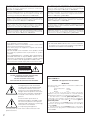
WARNING:
• This apparatus must be earthed.
• Apparatus shall be connected to a mains socket outlet
with a protective earthing connection.
• The mains plug or an appliance coupler shall remain
readily operable.
• All work related to the installation of this product should
be made by qualified service personnel or system
installers.
• F o r P E R M A N E N T LY C O N N E C T E D APPARATUS
provided neither with an all-pole MAINS SWITCH nor an
all-all pole circuit breaker, the installation shall be carried
out in accordance with all applicable installation rules.
• The connections should comply with local electrical code.
CAUTION:
• An ALL-POLE MAINS SWITCH with a contact separation
of at least 3 mm in each pole shall be incorporated in
the electrical installation of the building.
CAUTION
RISK OF ELECTRIC
SHOCK DO NOT OPEN
CAUTION: TO REDUCE THE RISK OF ELECTRIC SHOCK,
DO NOT REMOVE COVER (OR BACK).
NO USER-SERVICEABLE PARTS INSIDE.
REFER SERVICING TO QUALIFIED SERVICE PERSONNEL.
FOR YOUR SAFETY PLEASE READ THE FOLLOWING
TEXT CAREFULLY.
WARNING: This apparatus must be earthed.
IMPORTANT
The lightning flash with arrowhead
symbol, within an equilateral triangle,
is intended to alert the user to the
presence of uninsulated "dangerous
voltage" within the product's enclosure
that may be of sufficient magnitude to
constitute a risk of electric shock to
persons.
The exclamation point within an
equilateral triangle is intended to alert
the user to the presence of important
operating and maintenance (servicing)
instructions in the literature
accompanying the appliance.
Turn the power off at the mains to disconnect the main
power for all unit.
2
The wires in this mains lead are coloured in accordance with
the following code.
Green-and-yellow: Earth
Blue:
Neutral
Brown:
Live
As the colours of the wire in the mains lead of this
appliance may not correspond with the coloured markings
identifying the terminals in your plug, proceed as follows.
The wire which is coloured green-and-yellow must be
connected to the terminal in the plug which is marked with
the letter E or by the earth symbol
or coloured green or
green-and-yellow.
The wire which is coloured blue must be connected to the
terminal in the plug which is marked with the letter N or
coloured black.
The wire which is coloured brown must be connected to
the terminal in the plug which is marked with the letter L or
coloured red.
Contents
Important safety instructions . . . . . . . . . . . . . . . . . . . . . . . . . . . . . . . . . . . . . . . . . . . . . . . . . . . 4
Limitation of liability . . . . . . . . . . . . . . . . . . . . . . . . . . . . . . . . . . . . . . . . . . . . . . . . . . . . . . . . . . 5
Disclaimer of warranty . . . . . . . . . . . . . . . . . . . . . . . . . . . . . . . . . . . . . . . . . . . . . . . . . . . . . . . . 5
Preface . . . . . . . . . . . . . . . . . . . . . . . . . . . . . . . . . . . . . . . . . . . . . . . . . . . . . . . . . . . . . . . . . . . 5
Features . . . . . . . . . . . . . . . . . . . . . . . . . . . . . . . . . . . . . . . . . . . . . . . . . . . . . . . . . . . . . . . . . . . 6
About the user manuals . . . . . . . . . . . . . . . . . . . . . . . . . . . . . . . . . . . . . . . . . . . . . . . . . . . . . . 6
Trademarks and registered trademarks . . . . . . . . . . . . . . . . . . . . . . . . . . . . . . . . . . . . . . . . . . 6
Precautions . . . . . . . . . . . . . . . . . . . . . . . . . . . . . . . . . . . . . . . . . . . . . . . . . . . . . . . . . . . . . . . . 7
Major operating controls . . . . . . . . . . . . . . . . . . . . . . . . . . . . . . . . . . . . . . . . . . . . . . . . . . . . . 9
Precautions for installation . . . . . . . . . . . . . . . . . . . . . . . . . . . . . . . . . . . . . . . . . . . . . . . . . . . 10
DIP switch settings . . . . . . . . . . . . . . . . . . . . . . . . . . . . . . . . . . . . . . . . . . . . . . . . . . . . . . . . . 12
■ Communication Parameters (DIP Switch 2) . . . . . . . . . . . . . . . . . . . . . . . . . . . . . . . . . . . 12
■ Unit Number (DIP Switch 1) . . . . . . . . . . . . . . . . . . . . . . . . . . . . . . . . . . . . . . . . . . . . . . . 13
■ RS485 Communication Parameters (DIP Switch 1) . . . . . . . . . . . . . . . . . . . . . . . . . . . . . 15
Installation . . . . . . . . . . . . . . . . . . . . . . . . . . . . . . . . . . . . . . . . . . . . . . . . . . . . . . . . . . . . . . . . 16
■ Mounting the Camera . . . . . . . . . . . . . . . . . . . . . . . . . . . . . . . . . . . . . . . . . . . . . . . . . . . . 16
Connections . . . . . . . . . . . . . . . . . . . . . . . . . . . . . . . . . . . . . . . . . . . . . . . . . . . . . . . . . . . . . . 20
Troubleshooting . . . . . . . . . . . . . . . . . . . . . . . . . . . . . . . . . . . . . . . . . . . . . . . . . . . . . . . . . . . . 22
Specifications . . . . . . . . . . . . . . . . . . . . . . . . . . . . . . . . . . . . . . . . . . . . . . . . . . . . . . . . . . . . . 26
Standard accessories . . . . . . . . . . . . . . . . . . . . . . . . . . . . . . . . . . . . . . . . . . . . . . . . . . . . . . . 27
Optional accessories . . . . . . . . . . . . . . . . . . . . . . . . . . . . . . . . . . . . . . . . . . . . . . . . . . . . . . . . 27
3
Important safety instructions
1) Read these instructions.
2) Keep these instructions.
3) Heed all warnings.
4) Follow all instructions.
5) Clean only with dry cloth.
6) Do not block any ventilation openings. Install in accordance with the manufacturer's instructions.
7) Do not install near any heat sources such as radiators, heat registers, stoves, or other apparatus (including
amplifiers) that produce heat.
8) Do not defeat the safety purpose of the polarized or grounding-type plug. A polarized plug has two blades with
one wider than the other. A grounding type plug has two blades and a third grounding prong. The wide blade or
the third prong are provided for your safety. If the provided plug does not fit into your outlet, consult an
electrician for replacement of the obsolete outlet.
9) Protect the power cord from being walked on or pinched particularly at plugs, convenience receptacles, and the
point where they exit from the apparatus.
10) Only use attachments/accessories specified by the manufacturer.
11) Use only with the cart, stand, tripod, bracket, or table specified by the manufacturer, or sold with the apparatus.
When a cart is used, use caution when moving the cart/apparatus combination to avoid injury from tip-over.
S3125A
12) Unplug this apparatus during lightning storms or when unused for long periods of time.
4
Limitation of liability
THIS PUBLICATION IS PROVIDED "AS IS" WITHOUT WARRANTY OF ANY KIND, EITHER EXPRESS OR IMPLIED,
INCLUDING BUT NOT LIMITED TO, THE IMPLIED WARRANTIES OF MERCHANTABILITY, FITNESS FOR ANY
PARTICULAR PURPOSE, OR NON-INFRINGEMENT OF THE THIRD PARTY'S RIGHT.
THIS PUBLICATION COULD INCLUDE TECHNICAL INACCURACIES OR TYPOGRAPHICAL ERRORS. CHANGES
ARE ADDED TO THE INFORMATION HEREIN, AT ANY TIME, FOR THE IMPROVEMENTS OF THIS PUBLICATION
AND/OR THE CORRESPONDING PRODUCT (S).
Disclaimer of warranty
IN NO EVENT SHALL Panasonic System Networks Co., Ltd.BE LIABLE TO ANY PARTY OR ANY PERSON, EXCEPT
FOR REPLACEMENT OR REASONABLE MAINTENANCE OF THE PRODUCT, FOR THE CASES, INCLUDING BUT NOT
LIMITED TO BELOW:
(1) A NY DAMAGE AND LOSS, INCLUDING WITHOUT LIMITATION, DIRECT OR INDIRECT, SPECIAL,
CONSEQUENTIAL OR EXEMPLARY, ARISING OUT OF OR RELATING TO THE PRODUCT;
(2) PERSONAL INJURY OR ANY DAMAGE CAUSED BY INAPPROPRIATE USE OR NEGLIGENT OPERATION OF THE
USER;
(3) UNAUTHORIZED DISASSEMBLE, REPAIR OR MODIFICATION OF THE PRODUCT BY THE USER;
(4) INCONVENIENCE OR ANY LOSS ARISING WHEN IMAGES ARE NOT DISPLAYED, DUE TO ANY REASON OR
CAUSE INCLUDING ANY FAILURE OR PROBLEM OF THE PRODUCT;
(5) ANY PROBLEM, CONSEQUENTIAL INCONVENIENCE, OR LOSS OR DAMAGE, ARISING OUT OF THE SYSTEM
COMBINED BY THE DEVICES OF THIRD PARTY;
(6) ANY CLAIM OR ACTION FOR DAMAGES, BROUGHT BY ANY PERSON OR ORGANIZATION BEING A PHOTOGENIC
SUBJECT, DUE TO VIOLATION OF PRIVACY WITH THE RESULT OF THAT SURVEILLANCE-CAMERA'S PICTURE,
INCLUDING SAVED DATA, FOR SOME REASON, BECOMES PUBLIC OR IS USED FOR ANY PURPOSE;
(7) LOSS OF REGISTERED DATA CAUSED BY ANY FAILURE.
Preface
This color CCTV camera is a video surveillance device that incorporates a ¼-type CCD, a 36x zoom lens, preset and
pan and tilt capabilities in a dome configuration.
5
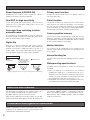
Features
Super Dynamic 6 (SUPER-D6)
Privacy zone function
SUPER-D6 can capture clear images of subjects
whose illumination is extremely different.
The privacy zone function can mask specific areas of
the scene from view.
New DSP for high sensitivity
Patrol function
A new noise reduction system lowers minimum illuminance to 0.5 lx in the color mode and 0.04 lx in the
black-and-white mode.
The patrol function can store manual camera movement routines for automatic playback. For example,
you can set the camera the movements of the people
to be monitored, by replaying the stored parameters
complicated movements are done automatically.
Auto night time switching to blackand-white mode
The camera can be configured to switch to the blackand-white mode automatically under low light conditions for clear images, even at night.
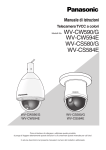
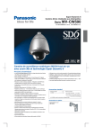
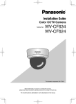
Digital flip
Normally, a camera needs to stop when it points
straight down during a tilt operation. With digital flip,
however, the camera is able to tilt from 0° to 180° in a
single motion. This makes it possible to track subjects
passing directly under the camera more smoothly.
The system can be configured with up to 256 camera
positions. A particular camera position can be selected
and viewed by entering the applicable preset number
on the system controller 10-key pad.
Motion detection
The system can be configured so any motion on the
monitor screen during surveillance causes output of an
alarm signal.
Internal heating fan
Digital Flip Operation
Tilting
downwards.
Camera position memory
The picture is flipped
when the camera is
pointing straight down
(at around 135°).
Tilting upwards.
Prevents snow and frost from building up on the dome
cover.*1
Waterproofing specifications
Outdoor enclosure based on IP66* 2 of IEC60529
standard.
Digital flip is performed only when the system controller joystick is held downwards.
*1 D oes not operate in environments with ambient
temperatures under -50 °C. In environments over -50 °C
defrosting may not function if wind and snow are too
strong. Use it with the power on continuously to keep
the temperature inside the camera over -10 °C.
*2 W
aterproof structure resistant to powerful jetting as
classified by the International Protection code.
About the user manuals
The operating instructions of the camera consist of 2
sets: this book and operating instructions (PDF).
This book explains how to install the camera.
Refer to the "Operating Instructions (PDF)" on the provided CD-ROM for descriptions of how to perform the
unit settings. Adobe® Reader® is required to read PDF.
When the Adobe® Reader® is not installed on the PC,
download the latest Adobe® Reader® from the Adobe
web site and install it.
Trademarks and registered trademarks
Adobe and Reader are either registered trademarks or
trademarks of Adobe Systems Incorporated in the
United States and/or other countries.
6
Precautions
The following points as well as the contents of "Warning"
and "Caution" shall be observed.
Refer installation work to the dealer.
Installation work requires technique and experiences.
Otherwise injury, or damage to this product may result.
Be sure to consult the dealer.
Do not insert any foreign objects.
This could permanetly damage this product. Turn the
power off immediately and contact qualified service
personnel for service.
Do not attempt to disassemble or modify this
product.
Failure to observe this may cause fire or electric shock.
Consult the dealer for the repair or inspections.
Stop operation immediately when something is
wrong with this product.
When smoke goes up from this product or the smell
of smoke comes from this product, continued use will
result in fire, injury, or damage to the product.
Turn the power off immediately and contact qualified
service personnel for service.
Select an installation area that can support the total
weight.
Selecting an inappropriate installation surface may
cause the product to fall down or topple over, resulting
in injury.
Installation work shall be started after sufficient
reinforcement.
Do not damage the power cable.
Do not damage, fabricate, twist, stretch, bundle, or
forcibly bend the power cable. Do not place heavy
objects. Keep away from heat sources.
Use of the damaged power cable may cause electric
shock, short circuit, or fire.
Consult the dealer for repair.
Do not install this product on a place that is greatly
influenced by wind.
Installation on a place where the wind speed is 40 m/s
or more per second may cause a fall of the product
resulting in injury or accidents.
This product shall be installed in a vibration-free
place.
Failure to observe this may cause screws and bolts to
be loosened and consequently to fall resulting in injury.
Install this product high enough to ensure that
people don't hit their heads.
Failure to observe this may cause a drop resulting in
injury or accidents.
Do not strike or give a strong shock to this product.
Failure to observe this may cause injury or fire.
Turn the power off when do wiring of this product.
Failure to observe this may cause electric shock. In
addition short circuit or wrong wiring may cause fire.
Do not use this product in an atmosphere of
flammable gases.
Periodic inspections shall be conducted.
Failure to observe this may cause injury by explosion.
Rust on the metal parts or screws may cause the
product to fall down resulting in injury or accidents.
Consult the dealer for the inspections.
Avoid installing this product in locations where it is
subject to damage by salt or corrosive gas.
The measures of protection against a fall of this
product shall be taken.
Failure to observe this may cause a drop resulting in
injury or accidents.
Do not touch the main body while this product is
panning/tilting.
Fingers may be caught up in the moving part, and that
may result in injury.
Do not hang down from this product or use this
product as a pedestal.
Failure to observe this may cause injury or accidents.
Otherwise the mounting fixtures will deteriorate, causing
the product to fall down and leading to accidents.
Use the specified mount bracket.
Failure to observe this may cause a drop resulting in
injury or accidents.
Do not rub the edges of metal parts with your hand.
Failure to observe this may cause injury.
Tighten screws and mounting fixtures to the
specified torque.
Failure to observe this may cause a drop resulting in
injury or accidents.
7
[Precautions for use]
Cleaning this product body
This product has no power switch.
When turning off the power, turn off a circuit breaker.
Turn the power off when cleaning this product. Do
not use strong abrasive detergent when cleaning this
product. Otherwise, it may cause discoloration.
To keep on using with stable performance
About the self-diagnosis function
Parts of this product may deteriorate and it may shorten
the lifetime of this product when using in locations subject
to high temperatures and high humidity.
Do not expose this product to direct heat sources such
as a heater.
When this product malfunctions due to exogenous
noise, etc. for 30 seconds or more, the product will
automatically reset and will return to normal state. When
the product is reset, initialization will be carried out
as when the power of the product is turned on. When
the product repeatedly resets, exogenous noise level
around the product may be high and that may cause
malfunction. Contact your dealer for instructions.
Handle this product with care.
Do not drop this product, nor apply shock or vibration
to this product.
Failure to observe this may cause trouble.
Do not touch the dome cover with your bare hands.
A dirty dome cover causes deterioration of picture
quality.
What to do if "WARMING UP, PLEASE WAIT."
appears on the display.
This message indicates that the temperature inside the
camera has become extremely low.
In such a case, wait until the heater unit of the camera
raises the internal temperature (for around 2 hours or
more in low temperatures below –10 ºC), and turn on
the power again.
What to do if "CAMERA TEMP. TOO COLD. POWER
ON AT -30 DEG C (-22 DEG F) OR MORE." appears
on the display.
The ambient temperature is too cold.
Please turn on the power under the conditions where
the ambient temperature is above -30 °C.
Discoloration on the CCD color filter
When continuously shooting a bright light source
such as a spotlight, the color filter of the CCD may
have deteriorated and it may cause discoloration.
Even when changing the fixed shooting direction after
continuously shooting a spotlight for a certain period,
the discoloration may remain.
Do not aim this product at strong light sources.
A light source such as a spot light causes a blooming
(light bleeding) or a smear (vertical lines).
Smear
Blooming
8
Bright subject
Lens and pan/tilt head
If a lens and pan/tilt head are not performed for a long
period of time, the grease coating inside these parts
may become sticky. That may obstruct the parts from
moving. To prevent this, move the lens or pan/tilt head
periodically. Or perform position refresh periodically.
About the position refresh function
Noise may be produced or the preset positions may
become inaccurate after a long operation.
Execute the "REFRESH" operation periodically, the
camera position will be corrected, and it is also
recommended to clean the slip ring of the camera.
Refer to the operating instructions (PDF) for further
information.
Consumable parts
The following are consumables: Replace them in
accordance with their lives. Their lives vary depending
on use environment and conditions.
Lens unit, slip ring: Approx. 3.7 million operations
(Lifetime around 20000 hours is just an indication when
using the camera at +35 °C.)
Cooling fan (motor): around 52000 hours
Synchronous mode setting
Image synchronous mode of this camera indicates
internal synchronization (INT) only. Set the multiplex
vertical driver (VD2) as OFF when the camera is
connected to the system controller of the company.
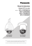
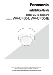
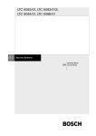
Major operating controls
Alarm Input
Connector
Alarm Output
Connector
Video Output
Connector
Data Port (RS485)
Camera Safety
Wire
Power Cable
TANT
INPOR
WARNING
Attachment Pipe
Front Sun Shield
(provided)
Housing Base
Rear Sun Shield
(provided)
OPEN
This part cannot
removed.
START
LOCK
LOCK
Sun Shield (pre-attached at factory)
Lens The lens cannot replaced.
Dome cover (do not remove)
Ensuring Trouble-free Operation
• This camera uses a "slip ring" for transmission of electrical power and signals. A dirty slip ring can cause
deterioration of picture quality during panning and generation of noise.
In order to ensure trouble-free camera operation, make sure that the cleaning function is turned on. Refer to the
operating instructions (PDF).
• If cleaning the slip ring does not eliminate poor picture quality and noise, it could mean that the slip ring has
reached the end of its service life. Contact a qualified service person or system installer to have it replaced.
9
Precautions for installation
The following points as well as the contents of
"Warning" and "Caution" shall be observed.
Panasonic assumes no responsibility for injuries or
property damage resulting from failures arising out
of improper installation or operation inconsistent
with this documentation.
Installation work shall be performed in accordance with
the technology standard of the electric installation.
Note:
• Select a place that is strong enough for the
installation. If you install the camera on a ceiling or
wall, except for accidents caused by fault in the
camera, Panasonic holds absolutely no
responsibility for accidents caused by the camera
falling due to unsuitable installation. Take sufficient
care when installing the camera. If the installation
is not strong enough, be sure to sufficiently
reinforce the location and check that it is safe.
• To prevent the camera from falling, attach the
safety wire to the mounting bracket or the anchor
bolt before starting to install the camera to prevent
it from falling.
• Always request installation work from a qualified
service person or system installer. Lack of technical
knowledge creates the risk of fire, electric shock,
personal injury, and material damage.
Installation Location
• Install the camera on a concrete ceiling or wall at a
location that is sufficiently strong to support it.
• For wall mounting, use the optionally available (WVQ122) Wall Mount Bracket.
• Bolts for mounting the ceiling mount Attachment
Pipe to a ceiling or wall are not provided. You need
to purchase them separately in accordance with the
materials and strength of the place you are
installing the camera.
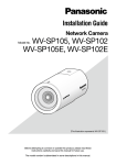
This camera is designed for use in a hanging configuration
only.
Install the camera in a horizontal configuration, with
the dome pointed downwards.
For wall mounting, use the optionally available (WV-Q122)
Wall Mount Bracket. Use the Screws recorded in the table
as below. Screws are not provided, and they should be
prepared in accordance with the materials, structure and
gross weight of the place you are installing the camera.
This
camera
Weight
Approx.
4.5 kg
10
Mounting conditions
Joint portion to ceiling or
Applicable mount bracket
wall surface
Installation Recommen- Screw Minimum pull-out
Model Weight
position ded screw quantity strength (per 1 pc.)
Approx.
4
823 N
WV-Q122
On wall
M8
2 kg
pieces {84 kgf}
• Ensure that the mounting surface, anchor and
screws are sufficiently strong.
• Do not mount this product on a plaster board or a
wooden section because they are too weak. If this
product is unavoidably mounted on such a section,
the section shall be sufficiently reinforced.
Avoid installing this product in the following locations.
• Locations where a chemical agent is used such as
a swimming pool.
• Locations subject to steam and oil smoke such as a
kitchen, Locations near flammable gas or vapor.
• Locations where radiation or x-ray emissions are
produced.
• Locations where corrosive gas is produced,
Locations where it may be damaged by briny air
such as seashores.
• Locations where the temperature is not within
–50 °C to +50 °C.
• Locations subject to vibrations (This product is not
designed for on-vehicle use.)
• Locations subject to condensation as the result of
severe changes in temperature (In case of installing
the product in such locations, the dome cover may
become foggy or condensation may be caused on
the cover.)
Avoid moist or dusty places to install this product.
Otherwise, lifetime of the internal parts may be
shortened.
Avoid installing this product in a place with a high
level of noise.
Installation near an air conditioner, an air cleaner, a
vending machine, or the like causes noise.
Remove the cover film from the dome section of the
dome cover after the installation is complete.
Be sure to remove this product if it is not in use.
Keep this product cable away from the lighting cable.
Conduct the power distribution work to keep a distance
of 1 m or more from the 220 V - 240 V power line. Or
conduct the electric conduit work separately.
Failure to observe this may cause noise.
Radio interference
When this product is used near TV/radio antenna,
strong electric field or magnetic field (near a motor or a
transformer), images may be distorted and noise sound
may be produced. In such a case, run the camera
cable through specialized steel conduit tubes.
Take notice of humidity.
Check before connection
Install this product when the humidity is low. If this
product is installed during rainfall or at a high humidity,
the inside may be exposed to moisture and the dome
cover may become foggy.
Compatibility of devices are restricted. Before
connections, check the ratings and dimensions of the
devices to be used.
Contact your dealer for details.
Locally procure the screws
Important hints to help with the installation
Screws are not supplied with this product. Prepare the
screws according to the material, structure, strength
and other factors of the mounting area and the total
weight of objects to be mounted.
A self-cleaning function is activated (PAN/TILT/ ZOOM/
FOCUS) when the camera is turned on.
Screw tightening
• The screws and bolts must be tightened with an
appropriate tightening torque according to the
material and strength of the installation area.
• Do not use an impact driver. Failure to observe
this may cause overtightening and consequently
damage to the screws.
• When a screw is tightened, make the screw at a right
angle to the surface. After tightening the screws or
bolts, perform visual check to ensure tightening is
enough and there is no backlash.
Heater unit
This product is equipped with an internal heater unit
for use in cold climates. The heater unit turns on
automatically when the temperature inside the product
drops below +10 °C. However, in an extremely lowtemperature environment below –30 °C, snow and frost
may not be defrosted from the dome cover. When using
this product in cold climates, take notice of the ambient
and internal temperatures of the product. When this
product is installed and operated in low temperatures
below –10 °C, normal images may not be obtained
immediately after startup. In such a case, wait around 2
hours or more, and turn on the power again.
Influence on images and their quality
This product has no wiper unit. Under the following
conditions, image quality may deteriorate or images
may not be viewed properly.
(1) Influence by rainfall
Due to the wind that accompanies rainfall, raindrops
may fall on the dome cover. That may make images
less viewable.
(2) Influence by snowfall
Due to the wind that accompanies snowfall, snow
may fall on the dome cover. That may partially make
surveillance images inviewable. (The extent of
inviewability may vary depending on the amount of
snowfall and the quality of snow.)
(3) Influence by dust in the air or gas emission from
vehicles
Depending on the installation environment, dome
cover may be dirty due to dust in the air or gas
emission from vehicles. That may degrade the
quality of images.
11
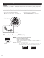
DIP switch settings
Important:
• Before setting up the camera for a configuration where the camera's data port (RS485) is used for camera control
(pan, tilt, etc.) by the system controller, the camera's DIP switches must be configured to specify the unit
number and communication parameters.
If DIP switch setting is not performed, the system controller control will not be possible and camera setup will
have to be performed again. Be sure to check the DIP switch settings before setting up the camera.
1. Attaching and removing the housing base
For removing the Housing Base, refer to pages 16 to
19.
2. Set the DIP switches as the following:
Communication parameters: Set with switch 2
Unit number: Set with switch 1
Camera top view
S
TA
T
R
L
o
k
c
ON
1
2
3
4
5
DIP
6
7
8
1
SW
ON
1
3
2
4
2
P
DI
SW
DIP Switch
■ Communication Parameters (DIP Switch 2)
The factory default settings are all OFF.
ON
1
2
3
4
Communication
Parameters
Terminator
Switch 1: Terminator (Internal Termination Resistance)
Set to ON in the following situations.
• When 1 camera is connected to this unit
• When 2 or more cameras are connected to this unit that works as a
termination
Switches 2 to 4: Communication Parameters
This setting toggles between 2-line and 4-line communication. Use
these switches to select the communication protocol being used.
ON
ON
1
2
3
4
4-line Communication
12
1
2
3
4
2-line Communication
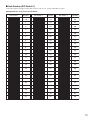
■ Unit Number (DIP Switch 1)
The factory default settings of these DIP switches are all OFF. (Coaxial Multiplex System)
Configuration for using Panasonic Protocol
DIP Switch 1
Unit
Number
2
3
4
5
6
7
8
1 ~ 96 *
ON
1
2
3
4
5
6
7
8
1
2
3
4
5
6
7
8
2
2
3
4
5
6
7
8
3
2
3
4
5
6
7
8
4
2
3
4
5
6
7
8
5
2
3
4
5
6
7
8
6
2
3
4
5
6
7
8
2
3
4
5
6
7
8
ON
1
2
3
4
5
6
7
8
ON
1
2
3
4
5
6
7
8
ON
1
2
3
4
5
6
7
8
ON
1
2
3
4
5
6
7
8
ON
1
2
3
4
5
6
7
8
2
3
4
5
6
7
8
ON
1
ON
1
2
3
4
5
6
7
8
ON
1
2
3
4
5
6
7
8
2
3
4
5
6
7
8
ON
1
ON
1
2
3
4
5
6
7
8
ON
1
2
3
4
5
6
7
8
2
3
4
5
6
7
8
ON
1
7
9
10
11
12
13
14
15
16
17
18
19
3
4
5
6
7
8
2
3
4
5
6
7
8
3
4
5
6
7
8
24
3
4
5
6
7
8
25
2
1
3
4
5
6
7
8
3
4
5
6
7
8
3
4
5
6
7
8
3
4
5
6
7
8
2
3
4
5
6
7
8
2
3
4
5
6
7
8
ON
1
2
3
4
5
6
7
8
ON
1
2
3
4
5
6
7
8
ON
1
2
3
4
5
6
7
8
ON
1
2
3
4
5
6
7
8
ON
1
2
3
4
5
6
7
8
2
3
4
5
6
7
8
ON
1
ON
1
2
3
4
5
6
7
8
ON
1
2
3
4
5
6
7
8
2
3
4
5
6
7
8
ON
1
ON
1
2
3
4
5
6
7
8
ON
1
3
4
5
6
7
8
69
2
3
4
5
6
7
8
2
3
4
5
6
7
8
ON
26
27
28
29
30
31
32
33
34
35
36
37
38
39
40
41
42
43
ON
44
2
3
4
5
6
7
8
2
3
4
5
6
7
8
ON
45
DIP Switch 1
1
3
4
5
6
7
8
70
1
2
3
4
5
6
7
8
71
1
3
4
5
6
7
8
72
1
6
7
8
46
2
3
4
5
6
7
8
47
2
3
4
5
6
7
8
48
1
2
3
4
5
6
7
8
49
1
2
3
4
5
6
7
8
50
1
2
3
4
5
6
7
8
2
3
4
5
6
7
8
2
3
4
5
6
7
8
2
3
4
5
6
7
8
2
3
4
5
6
7
8
2
3
4
5
6
7
8
2
3
4
5
6
7
8
2
3
4
5
6
7
8
2
3
4
5
6
7
8
2
3
4
5
6
7
8
2
3
4
5
6
7
8
2
3
4
5
6
7
8
2
3
4
5
6
7
8
2
3
4
5
6
7
8
2
3
4
5
6
7
8
2
3
4
5
6
7
8
2
3
4
5
6
7
8
2
3
4
5
6
7
8
51
1
52
1
ON
1
ON
1
ON
1
ON
1
ON
1
ON
1
ON
1
ON
1
ON
1
ON
1
ON
1
ON
1
ON
1
ON
1
ON
53
54
55
56
57
58
59
60
61
62
63
64
65
66
67
68
DIP Switch 1
Unit
Number
ON
2
3
4
5
6
7
8
78
1
2
3
4
5
6
7
8
87
2
3
4
5
6
7
8
88
2
3
4
5
6
7
8
89
2
3
4
5
6
7
8
90
ON
2
3
4
5
6
7
8
79
1
ON
2
3
4
5
6
7
8
80
1
ON
ON
2
1
Unit
Number
ON
ON
1
1
ON
2
5
ON
ON
1
4
ON
2
1
3
ON
2
1
2
ON
2
1
1
ON
ON
2
ON
1
1
Unit
Number
ON
1
8
ON
2
1
ON
1
1
Unit
Number
ON
2
1
22
DIP Switch 1
1
1
1
21
2
ON
1
8
20
ON
1
7
ON
ON
1
6
ON
ON
1
5
ON
ON
1
4
ON
ON
1
3
ON
ON
1
2
ON
ON
1
1
DIP Switch 1
ON
23
ON
ON
1
Unit
Number
ON
ON
1
DIP Switch 1
2
3
4
5
6
7
8
81
1
13
22
1
2
3
4
5
6
7
Unit
Number
DIP Switch 1
ON
1
3
4
5
6
7
69
8
2
3
4
5
6
7
70
8
2
3
4
5
6
7
71
8
2
3
4
5
6
7
72
8
2
3
4
5
6
7
73
8
2
3
4
5
6
7
74
8
2
3
4
5
6
7
75
8
1
1
1
1
1
1
2
3
4
5
6
7
76
8
2
3
4
5
6
7
77
8
1
3
4
5
6
7
78
8
3
4
5
6
7
8
Unit
Number
DIP Switch 1
1
2
3
4
5
6
7
8
87
2
3
4
5
6
7
8
88
2
3
4
5
6
7
8
89
2
3
4
5
6
7
8
90
2
3
4
5
6
7
8
91
2
3
4
5
6
7
8
2
3
4
5
6
7
8
2
3
4
5
6
7
8
2
3
4
5
6
7
8
ON
2
3
4
5
6
7
79
8
1
ON
2
3
4
5
6
7
80
8
1
ON
2
3
4
5
6
7
81
8
1
ON
2
3
4
5
6
7
82
8
1
ON
2
3
4
5
6
7
83
8
1
92
ON
2
3
4
5
6
7
84
8
1
93
ON
2
3
4
5
6
7
85
8
ON
1
2
ON
2
ON
ON
1
Unit
Number
DIP Switch 1
1
68
1
8
ON
ON
1
7
ON
ON
1
6
ON
ON
1
5
ON
ON
1
4
ON
ON
1
3
ON
ON
1
2
ON
2
ON
1
45
1
8
2
3
4
5
6
7
86
8
1
94
ON
1
95
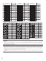
Configuration for using Pelco protocol
Unit Number
Pelco-P
Unit Number
Pelco-D
Unit Number
Pelco-P
Unit Number
Pelco-D
Unit Number
Pelco-P
1
12
23
2
13
24
3
14
25
4
15
26
5
16
27
6
17
28
7
18
29
8
19
30
9
20
31
10
21
32
11
22
Unit Number
Pelco-D
Important:
• When using Pelco protocol, make sure that the system works properly before use. Some functions using Pelco
protocol may be restricted when this camera and the apparatuses (commercially available) compatible with
Pelco protocol operate together.
Note:
• When using the Unit Number 1 to 96 of Panasonic Protocol and using the Unit Number 32 to 96 of Pelco-D
protocol, the unit number setting needs to be configured using the RS485 SET UP menu. For details about
configuring this setting, refer to the operating instructions (PDF).
• Turning on power when this setting is selected causes the RS485 SET UP menu to appear during the initialisation
routine.
14
■ RS485 Communication Parameters (DIP Switch 1)
Configuring DIP Switch 1 as shown below resets communication parameters to their factory default settings. You can
then change the settings as desired.
DIP Switch 1
ON
1
2
3
4
5
6
7
8
2
3
4
5
6
7
8
2
3
4
5
6
7
8
2
3
4
5
6
7
8
2
3
4
5
6
7
8
ON
1
ON
1
ON
1
ON
1
Setting Description
This setting resets communication parameters to the factory default settings.
BAUD RATE : 19 200 bit/s, DATA BIT : 8 bit, PARITY CHECK : NONE, STOP BIT : 1 bit
BAUD RATE : 9 600 bit/s, DATA BIT : 8 bit, PARITY CHECK : NONE, STOP BIT : 1 bit
BAUD RATE : 4 800 bit/s, DATA BIT : 8 bit, PARITY CHECK : NONE, STOP BIT : 1 bit
BAUD RATE : 2 400 bit/s, DATA BIT : 8 bit, PARITY CHECK : NONE, STOP BIT : 1 bit
Perform the following steps to use this setting.
(1) Turn off the camera and use DIP Switch 1 to configure RS485 communication parameters as shown above.
(2) Turn on the camera.
This applies the setting you configured in step (1).
(3) Turn off the camera, use DIP Switch 1 to set the unit number (☞ pages 13 and 14), and then turn the camera
back on again.
15
Installation
Precautions
• Make sure that the place you are installing the camera is strong enough to support it. If it is not strong enough,
then the camera may fall and hurt someone.
• The following steps of installation and connection work should be done by qualified service personnel or
system installers and should conform to all local codes.
• Be sure to turn the power off before installation and connection.
• Do not install the camera near the air outlet of an air conditioner.
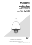
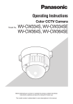
■ Mounting the Camera
Wall mount
The figure shows an example of the camera mounted on
a wall with the optional WV-Q122 Wall Mount Bracket.
See instructions included with the optional bracket
STEP 1
Attach the camera to the housing base, and secure the
camera and the housing base with the mounting
screws (x3).
The screws that are removed need to be used during
reassembly. Be careful to not lose them.
* Special screw (mounting screw)
Use a hexagon wrench for the hexagon screw (M5).
Screws (x3)
Important:
• When using this mount bracket, the hexagon screws
(M6) that are accessory of the brackets cannot be
used as the mounting screws for this camera. Use
the hexagon screws (M5) attached to the housing
base.
Housing Base
REAR
START
LOCK
Camera
Ceiling mount
The figure shows an example of the camera mounted
on a ceiling with a locally procured bracket.
Refer to the instructions included with the bracket for
filling gaps and holes with waterproof material.
Note:
• When removing the front and rear sun shields,
perform steps 5 to 7 in the reverse order.
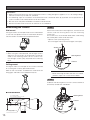
STEP 2
To detach the housing base, turn the camera clockwise
to the end, viewed from the bottom.
● Construction
40 1-1/2B deep 30 MAX
PT11 crest (taper pipe thread)
Housing Base
300 mm
REAR
Camera
(Ø 58)
START
40 1-1/2A deep 30 MAX
PT11 crest (parallel pipe thread)
16
(60)
85
25
LOCK
STEP 3
STEP 6
emove the attachment pipe from the housing base by
R
loosening 4 screws.
*S
pecial screw (mounting screw): Use a hexagon
wrench for the hexagon screw (M6).
Fix the housing base to the attachment pipe.
• Fasten 4 screws (the screws that were removed in
step 3) making sure that "REAR" engraved on the
housing base faces the wall.
(Recommended tightening torque: 2.45 N·m {25 kgf·cm})
• Fill the gap between the bracket and attachment
pipe with waterproof material such as silicon clay.
See instructions of the bracket for details.
Important:
• Carefully apply the sealing so that water or
moisture cannot get inside. If water gets
inside the camera it could cause a shock or
fire. Also, if moisture gets inside the camera it
could cause the dome to become foggy.
x4 Screws
Waterproof Material
x4 Screws
STEP 4
(1) Fix the bracket to the installation surface using
appropriate bolts, nuts or the like (not supplied).
Housing Base
REAR
REAR
STEP 7
Attachment Pipe
(2) Fix the attachment pipe to the bracket.
(1) Check that the projection of the leaf spring on the
top of the camera is at the "START" position. If the
projection is not at the "START" position, turn the
plate clockwise to match it to the "START" position.
Leaf Spring
Bending
STEP 5
Thread cables through the bracket. Connect the cables
to the camera (☞ page 20).
Warning:
•Seal the cables with plastic or rubber tape to
prevent it from being exposed.
Plate
Cables
Housing Base
17
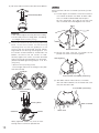
(2) Be sure to hook the camera safety wire into the bracket.
Camera Safety Wire
STEP 8
Attach the front and rear sunshields (accessory) to the
camera.
(1) Put the fingers on the dents of the front and rear
sun-shields to detach the hooks on both sides.
The sun-shield will be divided into two parts.
For loss prevention, one side of the front and
rear sunshields are linked together with a wire.
Dents
Important:
• Give sufficient length to the safety wire when installing.
• Fix the safety wire to a strong place, considering
the weight of the camera (4.5 kg).
(3) Install the camera to the housing mounting
base. Install the camera to the housing
mounting base so that the guide pin at the
camera top will be directed toward "REAR"
engraved on the housing mounting base. Turn
the camera counter-clockwise, viewed from the
bottom, to confirm that the camera is fixed.
Securely tighten the screws* that were removed
when the housing mounting base was removed.
(Recommended tightening torque: 2.45 N·m
{25 kgf·cm})
* Special screw (mounting screw)
Use a hexagon wrench for the hexagon screw (M5).
View from the top
Guide pin
Wire
Detach the hooks.
(2) Locate the front and rear sunshields to the
position that covers the housing base.
Housing Base
START
LOCK
Front and rear sunshields (accessory)
When camera is installed
x3 Screws
When fixed
(3) Joint both sides of front and rear sunshields.
Joint the hook and dents on the linked side, and
then joint the other side.
Front and rear sunshields (accessory)
Housing Base
Main sunshield
REA
R
Guide Pin
Camera
START
LOCK
Poorly tightened screws may result in water
leaking into the camera or possible fire.
18
Safety wire
Important:
• Joint both sides of the front and rear sunshields
before fitting in the main sunshield.
• Do not trap the safety wire inside.
• The safety wire is designed to support only the
weight of the camera when the camera falls.
Do not put an excessive weight that the safety
wire cannot support.
STEP 9
Fit the front and rear sunshields in the main sunshield.
• Align " " of the rear sunshield to " START" of the
main sunshield. Then, turn the front and rear
sunshields toward "LOCK" until a click is heard.
Front and rear sunshields (accessory)
Main sunshield
Align "
" to "
".
STEP 10
Fix the front and rear sunshields on the camera using
the front/rear sunshield fixing screw (accessory).
(Recommended tightening torque: 0.72 N·m)
Front and rear sunshields fixing screw (accessory)
Important:
• When the power of the camera is turned on,
the camera will start panning and the position
will automatically be initialized.
Note:
• When removing the front and rear sunshields,
perform steps 8 to 10 in the reverse order.
19
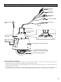
Connections
Precautions
• The following connections should be made by qualified service personnel or system installers in accordance
with all local codes.
• See the reverse side of the cover page for main lead connection.
• Turn off the power at the fuse box before starting the installation work, or it so could result in fire, electric shock,
personal injury, and material damage.
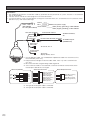
Brown (Live)
Blue (Neutral)
Green/Yellow
220 V - 240 V AC
(WV-CW590)
24 V AC (WV-CW594)
Data Port (RS485)
To the power supply
GND ( Safety grounding )*3 WV-CW590
GND ( Signal grounding )*3 WV-CW594
Twisted Pair Cable*1
To Matrix Switcher,
etc.
(RJ-12)
Video Output
Connector
Coaxial Cable RG-6/U (5C-2V)*2
(BNC)
To VIDEO IN port
(CAMERA IN)
Alarm Input
Connector
To sensor, etc.*4
Alarm Output
Connector
To buzzer,
display device, etc.*4
*1: For twisted pair cable, use shielded low-impedance cable with a thickness of at
least AWG#22 (0.33 mm2).
*2: Keep the overall length of coaxial cable under 1200 m (in the case of RG-6/U
(5C-2V)).
*3: Be sure to connect the grounding cable to ground.
*4: Since a female cable is not attached, cut off the connector and connect to the
twisted pair cable of the same type.
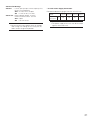
Alarm Input Connector
Data Port (RS485)
Data
Tx
Data
Rx
Red
T(B)
T(A)
R(B)
R(A)
Orange
Yellow
Green
(RJ-12)
Alarm In 1*5 (Black)
GND*5 (Brown)
Alarm In 2*5 (Red)
GND*5 (Orange)
Alarm In 3*6 (Yellow)
GND*6 (Green)
Alarm In 4*6 (Blue)
GND*6 (Violet)
*5: The type of twisted pair cable is AWG#28.
*6: The type of twisted pair cable is AWG#26.
20
Alarm Output Connector
Alarm Out 1*5 (Grey)
GND*5 (White)
Alarm Out 2*5 (Pink)
GND*5 (Light Green)
Alarm In/Out Ratings
Alarm In : 5 V DC pull-up input. Drive capacity of at
lease 0.2 mA required.
OFF:4 V to 5 V DC, or open
ON :1 V DC or less, or short
Alarm Out : Open collector output. 16 V DC,
maximum drive current: 100 mA
OFF:Open
ON :100 mA or less
Note:
• Do not turn off camera power within 30 seconds
after turning it on. Doing so can cause pan, tilt,
zoom, or focus to go out of position.
• 24 V AC Power Supply Connection
Recommended wire gauge sizes for 24 V AC line
Copper wire size
(AWG)
Length of
cable (approx.) (m)
#20
#18
#24
#22
(0.22mm2) (0.33mm2) (0.52mm2) (0.83mm2)
20
30
45
75
Important:
• The power supply of 24 V AC shall be insulated
against 220 to 240 V AC.
21
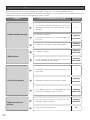
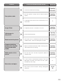
Troubleshooting
Before requesting service, check the following symptoms to see if you can solve the problem yourself.
If the countermeasures described below do not correct the problem, or if the symptoms you are experiencing are not
covered here, contact a quality service person or system installer.
Problem
Cause and Recommended Action
• Is the camera connected correctly? Check the
operating instructions that come with your system
controller.
No picture (dark screen)
• Is the lens iris closed?
Execute the iris reset from the system controller you
are using.
Reference Pages
—
Operating
Instructions
• Is the camera set up for a fixed shutter speed?
Operating
Instructions
• Is the lens iris open?
Operating
Instructions
• Is FIX selected for the electronic sensitivity
enhancement (SENS UP) setting?
Operating
Instructions
• Is the dome cover or lens of the camera dirty? If so,
clean them.
7
White picture
Out of focus picture
Digital noise in the
picture
• Is MANUAL selected for the auto focus mode?
Operating
Instructions
• Is the object one that is not compatible with auto
focus? For such objects, focus manually.
Operating
Instructions
• The slip ring may be dirty. Do you have the
cleaning function turned on?
Operating
Instructions
• Is the camera set up correctly?
22
10
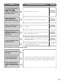
Problem
Poor picture color
Cause and Recommended Action
Reference Pages
• Check the white balance setting.
Operating
Instructions
• Use the special setup menu to adjust picture
quality.
Operating
Instructions
• Is the dome cover or lens of the camera dirty? If so,
clean them.
7
Image flicker
• If Super Dynamic 6 is turned on, turn it off.
Operating
Instructions
Afterimages in
the picture
• Check the DNR setting.
Operating
Instructions
Black-and-white picture
• The camera has an auto black-and-white switching
mode function. Check the setting of this mode.
Operating
Instructions
Frequent switching
between the color and
the black-and-white
modes
• Adjust the black-and-white mode switching level,
and the duration time setting.
Operating
Instructions
White specks in the
picture
• Use the PIX OFF function to perform blemish
compensation.
Operating
Instructions
• Is the camera connected correctly? See the
operating instructions that come with the system
controller you are using.
—
• Are camera communication settings configured
correctly?
12-15
20
Menu does not open.
23
Problem
Cause and Recommended Action
Reference Pages
Black line appears in
the image
• Whether or not the connected system controller is
set as multiplex vertical driver (VD2)?
Menu settings will not
change.
• Is the password lock function turned on?
I forgot the password.
• Contact a quality service person or system installer.
—
Picture does not
switch to black-andwhite.
• Switching is not performed when the ALARM IN 4
setting is BW. Check the setting.
Operating
Instructions
• Is the camera connected correctly? See the
operating instructions that come with the system
controller you are using.
—
• The camera has a pan limit function. Check the
PAN LIMIT settings.
Operating
Instructions
• The motor or lens may be worn. Contact a quality
service person or system installer.
—
Pan, tilt, zoom, or
focus do not work.
The camera movement
modes (OFF, SEQ,
SORT, AUTOPAN,
PATROL, AUTOTRACK)
do not work.
24
7
Operating
Instructions
• Check the self return function.
Operating
Instructions
• Check the ALARM IN settings.
Operating
Instructions
• Check the recover time setting of the motion
detector.
Operating
Instructions
Problem
The camera movement
mode (OFF, SEQ,
SORT, AUTOPAN,
PATROL, AUTOTRACK)
setting changes.
Cause and Recommended Action
Reference Pages
• Check the self return function.
Operating
Instructions
Camera position is
different from the
preset position setting.
• Perform REFRESH from the special setup menu.
Operating
Instructions
Picture is different from
the position setting.
• Adjust the picture using the preset menu and a
scene file.
Operating
Instructions
Upper part of the picture
is black when the
camera is in a horizontal
orientation.
• This is caused by the camera's internal cover. It
does not indicate malfunction.
Operating
Instructions
• If the cleaning function is turned on, this is normal
doe s n o t i nd i c a te m a lf u n c ti o n . C h e c k th e
CLEANING settings.
Operating
Instructions
• If the cleaning function is not turned on, this
symptom could be due to noise.
7, 10
Camera suddenly starts
to pan by itself.
● Periodically check the power cord.
Power cord sheathing is
damaged.
Power cord becomes
hot during operation.
• The power cord is damaged. Continued use creates the risk of
electric shock and fire. Immediately unplug the power plug and
contact a qualified service person or system installer for servicing.
Power cord becomes
warm or hot when it is
bent or stretched during
use.
25
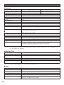
Specifications
● General
WV-CW590
Power Requirements
Power Consumption
Pick-up Device
Effective Pixels
Scanning Area
Signal
Synchronization
Scanning
Scanning Frequencies
Video Output
Resolution (Center)
Minimum Illumination
Dynamic Range
S/N Ratio
Ambient Operating Temperature
Water Resistance
Dimensions
Weight
Finish
WV-CW594
220 V - 240 V AC, 50 Hz
24 V AC, 50 Hz
80 W
98 W
1/4-type interline transfer CCD
976 (H) × 582 (V)
3.66 mm (H) × 2.73 mm (V)
PAL
Internal (INT)
2:1 interlace
Horizontal: 15.625 kHz, Vertical: 50.00 Hz
VBS: 1.0 V [p-p]/75 Ω (BNC plug)
Horizontal: 650 TV lines typ. (Center)
Vertical :400 TV lines minimum (Center)
0.5 lx (color mode)
0.04 lx (black-and-white mode)
SENS UP: OFF; AGC: HIGH
54 dB typ. (SUPER-D6: ON)
52 dB minimum (AGC: OFF)
-50 °C to +50 °C; Humidity 90 % max. (non-condensation)*1
IP66 protection from water jets from a nozzle (IEC60529)
229 mm (D) × 360 mm (H) diameter of the dome: 150 mm
Approx. 4.5 kg (including front and rear sunshields)
Camera: Die cast aluminium, coated (Paint color: Natural silver)
Sunshield*2: ASA resin, coated ( Paint color: Natural silver)
Dome: Clear polycarbonate resin
*1 When power is on continuously (however, the camera's interior temperature is -10 °C or higher)
*2 Sunshield cannot removed.
● Pan and Title
Panning Range
360° endless
Panning Modes
Manual, auto, manual position, sequential position
Manual: Approx. 0.065 °/s to 120 °/s 8 steps, 16 steps, 64 steps
Preset: Approx. 400 °/s
-5° to 185° (horizontal - vertical - horizontal)
Manual, manual position, sequential position
Manual: Approx. 0.065 °/s to 120 °/s 8 steps, 16 steps, 64 steps
Preset: Approx. 400 °/s
Panning Speed*2
Tilting Range
Tilting Modes
Tilting Speed*3
*3 Actual speed depends on type of controller being used.
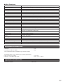
● Lens
26
Zoom Ratio
36x (Approx. 720x with digital zoom)
Focal Length
3.3 mm to 119 mm
Maximum Aperture Ratio
1:1.4 (WIDE) to 4.2 (TELE)
Object Distance
2.0 m
Iris Range
Angular Field of View
F1.4 to 22, Close
Horizontal: 1.7° (TELE) to 60.2° (WIDE)
Vertical: 1.3° (TELE) to 46.0° (WIDE)
● Main Functions
Controller Interface
Coaxial Multiplex System, RS485
Control Functions
AGC
Title (ID)
Zoom Speed
Zoom Limit
Password Lock
Auto Focus
Iris
Shutter
Electronic Sensitivity Enhancement
Auto Mode
Auto Pan Key
Digital Flip
SUPER-D6
VMD
Alarm Input/Output
Black-and-White Mode Switching
Privacy Zone
Patrol
Cleaning
Image Hold
Auto Image Stabilizer
Scene Select Setting
Language Setting
Pan and tilt, zoom and focus, 256 preset positions, home position, patrol
ON (LOW), ON (MID), ON (HIGH), OFF
ON, OFF (Preset ID, camera ID, area title: 16 alphanumeric characters)
around 6.0 seconds (TELE to WIDE) in manual mode
1x to 720x (Over 36x is digital zoom)
All menus
MANUAL/AUTO (PAN, TILT, ZOOM linked)
ALC (Adjustable OPEN/CLOSE output target level)/MANUAL
OFF (1/50), AUTO, 1/120, 1/250, 1/500, 1/1000, 1/2000, 1/4000, 1/10000
32X max. AUTO, 512X max. FIX
OFF, SEQ, SORT, AUTOPAN, PATROL, AUTOTRACK
SEQ, SORT, AUTOPAN, PATROL, AUTOTRACK
ON/OFF
ON/OFF
OFF/Motion Det/Scene Change
4 inputs (ALARM IN 1 to ALARM IN 4)
2 outputs (ALARM/AUX1, BW/AUX2)
AUTO/ON/OFF
ON/OFF (8 zone settings)
STOP/PLAY/LEARN
ON/OFF
ON/OFF
ON/OFF
INDOOR (L) /INDOOR (H) /OUTDOOR (L) /OUTDOOR (H)
Japanese, English, German, French, Italian, Spanish, Russian, Chinese
Standard accessories
CD-ROM* . . . . . . . . . . . . . . . . . . . . . . . . . . . . . . . . . . . . . . . . . . . 1 pc.
Installation Guide (this book) . . . . . . . . . . . . . . . . . . . . . . . . . . . . 1 pc.
*The CD-ROM contains the operating instructions (PDF).
The following parts are used during installation procedures.
Front and rear sunshields . . . . . . . . . . . . . . . . . . . . . . . . . . . . . . 1 pc. each
Front/rear sunshield fixing screw . . . . . . . . . . . . . . . . . . . . . . . . . 2 pcs. (incl. 1 spare)
Optional accessories
Wall Mount Bracket
WV-Q122
27
Information on Disposal for Users of Waste Electrical & Electronic Equipment (private
households)
This symbol on the products and/or accompanying documents means that used electrical and
electronic products should not be mixed with general household waste.
For proper treatment, recovery and recycling, please take these products to designated collection
points, where they will be accepted on a free of charge basis. Alternatively, in some countries you
may be able to return your products to your local retailer upon the purchase of an equivalent new
product.
Disposing of this product correctly will help to save valuable resources and prevent any potential
negative effects on human health and the environment which could otherwise arise from inappropriate waste
handling. Please contact your local authority for further details of your nearest designated collection point.
Penalties may be applicable for incorrect disposal of this waste, in accordance with national legislation.
For business users in the European Union
If you wish to discard electrical and electronic equipment, please contact your dealer or supplier for further
information.
Information on Disposal in other Countries outside the European Union
This symbol is only valid in the European Union.
If you wish to discard this product, please contact your local authorities or dealer and ask for the correct
method of disposal.
28
29
30
31
http://panasonic.net
Importer's name and address to follow EU rules:
Panasonic Testing Centre
Panasonic Marketing Europe GmbH
Winsbergring 15, 22525 Hamburg F.R.Germany
© Panasonic System Networks Co., Ltd. 2011
sL0311-2101
3TR006677CZA
Printed in China