1
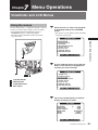
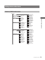
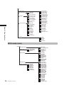
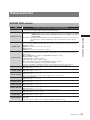
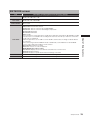
Panasonic Broadcast
AG-HPX500
Menu Information
7
Menu Operations
Chapter
Viewfinder and LCD Menus
Using the menus
Use the setup menus to change the settings to suit the
scenes you are shooting or what you are recording.
• If the thumbnail menu is displayed, press the
THUMBNAIL button to release the display.
• The menu items indicated in the blue characters
cannot be used.
1
When the unit is in other than playback
or recording mode, press the MENU
button.
• The function screen appears in the viewfinder
and on the LCD screen.
CAMERA MENU
PUSH MENU TO RETURN
1
2
Chapter 7 Menu Operations
1.SCENE FILE
2.CAMERA SETUP
3.SW MODE
4.RECORDING SETUP
5.AUDIO SETUP
6.OUTPUT SEL
7.DISPLAY SETUP
8.BATTERY SETUP
Use the JOG dial button (or the Up and
Down cursor buttons) to highlight the
function you want to change.
CAMERA MENU
2
3
1
2
3
4
2
1.SCENE FILE
2.CAMERA SETUP
3.SW MODE
4.RECORDING SETUP
5.AUDIO SETUP
6.OUTPUT SEL
7.DISPLAY SETUP
8.BATTERY SETUP
4
JOG dial button
MENU button
CURSOR buttons
SET button
PUSH MENU TO RETURN
3
Press the JOG dial button (or the SET
button) to display the items.
SW MODE
MID GAIN
HIGH GAIN
W.BAL.PRESET
USER MAIN
USER1
USER2
6dB
12dB
3.2K
SPOTLIGHT
GAIN
SLOTSEL
PUSH MENU TO RETURN
Viewfinder and LCD Menus
107
4
Use the JOG dial button (or the Up and
Down cursor buttons) to highlight the
item you want to change.
SW MODE
MID GAIN
HIGH GAIN
W.BAL.PRESET
USER MAIN
USER1
USER2
6dB
12dB
3.2K
SPOTLIGHT
GAIN
SLOTSEL
PUSH MENU TO RETURN
Chapter 7 Menu Operations
5
Use the JOG dial button (or the SET
button) to change the setting value.
SW MODE
MID GAIN
HIGH GAIN
W.BAL.PRESET
USER MAIN
USER1
USER2
6dB
12dB
3.2K
5.6K
GAIN
SLOTSEL
PUSH MENU TO RETURN
6
To change other settings, repeat steps
4 and 5.
• When you finish, press the MENU button to
return to the function screen.
7
To change other functions, repeat steps
2 to 5.
• To exit the function screen and return to the
normal screen, press the MENU button again.
108
Viewfinder and LCD Menus
Initializing the menu
settings
The menu settings contain both the user file settings
and the scene file settings. You can initialize them
separately.
To initialize the user file (i.e. all the
settings other than the scene file
settings)
Select INITIAL in USER FILE of the OTHER
FUNCTIONS screen. The current menu settings of
user file will return to the factory settings.
To initialize the scene file
From the 6 scene files, select the one you want to
initialize with the scene dial. Then in the SCENE FILE
screen, LOAD/SAVE/INIT, select INITIAL.
The settings for only the selected scene file are
returned to the factory settings.
• This does not effect the other scene files.
Setup menu structure
Camera (CAM) mode menu
CAMERA MENU
SCENE FILE
ASPECT CONV
SETUP
SW MODE
MID GAIN
HIGH GAIN
W.BAL.PRESET
USER MAIN
USER1
USER2
RECORDING SETUP
REC FORMAT
480i (576i) REC MODE
REC FUNCTION
ONE SHOT TIME
INTERVAL TIME
START DELAY
PREREC MODE
TC MODE
TC IN UB REGEN
UB MODE
AUDIO SETUP
OUTPUT SEL
CMPN/SDI SEL
SDI METADATA
SDI EDH
TC VIDEO SYNCRO
DISPLAY SETUP
ZEBRA DETECT
MARKER
SAFETY ZONE
DATE/TIME
LEVEL METER
ZOOM
CARD/BATT
P2CARD REMAIN
OTHER DISPLAY
LCD BACKLIGHT
LCD SET
SELF SHOOT
DOWNCON MODE
DISPLAY ASPECT
MENU BACK
Chapter 7 Menu Operations
CAMERA SETUP
LOAD/SAVE/INIT
OPERATION TYPE
FRAME RATE
SYNCRO SCAN
DETAIL LEVEL
V DETAIL LEVEL
DETAIL CORING
CHROMA LEVEL
CHROMA PHASE
COLOR TEMP Ach
COLOR TEMP Bch
MASTER PED
A.IRIS LEVEL
NEWS GAMMA
GAMMA
KNEE
MATRIX
SKIN TONE DTL
V DETAIL FREQ
NAME EDIT
FRONT VR CH1
FRONT VR CH2
MIC LOWCUT CH1
MIC LOWCUT CH2
MIC LOWCUT CH3
MIC LOWCUT CH4
LIMITER CH1
LIMITER CH2
LIMITER CH3
LIMITER CH4
AUTO LEVEL CH3
AUTO LEVEL CH4
25M REC CH SEL
TEST TONE
F.MIC POWER1
F.MIC POWER2
R.MIC POWER
F.MIC CH1 LEVEL
F.MIC CH2 LEVEL
R.MIC CH1 LEVEL
R.MIC CH2 LEVEL
HEADROOM
MONITOR MODE
Setup menu structure
109
BATTERY SETUP
Chapter 7 Menu Operations
CARD FUNCTIONS
SCENE FILE
USER FILE
SD CARD FORMAT
LENS MODE
SHADING SELECT
SHADING (USER)
CAC PROPERTY
CAC DATA READ
CAC DATA DELETE
CAC DATA INIT
IRIS ADJ
OTHER FUNCTIONS
USER FILE
1394 CONTROL
1394 CMD SEL
PC MODE
ACCESS LED
ALARM
SAVE LED
CLOCK SET
TIME ZONE
LANGUAGE
GL SELECT
GL PHASE
H PHASE
SYSTEM FREQ
VF ! LED
EXT DC IN SEL
BATTERY SELECT
BATTERY MODE
PROPAC14 NEAR
TRIMPAC14 NEAR
HYTRON50 NEAR
HYTRON140 NEAR
DIONIC90 NEAR
DIONIC140 NEAR
NP-L7 NEAR
ENDURA7 NEAR
ENDURA10 NEAR
ENDURA-D NEAR
PAG L95 NEAR
BP-GL65/95 NEAR
NICD14 NEAR
NICD14 END
TYPE A FULL
TYPE A NEAR
TYPE A END
TYPE B FULL
TYPE B NEAR
TYPE B END
NEAR END CANCEL
GAIN
WHITE
SHUTTER
FILTER
EXTENDER
MCR mode menu
MCR MENU
RECORDING SETUP
OUTPUT SEL
DISPLAY SETUP
DATE/TIME
LEVEL METER
CARD/BATT
P2CARD REMAIN
OTHER DISPLAY
LCD BACKLIGHT
LCD SET
DOWNCON MODE
DISPLAY ASPECT
MENU BACK
BATTERY SETUP
EXT DC IN SEL
BATTERY SELECT
BATTERY MODE
PROPAC14 NEAR
TRIMPAC14 NEAR
HYTRON50 NEAR
HYTRON140 NEAR
DIONIC90 NEAR
DIONIC140 NEAR
NP-L7 NEAR
ENDURA7 NEAR
ENDURA10 NEAR
ENDURA-D NEAR
PAG L95 NEAR
BP-GL65/95 NEAR
NICD14 NEAR
NICD14 END
TYPE A FULL
TYPE A NEAR
TYPE A END
TYPE B FULL
TYPE B NEAR
TYPE B END
NEAR END CANCEL
OTHER FUNCTIONS
110
Setup menu structure
CMPNT/SDI SEL
SDI METADATA
SDI EDH
MCR FORMAT
480i (576i) MCR MODE
1394 TC REGEN
TC MODE
1394 UB REGEN
UB MODE
USER FILE
PC MODE
ACCESS LED
SAVE LED
CLOCK SET
TIME ZONE
LANGUAGE
SYSTEM FREQ
Setup menu list
SCENE FILE screen
Item
LOAD/SAVE/INIT
Description of settings (Items in bold are factory settings.)
Saves, loads and initializes scene files (SD memory card)
----(No operation), LOAD (Load), SAVE (Save), INITIAL (Initialize)
FRAME RATE
Selects the shooting interval and exposure time when 720P and FILM CAM is selected. The default
values for the REC FORMAT 720/60, 720/30 and 720/24 are fixed at 60P, 30P and 24P, respectively.
●59.94Hz SYSTEM
DEFAULT, 12, 18, 20, 22, 24, 26, 30, 32, 36, 48, 60
●50Hz SYSTEM
DEFAULT, 12, 18, 20, 23, 25, 27, 30, 32, 37, 48, 50
SYNCRO SCAN
Adjusts the synchro scan shutter speed used for shooting images on a TV screen, etc. Turn and hold
the JOG dial button (operation button) upwards or downwards to increase the speed at which the set
values change.
●When VIDEO CAM is selected as the OPERATION TYPE option setting:
• 60P/60i: 1/60.0 ... 1/249.8
• 30P/30PN: 1/30.1 ... 1/48.0 ... 1/249.8
• 24P/24PA/24PN: 1/24.0 ... 1/48.0 ... 1/249.8
●When FILM CAM is selected as the OPERATION TYPE option setting:
• The shutter speed is displayed as an angle such as “180.0d.”
• 10.0 deg ... 180.0 deg ... 350.0 deg (the angle can be changed in increments of 0.5 degrees)
DETAIL LEVEL
Adjusts the level of the image outline correction (in the horizontal and vertical directions).
●Adjustable range: – 7 ... 0 ... + 7
V DETAIL LEVEL
Adjusts the level of outline correction in the vertical direction.
●Adjustable range: – 7 ... 0 ... + 7
DETAIL CORING
Adjusts the level of noise reduction of the detail signal.
●Adjustable range: – 2 ... 0 ... + 7
Set to – for a clearer image. Noise increases slightly. Set to + to reduce noise.
CHROMA LEVEL
Adjusts the chroma level.
●Adjustable range: – 7 ... 0 ... + 7
CHROMA PHASE
Makes fine adjustments to the chroma phase.
●Adjustable range: – 7 ... 0 ... + 7
Chapter 7 Menu Operations
Switches the shutter and frame rate operation to the video type or film type.
●VIDEO CAM: SYNCRO SCAN is set in 1/n increments. /The frame rate is dependent on the REC
FORMAT. /Slow shutter speeds are enabled. /Time code is displayed at 30 frames
except at 24PN.
OPERATION TYPE
●FILM CAM: SYNCRO SCAN is displayed as an angle./ FRAME RATE can be used to vary the frame
rate./Slow shutter speeds are disabled./ The time code indication is fixed at 24 hour
display.
Makes fine adjustments to the color temperature (after white balance adjustment of Ach).
COLOR TEMP Ach ●Adjustable range: – 7 ... 0 ... + 7
Makes fine adjustments to the color temperature (after white balance adjustment of Bch).
COLOR TEMP Bch ●Adjustable range: – 7 ... 0 ... + 7
MASTER PED
Adjusts the black master pedestal that serves as the video reference.
●Adjustable range: – 127 ... 0 ... + 127
A. IRIS LEVEL
Sets the desired AUTO IRIS level.
●Adjustable range: – 10 ... 0 ... + 10
NEWS GAMMA
Selects the news gamma curve. (Only valid for 1080i/60i, 50i, 720/50P, 50P, 480/60i and 576/50i)
●ON, OFF
Setting this function to ON also turns on ADSC (adaptable shading correction).
Setup menu list
111
Item
Description of settings (Items in bold are factory settings.)
GAMMA
Selects the gamma curves other than the news gamma curve.
●HD NORM: This gamma setting is suitable for HD shooting.
●LOW: Makes a mellow image using the gamma curve which has a gentle incline in lowbrightness
curve. The contrast sharpens.
●SD NORM: This is the normal video setting.
●HIGH: Expands the tone of dark parts and makes a brighter image using the gamma curve which has
a sharp incline in lowbrightness curve. The contrast softens.
●B.PRESS: Makes the contrast sharper than LOW.
●CINELIKE_D: Makes a cinema-like image.
●CINELIKE_V: Makes a cinema-like image with emphasized contrast.
When you select CINE-LIKE gamma, we recommend to set the lens aperture lower than normal image
level (approximately 1/2) to enjoy the full benefit of the function. (Disabled when gamma is ON.)
KNEE
Chapter 7 Menu Operations
MATRIX
To avoid overexposure, select the compression level (knee point) of the high intensity video signals
received through CCD.
●LOW: Low setting (Compression starts at approx. 80 %.)
●MID: Medium setting (Compression starts at approx. 90 %.)
●HIGH: High Setting (Compression starts at approx. 100 %.)
This setting cannot be changed when GAMMA is enabled and CINELIKE_D, V are selected.
Selects the MATRIX table suitable for the desired color expression during shooting.
●NORM1: Suitable for shooting in the open air or under a halogen lamp.
●NORM2: Suitable for brighter colors than the NORM1 mode.
●FLUO: Suitable for shooting under fluorescent light indoors.
●CINE-LIKE: Suitable for cinema-like image.
SKIN TONE DTL
Sets the skin tone details. Select ON to reduce the skin tone details and soften the skin tone.
●ON, OFF
V DETAIL FREQ
Sets the vertical detail for shooting in 480 24P, 24PA, 30P 576/25P mode.
●THIN: Makes the detail thin.
●MID: Makes the detail slightly thicker.
●THICK: Makes the detail thicker.
When images were shot in the progressive mode in which the vertical detail is set as “THIN” or “MID”
and are played on a monitoring television (60i interlace), you will see flickers caused on horizontal lines
and almost horizontal oblique lines. When playing back images in the progressive mode or when editing
images or performing other postprocessing, images with a higher resolution will be obtained with the
THIN or MID setting than with the THICK setting.
NAME EDIT
Edits the name of the selected scene file you have selected with the scene file dial.
CAMERA SETUP screen
Item
ASPECT CONV
SETUP
112
Setup menu list
Description of settings (Items in bold are factory settings.)
Selects the aspect ratio of the image you record in 480i format. This item cannot be selected when the
1080i or 720P recording format is used.
●SIDE-CROP (Side crop), LETTER BOX, SQUEEZE
Selects the setup level for the 480i video signal.
●0 %: Setup is switched to 0 % for both camera output and recording.
●7.5 %A: Setup is switched to 7.5 % for camera output and 0 % for recording.
SW MODE screen
Item
Description of settings (Items in bold are factory settings.)
MID GAIN
Sets the gain value assigned to the M position of the GAIN switch.
●0 dB, 3 dB, 6 dB, 9 dB, 12 dB
HIGH GAIN
Sets the gain value assigned to the H position of the GAIN switch.
●0 dB, 3 dB, 6 dB, 9 dB, 12 dB
W.BAL.PRESET
USER1
USER2
Selects the function assigned to the USER MAIN button.
●REC CHECK: Performs Rec Check.
●SPOTLIGHT: Auto iris control for the spotlight ON/OFF
●BACKLIGHT: Auto iris control for the backlight compensation
●BLACKFADE: Blackfade
●WHITEFADE: Whitefade
●GAIN: 18 dB:
• Press the button to set the gain value to 18 dB. This setting takes effect with the 60i and 60P recording
formats only. It is not valid when the recording frame rate is less than 22 fps or when the slow shutter
mode (1/15) is established.
• When the gain value is set to 18 dB or set from 18 dB to another value, the image can be disordered
for a moment.
• If the unit is being used in the MANUAL mode or AUTO mode, set the AGC item on the AUTO SW
screen of the setting menu to OFF to use this function.
●TEXT MEMO: Text memo recording
●SLOT SEL: Selects one of the P2 card slots.
●SHOT MARK: Shot mark recording
●LEV METER: Displays the level for channels other than those set in the menu.
●MARKER: Displays markers.
●LCD REV: Displays an upside down and reversed image on the LCD.
Selects the function assigned to the USER1 button. The settings are the same as USER MAIN above.
Selects the function assigned to the USER2 button. The settings are the same as USER MAIN above.
Setup menu list
Chapter 7 Menu Operations
USER MAIN
Sets the color temperature assigned to the PRST position of the WHITE BAL switch.
●3.2 K / 5.6 K
113
RECORDING SETUP screen
Item
REC FORMAT
480i (576i)
REC MODE
Description of settings (Items in bold are factory settings.)
Selects the recording format for P2 card.
●59.94Hz System: 1080i/60i, 1080i/30P, 1080i/24P, 1080i/24PA, 720P/60P, 720P/30P, 720P/24P,
720P/30PN, 720P/24PN, 480i/60i, 480i/30P, 480i/24P, 480i/24PA
●50 Hz System: 1080i/50i, 1080i/25P, 720P/50P, 720P/25P, 720P/25PN, 576i/50i, 576i/25P
Selects the 480i (576i) recording mode.
●DVCPRO50/DVCPRO DV
REC FUNCTION
Selects the special recording mode.
●NORMAL, INTERVAL, ONE SHOT, LOOP
ONE SHOT TIME
Selects the one-shot recording time.
●1F, 2F, 4F, 8F, 16F, 1s
INTERVAL TIME
Sets the interval time (INT) for interval recording (INTERVAL REC).
●2F, 4F, 8F, 16F, 1s, 2s, 5s, 10s, 30s, 1m, 5m, 10m
Chapter 7 Menu Operations
START DELAY
Sets the START delay time for INTERVAL REC and ONE SHOT REC.
PREREC MODE
Sets PRE RECORDING to ON or OFF. (Fixed to 3 seconds for HD and 7 seconds for SD)
●ON, OFF
TC MODE
TC IN UB REGEN
Selects the time code correction mode when recording the time code output by the internal time code
generator.
●DF: Uses the drop frame mode.
●NDF: Uses the non-drop frame mode.
The non-drop frame mode is used when a frame rate of 24P, 24PA, or 24PN is selected in a recording
format regardless of TC MODE setting.
Selects the user bits to be recorded when recording signals from a device connected to the TC IN
connector.
●ON: Records the user bits of the signal input to the TC IN connector.
●OFF: Records the user bits selected in the menu option UB MODE.
• Setting this option to ON prioritizes the input signal over the settings made in the menu option UB
MODE.
• No user bits are recorded when the input signal does not contain any user bits.
• Settings of the menu option UB MODE are used when no signal is input to the TC IN connector.
Set the content for user information.
●USER: Records the information of user.
●TIME: Records the time at recording.
●DATE: Records the date at recording.
●TCG: Records the values of the time code generator.
●FRM. RATE: Records the frame rate information for frame conversion.
a
UB MODE
114
Setup menu list
b
c
d
a: Checking information for user information
b: Frame sequence No.
• 0 to 4 are displayed in 24P/24P (ADV) mode.
• F is displayed in 60i/30P mode.
c: Frame rates
• Frame rate (60/30/24)
• I/P ID
• Conversion data
• Frame rate coefficient
d: Recording management data
• Frame update information
• REC START/STOP information
AUDIO SETUP screen
Item
FRONT VR CH1
FRONT VR CH2
MIC LOWCUT CH1
MIC LOWCUT CH3
MIC LOWCUT CH4
LIMITER CH1
LIMITER CH2
LIMITER CH3
LIMITER CH4
AUTO LEVEL CH3
AUTO LEVEL CH4
25M REC CH SEL
TEST TONE
F.MIC POWER1
F.MIC POWER2
R.MIC POWER
F.MIC CH1 LEVEL
F.MIC CH2 LEVEL
R.MIC CH1 LEVEL
R.MIC CH2 LEVEL
HEADROOM
MONITOR MODE
Setup menu list
Chapter 7 Menu Operations
MIC LOWCUT CH2
Description of settings (Items in bold are factory settings.)
Selects the function of the F. AUDIO LEVEL control of CH1 input.
●FRONT: The F. AUDIO LEVEL control controls FRONT1 input.
●REAR: The F. AUDIO LEVEL control controls REAR1 input.
●ALL: The F. AUDIO LEVEL control controls both FRONT1 and REAR1 inputs.
●OFF: The F. AUDIO LEVEL control does not control the input signal.
This control is disabled when the AUDIO SELECT CH1 switch is set to AUTO.
Selects the function of the F. AUDIO LEVEL control of CH2 input.
●FRONT: The F. AUDIO LEVEL control controls FRONT2 input.
●REAR: The F. AUDIO LEVEL control controls REAR2 input.
●ALL: The F. AUDIO LEVEL control controls both FRONT2 and REAR2 inputs.
●OFF: The F. AUDIO LEVEL control does not control the input signal.
This control is disabled when the AUDIO SELECT CH2 switch is set to AUTO.
Turns on and off the CH1 microphone lowcut filter.
●ON, OFF
Turns on and off the CH2 microphone lowcut filter.
●ON, OFF
Turns on and off the CH3 microphone lowcut filter.
●ON, OFF
Turns on and off the CH4 microphone lowcut filter.
●ON, OFF
Turns on and off the CH1 limiter.
●ON, OFF
Turns on and off the CH2 limiter.
●ON, OFF
Turns on and off the CH3 limiter.
●ON, OFF
Turns on and off the CH4 limiter.
●ON, OFF
Selects the method for selecting CH3 level.
●ON: Automatically controls CH3 level.
●OFF: Enables dial control of CH3 level via dial.
Selects the method for selecting CH4 level.
●ON: Automatically controls CH4 level.
●OFF: Enables dial control of CH4 level via dial.
Selects the audio channels to be recorded in the DVCPRO and DV formats.
●2CH: Only recorded on CH1 and CH2.
●4CH: Recorded on channels 1 to 4.
Selects the test signal.
●OFF: Disables test tone output.
●NORMAL: Outputs test tones to channels 1, 2, 3 and 4 when the OUTPUT/AUTO KNEE selector
switch is set to BARS and the AUDIO IN switch CH1 is set to FRONT.
●ALWAYS: Outputs test tones to channels 1, 2, 3 and 4 when the OUTPUT/AUTO KNEE selector
switch is set to BARS.
●CHSEL: Outputs test tones to channels where the AUDIO IN switch CH1 or CH2 is set to FRONT with
the OUTPUT/AUTO KNEE selector switch set to BARS.
Turns on and off the phantom power supply for the front microphone connected to CH1.
●ON, OFF
Turns on and off the phantom power supply for the front microphone connected to CH2.
●ON, OFF
Turns on and off the phantom power supply for the rear microphone.
●ON, OFF
Selects the input level for the front microphone connected to CH1.
●–40 dB, –50 dB, –60 dB
Selects the input level for the front microphone connected to CH2.
●–40 dB, –50 dB, –60 dB
Selects the input level for the rear microphone connected to CH1.
●–50 dB, –60 dB
Selects the input level for the rear microphone connected to CH2.
●–50 dB, –60 dB
Sets the headroom (standard level).
●59.94Hz System: 18 dB, 20 dB
●50 Hz System: 18 dB, 20 dB
Switches speaker and headphone audio delay.
●LIVE: No audio delay
●RECORDING: Recorded (delayed) audio
115
OUTUT SEL screen
Item
Description of settings (Items in bold are factory settings.)
CMPNT/SDI SEL
Selects D or SDI connector.
●59.94Hz system: 720P, 1080i, 480i
●50 Hz system: 720P, 1080i, 576i
SDI METADATA
Turns on and off metadata superimposition onto the HS-SDI signal.
●ON, OFF
SDI EDH
Turns on and off EDH superimposition onto the SD-SDI signal.
●ON, OFF
Selects whether to delay time code output.
TC VIDEO SYNCRO ●TC IN: Outputs the input from the TC IN connector without delay.
●VIDEO: Outputs the time code with delay according to the output video.
DISPLAY SETUP screen
Chapter 7 Menu Operations
Item
ZEBRA DETECT
MARKER
SAFETY ZONE
DATE/TIME
Description of settings (Items in bold are factory settings.)
Selects the brightness level of the leftleaning zebra patterns on the screen.
●50 %, 55 %, 60 %, 65 %, 70 %, 75 %, 80 %, 85 %, 90 %, 95 %, 100 %, 105 %
Select ON to display the marker.
●ON, OFF
To display the marker.
Sets SAFETY ZONE.
●OFF, 90 %, 4:3
Sets whether to display the date and time on the screen and whether to output from the VIDEO IN/OUT
jack.
●OFF: The date and time are not displayed.
●TIME: The time is displayed.
●DATE: The date is displayed.
●TIME&DATE: The time and date are displayed.
LEVEL METER
Select ON to display the audio level meter.
●ON, OFF
ZOOM
Turns zoom value display on and off.
●ON, OFF
Displays zoom values between Z00 to Z99.
CARD/BATT
Turns on and off card and battery remaining level.
●ON, OFF
P2CARD REMAIN
Switches the indication of remaining P2 memory card capacity.
●TOTAL: Indicates total remaining capacity of all cards.
●ONE CARD: Indicates the remaining capacity of the card that is being recorded.
OTHER DISPLAY
Select how much information to display on the screen.
●OFF, PARTIAL, ALL
LCD BACKLIGHT
Adjusts the backlight of the LCD monitor. Select HIGH for brighter backlight.
●HIGH, NORMAL
LCD SET
SELF SHOOT
Adjusts the display level of the images on the LCD monitor.
●LCD COLOR LEVEL, LCD BRIGHTNESS ,LCD CONTRAST
Select to set respective value using the right and left cursor keys.
Selects the LCD mirror mode for self-portrait shooting. Select MIRROR to reverse left and right at selfportrait shooting.
●NORMAL, MIRROR
Switches down-conversion output mode.
●SIDE-CROP: Side-crop mode
DOWNCON MODE ●LETTER-BOX: Letter-box mode
●SQUEEZE: Squeeze mode
116
DISPLAY ASPECT
Selects the aspect ratio of the LCD monitor and the viewfinder.
●AUTO: Changes automatically to the appropriate ratio according to the recording or play mode
information.
●4:3: Fixed at 4:3.
Black bands appear at the top and bottom of the screen when images are displayed at a 16:9 aspect
ratio. No parts of the images are missing.
MENU BACK
Selects whether to lower the transparency of the background to make menu text easier to read.
●ON: Lowers background transparency. This function is not available for synchro scan and LCD
SET pages.
●OFF: Sets a background transparency of 100%.
Setup menu list
BATTERY SETUP screen
Item
EXT DC IN SEL
Description of settings (Items in bold are factory settings.)
Selects external DC power supply type.
●AC ADAPTER: AC adapter
●BATTERY: battery
Selects battery type.
BATTERY SELECT ●PROPAC14, TRIMPAC14, HYTRON50, HYTRON140, DIONIC90, DIONIC140, NP-L7, ENDURA7,
ENDURA10, ENDURA-D, PAG L95, BP-GL65/95, NICD14, TYPE A, TYPE B
PROPAC14 NEAR
Sets near end voltage for PROPAC14
• Adjustable in 0.1 V units.
TRIMPAC14NEAR
Sets near end voltage for TRIMPAC14
• Adjustable in 0.1 V units.
Chapter 7 Menu Operations
BATTERY MODE
Near end setting
●AUTO: Automatically sets one of the following battery types.
PROPAC14, TRIMPAC14, HYTRON50, HYTRON140, DIONIC90, DIONIC140, NP-L7, ENDURA7,
ENDURA10, ENDURA-D, PAG L95, BP-GL65/95
●MANUAL: Manually enter near end voltage for battery types other than those listed above.
Sets near end voltage for HYTRON50
HYTRON50 NEAR • Adjustable in 0.1 V units.
Sets near end voltage for HYTRON140
HYTRON140 NEAR • Adjustable in 0.1 V units.
DIONIC90 NEAR
Sets near end voltage for DIONIC90
• Adjustable in 0.1 V units.
DIONIC160 NEAR
Sets near end voltage for DIONIC160
• Adjustable in 0.1 V units.
NP-L7 NEAR
Sets near end voltage for NP-L7
• Adjustable in 0.1 V units.
ENDURA7 NEAR
Sets near end voltage for ENDURA7
• Adjustable in 0.1 V units.
ENDURA10 NEAR
Sets near end voltage for ENDURA10
• Adjustable in 0.1 V units.
ENDURA-D NEAR
Sets near end voltage for ENDURA-D
• Adjustable in 0.1 V units.
PAGL95 NEAR
BP-L65/95 NEAR
NICD14 NEAR
Sets near end voltage for PAG L95
• Adjustable in 0.1 V units.
Sets near end voltage for BP-GL65/95
• Adjustable in 0.1 V units.
Sets near end voltage for NICD14
• Adjustable in 0.1 V units.
NICD14 END
Sets end voltage for NICD14
• Adjustable in 0.1 V units.
TYPEA FULL
Sets full voltage for TYPE A
• Adjustable in 0.1 V units.
TYPEA NEAR
Sets near end voltage for TYPE A
• Adjustable in 0.1 V units.
TYPEA END
Sets end voltage for TYPE A
• Adjustable in 0.1 V units.
TYPEB FULL
Sets full voltage for TYPE B
• Adjustable in 0.1 V units.
TYPEB NEAR
Sets near end voltage for TYPE B
• Adjustable in 0.1 V units.
TYPEB END
Sets end voltage for TYPE B
• Adjustable in 0.1 V units.
NEAR END CANCEL Selects whether to cancel battery near end warning or not.
Setup menu list
117
CARD FUNCTIONS screen
Item
Description of settings
SCENE FILE
Reads/writes a scene file from/onto the SD memory card.
●READ: Loads the selected scene file (F1 to F6) values from an SD memory card.
●WRITE: Saves the current scene file (F1 to F6) settings to the SD memory card.
USER FILE
Reads/writes user files (files other than scene files) from/onto the SD memory card.
●READ: Loads the user file settings from an SD memory card.
●WRITE: Saves the current user file settings to the SD memory card.
Formats the SD memory cards or not.
SD CARD FORMAT ●----: Does not format.
●YES: Format.
LENS SETUP screen
Chapter 7 Menu Operations
Item
Description of settings (Items in bold are factory settings.)
SHADING SELECT
Selects one of the following shading compensation parameters.
●DEFAULT: Standard lens setting
●USER1: User setting 1
●USER2: User setting 2
●USER3: User setting 3
●OFF: Sets shading compensation to OFF.
SHADING (USER)
Selects whether to set shading parameters to SHADING SELECT USER1, 2, and 3 or not.
●----: Off
●YES: On
This item is disabled when SHADING SELECT is set to DEFAULT or OFF.
CAC PROPERTY
CAC DATA READ
Selects whether to indicate the currently selected chromatic aberration correction data or not.
●----: Off
●YES: On
Selects whether to load chromatic aberration correction data from the SD card or not.
●----: Off
●YES: On
Selects whether to display a list of chromatic aberration data loaded in the camera and to delete the
selected item.
CAC DATA DELETE ●----: Off
●YES: On
CAC DATA INIT
IRIS ADJ
118
Setup menu list
Returns the chromatic aberration data to its factory default setting.
●----: Off
●YES: On
Forcibly sets the iris.
●OFF: Sets the iris automatically. / F 2.8 / F 16
OTHER FUNCTIONS screen
Item
USER FILE
Description of settings (Items in bold are factory settings.)
Saves users files on, loads users files from the storage area of the camera (EEPROM), and initializes
the storage area.
●----: Off (no operation)
●LOAD: Loads the settings in a user file previously stored on the storage area.
●SAVE: Saves the user file updated settings on the storage area.
●INITIAL: Returns the user settings in the user file to their factory defaults.
• After a LOAD or INITIAL operation, turn the POWER switch off and then back on again to make the
new settings available.
• An INITIAL operation does not change the setting of the menu option TIME ZONE.
1394CMD SEL
Sets how the START/STOP button works for the backup unit.
●REC_P: This switches between recording and pause.
●STOP: This switches between recording and stop.
If the backup unit does not have a rec pause function, select STOP.
PC MODE
ACCESS LED
ALARM
SAVE LED
Selects the terminal for data transfer. (You cannot select USB and 1394 at the same time.)
●USB DEVICE: Mode for sending files using the USB connector.
●1394 DEVICE: Mode for sending files using the 1394 connector.
●1394 HOST: Mode for copying files from the P2 card onto an external hard disk drive using the 1394
connector.
Enables or disables the access LED. The L-SIDE is the left side as seen from the lens (the P2 card slot
side).
●OFF L-SIDE: OFF R-SIDE: OFF
●SLOT SIDE L-SIDE: ON R-SIDE: OFF
●LCD SIDE L-SIDE: OFF R-SIDE: ON
●BOTH L-SIDE: ON R-SIDE: OFF
Turns the alarm function on and off.
●ON, OFF
Sets the SAVE lamp operation.
●SAVE: Lights when the SAVE/STBY switch is set to SAVE. Off during recording.
●P2CARD: Blinks when a warning message appears to indicate that there is little space left on a P2
card.
CLOCK SET
Sets the camera-recorder’s calendar.
TIME ZONE
Adds to or deducts from GMT the time value of –12:00 to +13:00 in 30-minute steps. (As an exception,
you can set +12:45.) (Page XX)
●+9:00
LANGUAGE
Sets the Menu language.
●ENGLISH
●JAPANESE
●CHINESE
GL SELECT
Determines which signal to lock on to.
●SDI, COMPOSITE, COMPONENT
GL PHASE
Determines whether to perform a 90H shift (ON) or not (OFF).
●ON, OFF
H PHASE
Adjusts the phase.
●–511 ~ 0 ~ +511
SYSTEM FREQ
Chapter 7 Menu Operations
1394CONTROL
Sets the control method for backup recording using a backup unit connected to the 1394 terminal.
●OFF: The backup unit is not controlled.
●EXT: The backup unit can be controlled by the START/STOP button. The images shot by the camera
recorder are recorded by the backup unit. Note that the camera recorder does not record them.
●BOTH: The images shot by the camera recorder are recorded by both the camera recorder and
backup unit.
●CHAIN: When the camera recorder’s media approaches its end during shooting, the backup unit in
the recording standby mode automatically starts recording images.
Switches between NTSC and PAL.
●59.94 Hz, 50 Hz
Setup menu list
119
VF! LED screen
Item
GAIN
WHITE
SHUTTER
FILTER
Chapter 7 Menu Operations
120
EXTENDER
Setup menu list
Description of settings (Items in bold are factory settings.)
Sets the conditions (gain value) for lighting the “!” symbol LED in the viewfinder.
●w/o0 dB: other than 0 dB
●OFF: Off
Sets the conditions (white balance value) for lighting the “!” symbol LED in the viewfinder.
●PRE: Preset
●OFF: Off
Sets the conditions (shutter status) for lighting the “!” symbol LED in the viewfinder.
●ON, OFF
Sets the conditions (filter status) for lighting the “!” symbol LED in the viewfinder.
●NG: Abnormal
●No1: No1
●w/o No1: other than No 1
●OFF: Off
Sets the conditions (extender status) for lighting the “!” symbol LED in the viewfinder.
●ON, OFF