1
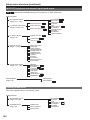
Panasonic Broadcast
AG-HVX200A
Menu Information
Using the setup menus
Use the setup menus to change the settings to
suit the scenes you are shooting or what you are
recording.
3 Press the
(or
items.
Example:
) button to display the
SET
Operation buttons
MENU button
MENU
4 Use the
and
buttons to move to the
option that you want to set.
Example:
Using the menus
• If the thumbnail menu is displayed, press
the AUDIO/THUMBNAIL button to release the
display. (Page 67)
• The menu items indicated in the blue
characters cannot be used.
1 When the unit is in other than playback or
recording mode, press the MENU button.
The following is displayed on the viewfinder and
LCD screen.
CAMERA mode (Example)
5 Press the
button to make the setting.
To change a number, use the
and
buttons
to change the setting value.
Example:
MCR/VCR mode (Example)
Menu
(Continued on the next page)
2 Press
, to highlight the function you
want to change.
97
Using the setup menus (continued)
6 To change other settings, repeat steps 4 and
5.
When you finish, press the MENU button to
return to the function screen.
7 To change other functions, repeat steps 2 to
5.
When you exit the menu mode, press the
MENU button again to return to the normal
screen.
Initializing the menu settings
The menu settings contain both the user file
settings and the scene file settings. You can
initialize them separately.
To initialize the user file (i.e. all the settings
other than the scene file settings)
Select INITIAL in USER FILE of the OTHER
FUNCTIONS screen. The current menu settings of
user file will return to the factory settings.
To initialize the scene file
From the 6 scene files, select the one you want
to initialize with the scene dial. Then in the
SCENE FILE screen, SAVE/INIT, select INITIAL.
The settings for only the selected scene file are
returned to the factory settings.
• This does not effect the other scene files.
98
Setup menu structure
Camera mode menu
P2
TAPE
indicates the available setting in P2 mode only or TAPE mode only.
CAMERA MENU
SCENE FILE
OPERATION TYPE
FRAME RATE P2
SYNCRO SCAN
DETAIL LEVEL
V DETAIL LEVEL
DETAIL CORING
CHROMA LEVEL
CHROMA PHASE
COLOR TEMP
MASTER PED
A.IRIS LEVEL
NEWS GAMMA
GAMMA
KNEE
MATRIX
SKIN TONE DTL
V DETAIL FREQ
NAME EDIT
SAVE/INIT
CAMERA SETUP
(Page 103)
SW MODE
(Pages 104 and 105)
AUTO SW
(Page 106)
ASPECT CONV
SETUP(P2) P2
SETUP(TAPE) TAPE
MID GAIN
HIGH GAIN
ATW
HANDLE ZOOM
IRIS DIAL
USER1
USER2
USER3
A.IRIS
AGC
ATW
AF
REC FORMAT(P2) P2
REC FORMAT(TAPE) TAPE
480i REC MODE P2
REC FUNCTION P2
ONE SHOT TIME P2
INTERVAL TIME P2
PREREC MODE P2
REC SPEED TAPE
AUDIO REC TAPE
MIC ALC
MIC GAIN 1
MIC GAIN 2
25M REC CH SEL P2
TC MODE
TCG
FIRST REC TC TAPE
TC PRESET
UB MODE
UB PRESET
RECORDING SETUP
(Pages 107 - 109)
AV IN/OUT SETUP
CMPNT OUT SEL P2
(Page 112)
HP MODE
DISPLAY SETUP
(Pages 113 and 114)
CARD FUNCTIONS
(Page 115)
OTHER FUNCTIONS
(Pages 115 - 118)
OPTION MENU
(Page 119)
ZEBRA DETECT 1
ZEBRA DETECT 2
MARKER
SAFETY ZONE
VIDEO OUT OSD
DATE/TIME
LEVEL METER
ZOOM FOCUS
CARD/TAPE BATT
OTHER DISPLAY
LCD BACKLIGHT
LCD SET
EVF SET
SELF SHOOT
EVF MODE
DISPLAY ASPECT
EVF COLOR
SCENE FILE P2
USER FILE P2
SD CARD FORMAT P2
REMOTE
1394 CONTROL
1394 CMD SEL
END SEARCH TAPE
PC MODE P2
REC LAMP
ACCESS LED P2
BEEP SOUND
CLOCK SET
TIME ZONE
POWER SAVE
USER FILE
HOUR METER TAPE
OPERATION P2
Menu
(Pages 101 - 103)
1394 STATUS
1394 CONFIG P2
99
Setup menu structure (continued)
MCR/VCR (playback and external input) mode menu
P2
TAPE
indicates the available setting in P2 mode only or TAPE mode only.
MCR/VCR MENU
RECORDING SETUP
(Pages 107 - 109)
32K(12bit) AUDIO TAPE
PLAYBACK FUNCTIONS
AUDIO OUT (P2) P2
(Pages 110 and 111)
AUDIO OUT (TAPE) TAPE
AV IN/OUT SETUP
CMPNT OUT SEL
(Page 112)
REC SPEED TAPE
AUDIO REC TAPE
1394 TC REGEN
TC MODE
TCG
FIRST REC TC TAPE
TC PRESET
1394 UB REGEN
UB MODE
UB PRESET
1394 IN PRESET
P2
A.DUB INPUT TAPE
1394 OUT TAPE
DISPLAY SETUP
(Pages 113 and 114)
OTHER FUNCTIONS
(Pages 115 - 118)
VIDEO OUT OSD
DATE/TIME
LEVEL METER
CARD/TAPE BATT
OTHER DISPLAY
CAMERA DATA
LCD BACKLIGHT
LCD SET
EVF SET
EVF MODE
DISPLAY ASPECT
EVF COLOR
REMOTE
END SEARCH TAPE
PC MODE P2
ACCESS LED P2
CLOCK SET
TIME ZONE
USER FILE
HOUR METER TAPE
OPERATION P2
1394 STATUS
1394 CONFIG
OPTION MENU
(Page 119)
P2
Dubbing mode menu
This screen appears only in the dubbing mode.
DUBBING MENU
RECORDING SETUP
(Pages 107-109)
DUBBING SETUP
(Page 112)
100
FORMAT SEL
PULLDOWN SEL
SETUP(TAPE)
REC SPEED TAPE
TC MODE
TCG
FIRST REC TC TAPE
TC PRESET
UB MODE
UB PRESET
Setup menu list
SCENE FILE screen
OPERATION TYPE
P2
TAPE
FRAME RATE
P2
SYNCRO SCAN
P2
TAPE
DETAIL LEVEL
P2
TAPE
V DETAIL LEVEL
P2
TAPE
DETAIL CORING
P2
TAPE
CHROMA LEVEL
P2
TAPE
CHROMA PHASE
P2
TAPE
COLOR TEMP
P2
TAPE
MASTER PED
P2
TAPE
A. IRIS LEVEL
P2
TAPE
NEWS GAMMA
P2
TAPE
Display
mode
Description of settings
(Camera) Switches the shutter and frame rate operation to the video type or film type.
VIDEO CAM: SYNCRO SCAN is displayed using 1/n units.
FILM CAM: SYNCRO SCAN is displayed as an angle.
(Camera) Selects the shooting interval and exposure time when 720P and FILM CAM is
selected. The DEFAULT value is dependent on the frame rate of the recording
format.
DEFAULT, 12, 18, 20, 22, 24, 26, 30, 32, 36, 48, 60 FRAME
(Camera) Adjusts the synchro scan shutter speed used for shooting images on a TV
screen, etc.
or
to speed up the value changing.
Press and hold the operation button to
When VIDEO CAM is selected as the OPERATION TYPE option setting:
• 60P/60i:
1/60.0 ... 1/249.8
• 30P/30PN:
1/30.0 ... 1/48.0 ... 1/249.8
• 24P/24PA/24PN:
1/24.0 ... 1/48.0 ... 1/249.8
When FILM CAM is selected as the OPERATION TYPE option setting:
The shutter speed is displayed as an angle such as “180.0d.”
10.0 deg ... 180.0 deg ... 350.0 deg (the angle can be changed in increments
of 0.5 degrees)
(Camera) Adjusts the level of the image outline correction (in the horizontal and vertical
directions).
-7...0...+7
(Camera) Adjusts the level of outline correction in the vertical direction.
-7...0...+7
(Camera) Adjusts the level of noise reduction of the detail signal.
-2...0...+7
Set to – for a clearer image. Noise increases slightly.
Set to + to reduce noise.
(Camera) Adjusts the chroma level.
-7...0...+7
(Camera) Makes fine adjustments to the chroma phase.
-7...0...+7
(Camera) Makes fine adjustments to the color temperature (after white balance
adjustment).
-7...0...+7
(Camera) Adjusts the master pedestal (black level of the image) as the basis for images.
-15...0...+15
Menu
Item
(Camera) Sets the desired AUTO IRIS level.
-4...0...+4
(Camera) Selects the news gamma curve.
ON OFF
indicates the factory setting.
101
Setup menu list (continued)
SCENE FILE screen (continued)
Item
GAMMA
P2
TAPE
KNEE
P2
TAPE
MATRIX
P2
TAPE
Display
mode
Description of settings
(Camera) Selects the gamma curves other than the news gamma curve.
HD NORM:
This gamma setting is suitable for HD shooting.
LOW:
Makes a mellow image using the gamma curve which has a gentle incline in
low-brightness curve. The contrast sharpens.
SD NORM:
This is the normal video setting, carried over from the DVX100 series.
HIGH:
Expands the tone of dark parts and makes a brighter image using the gamma
curve which has a sharp incline in low-brightness curve. The contrast softens.
B.PRESS:
Makes the contrast shaper than LOW.
CINE-LIKE_D:
Makes a cinema-like image.
CINE-LIKE_V:
Makes a cinema-like image with emphasized contrast.
When you select CINE-LIKE gamma, we recommend to set the lens aperture
lower than normal image level (approximately 1/2) to enjoy the full benefit of the
function.
(Camera) To avoid overexposure, select the compression level (knee point) of the high
intensity video signals received through CCD.
AUTO:
Sets the level automatically according to the received signals.
LOW:
Low setting (Compression starts at approx. 80%.)
MID:
Medium setting (Compression starts at approx. 90%.)
HIGH:
High Setting (Compression starts at approx. 100%.)
(Camera) Selects the MATRIX table suitable for the desired color expression during
shooting.
NORM:
Suitable for shooting in the open air or under a halogen lamp.
ENRICHED:
Suitable for brighter colors than the NORM mode.
FLUO:
Suitable for shooting under fluorescent light indoors.
CINE-LIKE:
Suitable for cinema-like image.
indicates the factory setting.
102
SCENE FILE screen (continued)
Item
SKIN TONE DTL
P2
TAPE
V DETAIL FREQ
P2
TAPE
NAME EDIT
P2
TAPE
SAVE/INIT
P2
TAPE
Display
mode
Description of settings
(Camera) Sets the skin tone details. Select ON to reduce the skin tone details and soften
the skin tone.
ON OFF
(Camera) Sets the vertical detail for shooting in 480i progressive mode.
THIN: Makes the detail thin.
MID: Makes the detail slightly thicker.
THICK: Makes the detail thicker.
When images were shot in the progressive mode in which the vertical detail is
set as “THIN” or “MID” and are played on a monitoring television (60i interlace),
you will see flickers caused on horizontal lines and almost horizontal oblique
lines. When playing back images in the progressive mode or when editing
images or performing other postprocessing, images with a higher resolution will
be obtained with the THIN or MID setting than with the THICK setting.
(Camera) Edits the name of the selected scene file you have selected with the scene file
dial.
(Camera) SAVE:
Saves the changed scene file settings.
• The settings will not be saved if you exit the menu mode, switch to the MCR/
VCR mode or turn the camera off without selecting SAVE.
INITIAL:
The settings of the scene file selected with the scene file dial are returned to
the factory settings.
CAMERA SETUP screen
ASPECT CONV
P2
TAPE
SETUP (P2)
P2
SETUP (TAPE)
TAPE
Display
mode
Description of settings
(Camera) Selects the aspect ratio of the image you record in 480i format. This item cannot
be selected when the 1080i or 720P recording format is used. (Page 44)
NORMAL
LETTER BOX
SQUEEZE
(Camera) Switch the setup level of video signals in 480i format using a P2 card.
0%:
Setup is switched to 0% for both the camera output and the recording.
7.5%A:
Setup is switched to 7.5% for the camera output and 0% for the recording.
(Camera) Switch the setup level of video signals in 480i format using a tape.
0%:
Setup is switched to 0% for both the camera output and the recording.
7.5%:
Setup is switched to 7.5% for both the camera output and the recording.
Menu
Item
indicates the factory setting.
103
Setup menu list (continued)
SW MODE screen
Item
MID GAIN
P2
TAPE
HIGH GAIN
P2
TAPE
ATW
P2
TAPE
HANDLE ZOOM
P2
TAPE
IRIS DIAL
P2
TAPE
Display
mode
Description of settings
(Camera) Sets the gain value assigned to the M position of the GAIN switch.
0dB, 3dB, 6dB, 9dB, 12dB
(Camera) Sets the gain value assigned to the H position of the GAIN switch.
0dB, 3dB, 6dB, 9dB, 12dB
(Camera) Sets the operation of the ATW (Auto Tracking White Balance) function assigned
to the WHITE BAL switch. When the ATW function is set to the AUTO/MANUAL
switch or USER button, the operation remains effective.
Ach:
Activates the ATW function when the WHITE BAL switch is set to A.
Bch:
Activates the ATW function when the WHITE BAL switch is set to B.
PRST:
Activates the ATW function when the WHITE BAL switch is set to PRST.
OFF:
Deactivates the ATW function.
(Camera) Sets the zoom speed assigned to each setting position of the HANDLE ZOOM
switch.
L/OFF/H:
Sets LOW (low speed)/OFF/HIGH (high speed) to the 1/2/3 position. (Zoom is
disabled when set to OFF.)
L/M/H:
Sets LOW (low speed)/MID (medium speed)/HIGH (high speed) to the 1/2/3
position.
L/OFF/M:
Sets LOW (low speed)/OFF/MID (medium speed) to the 1/2/3 position. (Zoom
is disabled when set to OFF.)
(Camera) Sets the rotation direction and the aperture control of the IRIS dial. (In MANUAL
IRIS mode)
DOWN OPEN:
The iris opens when the IRIS dial is turned downward.
UP OPEN:
The iris opens when the IRIS dial is turned upward.
indicates the factory setting.
104
SW MODE screen (continued)
USER1
P2
TAPE
USER2
P2
TAPE
USER3
P2
TAPE
Display
mode
Description of settings
(Camera) Selects the function assigned to the USER1 button.
REC CHECK:
Performs Rec Check.
SPOTLIGHT:
Auto iris control for the spotlight ON/OFF
BACKLIGHT:
Auto iris control for the backlight compensation (Page 45)
BLACKFADE:
Blackfade (Page 45)
WHITEFADE:
Whitefade (Page 45)
ATW:
ATW function ON/OFF
ATWLOCK:
Fixes the white balance value when the button is pressed during ATW. Press
again to perform ATW.
GAIN: 18 dB:
Press the button to set the gain value to 18 dB. This setting takes effect with
the 60i and 60P recording formats only. It is not valid when the recording
frame rate is less than 22 fps or when the slow shutter mode (1/15) is
established.
• When the gain value is set to 18 dB or set from 18 dB to another value, the
image can be disordered for a moment.
• If the unit is being used in the MANUAL mode or AUTO mode, set the
AGC item on the AUTO SW screen of the setting menu to OFF to use this
function.
FOCUS RING:
Selects the focus ring function (FOCUS or IRIS). The FOCUS RING is
functional when the FOCUS switch is in AUTO mode.
INDEX/MEMO:
Text memo recording (P2 card)(Page 47)/Index recording (cassette tape)
(Page 48)
SLOT SEL (P2 card only):
Selects one of the P2 card slots. (Page 47)
SHOT MARK (P2 card only):
Shot mark recording (Page 47)
(Camera) Selects the function assigned to the USER2 button.
The settings are the same as USER1 above.
BACKLIGHT
(Camera) Selects the function assigned to the USER3 button.
The settings are the same as USER1 above.
INDEX/MEMO
Menu
Item
indicates the factory setting.
105
Setup menu list (continued)
AUTO SW screen
Item
A.IRIS
P2
TAPE
AGC
P2
TAPE
ATW
P2
TAPE
AF
P2
TAPE
Display
mode
Description of settings
(Camera) ON:
Performs the auto iris control in auto mode. The IRIS button is deactivated.
OFF:
Deactivates the auto iris control in auto mode. This performs the iris control
selected with the IRIS button.
(Camera) Sets the Auto Gain Control when the ON is selected in A.IRIS.
6dB:
Performs the Auto Gain Control (max. 6 dB) in auto mode.
12dB:
Performs the Auto Gain Control (max. 12 dB) in auto mode.
OFF:
Does not perform the Auto Gain Control in auto mode. Initiates the control of
the gain selected by the GAIN switch.
(Camera) ON:
Performs the ATW (Auto Tracing White Balance) function in auto mode. You
cannot select ON/OFF of the ATW function with the WHITE BAL switch or the
USER button when this is selected. However, if ATWLOCK is assigned to the
USER button, you can set the white balance value with the USER button.
OFF:
Does not perform the white balance function in auto mode. This performs the
white balance function selected with the WHITE BAL switch.
(Camera) ON:
Performs auto focusing in auto mode. You cannot use the FOCUS switch and
PUSH AUTO button when this is selected.
OFF:
Does not perform auto focusing in auto mode.This performs the focusing
selected with the FOCUS switch or PUSH AUTO button.
indicates the factory setting.
106
RECORDING SETUP screen
Item
REC FORMAT (P2)
P2
REC FORMAT
(TAPE)
Display
mode
Description of settings
(Camera) Selects the recording format for P2 card.
1080i/60i, 1080i/30P, 1080i/24P, 1080i/24PA, 720P/60P, 720P/30P, 720P/24P,
720P/30PN, 720P/24PN, 480i/60i, 480i/30P, 480i/24P, 480i/24PA
(Camera) Selects the recording format for cassette tape.
480i/60i, 480i/30P, 480i/24P, 480i/24PA
TAPE
P2
REC FUNCTION
P2
ONE-SHOT TIME
P2
INTERVAL TIME
P2
PREREC MODE
P2
REC SPEED
TAPE
AUDIO REC
TAPE
MIC ALC
P2
TAPE
MIC GAIN 1
P2
TAPE
MIC GAIN 2
P2
TAPE
25M REC CH SEL
P2
(Camera) Select the recording mode for a 480i recording format.
DVCPRO50, DVCPRO, DV
(Camera) Selects the special recording mode. (Pages 48 - 50)
NORMAL, INTERVAL, ONE SHOT, LOOP
(Camera) Selects the one-shot recording time. (Page 50)
1F, 2F, 4F, 8F, 16F, 1s
(Camera) Selects the interval time for interval recording. (Page 49)
2F, 4F, 8F, 16F, 1s, 2s, 5s, 10s, 30s, 1m, 5m, 10m
(Camera) Sets PRE RECORDING to ON or OFF. (Page 48)
ON OFF
(Camera) Selects the recording time mode.
(VCR)
SP: SP (standard) mode
(DUB)
LP: LP (long play) mode
(Camera) Selects the audio recording mode for conversion to PCM audio.
(VCR)
32K(12bit): 12bit/32kHz
48K(16bit): 16bit/48kHz
(Camera) Sets mic level auto control to ON or OFF. (Page 54)
ON OFF
Set to ON to reduce distortion at high input levels.
This setting does not change the audio signal recording level. Use the AUDIO
control knob to adjust the audio signal recording level.
(Camera) Sets the input level of the external microphone connected to the INPUT 1
terminal. (Page 53)
-50dB -60dB
(Camera) Sets the input level of the external microphone connected to the INPUT 2
terminal. (Page 53)
-50dB -60dB
(Camera) Selects the recording audio channel for DVCPRO25 and DV formats. (Page 53)
2CH, 4CH
<Notes>
• Even when 4CH is selected as this item’s setting, the signals will be
input to two channels (always CH1 and CH2) when there are two 1394
input channels.
• Similarly, even when 4CH is selected, the 1394 output signals will be
delivered to two channels (always CH1 and CH2).
Menu
480i REC MODE
indicates the factory setting.
107
Setup menu list (continued)
RECORDING SETUP screen (continued)
Item
1394 TC REGEN
P2
TAPE
TC MODE
P2
TAPE
TCG
P2
TAPE
FIRST REC TC
TAPE
TC PRESET
P2
TAPE
Display
mode
Description of settings
(MCR/
VCR)
Selects the time code used for recording the signal from equipment connected
to the 1394 terminal.
ON:
Records using the time code of the signal input through the 1394 terminal.
OFF:
Records using the time code set in TC MODE/TCG/FIRST REC TC.
• If you select ON here, this has priority over the settings in TC MODE/TCG/
FIRST REC TC.
• If there is no input to the 1394 terminal, the camera follows the settings in TC
MODE/TCG/FIRST REC TC.
(Camera)
(MCR/
VCR)
(DUB)
Selects the correction mode of the internal time code generator.
DF: Uses the drop frame mode.
NDF: Uses the non-drop frame mode.
• The non-drop frame mode will be used when you set recording frame rate of
recording format to 24P, 24PA or 24PN.
(Camera) Sets the mode in which you advance the time code.
(MCR/
FREE RUN:
VCR)
The time code is advanced regardless of the operation mode.
(DUB)
Records in the dubbing mode in such a way that the time codes of the clips
on the P2 card are carried over. User information is also carried over.
• When setting a frame rate other than 24P during operation with the
720P/24PN format or other than 30P during operation with the 720P/30PN
format, the FREE RUN operation for the time code will not be performed, and
the REC RUN operation will be performed instead.
REC RUN:
The time code is advanced only when recording.
(Camera) Selects the time code to be recorded when you start recording.
(VCR)
REGEN:
(DUB)
Regenerates the time code on the tape to continue recording.
PRESET:
The time code on the tape is not regenerated. The value you set in TC
PRESET is used as the initial value to record the time code. However, if you
perform subsequent shooting, the time code will always be regenerated.
(Camera) Sets the initial time code. This is activated when you select PRESET in FIRST
(MCR/
REC TC.
VCR)
• Set the frame value to 0 or a multiple of 5 when you set recording frame rate
(DUB)
of recording format to 24P, 24PA or 24PN. If any other value, the recorded
time code will mis-match.
indicates the factory setting.
108
RECORDING SETUP screen (continued)
Item
1394 UB REGEN
P2
TAPE
UB MODE
P2
TAPE
Display
mode
Description of settings
(MCR/
VCR)
Selects the user information used when recording the signals from equipment
connected to the 1394 terminal.
ON:
Records using the user information of the signal input through the 1394
terminal.
OFF:
Records using the user information set in UB MODE.
• If you select ON here, this has priority over the setting in UB MODE.
• The user information is recorded only when the signal contains the user
information.
• If there is no input to the 1394 terminal, the camera follows the UB MODE
settings.
(Camera)
(MCR/
VCR)
(DUB)
Set the content for user information.
USER: Records the information of user.
TIME: Records the time at recording.
DATE: Records the date at recording.
TCG: Records the values of the time code generator.
FRM. RATE: Records the frame rate information for frame conversion.
a
b
c
d
a:Checking information for user information
b:Frame sequence No.
• 0 to 4 are displayed in the 24P/24P (ADV) mode.
• F is displayed in the 60i/30P mode.
c:Frame rates
• Frame rate (60/30/24)
• I/P ID
• Conversion data
• Frame rate coefficient
d:Recording management data
• Frame update information
• REC START/STOP information
<Note>
To play back a clip recorded with native recording
To change 1394 output user information to frame rate information, change this
setting to FRM.RATE and play back the clip. The user information displayed on
the screen at this time is changed to frame rate information.
P2
TAPE
1394 IN PRESET
P2
TAPE
(Camera) Sets the user information. Select USER in UB MODE.
(MCR/
VCR)
(DUB)
(MCR/
VCR)
Menu
UB PRESET
Synchronizes the internal TCG value with the TC of 1394 input when you press
the TC SET button.
ON: The synchronization mode is on.
OFF: The synchronization mode is off.
indicates the factory setting.
109
Setup menu list (continued)
PLAYBACK FUNCTIONS screen
Item
32K(12bit) AUDIO
Display
mode
Sets the audio to output as CH1 and CH2 signals when playing back a tape
recorded in the 32K (12bit) audio mode.
ST1:
Selects the sound that was recorded during shooting.
CH1 signals = CH1 track
CH2 signals = CH2 track
ST2:
Selects the sound that was dubbed on the recording.
CH1 signals = CH3 track
CH2 signals = CH4 track
MIX:
Mixes the sound that was recorded in shooting and audio dubbing.
CH1 signals = CH1 track + CH3 track
CH2 signals = CH2 track + CH4 track
<Note>
When the sound is recorded in the 48K (16bit) audio mode, CH3 and CH4 do
not exist so the following is always the case.
CH1 signals = CH1 track
CH2 signals = CH2 track
(MCR/
VCR)
Sets the audio signals to output from the AUDIO IN/OUT pin jack when the P2
card or the tape is played back.
CH1 · CH2:
CH1 output = CH1 signals, CH2 output = CH2 signals
CH1:
CH1 output = CH1 signals, CH2 output = CH1 signals
CH2:
CH1 output = CH2 signals, CH2 output = CH2 signals
CH3 · CH4: (P2 card only)
CH1 output = CH3 signals, CH2 output = CH4 signals
CH3: (P2 card only)
CH1 output = CH3 signals, CH2 output = CH3 signals
CH4: (P2 card only)
CH1 output = CH4 signals, CH2 output = CH4 signals
TAPE
AUDIO OUT (P2)
P2
AUDIO OUT (TAPE)
TAPE
Description of settings
(VCR)
indicates the factory setting.
110
PLAYBACK FUNCTIONS screen (continued)
32K(12bit) AUDIO item/AUDIO OUT item settings and audio track signals output from the AUDIO IN/OUT
jack TAPE
32K(12bit) AUDIO
setting
ST1
32K (12bit)
ST2
MIX
48K (16bit)
—
AUDIO OUT setting
CH1 · CH2
CH1
CH2
CH1 · CH2
CH1
CH2
—
CH1 · CH2
CH1
CH2
AUDIO IN/OUT jack
CH1 output
CH1
CH1
CH2
CH3
CH3
CH4
CH1+CH3
CH1
CH1
CH2
AUDIO IN/OUT jack
CH2 output
CH2
CH1
CH2
CH4
CH3
CH4
CH2+CH4
CH2
CH1
CH2
Menu
Audio recording
mode
111
Setup menu list (continued)
DUBBING SETUP screen
Item
Display
mode
Description of settings
FORMAT SEL
(DUB)
Selects the format of the clips to be played back during dubbing.
1080i/60i, 1080i/30P, 1080i/24P, 1080i/24PA, 720P/60P, 720P/30P, 720P/24P,
720P/30PN, 720P/24PN
PULLDOWN SEL
(DUB)
Selects the pulldown method for 24PN (native format).
24P:
The 24 fps images are converted into 60-field interlace signals by the 2:3
conversion system.
24PA:
The 24 fps images are converted into 60-field interlace signals by the 2:3:3:2
advanced conversion system.
SETUP
(DUB)
Switch the setup level of video signals in 480i format for dubbing.
0%:
Setup is switched to 0% for both the camera output and the recording.
7.5%:
Setup is switched to 7.5% for both the camera output and the recording.
AV IN/OUT SETUP screen
Item
CMPNT OUT SEL
P2
HP MODE
P2
TAPE
A. DUB INPUT
Display
mode
(Camera) Selects the type of component terminal.
(MCR)
720P: Monitor which supports the D4 terminal
1080i: Monitor which supports the D3 terminal
480i: Monitor which supports the D1 terminal
The signals recorded in the 720P format are cross-converted only when 1080i
format signals are to be output. In all other cases, they are output without being
converted.
(Camera) Selects the sound heard through the headphones.
LIVE:
The sound which has been input from the microphone is output as is. This
setting is selected when delays in the sound are annoying.
RECORDING:
The sound in the status which is to be recorded (the sound synchronized with
the images) is output.
(VCR)
Selects the audio to be recorded for audio dubbing. (Page 81)
MIC:
This sets the input from the internal microphone, INPUT1 and INPUT2
connectors.
A_IN:
This sets the input from the AUDIO IN/OUT connector.
(VCR)
Select ON to convert analog input signals into digital signals and output them
from the 1394 terminal.
ON OFF
TAPE
1394 OUT
TAPE
Description of settings
indicates the factory setting.
112
DISPLAY SETUP screen
ZEBRA DETECT 1
P2
TAPE
ZEBRA DETECT 2
P2
TAPE
MARKER
P2
TAPE
SAFETY ZONE
P2
TAPE
VIDEO OUT OSD
P2
TAPE
DATE/TIME
P2
TAPE
LEVEL METER
P2
TAPE
Display
mode
Description of settings
(Camera) Selects the brightness level of the left-leaning zebra patterns on the screen.
50%, 55%, 60%, 65%, 70%, 75%, 80%, 85%, 90%, 95%, 100%, 105%
(Camera) Selects the brightness level of the right-leaning zebra patterns on the screen.
50%, 55%, 60%, 65%, 70%, 75%, 80%, 85%, 90%, 95%, 100%, 105%, OFF
<Note>
• The zebra patterns do not appear if you select OFF.
(Camera) Select ON to display the marker. (Page 43)
ON OFF
• To display the marker, press the ZEBRA button.
(Camera) Sets SAFETY ZONE to ON or OFF.
OFF , 90%, 4:3
(Camera) Select ON to output the information displayed on the screen together with the
(MCR/
signals from the VIDEO IN/OUT jack.
VCR)
ON OFF
<Notes>
• When a tape is used for recording, no on-screen displays (OSD) will be output
while recording is underway even when this function has been set to ON.
However, OSD will be output to the 1394 output during recording standby. If
OSD is not required, set the function to OFF.
• If this option is set to ON when performing backup recording while a tape is
used, the OSD will be output to the 1394 output at all times except when the
unit is in the recording mode.
Bear in mind that the OSD may be recorded inadvertently if backup recording
is performed when a setting other than OFF is selected for the 1394
CONTROL option (page 115) on the OTHER FUNCTIONS screen.
(Camera) Sets whether to display the date and time on the screen and whether to output
(MCR/
from the VIDEO IN/OUT jack.
VCR)
OFF:
The date and time are not displayed.
TIME:
The time is displayed.
DATE:
The date is displayed.
TIME&DATE:
The time and date are displayed.
• If you select any setting other than OFF, the date and/or time are included
in the output signals regardless of the VIDEO OUT OSD setting. (The OFF
setting can be selected also using the remote control. (Page 76))
(Camera) Select ON to display the audio level meter.
(MCR/
ON OFF
VCR)
Menu
Item
indicates the factory setting.
113
Setup menu list (continued)
DISPLAY SETUP screen (continued)
Item
ZOOM · FOCUS
P2
TAPE
CARD/TAPE · BATT
P2
TAPE
OTHER DISPLAY
P2
TAPE
CAMERA DATA
P2
TAPE
LCD BACKLIGHT
P2
TAPE
LCD SET
P2
TAPE
EVF SET
P2
TAPE
SELF SHOOT
P2
TAPE
EVF MODE
P2
TAPE
DISPLAY ASPECT
P2
TAPE
EVF COLOR
P2
TAPE
Display
mode
Description of settings
(Camera) Selects the unit of zoom and focus values.
OFF, NUMBER, mm/feet, mm/m
<Note>
Use the mm/feet or mm/m display only as a general guideline since it is not
entirely accurate.
(Camera) Select ON to display the remaining card/tape and battery charge.
(MCR/
ON OFF
VCR)
(Camera) Select how much information to display on the screen. (Page 96)
(MCR/
OFF, PARTIAL, ALL
VCR)
(MCR/
VCR)
Select ON to display the camera settings (such as image stabilizer, F-number,
and gain value) during tape playback.
ON OFF
<Note>
In the P2 mode, this item appears only when 480i REC MODE has been set to
DV. (Page 107)
(Camera) Adjusts the backlight of the LCD monitor. Select HIGH for brighter backlight.
(MCR/
HIGH NORMAL
VCR)
(Camera) Adjusts the display level of the images on the LCD monitor. (Page 23)
(MCR/
LCD COLOR LEVEL
VCR)
LCD BRIGHTNESS
LCD CONTRAST
(Camera) Adjusts the display level of the images on the viewfinder. (Page 23)
(MCR/
EVF COLOR LEVEL
VCR)
EVF BRIGHTNESS
EVF CONTRAST
(Camera) Selects the LCD mirror mode for self-portrait shooting. Select MIRROR to
reverse left and right at self-portrait shooting. (Page 42)
NORMAL
MIRROR
(Camera) Selects the LCD monitor and the viewfinder display setting.
(MCR/
ON:
VCR)
Images always appear on the viewfinder.
AUTO:
Images do not appear on the viewfinder when the LCD is open.
(Camera) Selects the aspect ratio of the LCD monitor and the viewfinder.
(MCR/
AUTO: Changes automatically to the appropriate ratio according to the
VCR)
recording or play mode information.
4:3 : Fixed at 4:3.
<Note>
Black bands appear at the top and bottom of the screen when images are
displayed at a 16:9 aspect ratio. No parts of the images are missing.
(Camera) Selects color or black and white images on the viewfinder.
(MCR/
ON: Color
VCR)
OFF: Black and white
indicates the factory setting.
114
CARD FUNCTIONS screen
Item
SCENE FILE
P2
USER FILE
P2
SD CARD FORMAT
Display
mode
Description of settings
(Camera) You can save four SCENE FILE settings to the SD memory card, and can also
title the saved files.
READ: Read
WRITE: Write
(Camera) You can save four file settings (excluding SCENE FILE) to the SD memory
card, and can also title the saved file.
READ: Read
WRITE: Write
(Camera) Formats the SD memory cards.
P2
OTHER FUNCTIONS screen
REMOTE
P2
TAPE
1394 CONTROL
P2
TAPE
1394 CMD SEL
P2
TAPE
Display
mode
Description of settings
(Camera) Sets the operations of the supplied remote control unit. (Remote control setup
(MCR/
(Page 19))
VCR)
VCR1:
Accepts commands from the remote control set for VCR1.
VCR2:
Accepts commands from the remote control set for VCR2.
OFF:
Operations are not accepted from any remote control.
(Camera) Sets the control method for backup recording using a backup unit connected to
the 1394 terminal.
OFF:
The backup unit is not controlled.
EXT:
The backup unit can be controlled by the START/STOP button. The images
shot by the camera recorder are recorded by the backup unit. Note that the
camera recorder does not record them.
BOTH:
The images shot by the camera recorder are recorded by both the camera
recorder and backup unit.
CHAIN:
When the camera recorder’s media approaches its end during shooting, the
backup unit in the recording stand-by mode automatically starts recording
images.
(Camera) Sets how the START/STOP button works for the backup unit.
REC_P:
This switches between recording and pause.
STOP:
This switches between recording and stop.
<Note>
If the backup unit does not have a rec pause function, select STOP.
Menu
Item
indicates the factory setting.
115
Setup menu list (continued)
OTHER FUNCTIONS screen (continued)
Item
END SEARCH
TAPE
PC MODE
P2
REC LAMP
P2
TAPE
ACCESS LED
P2
BEEP SOUND
P2
TAPE
CLOCK SET
P2
TAPE
Display
mode
Description of settings
(Camera) Sets the operation when the END SEARCH button is pressed.
(VCR)
BLANK: Searches for the unrecorded parts on the tape.
REC END: Searches for the last segment shot.
(Camera) Selects the terminal for data transfer. (You cannot select USB and 1394 at the
(MCR)
same time.)
USB DEVICE:
Mode for sending files using the USB connector.
1394 DEVICE:
Mode for sending files using the 1394 connector.
1394 HOST:
Mode for copying files from the P2 card onto an external hard disk drive using
the 1394 connector.
(Camera) Sets lighting of the tally lamp.
OFF:
The tally lamp does not light.
FRONT:
Front tally lamp (microphone side) lights.
REAR:
Rear tally lamp (viewfinder side) lights.
BOTH:
Both tally lamps light.
(Camera) Sets the access lamp to ON or OFF.
(MCR)
ON:
The lamp lights up and blinks as per the regular specifications.
OFF:
The lamp is OFF in all circumstances.
(Camera) Turns the beep sound ON or OFF.
ON OFF
When ON is selected, the beep is sounded under the circumstances set forth
below.
When the beep is sounded, the audio signals from the output connector are
muted before the beep sound is output.
• When the memory of the P2 card or the tape has been used up during
recording
• When a recordable tape has not been loaded when the power is turned on
• When a recording-inhibited tape has been inserted
• When condensation has formed inside the camera-recorder
• When trouble has occurred in the camera-recorder
<Note>
When LIVE has been set for the HP MODE option on the AV IN/OUT SETUP
screen, no beeping sounds will be emitted even if ON is set for the BEEP
SOUND option.
(Camera) Sets the camera-recorder’s calendar.
(MCR/
VCR)
indicates the factory setting.
116
OTHER FUNCTIONS screen (continued)
TIME ZONE
P2
TAPE
Display
mode
Description of settings
(Camera) Adds to or deducts from GMT the time value of -12:00 to +13:00 in 30-minute
(MCR/
steps. (As an exception, you can set +12:45.) Refer to the table below.
VCR)
0:00
Time
difference
00:00
Area
Time
difference
Area
Greenwich
– 00:30
– 01:00
Azores Islands
– 01:30
– 02:00
Mid-Atlantic
– 02:30
– 03:00
Buenos Aires
– 03:30
– 04:00
Halifax
– 04:30
– 05:00
New York
– 05:30
– 06:00
Chicago
– 06:30
– 07:00
Denver
– 07:30
– 08:00
Los Angeles
– 08:30
– 09:00
Alaska
– 09:30
– 10:00
Hawaii
– 10:30
– 11:00
Midway Island
– 11:30
– 12:00
Kwajalein
+ 11:30
Norfolk Island
+ 10:30
Lord Howe Island
Darwin
+ 13:00
Newfoundland Island
Marquesas Islands
+ 12:00
New Zealand
+ 09:30
+ 11:00
Solomon Islands
+ 08:30
+ 10:00
Guam
+ 07:30
+ 09:00
Tokyo
+ 06:30
Rangoon
+ 08:00
Beijing
+ 05:30
Bombay
+ 07:00
Bangkok
+ 04:30
Kabul
+ 06:00
Dacca
+ 03:30
Tehran
+ 05:00
Islamabad
+ 02:30
+ 04:00
Abu Dhabi
+ 01:30
+ 03:00
Moscow
+ 00:30
+ 02:00
Eastern Europe
+ 12:45
+ 01:00
Central Europe
Chatham Islands
indicates the factory setting.
Menu
Item
117
Setup menu list (continued)
OTHER FUNCTIONS screen (continued)
Item
POWER SAVE
P2
TAPE
USER FILE
P2
TAPE
HOUR METER
TAPE
OPERATION
P2
Display
mode
Description of settings
(Camera) Selects the power-saving mode when the top panel operation keys, DISP/
MODE CHK button, USER1-3 buttons and EVF DTL button have not been
operated for 5 minutes or so.
ON:
The camera-recorder’s power is set to OFF.
OFF:
The cylinder head remains stopped without turning off the camera-recorder’s
power.
• When connection is made with an external device using the IEEE1394 cable
and the communication mode is established in this way, the power will not be
set off even when none of the above buttons has been operated.
• The power will not be turned off when a P2 card or tape has not been
installed in the P2 mode or TAPE mode, respectively, even if ON has been
selected as this item’s setting.
(Camera) LOAD:
(MCR/
The previous user file settings are loaded.
VCR)
SAVE:
The changed user file settings are saved.
INITIAL:
The user file settings are returned to the factory settings.
After performing LOAD or INITIAL, turn the POWER switch OFF and then
back ON to activate the settings.
• The setting for the TIME ZONE option (page 117) remains unchanged even
when INITIAL is performed.
(Camera) Displays the total running time (a 5-digit figure per hour) of the cylinder head.
(VCR)
(Camera) Displays the power-on time (a 5-digit figure).
(MCR)
indicates the factory setting.
118
OPTION MENU
This menu is displayed when the DISP/MODE CHK button is held down, and after the details of the
shooting status are displayed, the MENU button is then pressed.
Use it to check the connection status during nonlinear editing.
1394 STATUS
P2
TAPE
1394 CONFIG
P2
Display
mode
Description of settings
(Camera) 1394 status display screen appears.
(MCR/
• When a P2 card is used
VCR)
FORMAT: Format of the signals which are input or output.
RATE:
Transfer rate of the signals which are input or output.
60/50:
System of the signals which are input or output.
CH:
Value of the channels in which the signals are input or output.
SPEED: Transfer speed of the signals which are input or output.
STATUS: Status of the signals which are input or output using the IEEE1394
digital interface.
VIDEO: Status of the video signals which are input or output.
AUDIO: Status of the audio signals which are input or output.
• When a tape is used
FORMAT: Format of the signals which are input or output.
RATE:
Transfer rate of the signals which are input or output.
60/50:
System of the signals which are input or output.
CH:
Value of the channels in which the signals are input or output.
SPEED: Transfer speed of the signals which are input or output.
MODE:
Status of the signals which are input or output using the IEEE1394
digital interface.
RX:
Reception status
TX:
Transmission status
(Camera) 1394 extended menus appear.
(MCR)
DFLT: Normally, DFLT is used.
1-255
indicates the factory setting.
Menu
Item
119