1
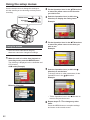
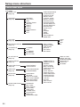
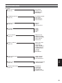
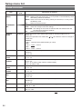
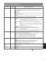
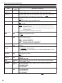
Panasonic Broadcast
AG-HMC150
Menu Information
Using the setup menus
Use the setup menus to change the settings to
suit the scenes you are shooting or what you are
recording.
MENU button
Operation
lever
MENU
EXEC
PUSH-ENTER
AUDIO MON/ADV
2 Tilt the Operation lever in the
directions
to move the yellow cursor to the function
you wish to set.
3 Push the Operation lever (or tilt in the
direction) to display the setting items.
Example:
4 Tilt the Operation lever in the
Using the menus
directions
to move the yellow cursor to the item you
wish to set.
Example:
• The menu items indicated in the gray
characters cannot be changed its settings.
1 When the unit is in other than playback or
recording mode, press the MENU button.
The following is displayed on the viewfinder and
LCD monitor.
CAM mode (Example)
5 Push the Operation lever (or tilt in the
direction) to set the item.
To change values or other parameters, tilt the
Operation lever in the
directions.
Example:
PB mode (Example)
• Tilt the Operation lever in the
return to the previous menu.
direction to
6 Repeat steps 4 - 5 to change any other
items.
Press the MENU button to complete settings
and return to the normal screen.
82
7 Repeat steps 2 - 5 to change any other
settings.
Press the MENU button to complete settings
and return to the normal screen.
Initializing the menu settings
The menu settings contain both the user file
settings and the scene file settings. You can
initialize them separately.
To initialize the user file (i.e. all the settings
other than the scene file settings)
Select INITIALIZE in LOAD/SAVE/INIT of the
USER FILE screen. The current menu settings of
user file will return to the factory settings.
To initialize the scene file
From the 6 scene files, select the one you want to
initialize with the scene dial. Then in the SCENE
FILE screen, LOAD/SAVE/INIT, select INITIALIZE.
The settings for only the selected scene file are
returned to the factory settings.
• This does not effect the other scene files.
Menu
If you wish to initialize the user file and scene
files at the same time, the user file and all six
scene files can be restored to their factory
default settings by selecting YES for the MENU
INIT item on the OTHER FUNCTIONS screen.
83
Setup menu structure
Camera mode menu
CAM MENU
SCENE FILE
(Page 86)
SW MODE
(Page 88)
MID GAIN
HIGH GAIN
ATW
HANDLE ZOOM
IRIS DIAL
USER1
USER2
USER3
FOCUS ASSIST
WFM
LCD
CARD READ/WRITE
LOAD/SAVE/INIT
SYNCRO SCAN
DETAIL LEVEL
V DETAIL LEVEL
DETAIL CORING
CHROMA LEVEL
CHROMA PHASE
COLOR TEMP Ach
COLOR TEMP Bch
MASTER PED
A.IRIS LEVEL
DRS
GAMMA
KNEE
MATRIX
SKIN TONE DTL
NAME EDIT
AUTO SW
(Page 90)
RECORDING SETUP
(Page 91)
TC/UB SETUP
(Page 92)
TC MODE
TCG
TC PRESET
UB PRESET
EXT TC LINK
REC FORMAT
PREREC MODE
TIME STAMP
MIC ALC
MIC GAIN1
MIC GAIN2
AV OUT SETUP
(Page 93)
DISPLAY SETUP
(Page 94)
84
CARD FUNCTIONS
(Page 96)
CARD FORMAT
CARD STATUS
USER FILE
(Page 96)
CARD READ/WRITE
LOAD/SAVE/INIT
META DATA
(Page 96)
CARD READ
RECORD
USER CLIP NAME
CLIP COUNT RESET
META DATA PROP
META INITIAL SET
OTHER FUNCTIONS
(Page 98)
IR REMOTE
REC LAMP
BEEP SOUND
CLOCK SET
TIME ZONE
POWER SAVE
SYSTEM INFO
MENU INIT
OPERATION TIME
ZEBRA DETECT1
ZEBRA DETECT2
MARKER
SAFETY ZONE
REC COUNTER
VIDEO OUT OSD
DATE/TIME
LEVEL METER
ZOOM & FOCUS
CARD & BATTERY
OTHER DISPLAY
LCD BACKLIGHT
LCD SET
EVF SET
SELF SHOOT
EVF COLOR
A.IRIS
AGC
ATW
AF
HDMI OUT SEL
CMPNT OUT SEL
DOWNCON MODE
VIDEO SETUP
AUDIO OUT
HP MODE
Playback mode menu
PB FORMAT
REPEAT PLAY
RESUME PLAY
SKIP MODE
THUMBNAIL SETUP
(Page 97)
THUMBNAIL MODE
INDICATOR
DATA DISPLAY
DATE FORMAT
OPERATION
(Page 98)
DELETE
INDEX
CLIP PROTECT
SW MODE
(Page 88)
USER1
USER2
USER3
LCD
AV OUT SETUP
(Page 93)
HDMI OUT SEL
CMPNT OUT SEL
DOWNCON MODE
VIDEO SETUP
AUDIO OUT
DISPLAY SETUP
(Page 94)
VIDEO OUT OSD
DATE/TIME
LEVEL METER
CARD & BATTERY
OTHER DISPLAY
LCD BACKLIGHT
LCD SET
EVF SET
EVF COLOR
CARD FUNCTIONS
(Page 96)
CARD FORMAT
CARD STATUS
CLIP PROPERTY
USER FILE
(Page 96)
CARD READ/WRITE
LOAD/SAVE/INIT
OTHER FUNCTIONS
(Page 98)
IR REMOTE
CLOCK SET
TIME ZONE
SYSTEM INFO
OPERATION TIME
Menu
PB MENU
PLAY SETUP
(Page 97)
85
Setup menu list
SCENE FILE screen
Item
CARD READ/
WRITE
Display
mode
(Camera)
Description of settings
Reads and writes scene files on the SD Memory Card.
READ: Reads scene files (all scenes, F1 to F6) saved on the SD Memory Card
after setting values are selected.
WRITE: Saves current scene file setting values (for all scenes, F1 to F6) on the
SD Memory Card.
Returns to the last screen.
NO:
LOAD/SAVE/
INIT
(Camera)
LOAD: Loads the scene file settings which is saved by this camera.
SAVE: Saves the changed scene file settings.
INITIALIZE: The settings of the scene file selected with the SCENE FILE dial
are returned to the factory settings.
Returns to the last screen.
NO:
SYNCRO
SCAN
(Camera)
Adjusts the synchro scan shutter speed used for shooting images on a TV
screen, etc.
Holding the Operation lever toward the or will cause the values to change at
a faster rate.
• 60P/60i:
1/60.0…1/249.8 (Factory default setting is 1/48.0)
• 30P:
1/30.0…1/48.0…1/249.8
• 24P:
1/24.0…1/48.0…1/249.8
DETAIL LEVEL
(Camera)
Adjusts the level of the image outline correction (in the horizontal and vertical
directions).
- 7…0…+ 7
V DETAIL
LEVEL
(Camera)
Adjusts the level of outline correction in the vertical direction.
- 7…0…+ 7
DETAIL
CORING
(Camera)
Adjusts the level of noise reduction of the detail signal.
- 7…0…+ 7
Set to – for a clearer image. Noise increases slightly.
Set to + to reduce noise.
CHROMA
LEVEL
(Camera)
Adjusts the chroma level.
- 7…0…+ 7
CHROMA
PHASE
(Camera)
Makes fine adjustments to the chroma phase.
- 7…0…+ 7
COLOR TEMP
Ach
(Camera)
Makes fine adjustments to the color temperature (after white balance Ach
adjustment).
- 7…0…+ 7
COLOR TEMP
Bch
(Camera)
Makes fine adjustments to the color temperature (after white balance Bch
adjustment).
- 7…0…+ 7
MASTER PED
(Camera)
Adjusts the master pedestal (black level of the image) as the basis for images.
- 100…0…+ 100
A.IRIS LEVEL
(Camera)
Sets the desired AUTO IRIS level.
- 10…0…+ 10
indicates the factory setting.
86
SCENE FILE screen (continued)
DRS
Display
mode
(Camera)
GAMMA
(Camera)
Selects the gamma curves.
HD NORM: This gamma setting is suitable for HD shooting.
LOW:
Makes a mellow image using the gamma curve which has a gentle
incline in low-brightness curve. The contrast sharpens.
SD NORM: This is the normal video setting, carried over from the DVX100
series.
Expands the tone of dark parts and makes a brighter image using the
HIGH:
gamma curve which has a sharp incline in low-brightness curve. The
contrast softens.
B.PRESS: Makes the contrast shaper than LOW.
CINE-LIKE D: Uses a gamma designed to create cinema-like images.
CINE-LIKE V: Uses a gamma designed to create cinema-like images with
emphasized contrast.
• When you select CINE-LIKE gamma, we recommend setting the lens aperture
lower than normal image level (approximately 1/2) for optimal results.
KNEE
(Camera)
To avoid overexposure, select the compression level (knee point) of the high
intensity video signals received through CCD.
AUTO: Sets the level automatically according to the received signals.
LOW: Low setting (Compression starts at approx. 80%.)
MID:
Medium setting (Compression starts at approx. 90%.)
HIGH: High Setting (Compression starts at approx. 100%.)
• Not available when a DRS value is set, or when GAMMA is set to CINE-LIKE.
MATRIX
(Camera)
Selects the MATRIX table suitable for the desired color expression during
shooting.
NORM1: Suitable for shooting in the open air or under a halogen lamp.
NORM2: Suitable for brighter colors than the NORM1 mode.
FLUO: Suitable for shooting under fluorescent light indoors.
CINE-LIKE: Suitable for cinema-like image.
SKIN TONE
DTL
(Camera)
Switches skin tone details on or off. Select ON to reduce the skin tone details and
soften the skin tone.
ON OFF
NAME EDIT
(Camera)
Edits the name of the scene file you have selected with the SCENE FILE dial.
YES NO
Description of settings
Selects the DRS (dynamic range stretcher) function.
It enables the dynamic range to be expanded by compressing the level of the
video signals in the high-brightness areas where overexposure results during
normal shooting.
OFF, 1, 2, 3
• The higher the number of the setting, the higher the compression level of the
high-brightness areas.
• The higher the number of the setting, the greater the interference in darker
areas.
• Not available (grayed out) under settings other than 60i/60P.
Menu
Item
indicates the factory setting.
87
Setup menu list (continued)
SW MODE screen
MID GAIN
Display
mode
(Camera)
HIGH GAIN
(Camera)
Sets the gain value assigned to the H position of the GAIN switch.
0dB, 3dB, 6dB, 9dB, 12dB
ATW
(Camera)
Sets the operation of the ATW (Auto Tracking White) function assigned to the
WHITE BAL switch. When the ATW function is allocated to the AUTO/MANUAL
switch or USER button, the operation remains effective.
Activates the ATW function when the WHITE BAL switch is set to A.
Ach:
Bch:
Activates the ATW function when the WHITE BAL switch is set to B.
PRST: Activates the ATW function when the WHITE BAL switch is set to PRST.
OFF:
Deactivates the ATW function.
HANDLE
ZOOM
(Camera)
Sets the zoom speed assigned to each setting position of the HANDLE ZOOM
switch.
L/OFF/H: Sets LOW (low speed)/OFF/HIGH (high speed) to the 1/2/3 position.
(Zoom is disabled when set to OFF.)
L/M/H: Sets LOW (low speed)/MID (medium speed)/HIGH (high speed) to the
1/2/3 position.
L/OFF/M: Sets LOW (low speed)/OFF/MID (medium speed) to the 1/2/3 position.
(Zoom is disabled when set to OFF.)
IRIS DIAL
(Camera)
Sets the rotation direction and the aperture control of the IRIS dial. (In MANUAL
IRIS mode)
DOWN OPEN: The iris opens when the IRIS dial is turned downward.
UP OPEN: The iris opens when the IRIS dial is turned upward.
USER1
(Camera)
(PB)
Selects the function assigned to the USER1 button.
SPOTLIGHT: Switches auto iris control for the spotlight on or off.
BACKLIGHT: Auto iris control for the backlight compensation. (Page 43)
BLACKFADE: Blackfade (Page 43)
WHITEFADE: Whitefade (Page 43)
ATW:
Switches the ATW function on or off.
ATW LOCK: Fixes the white balance value when the button is pressed during
ATW. Press again to perform ATW.
GAIN:18dB:
Press the button to set the gain value to 18 dB. This setting takes effect with the
60i and 60P recording formats only. It is not valid when the slow shutter mode
(1/15) is established.
• When the gain value is switched to 18 dB or switched from 18 dB to another
value, the image can be disordered for a moment.
• If the unit is being used in the MANUAL mode or AUTO mode, set the AGC item
on the AUTO SW screen of the setting menu to OFF to use this function.
D.ZOOM:
Changes the ratio of the DIGITAL ZOOM function.
Each press of the button changes the ratio in the following order:
OFF (x1) → x2 → x5 → x10 → OFF (x1). (Page 34)
INDEX:
Index recording (Page 45)
SHOT MARK: Shot mark recording (Page 45)
LAST CLIP: Deletes the last recorded clip. (Page 45)
• After recording, clips cannot be deleted by switching to PB or PC mode, by
changing the recording format, or by turning the camera off.
USER2
(Camera)
(PB)
Assigns a function to the USER2 button.
The setting contents are the same as USER1.
BACKLIGHT
Item
Description of settings
Sets the gain value assigned to the M position of the GAIN switch.
0dB, 3dB, 6dB, 9dB, 12dB
indicates the factory setting.
88
SW MODE screen (continued)
USER3
Display
mode
(Camera)
(PB)
Description of settings
Assigns a function to the USER3 button.
The setting contents are the same as USER1.
INDEX
FOCUS
ASSIST
(Camera)
Assigns a function to the FOCUS ASSIST button.
EXPANDED: The central part of the screen will be enlarged by a factor of about
4 in the vertical direction and by a factor of about 6 in the horizontal
direction.
“EXPANDED” is displayed on the screen during the expanded
display.
GRAPH: Displays a frequency distribution graph at the top right in the viewfinder
and LCD monitor.
BOTH: Magnifies the center portion of the image and displays a frequency
distribution graph.
(The frequency distribution graph is displayed on either the viewfinder or
the LCD monitor.)
WFM
(Camera)
Switches the waveform display that appears when the WFM button is pressed.
WAVE:
Displays as a waveform. Each time the button is pressed the
setting changes in this order: OFF → WAVE (waveform) → OFF.
VECTOR:
Displays as a vector. Each time the button is pressed the setting
changes in this order: OFF → VECTOR → OFF.
WAVE/VECTOR: Each time the button is pressed the setting changes in this order:
OFF → WAVE (waveform) → VECTOR → OFF.
LCD
(Camera)
(PB)
Assigns a function to the LCD button.
LCD REV: Flips the LCD image vertically and horizontally.
LCD BL:
Switches the brightness of the LCD backlight.
• The backlight brightness setting registered in LCD BL will remain stored
even if the function allocated to the LCD button is changed.
indicates the factory setting.
Menu
Item
89
Setup menu list (continued)
AUTO SW screen
Item
A.IRIS
Display
mode
(Camera)
Description of settings
ON:
OFF:
Performs the auto iris control in auto mode. The IRIS button is
deactivated.
Deactivates the auto iris control in auto mode. This performs the iris
control selected with the IRIS button.
AGC
(Camera)
Sets the Auto Gain Control when the ON is selected in A.IRIS.
6dB:
Performs the Auto Gain Control (max. 6 dB) in auto mode.
12dB: Performs the Auto Gain Control (max. 12 dB) in auto mode.
OFF:
Does not perform the Auto Gain Control in auto mode. Initiates the
control of the gain selected by the GAIN switch.
ATW
(Camera)
ON:
OFF:
AF
(Camera)
ON:
OFF:
Performs the ATW (Auto Tracing White Balance) function in auto mode.
You cannot select ON/OFF of the ATW function with the WHITE BAL
switch or the USER button when this is selected. However, if ATW
LOCK is assigned to the USER button, you can set the white balance
value with the USER button.
Does not perform the ATW function in auto mode. This performs the
white balance function selected with the WHITE BAL switch.
Performs auto focusing in auto mode. You cannot use the FOCUS
switch and PUSH AUTO button when this is selected.
Does not perform auto focusing in auto mode. This performs the
focusing selected with the FOCUS switch or PUSH AUTO button.
indicates the factory setting.
90
RECORDING SETUP screen
REC FORMAT
Display
mode
(Camera)
Description of settings
Selects the recording format.
PH 1080/60i
PH 1080/30P
PH 1080/24P
PH 720/60P
PH 720/30P
PH 720/24P
HA 1080/60i
HG 1080/60i
HE 1080/60i
• PH 1080/24P and PH 720/24P represent native recording.
PREREC
MODE
(Camera)
Sets PRE RECORDING to ON or OFF. (Page 42)
ON OFF
TIME STAMP
(Camera)
Specifies whether date and time information is superimposed over recorded
images.
ON:
Superimposes date and time information on the image.
OFF:
Does not superimpose date and time information on the image.
MIC ALC
(Camera)
Sets mic level auto control to ON or OFF. (Page 49)
ON OFF
Set to ON to reduce distortion at high input levels.
To adjust the recording level of audio signals (not related to this setting), use the
AUDIO control knobs.
MIC GAIN1
(Camera)
Sets the input level of the external microphone connected to the INPUT 1
terminal. (Page 48)
-50dB -60dB
MIC GAIN2
(Camera)
Sets the input level of the external microphone connected to the INPUT 2
terminal. (Page 48)
-50dB -60dB
indicates the factory setting.
Menu
Item
91
Setup menu list (continued)
TC/UB SETUP screen
TC MODE
Display
mode
(Camera)
TCG
(Camera)
Sets the mode in which you advance the internal time code generator.
FREE RUN: The time code is advanced regardless of the operation mode.
A slight time error may occur when switching to PB mode if the
frame rate is set to 24P.
REC RUN: The time code is advanced only when recording.
TC PRESET
(Camera)
Sets the initial time code.
YES NO
• Set the frame value to 0 or a multiple of 4 when you set recording frame rate
of recording format to 24P. If any other value is set, the recorded time code will
mis-match.
UB PRESET
(Camera)
Sets the user information.
YES NO
EXT TC LINK
(Camera)
Synchronizes the initial time code value during multi-camera shooting. (Slave
camera time codes are synchronized to the master internal TCG value.)
(Page 55)
MASTER: Sets the mode to master mode.
SLAVE: Sets the mode to slave mode.
When the COUNTER - RESET/TC SET button is pressed, input time
codes are synchronized to the internal TCG.
NO:
Returns to the last screen.
• Master and slave mode settings are only in effect when this menu is open.
When the menu is closed, EXT TC LINK is automatically canceled.
Item
Description of settings
Selects the correction mode of the internal time code generator when the time
code of the internal time code generator is recorded.
DF:
Uses the drop frame mode.
NDF:
Uses the non-drop frame mode.
• TC MODE is automatically set to NDF when you set recording frame rate of
recording format to 24P.
indicates the factory setting.
92
AV OUT SETUP screen
Description of settings
Sets the output video format of the HDMI OUT terminal.
AUTO: Automatically determines the output resolution based on information of
connected monitors.
FIX:
Fix the output at the recorded resolution.
(Output in 1080 interlaced or 720 progressive mode)
480P: Output in 480 progressive mode.
• Simultaneous HDMI and component output is possible only in FIX mode.
• There will be no VIDEO OUT output when connected with an HDMI cable if this
item is set to anything other than FIX.
CMPNT OUT
SEL
(Camera)
(PB)
Selects the type of component terminal.
AUTO: Monitor with D4 terminal (720P/1080i output)
1080i: Monitor with D3 terminal (1080i output)
480i:
Monitor with D1 terminal (480i output)
• Cross-conversion is only performed when content recorded at 720P is output at
1080i. Cross-conversion does not take place in other cases.
DOWNCON
MODE
(Camera)
(PB)
Switches down-conversion output mode.
SIDE CROP: Crops the right and left edges of the image for a 4:3 aspect ratio.
• Images may extend beyond the boundaries of the screen and be partially
unable to be seen when outputting from the VIDEO OUT terminal, or when
outputting from the COMPONENT OUT terminal when the COMPNT OUT SEL
item is set to 480i.
LETTER BOX: Adds black bands at the top and bottom of the image to display
16:9 images on a 4:3 screen.
SQUEEZE: Squeezes 16:9 images horizontally when displaying on a 4:3
screen.
VIDEO SETUP
(Camera)
(PB)
Sets the setup level of video signals.
0%:
VIDEO OUT terminal output and recording setup levels will both be set
to 0%.
7.5% A: VIDEO OUT terminal output setup level will be set to 7.5%, while
recording setup level will be set to 0%.
AUDIO OUT
(Camera)
(PB)
Sets the audio signals to output from the AUDIO OUT pin jack.
CH1/CH2: CH1 terminal = CH1 signals, CH2 terminal = CH2 signals
CH1:
CH1 terminal = CH1 signals, CH2 terminal = CH1 signals
CH2:
CH1 terminal = CH2 signals, CH2 terminal = CH2 signals
• When an SD Memory Card containing 5.1 channel content, recorded on other
equipment, is played back on the camera, it is down-mixed to 2 channels when
output through the AUDIO OUT or headphone terminal.
HP MODE
(Camera)
Selects the sound heard through the headphones.
LIVE:
The sound which has been input from the microphone is output as
is. This setting is selected when delays in the sound are annoying.
RECORDING: The sound in the status which is to be recorded (the sound
synchronized with the images) is output.
Menu
Display
mode
HDMI OUT SEL (Camera)
(PB)
Item
indicates the factory setting.
93
Setup menu list (continued)
DISPLAY SETUP screen
Item
ZEBRA
DETECT1
Display
mode
(Camera)
Description of settings
Selects the brightness level of the left-leaning zebra patterns on the screen.
50%, 55%, 60%, 65%, 70%, 75%, 80%, 85%, 90%, 95%, 100%, 105%
ZEBRA
DETECT2
(Camera)
Selects the brightness level of the right-leaning zebra patterns on the screen.
50%, 55%, 60%, 65%, 70%, 75%, 80%, 85%, 90%, 95%, 100%, 105%, OFF
• The zebra patterns do not appear if you select OFF.
MARKER
(Camera)
Select ON to display the marker. (Page 42)
ON OFF
To display the marker, press the ZEBRA button.
SAFETY ZONE
(Camera)
Sets SAFETY ZONE. (Page 78)
90%, 4:3, OFF
REC COUNTER (Camera)
Selects counter operation during recording.
TOTAL: The count continues to increase until the RESET/TC SET button is
pressed to reset it.
CLIP: Resets the counter at start of recording and counts the time of each
recording session.
• In PB mode, operation is always in CLIP mode.
VIDEO OUT
OSD
(Camera)
(PB)
Select ON to output the information displayed on the screen together with the
signals from the VIDEO OUT jack.
ON OFF
DATE/TIME
(Camera)
(PB)
Sets whether to display the date and time on the screen and whether to output
from the VIDEO OUT jack.
TIME: The time is displayed.
DATE: The date is displayed.
TIME & DATE: The date and time are displayed.
OFF:
The date and time are not displayed.
LEVEL METER
(Camera)
(PB)
Select ON to display the audio level meter.
ON OFF
ZOOM &
FOCUS
(Camera)
Selects the unit of zoom and focus values.
OFF, NUMBER, mm/feet, mm/m
• Use the mm/feet or mm/m display only as a general guideline since it is not
entirely accurate.
CARD &
BATTERY
(Camera)
(PB)
Select ON to display the remaining SD Memory Card recording capacity and
remaining battery charge.
ON OFF
OTHER
DISPLAY
(Camera)
(PB)
Select how much information to display on the viewfinder and the LCD monitor.
(Page 81)
PARTIAL, ALL, OFF
LCD
BACKLIGHT
(Camera)
(PB)
Adjusts the backlight of the LCD monitor. Select HIGH for brighter backlight.
LOW, NORMAL, HIGH
LCD SET
(Camera)
(PB)
Adjusts the display level of the images on the LCD monitor. (Page 26)
LCD COLOR LEVEL
LCD BRIGHTNESS
LCD CONTRAST
EVF SET
(Camera)
(PB)
Adjusts the display level of the images on the viewfinder. (Page 26)
EVF COLOR LEVEL
EVF BRIGHTNESS
EVF CONTRAST
indicates the factory setting.
94
DISPLAY SETUP screen (continued)
SELF SHOOT
EVF COLOR
Display
mode
(Camera)
(Camera)
(PB)
Description of settings
Selects the LCD mirror mode for self-portrait shooting. Selecting MIRROR
displays the left and right side of the LCD monitor image inverted during selfportrait shooting. (Page 41)
NORMAL, MIRROR
Switches viewfinder images to color or black and white.
ON:
Color
OFF:
Black and white
indicates the factory setting.
Menu
Item
95
Setup menu list (continued)
CARD FUNCTIONS screen
Item
CARD
FORMAT
Display
mode
(Camera)
(PB)
Description of settings
Formats the SD Memory Card.
YES:
Formats the card.
NO:
Returns to the last screen.
CARD STATUS
(Camera)
(PB)
Displays the SD Memory Card status.
YES:
Displays the card status.
NO:
Returns to the last screen.
CLIP
PROPERTY
(PB)
Displays information about the selected clip.
YES:
Displays clip information.
NO:
Returns to the last screen.
USER FILE screen
CARD READ/
WRITE
Display
mode
(Camera)
(PB)
LOAD/SAVE/
INIT
(Camera)
(PB)
Item
Description of settings
You can save four user file settings to the SD Memory Card, and can also title the
saved files.
READ: Read
WRITE: Write
NO:
Returns to the last screen.
LOAD: Loads the settings in a previously stored user file.
SAVE: Saves the updated user file settings.
INITIALIZE: Returns the user settings in the user file to the factory settings.
NO:
Returns to the last screen.
• After a LOAD or INITIALIZE operation, turn the POWER switch off and then
back on again to make the new settings available.
• The INITIALIZE operations do not change the TIME ZONE settings. (Page 99)
META DATA screen
CARD READ
Display
mode
(Camera)
RECORD
(Camera)
Sets whether to record the metadata to be loaded into the unit simultaneously on
a SD Memory Card.
ON:
Records simultaneously.
OFF:
Does not record simultaneously.
USER CLIP
NAME
(Camera)
Selects the method of USER CLIP NAME recording.
TYPE1: User clip name is the same as the CLIP NAME if there is no uploaded
metadata or data.
TYPE2: User clip name is the same as the CLIP NAME if no combination of data
and COUNT value is uploaded, or if there is no uploaded data.
CLIP COUNT
RESET
(Camera)
Resets the COUNT value to 1.
YES NO
META DATA
PROP
(Camera)
Displays the metadata which has been recorded in the unit.
YES NO
Item
Description of settings
Loads the metadata recorded on the SD Memory Card into the unit.
YES NO
• “NO FILE” is displayed when no metadata is recorded in the SD Memory Card.
indicates the factory setting.
96
META DATA screen (continued)
Item
META INITIAL
SET
Display
mode
(Camera)
Description of settings
Initializes the metadata which has been recorded in the unit. All the settings
including the ON or OFF setting for RECORD are now cleared.
YES NO
PLAY SETUP screen
PB FORMAT
Display
mode
(PB)
REPEAT PLAY
(PB)
Item
Description of settings
Sets the playback format.
1080/60i (30P), 1080/24P, 720/60P(30P), 720/24P
• The REC FORMAT setting in the CAM mode prior to transfer to the PB mode
becomes the initial setting of PB FORMAT.
ON OFF
When set to ON, supported clips are played repeatedly.
RESUME PLAY (PB)
ON OFF
When set to ON, playback resumes from the video position at which clip playback
stopped.
SKIP MODE
Selects the starting position for cued playback after pausing.
CLIP: Stops playback at the beginning of the previous clip.
CLIP & INDEX: Stops at the beginning of the clip and INDEX.
(PB)
THUMBNAIL SETUP screen
THUMBNAIL
MODE
INDICATOR
Display
mode
(PB)
(PB)
Description of settings
Selects the thumbnail display method.
ALL:
All the clips are displayed.
SAME FORMAT: The clips in the same recording format are displayed.
MARKER:
The clips with shot marks are displayed.
INDEX:
The clips with index are displayed.
Sets whether the indicator is to be displayed or not.
ON:
Displayed
OFF:
Not displayed
DATA DISPLAY (PB)
Selects the information displayed in the time display of clips.
TC:
Time cord
UB:
User information
TIME: Shooting time
DATE: Shooting date
DATE & TIME:Shooting date and time
DATE FORMAT (PB)
Selects the order for displaying the recording date/time when DATE DISPLAY is
set to DATE or DATE & TIME.
Y-M-D: year/month/day
M-D-Y: month/day/year
D-M-Y: day/month/year
Menu
Item
indicates the factory setting.
97
Setup menu list (continued)
OPERATION screen
DELETE
Display
mode
(PB)
INDEX
(PB)
Item
CLIP PROTECT (PB)
Description of settings
Deletes clips.
ALL CLIPS: Deletes all clips.
SELECT:
Deletes only the selected clips. Press the EXEC button to delete
clips.
NO:
Returns to the last screen.
• Clips for which CLIP PROTECT is specified are not deleted.
Adds indexes to clips or deletes them.
YES:
Adds or deletes indexes.
NO:
Returns to the last screen.
Protects clips to prevent accidental deletion.
YES:
Enables clip protection or cancels protection.
NO:
Returns to the last screen.
• Executing a format of the memory card (page 32) will delete all clips even if
they are protected.
OTHER FUNCTIONS screen
Item
IR REMOTE
Display
mode
(Camera)
(PB)
Description of settings
Sets the operations of the supplied remote control unit.
ON:
Accepts commands from the remote control.
OFF:
Operations are not accepted from remote control.
REC LAMP
(Camera)
Sets lighting of the tally lamp.
FRONT: Front tally lamp (microphone side) lights.
REAR: Rear tally lamp (viewfinder side) lights.
BOTH: Both tally lamps light.
OFF:
The tally lamp does not light.
BEEP SOUND
(Camera)
Turns the beep sound ON or OFF.
ON OFF
When ON is selected the beep is sounded, if the memory of the SD Memory
Card has been used up during recording.
When the beep is sounded, the audio signals from the output connector are
muted before the beep sound is output.
CLOCK SET
(Camera)
(PB)
Sets the camera-recorder’s calendar.
indicates the factory setting.
98
OTHER FUNCTIONS screen (continued)
TIME ZONE
Display
mode
(Camera)
(PB)
Description of settings
Adds to or deducts from GMT the time value of -12:00 to +13:00 in 30-minute
steps. (Refer to the table below.)
+00:00
Time
difference
+ 00:00
– 01:00
– 02:00
– 03:00
– 04:00
– 05:00
– 06:00
– 07:00
– 08:00
– 09:00
– 10:00
– 11:00
– 12:00
+ 13:00
+ 12:00
+ 11:00
+ 10:00
+ 09:00
+ 08:00
+ 07:00
+ 06:00
+ 05:00
+ 04:00
+ 03:00
+ 02:00
+ 01:00
Area
Greenwich
Azores Islands
Mid-Atlantic
Buenos Aires
Halifax
New York
Chicago
Denver
Los Angeles
Alaska
Hawaii
Midway Island
Kwajalein
New Zealand
Solomon Islands
Guam
Tokyo
Beijing
Bangkok
Dacca
Islamabad
Abu Dhabi
Moscow
Eastern Europe
Central Europe
Time
difference
– 00:30
– 01:30
– 02:30
– 03:30
– 04:30
– 05:30
– 06:30
– 07:30
– 08:30
– 09:30
– 10:30
– 11:30
+ 12:30
+ 11:30
+ 10:30
+ 09:30
+ 08:30
+ 07:30
+ 06:30
+ 05:30
+ 04:30
+ 03:30
+ 02:30
+ 01:30
+ 00:30
Area
Newfoundland Island
Marquesas Islands
Norfolk Island
Lord Howe Island
Darwin
Yangon
Mumbai
Kabul
Tehran
POWER SAVE
(Camera)
Selects the power-saving mode when either the Operation lever, or the MENU,
AUDIO MON/ADV, USER, START/STOP, or STAND BY button, has not been
operated for about 5 minutes while a memory card is inserted in the CAM mode.
ON:
The camera-recorder’s power is set to OFF.
OFF:
The camera-recorder’s power is not set to OFF.
• Even when this setting is ON, the power will not turn OFF when an SD Memory
Card is not inserted, when the camera-recorder is in PB mode or PC mode, or
when the AC adapter is connected.
SYSTEM INFO
(Camera)
(PB)
Displays the version of the system in this camera.
MENU INIT
(Camera)
Returns the menu settings (scene file, user file) to the factory settings.
• TIME ZONE setting will not return to the factory setting.
OPERATION
TIME
(Camera)
(PB)
Displays the power-on time (a 5-digit figure).
Menu
Item
indicates the factory setting.
99