1
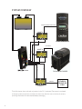
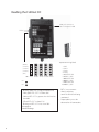
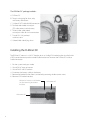
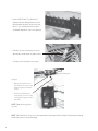
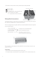
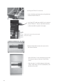
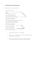
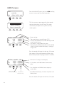
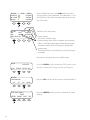
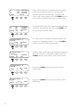
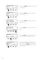
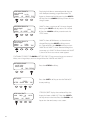
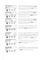
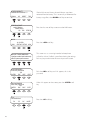
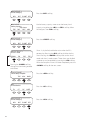
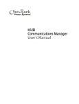
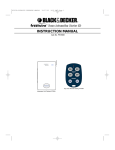
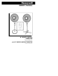
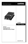
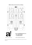
net DC
TM
User’s Guide
Includes Mounting and Installation
Warranty
Dear OutBack Customer,
Thank you for your purchase of OutBack products. We make every effort to assure our power
conversion products will give you long and reliable service for your renewable energy system.
As with any manufactured device, repairs might be needed due to damage, inappropriate use, or
unintentional defect. Please note the following guidelines regarding warranty service of OutBack
products:
• Any and all warranty repairs must conform to the terms of the warranty.
• All OutBack equipment must be installed according to their accompanying instructions and
manuals with specified over-current protection in order to maintain their warranties.
• The customer must return the component(s) to OutBack, securely packaged, properly addressed,
and shipping paid. We recommend insuring your package when shipping. Packages that are not
securely packaged can sustain additional damage not covered by the warranty or can void warranty
repairs.
• There is no allowance or reimbursement for an installer’s or user’s labor or travel time required to
disconnect, service, or reinstall the damaged component(s).
• OutBack will ship the repaired or replacement component(s) prepaid to addresses in the continental
United States, where applicable. Shipments outside the U.S. will be sent freight collect.
• In the event of a product malfunction, OutBack cannot bear any responsibility for consequential
losses, expenses, or damage to other components.
• Please read the full warranty at the end of this manual for more information.
About OutBack Power Systems
OutBack Power Systems is a leader in advanced energy conversion technology. Our products
include true sine wave inverter/chargers, maximum power point tracking charge controllers, system
communication components, as well as breaker panels, breakers, accessories, and assembled systems.
Notice of Copyright
FLEXnet DC User’s Guide © 2007 All rights reserved.
1
Disclaimer
UNLESS SPECIFICALLY AGREED TO IN WRITING, OUTBACK POWER SYSTEMS:
(a) MAKES NO WARRANTY AS TO THE ACCURACY, SUFFICIENCY OR SUITABILITY OF ANY TECHNICAL OR
OTHER INFORMATION PROVIDED IN ITS MANUALS OR OTHER DOCUMENTATION.
(b) ASSUMES NO RESPONSIBILITY OR LIABILITY FOR LOSS OR DAMAGE, WHETHER DIRECT, INDIRECT,
CONSEQUENTIAL OR INCIDENTAL, WHICH MIGHT ARISE OUT OF THE USE OF SUCH INFORMATION. THE
USE OF ANY SUCH INFORMATION WILL BE ENTIRELY AT THE USER’S RISK.
Date and Revision
January, 2008
Contact Information
OutBack Power Systems
19009 62nd Ave. NE
Arlington, WA 98223
Phone (360)435-6030
Fax (360)435-6019
outbackpower.com
2
TABLE OF CONTENTS
Warranty Summary..................................................................................................................................................................... 1
Introduction .................................................................................................................................................................................... 4
System Overview ......................................................................................................................................................................... 5
Reading the FLEXnet DC......................................................................................................................................................... 6
FLEXnet DC Package ................................................................................................................................................................. 7
Installing the FLEXnet DC................................................................................................................................................7-10
FLEXnet DC Measurements ................................................................................................................................................11
Logged Data .................................................................................................................................................................................12
User Adjustable Set Points ...................................................................................................................................................12
Programming and Using the MATE for FLEXnet Operations..........................................................................13
FLEXnet DC Modes...................................................................................................................................................................14
Programming the Auxiliary Relay ....................................................................................................................................16
MATE Screens ....................................................................................................................................................................... 17-28
Technical Notes...........................................................................................................................................................................29
Warranty .................................................................................................................................................................................. 30-31
Warrranty Registration............................................................................................................................................................32
3
Introduction
The OutBack Power Systems FLEXnet DC
The FLEXNet DC collects, monitors and records time-based battery amp, watt and volt data for display
on the OutBack MATE series of products, allowing for more accurate set point adjustments and precise
battery recharging. Five LEDs on the FLEXnet DC act as a state-of-charge indicator bar for a quick status
display.
The FLEXnet DC also offers an auxiliary (AUX) relay that acts like a switch to turn on or off a
user-installed light, alarm, or similar low voltage DC device. It can also be set up as a two-wire auto
generator starter.
The FLEXNet DC works in conjunction with up to three input current shunts (either a FW-SHUNT250 or
FW-SHUNT500, each rated 500A/50mV) also available from OutBack.
Only a single FLEXNet DC is needed for any system using OutBack components.
The FLEXnet DC is not intended to be used with the MATE2M. It is designed to work with the MATE or
the MATE2.
NOTE: • One shunt is included as standard equipment with each OutBack FW500-DC and FW1000-AC
enclosures.
• The shunt(s) cannot be connected to a positive (+) ground system.
4
SYSTEM OVERVIEW
CHARGE CONTROLLER BATTERY -
BAT +
BAT SHUNT C
CHARGE CONTROLLER
SHUNT B
B BAT (-)
C DEVICE
C BAT (-)
FX BATTERY -
B DEVICE
A DEVICE
TM
A BAT (-)
net DC
FX INVERTER/CHARGER
BATTERY -
SHUNT A
OTHER DC
SOURCE OR
LOAD
Think of the input shunts as breaks or junctions in the DC (-) conductor. The current is conducted
as though it were a continuous conductor, but the shunts allow the user to monitor the current,
providing information for more accurate battery recharging.
5
Reading the FLEXnet DC
RJ45 jack connects to
Port 2 or higher in HUB
LEDs*
1
2
3
4
5
6
7
8
9
10
10-postion wiring block
(GREEN)
(YELLOW)
(YELLOW)
(YELLOW)
(RED)
SOC
>90%
80-89% 70-79% 60-69% 50-59%
ON
OFF
• Blinking green LED: Charge parameters met
• Solid green LED: SOC** is above 90%
• Solid red LED: SOC is greater than 49% but less
than 60%
• Off red LED: SOC is above 59%
• Blinking red LED: SOC is less than 50%
*See page 15
**State of Charge
6
1:
2:
3.
4.
5:
6:
7:
8:
9:
10:
BATBAT+
Relay
Relay
C DEVICE SIDE
C BAT (-) SIDE
B DEVICE SIDE
B BAT (-) SIDE
A DEVICE SIDE
A BAT (-) SIDE
• BAT+/- must connect
directly to battery
terminals of the bank being
monitored.
• Proper polarity must be
observed on all connections.
The FLEXNet DC package includes:
A. FLEXnet DC
B. Ten-pin wiring plug for shunt, relay
and battery connections
C. Six feet of CAT5 cable for HUB connection
D. Ten-foot color-coded twisted pair
(TP) cable connects to the battery
E. Three six-foot, color-coded,
twisted pair cables for shunt connections
F. Two #6-32 X 3/8” panhead
machine screws
G. Colored labels identifying shunts
C
D
E
E
A
B
Installing the FLEXnet DC
The FLEXnet DC mounts in a 3/4” DC breaker slot in an OutBack DC breaker bracket installed inside
a FLEXware enclosure or previous model OutBack enclosure. To mount the FLEXnet DC inside an
OutBack enclosure:
1.
2.
3.
4.
5.
6.
Put the system into bypass mode
Shut off all AC input to inverters
Shut off all PV and DC breakers
Disconnect the battery cables at the battery
Remove the breaker bracket from its enclosure by removing the four corner screws
Remove a DC breaker knockout
FLEXnet DC mounts in a DC breaker
slot after removing the breaker
knockout
PV breakers off
7
DC breakers off
• Insert the FLEXNet DC inside the DC
breaker box and through the back side
of the breaker bracket; secure with two
#6-32 X 3/8 panhead machine screws
(included) torqued at 5 to 8 inch-pounds
• Connect all wires to the ten-pin wiring
connector. Do not leave any loose wires!
• Connect each twisted pair to a shunt.
Source/Load Negative
Battery Negative
Example:
• Battery side (green wire in
twisted pair) connects to the
battery negative side of the
shunt
• Device side (white wire in
twisted pair) connects to the
source/load (negative) side of
the shunt
NOTE: Color of wiring jacket
can vary
NOTE: The FLEXNet DC shunts must be connected in the negative (low) side of whatever they monitor.
Otherwise, the unit can be damaged.
8
• Black/White twisted pair connects directly to the battery bank being monitored:
White to BAT (-)
Black to BAT (+)
An appropriate fuse—with a rating of 5 amps
or less and greater than 100 volts
DC—may be placed in the black conductor
BLACK/WHITE TWISTED PAIR
Wiring Block Connections
Color-coded twisted pair 18 AWG connects the wiring block and shunt(s) or battery. The wiring must
be installed with the proper polarity to avoid corrupting the data.
The wires connected to the wiring block should match the color-coded label where the wiring block
inserts into the FLEXnet DC.
•
•
•
•
Green and White/Green
Orange and White/Orange
Blue and White/Blue
Black and White
6’ twisted pair wires with #8 forked spade
terminals connected to the shunts
10’ twisted pair wire with 5/16” ring
terminals connected to the battery bank
The wiring block can accommodate #12 AWG to #26 AWG (2.5 mm2 to .20 mm2) wire with a strip
length of 1/4” (6 mm).
Torque Values
• Five inch-pound maximum torque on each terminal block screw
• 4-5 inch-pound torque is recommended if using the supplied 18 AWG stranded twisted pair wire
9
(Installing the FLEXnet DC continued)
• Insert the 10-pin connector to the wiring block on
the back of the FLEXnet DC.
• Install the CAT5 cable into the RJ45 jack in the back
of the FLEXNet DC. Connect the other end of the
cable to the HUB using Port #2 or higher.
FLEXnet DC removed from the breaker
bracket for clarity.
• Replace the breaker bracket and secure with its
four corner fasteners.
• With all FLEXnet DC wires connected, reinstall the
DC enclosure cover and secure its four Phillips
screws.
• After the cover is installed, reconnect the battery
cables at the battery, turn on all the breakers, and
power up the system.
10
FLEXNet DC Measurements
The FLEXNet DC can measure and record:
Volts for one battery bank*
Amps**
Fo
re
ac
KiloWatts
hc
ha
kWhrs removed from the batteries
nn
el
kWhrs returned to the batteries
Amp hours removed from the batteries
Amp hours returned to the batteries
Battery bank state-of-charge
Lifetime kiloamp hours removed from the batteries***
Days since charge parameters last met
Lowest battery state-of-charge reached
Minimum battery voltage***
Maximum battery voltage***
Maximum amp charged***
Maximum amp discharged***
Maximum kWhrs charged***
Maximum kWhrs discharged***
r
Fo
ch
ea
ps
am
l
ne
an
ch
•
•
•
•
•
•
•
•
•
•
•
•
•
•
•
•
•
*
**
***
11
Battery volt input: 0-80 VDC in .1 volt resolution
2000 amp DC span (+/- 1000 amps DC—net amps are charging, net amps
are discharging), .1 amp resolution
The user can manually reset these data. At any given time, the values
displayed are the most recent since the values were last displayed
Logged Data*
The previous 128 days of data are accessible with the MATE. The data is logged each night at
midnight. Be sure the MATE’s clock is set to the correct local time (refer to your MATE manual).
* Data Logging
User Adjustable Set Points
•
•
•
•
•
•
•
Battery charge factor (65-100%) [see page 29]
Battery bank capacity 0-10000 amp hours
Shunt A, B, C—enabled or disabled
Absorb volts (0-80.0 volts, the maximum voltage the battery can absorb)
Return amps (0-500.0A, the maximum current amperage going into the battery)
Parameters met timer (0-240 minutes, the amount of time allowed to recharge)
AUX Relay Set Points
Manual-On, Auto, Manual-Off—allows the user to turn the Aux Relay on and
off like a manual switch or to set it to Auto and have it function when certain
conditions are met
Volts HI—when user determined high voltage value is met, the Aux activates
Volts LO—the Aux activates when a low voltage value is met
SOC (State-of-Charge) HI—a high state-of-charge activates the Aux
SOC (State-of-Charge) LO—a low state-of-charge activates the Aux
HI Delay—the user can adjust the high set point delay time (in minutes)
LO Delay—the user can adjust the low set point delay time (in minutes)
AUX-INVERT LOGIC—the invert logic function can be activated with a YES or
NO command (see page 16)
12
Programming and Using the MATE for FLEXNet DC Operations
At initial power up, use the MATE (see pages 17-28) to program:
• Battery Bank 20 Hour Capacity (provided by the manufacturer) in amp hours (from 10010,000 amp-hours in ten amp increments)
• Battery charge parameters
•
Return amps: See the manufacturer recommendations or set to 2% of the battery bank
amp hour capacity (e.g. a 1000 amp hour battery bank would set the return amps to 20.0
amps)
NOTE: Older battery banks might require a higher value if the system end of charge amps does not
drop to the 2% level.
•
Battery End-of-Charge Voltage: See the manufacturer recommendations or set .2 volts lower
than the system absorb voltage for 12/24 volt systems and .4 volts lower for 48 volt or higher
systems
• Battery Charge Factor (BCF)
•
•
•
•
The BCF compensates for recharging inefficiency from gassing and heating losses to
assure the battery state-of-charge (SOC) display is accurate by scaling it; the BCF is
programmable from 65% to 100% (see page 29).
If the SOC percentage displays full before the batteries’ user-determined charge settings
are met, decrease the BCF percentage; increase it if the SOC is low.
The default setting is 94%, meaning 94% of the charging current is being used for
recharging and 6% is lost. OutBack suggests maintaining the default setting until the
FLEXNet DC has monitored the system through a few charge/discharge cycles.
Setting the BCF to 100% effectively disables any BCF display changes.
• Charge Parameters Met Time
•
•
•
•
13
During this period, the charge parameters must meet or exceed the user-set charge
parameters before the battery is considered full.
Programmable from 0 to 240 minutes
Setting this time to 0 effectively eliminates any filtering provided by this timer. The first
time the charge parameters are met, the unit will consider the parameters met and
perform accordingly.
The default setting is one minute. Longer or shorter periods may apply to
certain sources such as wind generators or hydros.
FLEXNet DC Modes
-
Channel A is enabled by default
Each input channel is either enabled or disabled.
A disabled channel will show zero values only.
All enabled channels will run in parallel.
An enabled channel monitors and totals all current flowing into or out of the battery
bank through its shunt. Any DC loads or sources wired directly to the battery cannot be
accounted for by FLEXNet and will result in inaccurate readings.
- All unused channels should be set to disabled.
NOTE: All shunts must be connected in the negative or low side of the system and operate in parallel.
High side connection may result in erratic operation and/or failure of the FLEXNet DC.
Charge Cycle
At power up, the FLEXNet DC assumes the battery is full regardless of the battery state-of-charge. The
batteries should receive a full charge at this time to meet the user-determined charge parameters
(entered at start up).
Typical charge cycle:
1. The battery bank is charging and charge parameters are satisfied (return amps, battery
voltage, and the parameters met time set point).
2. When the top green LED is blinking, the charge parameters have been
satisfied.
3. When a discharge begins, an internal timer counts for one minute. After one minute of
discharge, a new discharge cycle starts. All LEDs go solid and all amp hours and kilowatt
hours registers return to zero.
The FLEXNet DC is now synchronized to the battery.
4. The charged and removed amp-hours from the battery are monitored according to the
following:
•
•
•
14
Amp-hours removed from the battery are counted at 100%.
Amp-hours returned to the battery are discounted by the Battery Charge Factor.
The default charge factor is 94% (each amp-hour returned to the battery is accounted for
as 0.94 Amp-Hours).
The FLEXnet DC’s LEDs indicate the SOC by their individual ON/OFF states. Excluding the RED or last
LED, when viewing the remaining four LEDs—GREEN, YELLOW, YELLOW, AND YELLOW— the following
are true:
• All LEDs on = 90-100% SOC
GREEN LED blinking—charge parameters met
Solid GREEN LED—SOC is above 90%
• All but top LED on = 80-89% SOC
• All but top two LEDs on = 70-79% SOC
• Bottom yellow LED on = 60-69% SOC
When viewing the last (RED) LED:
• Bottom RED LED on = 50-59% SOC
• Bottom LED blinking = less than 50% SOC
NOTE: The bottom LED is always off unless the SOC is less than 60%
5. When the SOC is less than 90%, enough of a discharge has taken place that the FLEXnet DC’s data
can be used to determine, among other things, an accurate Battery Charge Factor. A battery amphour charge factor* and the battery kWhr efficiency factor** for the last cycle are calculated using
the stored values from the previous charge cycle (if the SOC is higher than 90%, the values aren’t
reliable enough for these calculations). The battery must cycle at least twice for these values to be
valid.
* Battery amp-hour charge factor = amp-hours removed/amp-hours charged
** Battery kWh efficiency factor= kWhs removed/kWhs charged
(GREEN)
(YELLOW)
(YELLOW)
(YELLOW)
(RED)
ON
OFF
15
> 90%
80-89%
70-79%
60-69%
50-59%
<50%, red LED blinks
Programming the Auxiliary Relay
The FLEXNet DC’s unpowered relay is rated 5 amps/30VDC.
NOTE: This relay is not fused and requires appropriate sized wiring and over-current
protection. Damage due to unprotected relay devices is not covered by the warranty.
The relay may be configured in one of two modes:
1. AUTO activates the relay based on user selected battery voltage, percentage of SOC delay times
and invert logic settings.
2. MANUAL allows direct relay control using the MATE, causing the relay to behave as a switch.
NOTE: When the MATE’s AGS function is active, it will override the AUX set points of whichever component
it has been programmed to control (this should be the AUX connected to the generator). OutBack strongly
recommends using the AGS function of the MATE to control a generator.
AUTO Mode
Six user adjustable set points govern the control logic of AUTO Mode:
1. Vbat Hi (0-99.9Vdc)
2. Vbat Lo (0-99.9Vdc)
NOTE: Relay logic can be inverted
3. %SOC Hi (0-100%)
for these set points
4. %SOC Lo (0-100%)
5. Hi Delay Time in Minutes (0-240 minutes)
6. Lo Delay Time in Minutes (0-240 minutes)
•
•
•
•
If the battery voltage set points are not met, then the %SOC set points are evaluated.
If %SOC set points are not met, then no action is taken.
If either volts or %SOC set points are met, then the delay timer runs.
When the set points have been satisfied for a time (either Hi Delay for the Hi set points met or Lo
Delay for the Lo set points met) the relay is actuated.
• Please see pages 26-28 to set the AUX Mode.
Relay Logic:
• Expressed as NO/NC (Normally Open/Normally Closed), basically off/on
• May be controlled via the invert logic selection from the MATE.
• Toggling the relay logic setting changes the logic mode for Hi or Lo set points
Example: The relay’s contacts are closed when the Hi set point is satisfied and open again when the Lo
set point is achieved. However, you want the relay’s contacts to be open under this condition. Toggling
the invert logic set point will accomplish this. The truth table appears as follows:
Invert Logic
Yes
No
Hi Set Point Satisfied
Relay Open
Relay Closed
The Hi and Lo delay times are set in minutes.
16
Lo Set Point Satisfied
Relay Closed
Relay Open
MATE Screens
MAIN------------------------------11:30:55A
SUM
From the MAIN MATE menu, press the <SUM> soft key
to view a summary of the system’s operation.
STATUS SETUP ADV
E
F
Battery Charging
State of charge 99%
DC NOW
In
Out
Bat
12.5V
0.0A
0.5A
-0.5A
99%
0.000kW
0.000kW
0.000kW
This first summary screen appears for a few seconds
to display the battery State of Charge. The screen
automatically disappears and a system summary
screen appears.
• Battery voltage
• The current battery state-of-charge (SOC)
• In shows the amount of DC current coming into the
system from all sources
• Out shows DC current from the system
• Bat(tery) displays difference between the In and Out
values and shows whether the battery is storing or
using current
Press the second soft key to view the next SUM screen
(the screens will also scroll automatically after a userdetermined period of time programmed in the MATE).
DC Today min/SOC
76%
In
347AH
9.040kWH
Out
331AH
8.510kWH
Bat
16AH
0.530kWH
• Minimum SOC today (since midnight)
• In: Amp hours and kiloWatt hours from sources
today
• Out: Amp hours and kiloWatt hours output by
system today
Press to view
previous days’ history
Press to move
forward one day
• Bat: Difference of battery in and out amp hours and
kiloWatt hours
Press the second soft key to view the next SUM screen
17
FX Total
Inverting
AC Loads
Buying
$
12.6V
99%
0.000kW
0.000kW
0.000kW
DC BAT
12.5V
99%
Bat
-0.6A
0.000kW
Net
-4AH
00.7kWH
Days Since Full
4.8
From the MAIN menu, press the <SUM> soft key to view a
summary of the system’s operation. This information is a sum
of all FlexNet DC data. Press the second soft key to view the
next SUM screen
The fourth SUM screen shows:
• Battery voltage
• The current state-of-charge
• Battery readings show the instantaneous amp, amp hour,
kilowatt, and kilowatt hour figures. When comparing the
amp hours reading to “FULL,” the figure is charge factor
compensated.
• The number of days since the battery last met the charge
parameters.
Press the first soft key to return to the MAIN screen.
MAIN-----------------------------11:30:55A
SUM
STATUS SETUP ADV
STATUS
choose device:
FX
CC
Press the <DC> soft key to view the status of the (FlexNet) DC
DC
MAIN
STATUS/DC/PAGE1 -------------STATS
METER SHUNT BATT TOP
18
Press the <STATUS> soft key to open the STATUS screen to view
the status of either the FX, Charge Controller, or (FLEXnet) DC
Press the <METER> soft key to view the (FlexNet) DC meter
readings.
A:
B:
C:
DOWN
0.1A
0.0A
0.0A
A:
-1AH
B:
0AH
C:
0AH
DOWN
UP
0.000 kW
0.000 kW
0.000 kW
STATUS
0.100kWH
0.000kWH
0.O00kWH
TOP
The second METER screen shows the accumulated amp hours
and kilowatt hours for each shunt. Press the <DOWN> soft
key to view the next METER screen.
METER/DC/SHUNT A
removed
12AH
0.030kWH
DOWN
UP
TOP
This screen shows the number of removed amp hours and
watt hours as measured by SHUNT A. Press the <DOWN>
soft key to view the SHUNT A charged screen.
METER/DC/SHUNT A
charged
12AH
0.160kWH
DOWN
UP
TOP
The fourth meter screen displays the number of charged amp
hours and watt hours as measured by SHUNT A. Press the
<DOWN> soft key to view the first SHUNT B METER screen.
METER/DC/SHUNT B
removed
AH
0kWH
DOWN
UP
TOP
Pressing the <DOWN> soft key brings up the SHUNT B
charged screen.
METER/DC/SHUNT B
charged
AH
0kWH
DOWN
UP
TOP
19
The first METER screen shows the amount of instantaneous
current running through each shunt. A positive value
indicates current flow into the battery; a negative value
means a load is being supplied. Press the <DOWN> soft key
to view the AH and kWH (amp hour and watt hour) screen.
Pressing the <DOWN> soft key brings up the first SHUNT C
METER screen.
METER/DC/SHUNT C
removed
AH
0kWH
DOWN
UP
TOP
Pressing the <DOWN> soft key brings up the SHUNT
C charged screen.
METER/DC/SHUNT C
charged
AH
0kWH
DOWN
UP
TOP
Pressing the <DOWN> soft key brings up the FN
firmware screen.
STATUS/FN/METER
DC firmware revision
000.00/040
DOWN
UP
Pressing the <DOWN> soft key leads to the end of
the meter menu
TOP
STATUS/FN/METER
end of meter menu
UP
TOP STATUS
STATUS/FN
STATS
METER SHUNT BATT TOP
STATUS/DC/SHUNT A
max removed
amps
0.9
DOWN
UP RESET TOP
20
Press the <STATUS> soft key to return to the STATUS
screen.
Press the <SHUNT> soft key to view the amps and
kilowatts removed and charged in each shunt
In this example, SHUNT A has detected 0.9 amps
removed. Press the <RESET> soft key to return this
value to 0. Press the <DOWN> soft key to continue
through the menu.
STATUS/DC/SHUNT A
max removed
kWatts
0.010
DOWN
UP
RESET TOP
Displaying the kilowatts removed provides the user
with more precise energy usage information. This
figure can be returned to 0 by pressing the <RESET>
soft key. Press the <DOWN> soft key to view the max
charged screen.
STATUS/DC/SHUNT A
max charged
amps
39.8
DOWN
UP RESET
TOP
SHUNT A shows a maximum of 39.8 amps charged.
Pressing the <RESET> soft key returns this value to
0. Press the <DOWN> soft key to continue in the
STATUS menu.
STATUS/DC/SHUNT A
max charged
kWatts
0.510
DOWN
UP
RESET
SHUNT A shows 0.510 kilowatts as the maximum
charged. Pressing the <RESET> soft key returns
this value to 0. Press the <DOWN> soft key to view
SHUNT B and SHUNT C values. Proceed through the
same steps as in SHUNT A. When finished with SHUNT
C, the end of shunt status menu screen appears
TOP
CONTINUING TO PRESS THE<DOWN> SOFT KEY LEADS TO max removed amps, max removed
kWatts, max charged amps, and max charged kWatts for SHUNT B and SHUNT C
STATUS/DC/SHUNT
end of shunt
status menu
UP
TOP STATUS
STATUS/DC
STATS
METER SHUNT BATT TOP
STATUS/DC/BATT
total
days
at
100%
0.5
DOWN
UP RESET
21
Press the <STATUS> soft key.
Press the <BATT> soft key to view the FlexNet DC
battery readings
STATUS/DC/BATT displays the number of days the
battery has been at 100% SOC. Press the <RESET>
soft key to restart the timer. Press the <DOWN> soft
key to view the next battery status screen.
STATUS/DC/BATT
days
since
charge
parameters met
5.9
DOWN UP
TOP
STATUS/DC/BATT
battery min today
12.4 vdc
DOWN
UP
RESET
STATUS/DC/BATT
battery max today
12.7 vdc
DOWN
UP
RESET
STATUS/DC/BATT
temp comp’d batt
setpoint 14.2 vdc
DOWN
UP
STATUS/DC/BATT
system battery
temperature
DOWN
UP
STATUS/DC/BATT
cycle charge
factor
78%
DOWN
UP
STATUS/DC/BATT
cycle KwHr charge
efficiency
65%
DOWN
UP
22
TOP
TOP
TOP
29 C
TOP
TOP
TOP
STATUS/DC/BATT provides the number of days since the
battery last met its charge parameters. Press the <RESET>
soft key to restart the timer. Press the <DOWN> soft key to
view the next battery status screen.
batttery min(imum) displays the minimum battery voltage
since it was last reset by the user. Pressing the <RESET>
soft key resets the battery minimum voltage; it also resets
automatically at midnight. Press the <DOWN> soft key to
view the next battery status screen.
batttery max(imum) displays the maximum battery voltage
since it was last reset by the user. Pressing the <RESET>
soft key resets the battery maximum voltage; it also resets
automatically at midnight. Press the <DOWN> soft key to
view the next battery status screen.
temp comp’d batt setpoint shows the temperature compensated end of charge volts when a network RTS is part of the
system. Press the <DOWN> soft key to continue.
When an RTS is present and the temperature is less than 60 C
and greater than10 C, the temperature is displayed in Celsius
(C). Instead of a temperature reading, ### will appear if an RTS
is not present, is damaged, or the temperature is less than
10 C or greater than 60 C. Press the <DOWN>soft key to
continue.
cycle charge factor displays the last cycle amp hours removed
and amp hours returned (as a percentage). Press the
<DOWN> soft key to continue.
cycle KwHr charge efficiency states the last cycle kilowatt hours
removed and kilowatt hours returned (as a percentage). Press
the <DOWN> soft key to view the next screen.
STATUS/DC/BATT
lifetime kAH removed 5
DOWN
UP
RESET
TOP
STATUS/DC/BATT---------------end of battery
status menu
UP TOP STATUS
lifetime kAH removed shows the total kilowatt amp hours
removed from the battery. This is essentially an “odometer” for
battery usage. Press the <DOWN> soft key to continue.
Press the first two soft keys to return to the MAIN menu.
MAIN------------------------------SUM
11:30:55A
STATUS SETUP ADV
ADV/SETTINGS/WARNING
Changes made could adversely
effect system performance
This screen acts as a warning intended to keep those
unfamiliar with an OutBack system from altering the settings.
Push any key to advance to the enter the password screen.
ADV/PASSWORD
enter the password
132
ENTER
INC
DEC
Push the <INC> soft key until 141 appears; this is the
password.
ADV/PASSWORD
enter the password
141
ENTER
INC
DEC
EXIT
When 141 appears on the screen, press the <ENTER> soft
key.
EXIT
ADV-------------------------------choose device:
FX
23
Press the <ADV> soft key.
CC
DC
MATE
Press the <DC> soft key.
ADV/DC/PAGE 1---------------choose category
ADV
BAT
SHUNT PG2
ADV/DC/BAT------------------battery capacity
amp hours
TOP INC
DEC ADV
Use the battery capacity screen to set the battery bank
capacity using either the <INC> or <DEC> soft key. When
finished, press the <TOP> soft key.
ADV/DC/PAGE 1---------------choose category
Press the <SHUNT> soft key.
ADV
BAT
SHUNT PG2
ADV/DC/SHUNT 1 --------------shunt 1 mode
DOWN
EN
DIS
TOP
Pressing the <DOWN> soft key
changes the shunt being enabled
or disabled.
ADV/DC/SHUNT----------------shunt setup complete
TOP
ADV
FX
CC
DC
BAT
Press the <ADV> soft key.
Press the <DC> soft key.
MATE
ADV/DC/PAGE 1---------------choose category
ADV
Shunt 1 is, by default, enabled or active when the FX is
powered up. Pressing the <DIS> soft key disables the first
shunt. Pressing the <DOWN> soft key leads to the shunt 2
mode and shunt 3 mode screens. These shunts are disabled
at power-up and are enabled by pressing the <EN> soft key.
When the setup for all shunts has been completed, press the
<DOWN> soft key for the next screen.
MAIN
ADV-------------------------------choose device:
24
Press the <BAT> soft key.
SHUNT PG2
Press the <PG2> soft key.
ADV/DC/PAGE 2---------------choose category
Press the <CHARGE> soft key.
PG1 CHARGE AUX PG3
ADV/DC/CHARGE-------------return amps
DOWN INC
DEC
TOP
ADV/DC/CHARGE--------------battery charge
DOWN INC
DEC
TOP
Set the end of charge voltage using the <INC> or <DEC>
soft keys. Next, press the <DOWN> soft key.
ADV/DC/CHARGE--------------parameters met time
minutes
DOWN INC
DEC TOP
Press the <INC> or <DEC> soft keys to determine the
amount of time the charge parameters must be met before
they are considered an accurate state of charge. The default
period is one minute. By establishing a time, momentary
spikes in voltage are accounted for. Press the <DOWN> soft
key to view the charge factor screen.
ADV/DC/CHARGE-------------charge factor
%
Set the charge factor (see page 13) using the <INC> and
<DEC> soft keys. When finished, press the <DOWN> soft key.
DOWN INC
DEC
TOP
ADV/DC/CHARGE-------------charge parameters
complete
TOP ADV MAIN
ADV-------------------------------choose device:
FX
25
The return amps screen allows the user to set the end of
charge amps using the <INC> and <DEC> soft keys. Press the
<DOWN> soft key to view the battery charge screen.
CC
DC
MATE
Press the <ADV> soft key.
Press the <DC> soft key.
ADV/DC/PAGE 1---------------choose category
ADV
BAT
Press the <PG2> soft key.
SHUNT PG2
ADV/DC/PAGE 2----------------choose category:
PG1 CHARGE AUX
PG3
ADV/DC/AUX CONTROL-------currently:
Auto On
DOWN
OFF
AUTO ON
ADV/DC/AUX HIGH VOLT-----high volts
vdc
DOWN INC
DEC
TOP
ADV/DC/AUX LOW VOLT-----low volts
vdc
DOWN INC
DEC
TOP
ADV/DC/AUX SOC HIGH-------SOC high
%
DOWN INC
26
DEC
TOP
Press the <AUX> soft key.
Pressing the <OFF> or <ON> soft keys will manually shut the
AUX off (the relay is open) or turn it on (the relay is closed),
respectively. In AUTO mode, the AUX is controlled by userdetermined set points. After setting the AUX control, press
the <DOWN> soft key.
Use the high volts screen and the <INC> and <DEC> soft
keys to control the AUX by a high voltage value. Press the
<DOWN> soft key to view the low volts screen.
Use the low volts screen and the <INC> and <DEC> soft
keys to control the AUX by a low voltage value. Press the
<DOWN> soft key to view the SOC high % screen.
Use the <INC> and <DEC> soft keys to change the SOC high
percentage to trigger the AUX function. Press the <DOWN>
soft key to view the SOC low % screeen.
ADV/DC/AUX SOC LOW-------SOC low
%
DOWN INC
DEC
TOP
ADV/DC/AUX/HI DELAY HIGHhigh setpoint delay
minutes
DOWN INC
DEC TOP
Change the high setpoint delay minutes using the <INC> and
<DEC> soft keys. Press the <DOWN> soft key to continue.
ADV/DC/AUX/LO DELAY HIGHlow setpoint delay
minutes
DOWN INC
DEC TOP
Set the low setpoint delay minutes using the <INC> and
<DEC> soft keys. Press the <DOWN> soft key to continue.
ADV/DC/AUX/INVERT--------invert logic
To activate the invert logic function, press the <YES> soft key;
press the <NO> soft key to deactivate it. Press the <DOWN>
soft key to view the last AUX screen.
DOWN
YES
NO
TOP
ADV/DC/AUX---------------aux parameters
complete
TOP ADV MAIN
ADV-------------------------------choose device:
FX
CC
DC
ADV
BAT
Press the <ADV> soft key.
Press the <DC> soft key.
MATE
ADV/DC/PAGE 1---------------choose category
27
Change the SOC low % values using the <INC> and <DEC>
soft keys. Press the <DOWN> soft key to continue.
SHUNT PG2
Pressing the <PG2> soft key.
ADV/DC/PAGE 2----------------choose category:
PG1 CHARGE AUX
PG3
ADV/DC/AUX/PAGE 3---------choose category:
PG2
RESET
Press the <PG3> soft key.
Pressing the <RESET> soft key resets the FLEXnet DC
to its factory default settings.
CLR MAIN
Pressing the <CLR> soft key clears the data log
memory.
28
Technical Notes
Battery Charge Factor (BCF)
Some energy is lost both when recharging and discharging a battery. The FLEXnet DC
compensates for these losses by discounting the amp-hours charging the battery, meaning
it doesn’t count every hour used for recharging as actually recharging. Some of them are lost
due to heat and gassing. The FLEXnet DC’s default BCF is 94, which means for every 100 amp
hours of charge to the battery, only 94 are shown in the amp hour display for a BCF of 94%.
This means 6% of the amp hours is lost.
As the system goes through a few recharging cycles, the range of state-of-charge (SOC)
percentages will vary, but should fall into a predictable range. This allows the user to change
the BCF if necessary for more efficient recharging. If the SOC displays as full before the battery
charge settings are met (either before the time setting or amp hour setting is satisfied), the
BCF should be lowered because it’s assuming too many amp hours have been recharging the
battery. By lowering the BCF, the FLEXnet DC will read more hours as being unused due to
inefficiency.
29
2-Year Limited Warranty
FLEXnet Products
OutBack Power Systems, Inc. (“OutBack”) provides a two year (2) limited warranty (“Warranty”)
against defects in materials and workmanship for its FLEXnet products (“Products”) if installed
in fixed location applications.
For this Warranty to be valid, the Product purchaser must complete and submit the applicable
Product registration card within ninety (90) days of the eligible Product’s first retail sale. This
Warranty applies to the original OutBack Product purchaser, and is transferable only if the
Product remains installed in the original use location. The warranty does not apply to any
Product or Product part that has been modified or damaged by the following:
•
•
•
•
•
•
•
•
•
•
•
•
•
Installation or Removal;
Alteration or Disassembly;
Normal Wear and Tear;
Accident or Abuse;
Corrosion;
Lightning;
Repair or service provided by an unauthorized repair facility;
Operation contrary to manufacturer product instructions;
Fire, Floods or Acts of God;
Shipping or Transportation;
Incidental or consequential damage caused by other components of the power system;
Any product whose serial number has been altered, defaced or removed; or
Any other event not foreseeable by OutBack.
OutBack’s liability for any defective Product, or any Product part, shall be limited to the repair
or replacement of the Product at OutBack’s discretion. OutBack does not warrant or guarantee
workmanship performed by any person or firm installing its Products. This Warranty does not
cover the costs of installation, removal, shipping (except as described below), or reinstallation
of Products.
Revision.2007-08-29
30
To request warranty service, you must contact OutBack Technical Services at (360) 435-6030
or [email protected] within the effective warranty period. If warranty service is
required, OutBack will issue a Return Material Authorization (RMA) number. A request for an
RMA number requires all of the following information:
1. Proof-of-purchase in the form of a copy of the original Product purchase invoice or receipt
confirming the Product model number and serial number;
2. Description of the problem; and
3. Shipping address for the repaired or replacement equipment.
After receiving the RMA number, pack the Product(s) authorized for return, along with a copy
of the original purchase invoice and warranty certificate, in the original Product shipping
container(s) or packaging providing equivalent protection and mark the outside clearly with
the RMA number. The sender must prepay all shipping charges, and insure the shipment, or
accept the risk of loss or damage during shipment. OutBack is not responsible for shipping
damage caused by improperly packaged Products, the repairs this damage might require, or
the costs of these repairs. If, upon receipt of the Product, OutBack determines the Product is
defective and that the defect is covered under the terms of this Warranty, OutBack will then
and only then ship a repaired or replacement Product to the purchaser freight prepaid, nonexpedited, using a carrier of OutBack’s choice within the continental United States, where
applicable
Shipments to other locations will be made freight collect. The warranty period of any repaired
or replacement Product is twelve (12) months from the date of shipment from OutBack, or the
remainder of the initial warranty term, which ever is greater.
THIS LIMITED WARRANTY IS THE EXCLUSIVE WARRANTY APPLICABLE TO OUTBACK
PRODUCTS. OUTBACK EXPRESSLY DISCLAIMS ANY OTHER EXPRESS OR IMPLIED WARRANTIES
OF ITS PRODUCTS, INCLUDING BUT NOT LIMITED TO ANY IMPLIED WARRANTIES OF
MERCHANTABILITY OR FITNESS FOR A PARTICULAR PURPOSE. OUTBACK ALSO EXPRESSLY
LIMITS ITS LIABILITY IN THE EVENT OF A PRODUCT DEFECT TO REPAIR OR REPLACEMENT IN
ACCORDANCE WITH THE TERMS OF THIS LIMITED WARRANTY AND EXCLUDES ALL LIABILITY
FOR INCIDENTAL OR CONSEQUENTIAL DAMAGES, INCLUDING WITHOUT LIMITATION ANY
LIABILITY FOR PRODUCTS NOT BEING AVAILABLE FOR USE OR LOST REVENUES OR PROFITS,
EVEN IF IT IS MADE AWARE OF SUCH POTENTIAL DAMAGES. SOME STATES (OR JURISDICTIONS)
MAY NOT ALLOW THE EXCLUSION OR LIMITATION OF WARRANTIES OR DAMAGES, SO THE
ABOVE EXCLUSIONS OR LIMITATIONS MAY NOT APPLY TO YOU.
Revision.2007-08-29
31
net DC
TM
Limited Warranty Registration
Complete this form to request a Limited
Warranty and return it to:
Outback Power Systems Inc.
19009 62nd Ave. NE
Arlington, WA 98223
Note: A Limited Warranty Certificate will only be issued if this Registration Card is received by OutBack
within 90 days of the date of the first retail sale of the eligible Product. Please submit a copy (not the
original) of the Product purchase invoice, which confirms the date and location of purchase, the price
paid, and the Product Model and Serial Number.
Two Year Limited FLEXnet DC Warranty Registration
System Owner
Name: _______________________________
Address: ______________________________
City, State, Zip Code: ____________________
Country: _______________________________
Telephone Number:_______________________
E-mail__________________________________
Product
Product Model Number: _________________ Sold by: ________________________________
Product Serial Number: __________________ Purchase Date: ___________________________
Optional Extended Warranty* Coverage? (circle one): Yes
No
Please circle the three most important factors affecting your purchase decision:
• Price
• Product Reputation
• Product Features
• Reputation of OutBack Power Systems
• Value
System
System Install/Commission Date: __________ Type of PV Modules: ______________________
System Battery Bank Size (Amp Hours): ________ System Array Size: ________________________
Type of Batteries: _______________________ System Array Nominal Voltage: ______________
Please List Other sources of Back-up Power: ___________________________________________
______________________________________________________________________________
Devices Being Monitored by FLEXnet DC: _____________________________________________
______________________________________________________________________________
Installer
Installer: ______________________________
Installer Address: _______________________
Installer E-mail: _________________________
Contractor Number: ______________________
Installer City, State, Zip: ____________________
*Extended Warranty - OutBack Power Systems offers an optional three year extension to the standard two year Limited
Warranty in North America for the FLEXnet DC product. To request a 3-year Limited Warranty extension for a total effective
warranty coverage period of five years(5); include a check or money order in the amount of $50USD payable to OutBack
Power Systems, Inc. along with your Warranty Registration.
Revision .2007-09-17
32
Corporate Office
19009 62nd Avenue NE
Arlington, WA USA
Phone: (+1) 360.435.6030
European Sales Office
C/ Castelló, 17
08830 - Sant Boi de Llobregat
BARCELONA, España
Phone: (+34) 93.654.9568
www.outbackpower.com
900-0093-01-00 REV B