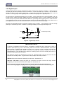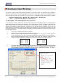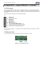
1
iRIS 220 iRIS 320 User Guide For Software Version: V1.19 (Requires Firmware Version: V2.19+) Revision History Issue 1 Issue 2 Issue 3 Issue 4 Issue 5 Version 1.02 Version 1.05 Version 1.10 Version 1.12 Version 1.19 3rd November 2004 17th February 2005 21st July 2005 2nd September 2005 26th July 2006 Initial version Changes for V1.2 PCB / hardware revision Disclaimer Under no circumstances will iQuest (NZ) Ltd be liable or responsible for any consequential damage or loss that may arise from the use of this product. All examples and diagrams shown in this manual and any supplied software examples are intended as a guide to understanding this product, not to guarantee operation. iQuest (NZ) Ltd accepts no responsibility for use of this product based on this information or these examples. Owing to the wide variety of possible applications of this product, you must satisfy yourself as to its suitability to your specific application. © 2006, iQuest (NZ) Ltd All rights reserved. This publication, or any part of it, and any software accompanying it may not be copied, photocopied, reproduced, translated or communicated to any third party, or reduced to electronic medium without prior written permission from iQuest (NZ) Ltd. iQuest (NZ) Ltd - PO Box 15169, Hamilton, New Zealand Tel: +64 7 857-0810 Fax: +64 7 857-0811 Email: [email protected] 1 - iRIS 220 / iRIS 320, V1.19 User Guide Contents 1 Introduction......................................................................................................................................... 4 1.1 About this Manual .......................................................................................................................... 4 1.2 Hardware (PCB) Revision.............................................................................................................. 4 1.3 Support........................................................................................................................................... 4 2 Overview .............................................................................................................................................. 5 2.1 Introduction .................................................................................................................................... 5 2.2 General Characteristics – iRIS 220................................................................................................ 5 2.3 General Characteristics – iRIS 320................................................................................................ 6 2.4 Features ......................................................................................................................................... 7 2.5 Typical Applications ....................................................................................................................... 7 2.6 Technical Specifications – iRIS 220............................................................................................... 8 2.7 Technical Specifications – iRIS 320 / iRIS 320V ........................................................................... 9 2.8 Key Features................................................................................................................................ 10 2.8.1 Terminal Configuration .......................................................................................................... 10 2.8.2 Wireless IP Connectivity (GPRS/CDMA) .............................................................................. 10 2.8.3 Alternative Wireless Connectivity (CSD/SMS) ...................................................................... 10 2.8.4 Power Management .............................................................................................................. 10 2.8.5 Data Logging ......................................................................................................................... 11 2.8.6 Logged Data Array Identification........................................................................................... 12 2.8.7 Alarm Processing .................................................................................................................. 12 2.8.8 Real Time Clock & Calendar................................................................................................. 12 2.8.9 Security.................................................................................................................................. 12 2.8.10 Gateway Communication .................................................................................................... 12 3 Installation......................................................................................................................................... 13 3.1 Removing/Replacing the Electronic Assembly - iRIS 220 ........................................................... 13 3.2 Opening / Closing the Housing - iRIS 320 / iRIS 320V................................................................ 13 3.3 Removing / fitting the SIM card (GSM models only).................................................................... 13 3.4 I/O Connector............................................................................................................................... 14 3.4.1 Internal Battery (iRIS 320 / iRIS 320V only).......................................................................... 14 3.4.2 Internal / External 12V Battery Supply .................................................................................. 15 3.4.3 External (Charger) Power Supply ......................................................................................... 15 3.4.4 Analog Inputs ........................................................................................................................ 15 3.4.5 Digital Inputs.......................................................................................................................... 16 3.4.6 Digital Outputs....................................................................................................................... 17 3.5 Antenna Connection..................................................................................................................... 18 3.6 Mounting – iRIS 220..................................................................................................................... 18 3.7 Mounting – iRIS 320 / iRIS 320V ................................................................................................. 19 4 Configuration .................................................................................................................................... 20 4.1 Terminal Connection .................................................................................................................... 20 4.2 Terminal Cfg................................................................................................................................. 21 4.3 Terminal Menus ........................................................................................................................... 23 4.3.1 Main Menu (Level 1).............................................................................................................. 23 4.3.2 Main Menu (Level 1).............................................................................................................. 24 4.3.3 Comms Cfg (Level 2) ............................................................................................................ 25 4.3.4 GPRS/CDMA-1X Cfg (Level 3) ............................................................................................. 27 4.3.5 Phone List (Level 3) .............................................................................................................. 29 4.3.6 IP Acceptance Cfg (Level 4) ................................................................................................. 29 4.3.7 GPRS/CDMA-1X Schedule Cfg (Level 4) ............................................................................. 30 4.3.8 Sensor Selection (Level 2) .................................................................................................... 31 4.3.9 Sensor Cfg (Level 3) ............................................................................................................. 32 4.3.10 Alarm Selection (Level 4) .................................................................................................... 35 iRIS 220 / iRIS 320, V1.19 User Guide - 2 4.3.11 Alarm Cfg (Level 5) ............................................................................................................. 35 4.3.12 Output Selection (Level 2)................................................................................................... 36 4.3.13 Output Cfg (Level 3) ............................................................................................................ 36 4.3.14 Date/Time Cfg (Level 2) ...................................................................................................... 38 4.3.15 Miscellaneous Menu (Level 2) ............................................................................................ 39 4.3.16 Voice Menu (Level 2) .......................................................................................................... 40 5 Operation........................................................................................................................................... 41 5.1 LED Indicators.............................................................................................................................. 41 5.1.1 Status LED ............................................................................................................................ 41 5.1.2 Diagnostic LEDs.................................................................................................................... 41 5.2 LCD & Keypad (iRIS 320 only) .................................................................................................... 42 5.2.1 LCD Operation ...................................................................................................................... 42 5.2.2 Status Icons........................................................................................................................... 42 5.2.3 Keypad Buttons ..................................................................................................................... 42 5.2.4 Display Menu Structure ......................................................................................................... 43 5.2.5 Primary LCD Display Screens............................................................................................... 44 5.2.6 Sensor Related Screens ....................................................................................................... 45 5.2.7 Totaliser Related Screens ..................................................................................................... 47 5.2.8 Comms Related Screens ...................................................................................................... 48 5.3 SMS Communication ................................................................................................................... 51 5.4 General Hints ............................................................................................................................... 52 6 Sensor Connection Examples......................................................................................................... 53 6.1 Connecting a Flow Meter or Rain Gauge .................................................................................... 53 6.2 Connecting a 0-5V Pressure Transducer .................................................................................... 54 6.3 Connecting a 2-Wire Loop-Powered 4-20mA Sensor.................................................................. 55 6.4 Connecting an Up/Down Water Level Instrument........................................................................ 56 6.5 Connecting Analogue Wind Instruments ..................................................................................... 57 6.6 Connecting SDI-12 Instruments. (iRIS 320 / iRIS 320V only) ..................................................... 58 6.7 Connecting a Vaisala WXT510 Weather Transmitter (iRIS 320 only) ......................................... 59 7 Analogue Input Scaling.................................................................................................................... 60 7.1 Example: A 4-20mA Water Level Sensor .................................................................................... 60 8 Troubleshooting ............................................................................................................................... 61 8.1 IRIS will not start when battery is first connected ........................................................................ 61 8.2 Unable to connect to GPRS network ........................................................................................... 61 8.3 Unable to connect to CDMA network........................................................................................... 61 8.4 iRIS will not respond to SMS requests......................................................................................... 61 8.5 iRIS will not answer CSD data calls............................................................................................. 61 8.6 Pulse lost when iRIS connected to other equipment ................................................................... 61 9 User Notes......................................................................................................................................... 62 2 iQuest (NZ) Ltd - PO Box 15169, Hamilton, New Zealand Tel: +64 7 857-0810 Fax: +64 7 857-0811 Email: [email protected] 3 - iRIS 220 / iRIS 320, V1.19 User Guide 10 Appendix A – Radio Using the RS232 Interface .......................................................................... 63 11 Appendix B – Voice Annunciation (iRIS 320V) ............................................................................ 64 12 Appendix C – SDI-12 (iRIS 320 / 320V only) ................................................................................. 65 13 Appendix D – Legacy PCB (Rev 1.1) Details................................................................................ 67 13.1 I/O Connector............................................................................................................................. 67 13.2 Debounce Links ......................................................................................................................... 67 13.3 SDI-12 Interface ......................................................................................................................... 68 13.4 Diagnostic LEDs......................................................................................................................... 68 13.5 Transistor Switch........................................................................................................................ 69 14 Appendix E – iRIS 320 Enclosure Material Spec ......................................................................... 70 15 Appendix F - Network Settings for iQuest APN or iQuest Global Data Network ..................... 71 Tables / Figures Table 1- Feature Summary................................................................................................................................ 7 Table 2 - Standard Sensor Sources ................................................................................................................ 32 Table 3 - Internal Sensor Sources................................................................................................................... 32 Table 4 – Supplementary Logging Flag Definitions......................................................................................... 33 Table 5 – Status LED Indication Modes .......................................................................................................... 41 Figure 1 - iRIS 220............................................................................................................................................. 5 Figure 2 - iRIS 320 / iRIS 320V ......................................................................................................................... 6 Figure 3 - SIM Carrier ...................................................................................................................................... 13 Figure 4 - I/O Connector .................................................................................................................................. 14 Figure 5 - Analog Input Circuit......................................................................................................................... 15 Figure 6 - Digital Input Circuit .......................................................................................................................... 16 Figure 7 - Digital Output 1 Circuit .................................................................................................................... 17 Figure 8 - Digital Output 2 Circuit .................................................................................................................... 17 Figure 9 - iRIS 220 Mounting Diagram ............................................................................................................ 18 Figure 10 - iRIS 320 / iRIS 320V Mounting Diagram....................................................................................... 19 Figure 11 - RS232 Cable Pin Designations..................................................................................................... 20 Figure 12 – Terminal Menu Structure.............................................................................................................. 23 Figure 13 – Typical RS232 / Data Radio Cable .............................................................................................. 63 Figure 14 – Typical RS232 / Radio Modem Cable .......................................................................................... 63 Figure 15 – V1.1 PCB Debounce Links........................................................................................................... 67 Figure 16 - Legacy SDI-12 Interface Connections .......................................................................................... 68 Figure 17 - Transistor Switch - Module Overview ........................................................................................... 69 Figure 18 - Transistor Switch - Circuit Diagram .............................................................................................. 69 iRIS 220 / iRIS 320, V1.19 User Guide - 4 1 Introduction 1.1 About this Manual This manual is intended as a detailed guide for iRIS 200 / iRIS 320 installation, configuration and operation. For a brief operational overview, see the separate iRIS 220 Installation Guide or iRIS 320 Installation Guide. This manual is also available online in Adobe Acrobat® pdf format for registered users at www.iquest.co.nz NOTE: The term “iRIS” is used throughout this manual in all instances where the reference is equally applicable to either the iRIS 220 or the iRIS 320. When a particular section applies to only one of the models, the full model reference will be used. NOTE: The term “GPRS/CDMA-1X” is used throughout this manual to refer to the wireless modem connectivity. However, the terminal menus or LCD screens on the iRIS itself will display the correct designation for the particular model e.g. “GPRS” or CDMA-1X”. 1.2 Hardware (PCB) Revision As from firmware version 2.19 / software version 1.19, this manual has been completely updated to refer to the new version PCB (V1.2). This hardware revision has the following changes over its predecessor: • • • • Two additional analogue inputs added. Dedicated 5V reference output for energising potentiometer type sensors. Digital Output 1 changed to a switched 12V output instead of open-drain pull-down. An external transistor switch is not required for powering sensors. SDI-12 interface has been upgraded to full compliance with the SDI-12 electrical standard and to free up the digital I/O that were required for the SDI-12 function on the older hardware. Legacy I/O and SDI-12 details referring to the older PCB revision can be found in Appendix D – Legacy PCB (Rev 1.1) Details. 1.3 Support Technical support for the iRIS 220 and iRIS 320 is available by contacting: iQuest (NZ) Ltd P.O Box 15169 Hamilton NEW ZEALAND Tel: +64 7 857-0810 Fax: +64 7 857-0811 Email: [email protected] For latest information and software updates, visit the iQuest (NZ) Ltd web site at www.iquest.co.nz 4 iQuest (NZ) Ltd - PO Box 15169, Hamilton, New Zealand Tel: +64 7 857-0810 Fax: +64 7 857-0811 Email: [email protected] 5 - iRIS 220 / iRIS 320, V1.19 User Guide 2 Overview 2.1 Introduction The iRIS 220 and iRIS 320 (iQuest Remote Information Source) are two related products that share similar electronic components and operate in much the same way. They have been designed as cost effective, low power, self contained information sources for use in a wide range of data gathering and logging applications. Both models achieve GPRS or CDMA network connectivity through the use of an integral wireless modem. Depending on the application and target market, this modem will be one of the following: • • • Dual-band 900MHz/1800MHz GSM/GPRS Single-band 1900MHz GSM/GPRS CDMA/CDMA-1X This modem also supports the alternative GSM or CDMA connection options of CSD (Circuit Switched Data) and SMS (Short Message Service). These options require the appropriate service to be enabled by the wireless service provider. The two units differ primarily in their available features and also the enclosure design. The following two sections explain the key differences between the two models. 2.2 General Characteristics – iRIS 220 The iRIS 220 is supplied in a lightweight extruded aluminium enclosure finished in a resilient powder coating. This enclosure provides mechanical strength and EMI shielding, and also enables easy mounting in a variety of situations. The iRIS 220 supports a maximum of six external sensors (1-6). Sources for these sensors may be chosen from physical digital or analog inputs or virtual sources (via serial communication or internal calculations). Each sensor has two associated alarms, each with separate trigger and reset levels. Each alarm also has a duration, which is used to delay the alarm trigger for analog inputs and to determine the time over which pulse input counters should be totalised (for rainfall etc). Three additional sensors (7-9) are reserved for internal measurements (battery voltage, supply voltage and logger temperature). Data from all enabled sensors are logged in a four word (8 byte) compressed format which includes full date and time to fractions of a second. Figure 1 - iRIS 220 iRIS 220 / iRIS 320, V1.19 User Guide - 6 2.3 General Characteristics – iRIS 320 The iRIS 320 is supplied in an environmentally sealed (IP65) enclosure constructed from a special corrosionresistant aluminium alloy that is finished in a hard-anodised coating. This provides a very high degree of mechanical strength and EMI shielding, and enables completely stand-alone mounting in outdoor situations. The unit comes standard with an integral 12V gel-cell battery, membrane keypad and a 4 lines x 12 characters (plus icons) LCD. The iRIS 320 supports a maximum of six external sensors (1-6). Sources for these sensors may be chosen from physical digital or analog inputs or virtual sources (via serial communication or calculations). Each sensor has two associated alarms, each with separate trigger and reset levels. Each alarm also has a duration, which is used to delay the alarm trigger for analog inputs and to determine the time over which pulse input counters should be totalised (rainfall etc). Three additional sensors (7-9) are reserved for internal measurements (battery voltage, supply voltage and temperature). Data from all enabled sensors are logged in a four word (8 byte) compressed format which includes full date and time to fractions of a second. The iRIS 320 supports SDI-12 communication with a range of industry standard intelligent sensors. Refer to Appendix C – SDI-12 (iRIS 320 / 320V only) for more details on the SDI-12 interface. A variant of the iRIS 320, designated the iRIS 320V offers voice annunciation of sensor values using the voice bearer of the wireless service. See Appendix B – Voice Annunciation (iRIS 320V) for details on this model. The iRIS 320 (from PCB revision 1.2) is able to manage a serial camera, the iRIS-CAM (via a small adaptor module). This enabled the iRIS to capture colour images which can be unloaded in the same way as logged data. Due to resource limitations, the iRIS 320V is unable to support the iRIS-CAM in conjunction with the voice feature. Figure 2 - iRIS 320 / iRIS 320V 6 iQuest (NZ) Ltd - PO Box 15169, Hamilton, New Zealand Tel: +64 7 857-0810 Fax: +64 7 857-0811 Email: [email protected] 7 - iRIS 220 / iRIS 320, V1.19 User Guide 9 2 9 2 *SDI-12 Interface supports up to a maximum of 6 channels with the exception of the Vaisala WXT510 option that caters for the special case of seven parameters (see Section 6.7). Table 1- Feature Summary 2.5 Typical Applications The iRIS can be used for a wide range of diverse applications, including but not limited to: Rainfall measurement Water / power / gas metering Remote control River level monitoring Wind measurement Mobile temperature monitoring Irrigation monitoring / control GPRS/CDMA-1X RS232 serial communication gateway Keypad / LCD External RF Antenna Connector 2 Direct Solar Panel Connection Internal Battery Charger Internal 12V Rechargeable Battery Internal 3.6V Lithium Backup Battery 2 9 Heavy Duty Milled Case 2 4 IP65 Rated 4 2 Alarms per Channel (sensors 1-6) 2 Supply Voltage Logging Internal Battery Logging Internal Temperature Logging 2 Number of Simultaneous Logging Channels 4 RS-232 Interface iRIS 320V 2 SDI-12 Interface * iRIS 320 Digital Control Outputs Analog Inputs (0-5V, 0-20mA with resistor) Digital inputs (pulse, frequency counter) CSD Mode IRIS-CAM Camera Support SMS Mode iRIS 220 Voice Annunciation Support GPRS or CDMA Mode 2.4 Features iRIS 220 / iRIS 320, V1.19 User Guide - 8 2.6 Technical Specifications – iRIS 220 Dimensions: 100mm x 172mm x 40mm (3.93in x 6.77in x 1.57in) (Excluding connectors) Mass: 380g (13.4oz) Power Supply: External regulated 12V dc power supply or rechargeable sealed lead-acid battery. Charger Source - External 15-30V dc supply. Supports a directly connected solar panel (no regulator required). Power Consumption: Less than 3mA @ 12V in idle mode and full power save mode selected. Actual current consumption is dependent on power management mode, wireless modem state and I/O configuration. Comms Interfaces: 1x RS232 DB9, 38400 bps, DTE configuration. 1x Integral dual-band (900/1800MHz) GSM/GPRS modem or Integral single-band (1900MHz) GSM/GPRS modem or Integral CDMA/CDMA-X modem Digital I/O: 2 x Digital Inputs - 30Vdc maximum input, switch to 0Vdc to activate. - Link selectable for either mechanical (<20Hz) or electronic (<5kHz) switching. 2 x Digital Outputs - 1 x Switched 12V out (max 300mA) - 1 x Open-drain pull-down (max 300mA @ 30V) Analog I/O: 4 x 12 bit uni-polar analog inputs. Range 0-5000mV. Input impedance 98kΩ. Referenced to 0V common. Internal measurements available for monitoring are: • Battery Voltage • Supply Voltage • Internal Temperature (°C or °F) • Received Signal Strength Indication (RSSI) Logging Memory: Non-volatile 2MB flash storage of 262,144 time/date stamped data points. Circular buffer mode (overwrites oldest data when memory is full). A typical site with 2 parameters logged every 15 minutes plus battery voltage logged hourly will give 3.3 years of storage before data overwrite occurs. Clock/Calendar: Non-volatile with integral lithium back-up battery. Leap year recognition. Accurate to +/-20 secs month, trimmable via a configuration register. Mounting: 4 x M4 (3/16”) mounting holes at ends of case. Environmental: Storage Temperature: -20°C - +85°C. (-4°F - +185°F) Operating Temperature: -10°C - +70°C. (14°F - +158°F) 8 iQuest (NZ) Ltd - PO Box 15169, Hamilton, New Zealand Tel: +64 7 857-0810 Fax: +64 7 857-0811 Email: [email protected] 9 - iRIS 220 / iRIS 320, V1.19 User Guide 2.7 Technical Specifications – iRIS 320 / iRIS 320V Dimensions: 117mm x 162mm x 67mm (4.60in x 6.37in x 2.64in) (Excluding glands and mounting plate) Mass: 1580g (3.48lb) Power Supply: Internal 12V @ 0.8A/Hr rechargeable sealed lead acid battery. Can also connect external regulated 12V dc power supply or rechargeable sealed lead-acid battery. Charger Supply: External 15-30Vdc supply. Supports a directly connected solar panel (no regulator). Power Consumption: Less than 3mA @ 12V in idle mode. Actual current consumption is dependent on power management mode, wireless modem state and I/O configuration. Comms Interfaces: 1x RS232 DB9, 38,400 bps, DTE configuration. 1x Integral dual-band (900/1800MHz) GSM/GPRS modem or Integral single-band (1900MHz) GSM/GPRS modem or Integral CDMA/CDMA-1X modem. Digital I/O: 2 x Digital Inputs - 30Vdc maximum input, switch to 0Vdc to activate. - Link selectable for either mechanical (<20Hz) or electronic (<5kHz) switching. 2 x Digital Outputs - 1 x Switched 12V out (max 300mA) - 1 x Open-drain pull-down (max 300mA @ 30V) Analog I/O: 4 x 12 bit uni-polar Analog inputs. Range 0-5000mV. Input impedance 98kΩ. Referenced to 0V common. Internal measurements available for monitoring are: • Battery Voltage • Supply Voltage • Internal Temperature (°C or °F) • Received Signal Strength (RSSI) SDI-12 Interface: SDI-12 hardware interface that fully complies with the SDI-12 electrical standard. Software support to SDI-12 standard 1.2. Logging Memory: Non-volatile 2MB flash storage of 262,144 time/date stamped data points. Circular buffer mode (overwrites oldest data when memory full). A typical site with 2 parameters logged every 15 minutes plus battery voltage logged hourly will give 3.3 years of storage before data overwrite occurs. Audio Memory: iRIS 320V only. Non-volatile 2MB flash storage of PCM audio files. Total cumulative playtime 3 minutes at 11.025kHz sampling rate. Clock/Calendar: Non-volatile with integral lithium back-up battery. Y2K compliant with leap year recognition. Accurate to +/-20 secs month, trimmable via a configuration register. Mounting: 4 x M4 (3/16”) blind mounting holes in rear of case. Mounting plate supplied as standard accessory for wall or panel installation. 2 x 16mm (¾”) compression glands for power supply and I/O cabling access. 1 x 25mm (1”) compression gland for antenna / RF cable access Front secured by three M5 Allen Key® screws. The two (left-hand) screws act as hinge links. The third (right-hand) screw can be locked with a tamper-proof wire seal. Environmental: Storage Temperature: -20°C - +85°C. (-4°F - +185°F) Operating Temperature: -10°C - +70°C. (14°F - +158°F) Enclosure sealed to IP65 with gasket and glands. iRIS 220 / iRIS 320, V1.19 User Guide - 10 2.8 Key Features 2.8.1 Terminal Configuration All configuration and set-up parameters are modified via a standard ASCII terminal connected to the RS232 serial interface. This means that the user can configure the device without needing specialised configuration software installed on their computer specifically for this purpose. iQuest also supply a network based terminal program (UDPTerminal) that allows set-up to be performed across the GPRS/CDMA-1X network via ASCII socket A. Refer to Section 4.2 for details on the terminal setup. 2.8.2 Wireless IP Connectivity (GPRS/CDMA) Wireless Internet Protocol connectivity is provided via an on-board modem. Through this interface it is possible to perform configuration changes and retrieve logged data. To facilitate GPRS connectivity with the GSM models, a suitably activated SIM card must be inserted in the device. For all models, it is also necessary to program the unit with appropriate GPRS/CDMA-1X connection settings via a terminal connected to the RS232 serial interface. The iRIS communicates over a GPRS or CDMA-1X network using UDP protocol via two concurrent data ports. Port A is used for ASCII communication and provides similar terminal functionality to that available through the RS232 serial interface. Port B is used for proprietary System DO (binary) communication and supports time series data retrieval and unsolicited alarm call-in to a HydroTel™ 2000 base station. This port is also used for auto reporting of data to a suitable base station such as the iQuest Data Network (http://data.iquest.co.nz), when the iRIS has been configured to use this mode. 2.8.3 Alternative Wireless Connectivity (CSD/SMS) Two other wireless connection modes other than GPRS/CDMA-1X are also possible. These are CSD (Circuit Switched Data) or SMS (Short Message Service). As with the GPRS/CDMA-1X mode described above in Section 2.8.2, using either CSD and/or SMS requires either a SIM card with relevant services enabled by the GSM service provider, or in the case of CDMA-1X, the appropriate services enabled by the CDMA provider. The CSD option is achieved by establishing a dial-up modem connection across the GSM or CDMA network. Once this link is connected, data retrieval and configuration can be performed in a similar manner to the GPRS/CDMA-1X mode. The SMS option works by sending a preset text message to up to two destination cellphones or SMS receivers. This message contains the iRIS site identification and the current values of all enabled sensors. See Section 5.3 for more information on using the SMS feature. NOTE: No matter what the modem callback mode is set to (GPRS/CDMA-1X or CSD or SMS), the iRIS will answer any incoming CSD calls and also respond to incoming SMS requests as long as it is not connected using the wireless IP link. The modem callback mode setting only changes the service that is used to notify an alarm or generate a communication test. In this case the selected service and destination phone number is used to call a base modem (CSD) or send a text message (SMS). 2.8.4 Power Management The iRIS supports three power management modes: No Power Save With power management disabled, the internal wireless modem is maintained in a powered on state whenever a GPRS/CDMA-1X or CSD session is not currently active. While in this state, periodic signal strength measurements are made and it is possible to interrogate the internal modem using the AT command set via a terminal connected to the serial interface. All on-board communication, I/O and status LED’s are permanently enabled in this mode. 10 iQuest (NZ) Ltd - PO Box 15169, Hamilton, New Zealand Tel: +64 7 857-0810 Fax: +64 7 857-0811 Email: [email protected] 11 - iRIS 220 / iRIS 320, V1.19 User Guide Partial Power Save With the power management mode set to partial save, the on-board LEDs are disabled but the internal wireless modem remains in the fully active state as with the no power save mode. Full Power Save When power management is set to full save mode, the internal LED’s are disabled and the internal wireless modem remains in a powered off state until a GPRS/CDMA-1X or CSD or SMS session is activated. NOTE: While the modem is in this state, it is not possible to obtain signal strength measurements or interrogate the modem via the AT command set using the Modem Terminal mode. Additional power management features that operate in all modes include: • • • Deactivation of RS232 driver ic when the DSR signal is not present. Disabling the LCD and turning off the backlight after two minutes of no activity. Ability to activate a GPRS/CDMA-1X session at scheduled times of day for pre-set period. 2.8.5 Data Logging The iRIS supports the logging of data from six virtual sensors, plus a further three internal data sources (battery voltage, supply voltage and logger temperature). Each of the six virtual sensors can obtain information from one of the following data sources: • • • • • • • • • • • • • • • Analog Input 1 Analog Input 2 Analog Input 3 Analog Input 4 Pulse Counter attached to Digital Input 1 Pulse Counter attached to Digital Input 2 Simulated Pulse Counter enabled by Digital Input 1 Simulated Pulse Counter enabled by Digital Input 2 Frequency Counter attached to Digital Input 1 Frequency Counter attached to Digital Input 2 Up/down Counter attached to Digital Inputs 1 & 2 Received Signal Strength Indication (RSSI) Internal Database Location (for data obtained via user script or communications link) High-speed Serial Instrument (Unidata format) SDI-12 serial channel Each sensor can be set up to scale the raw data source into engineering units through the application of a multiplier and offset (slope and constant). The scaled value can be logged to non-volatile memory at rates between once per minute to once per hour or on event for pulse inputs. As all logged data is stored in integer format, a logging multiplier is applied to the scaled value to maintain resolution. See Section 4.3.9. It is also possible to configure a sensor to also log minimum, maximum, standard deviation or a calculated flow rate (pulse source only) values. See the next section, Section 2.8.6 and also Section 4.3.9 for further details on configuring these extended logging features as part of the Sensor Cfg menus. iRIS 220 / iRIS 320, V1.19 User Guide - 12 2.8.6 Logged Data Array Identification Each sensor’s logged data is identified by an array ID number. For the primary logged data, the ID is the sensor number itself. For the optional supplementary data (min/max/deviation/flow), the array ID has an offset added to the sensor number that it is derived from. These ID offsets are as follows: Minimum: Maximum: Deviation: Flow Rate +10 +20 +30 +40 For example, Sensor 4 has been configured to log the average value, plus the maximum and standard deviation. Three data arrays will be logged for this sensor at each logging interval with IDs of 4, 24 and 34 respectively. In HydroTel™ 2000 these relate to point identifiers of 4/0, 24/0 and 34/0. 2.8.7 Alarm Processing Each virtual sensor can be checked for two separate alarm conditions. Each alarm has separate trigger and reset levels, as well as an activation delay or accumulation period depending upon the data type. The alarm on Sensor 1 can also be used to control the digital outputs. See Sections 3.4.6 and 4.3.12 for further details on digital outputs. 2.8.8 Real Time Clock & Calendar The iRIS has a non-volatile real time clock that can be set by the user either through a terminal (RS232 or UDP) or remotely via proprietary System DO commands from software such as HydroTel™ 2000 or iLink. To enable user adjustment to minimise clock drift a menu option is provided to set a compensation offset for fine control. See Section 4.3.14. 2.8.9 Security The iRIS 320 can be configured with a PIN code to prevent unauthorised access to restricted information through the LCD and keypad. This is especially useful when the iRIS 320 is installed in a location where it is accessible to the general public. Note: This feature is not available on the iRIS 220 as it has no keypad/LCD interface. 2.8.10 Gateway Communication The iRIS supports System DO gateway functionality between the GPRS/CDMA-1X network and the RS232 serial interface. This enables the unit to be used as a bridge between the wide area GSM/CDMA-1X network and a localised network. It is possible to connect a datalogger that does not have wireless capability such as the iQuest DS-4483 to the serial port of the iRIS and communicate with it via the gateway. Also, by connecting a data radio to the unit’s serial port it is possible to communicate with several devices in a multidrop radio network from the GPRS/CDMA-1X network. The gateway transparently redirects System DO packets received via GPRS/CDMA-1X from address 0 back out the serial port if they are not destined for the iRIS. Conversely, packets received on the serial port from any address and directed to address 0 will be transparently redirected onto the GPRS/CDMA-1X network. To enable gateway functionality it is necessary to activate the RI input on the serial port. This can easily be achieved by connecting the RI and DTR pins of the RS232 connector together. When the iRIS detects the presence of RI, it forces the serial port into System DO mode at 1200 baud. Refer to Appendix A – Radio Using the RS232 Interface for further information on using the RS232 port in this mode. 12 iQuest (NZ) Ltd - PO Box 15169, Hamilton, New Zealand Tel: +64 7 857-0810 Fax: +64 7 857-0811 Email: [email protected] 13 - iRIS 220 / iRIS 320, V1.19 User Guide 3 Installation 3.1 Removing/Replacing the Electronic Assembly - iRIS 220 The electronic assembly is retained in the case by two end plates and held in place by the two connectors (I/O and RS232). Follow this procedure to gain access to the printed circuit board (PCB) to change the SIM card on GSM models (see Section 3.3) or to change the digital input links (see Section 3.4.5). To Remove: Undo the two mounting screws at the antenna end of the case (if fitted). Unplug the I/O connector. Unscrew the two retaining screws on the RS232 connector and remove the connector extension. The PCB can then be carefully removed by sliding it out of the outer case. NOTE: Once the I/O connector and RS232 connector extension have been removed, the PCB is no longer retained. Take care to prevent the PCB falling out of the case. To Replace: Reverse the removal procedure to reassemble the unit. 3.2 Opening / Closing the Housing - iRIS 320 / iRIS 320V The front of the iRIS 320 enclosure is secured by three M5 machine screws with Allen Key® heads. NOTE: The two left-hand screws act as links to the hinges and should not be fully unscrewed. To Open: Undo the right-hand screw completely and put in a safe place. Undo the two left-hand screws until their heads are just fully clear of the front’s face. The front should then be able to be swung open to the left, to a maximum angle of 90°. To Close: Check that the green gasket is fully installed in its retaining groove. Gently swing the front closed to the right, pulling it slightly forwards if it appears to catch, before finally pressing it fully home and then tightening the three M5 screws securely to maintain the IP65 rating of the enclosure. Fit a new tamper-proof wire seal to the right-hand screw if required for security purposes. Slight adjustment of the screw may be required to align the holes in the screw and enclosure to enable the seal’s wire to be passed through. 3.3 Removing / fitting the SIM card (GSM models only) Important! Ensure the iRIS is depowered before attempting to remove or fit the SIM card. Using a fingernail or small screwdriver inserted into one of the two oval holes on the sliding holder, gently lower the slide downwards to unlock it. The slide can now be swung forwards from its top end to enable the SIM card to be inserted or removed. Reverse the procedure to close and lock the card into place. Caution: Exercise care when inserting or removing the SIM card, as the carrier is fragile. SIM Nail / tool access here Unlock Figure 3 - SIM Carrier iRIS 220 / iRIS 320, V1.19 User Guide - 14 3.4 I/O Connector All I/O and power supply terminations are via 5mm (0.2”) screw terminals provided on a 16-way pluggable connector. The older (V1.1) PCB has a 12 way connector - see Appendix D – Legacy PCB (Rev 1.1) Details. The I/O connector is positioned on the right hand side of the iRIS 320 circuit board, directly above the white battery connector. On the iRIS 220, the connector protrudes through the top of the case. The function of each I/O termination is shown in the diagram below. TOP AI4 AI3 AI2 AI1 AGND 5VOP DI2 DI1 DO2 DO1 SDI-12 DGND 12V+ GND (-) VIN+ GND (-) Analog Input #4 Analog Input #3 Analog Input #2 Analog Input #1 Analog Common Ground 5V Reference Output Digital Input #2 Digital Input #1 Digital Output #2 Digital Output #1 SDI-12 Data Bus Digital Common Ground 12Vdc Internal/External Battery Supply + 0Vdc Internal/External Battery Supply 15-30Vdc External Power Supply (Charger Input) + 0Vdc External Power Supply (Charger Input) - BOTTOM Figure 4 - I/O Connector 3.4.1 Internal Battery (iRIS 320 / iRIS 320V only) The iRIS 320 / iRIS 320V are supplied with an internal rechargeable 12V 0.8A/Hr sealed lead-acid battery. Upon installation, you will need to connect this battery as it is shipped disconnected to preserve battery life. It should also be disconnected if the unit is not going to be used for some time. NOTE: The iRIS 220 does not have an internal battery, so ignore all references to the internal battery for the iRIS 220 models. For maximum flexibility, the iRIS I/O connector has two terminals provided for additional 12V power supply flexibility. These terminals (marked 12V+ and GND) can either be used to deliver 12V from the internal battery out to power an external sensor or other small load, or alternatively be connected to an external 12V battery (for greater battery capacity) or a 12V d.c battery charger type power supply. See the next two sections on using the 12V terminals and the external (charger) power supply feature. WARNING! iRIS 320 / iRIS 320V INTERNAL BATTERY The +12V and GND terminals of the I/O connector are effectively connected directly in parallel with the internal 12V battery. A resettable semiconductor fuse is fitted for short-circuit protection. However, only connect 12V lead-acid batteries or a regulated d.c power supply that is designed for charging a 12V lead-acid battery, to these terminals. Applying a voltage higher than 14.5V for a sustained period to these terminals will permanently damage the internal battery and may cause an acid leak and/or an explosion. 14 iQuest (NZ) Ltd - PO Box 15169, Hamilton, New Zealand Tel: +64 7 857-0810 Fax: +64 7 857-0811 Email: [email protected] 15 - iRIS 220 / iRIS 320, V1.19 User Guide 3.4.2 Internal / External 12V Battery Supply For all models there are two terminals provided on the I/O connector designated +12V and GND (or –12V on old models). These can be used to power the unit from an external 12V battery or regulated dc supply. For the iRIS 320 / iRIS 320V models, the internal battery is effectively connected directly to these terminals. See Section 3.4.1 for warnings on connecting external power supplies to them. 3.4.3 External (Charger) Power Supply Although the iRIS 320 can operate solely from its internal battery for a few days, you will typically need to connect an external supply to the unit so that the internal battery remains in a charged state. You can connect any external dc power source ranging from 15 – 30Vdc, including a solar panel, without requiring an additional solar regulator. The battery charging circuitry utilises a switch mode regulator for maximum efficiency. The external power supply is protected against over-voltage by ultra-fast acting protection devices and a self-resetting semiconductor fuse. It can also be used to charge an external battery connected to the GND and 12V+ terminals. In the event that the external battery draws excessive current, the charger will enter a current limit mode (900mA) until such time as the battery has been recharged sufficiently to deliver the full supply voltage. The charging profile used by the charger depends on the selected mode. See the Power Management description in Section 4.3.1. 3.4.4 Analog Inputs The four analogue inputs are uni-polar 0-5Vdc with 12-bit resolution. Each input presents a load impedance of 98KΩ to the input signal. Scaling factors should be chosen to convert from a raw value of 0-5000, which reflects the input signal range of 0-5V (0-5000mV). When current sources such as 0-20mA or 4-20mA are used, an external sink resistor (typically 250Ω) must be fitted between the analogue input and AGND. NOTE: As the analogue inputs have an input impedance of 98KΩ, the actual sink impedance will be slightly lower than the value fitted. For example, a sink resistor of 250 ohms is installed. The actual impedance will theoretically be 249.36Ω; therefore the voltage measured by the iRIS will also be slightly lower than expected. AINx 51K To ADC 47K 100nF AGND Figure 5 - Analog Input Circuit iRIS 220 / iRIS 320, V1.19 User Guide - 16 3.4.5 Digital Inputs The two digital inputs are jumper selectable for either mechanical or electronic operation. In either case it is necessary to pull the input down to 0Vdc to activate it. Inputs will handle up to 30Vdc in the off state for parallel connection across existing equipment. Jumpers are positioned to the right hand side of the I/O connector. The top jumper is for Digital Input #2 and the bottom jumper is for Digital Input #1. Fit the jumper for mechanical switching at up to 100Hz. In this mode the input is normally pulled up to 12V through a 10KΩ resistor providing a wetting current of approximately 1.6mA. A 100nF capacitor is also fitted across the input to provide limited hardware debounce, preventing false triggering due to contact bounce. For installations that do not have an external power source it is important that the input is not held low for a prolonged period of time, as this will increase the current drawn from the internal battery. Remove the appropriate jumper for electronic switching at up to 5kHz. In this mode the input is normally pulled up to 3.6V through a 57KΩ resistance, providing a wetting current of approximately 60µA. +12V 3V6 10K 47K 4K7 To internal logic circuitry DINx JPx 100nF 1nF DGND Figure 6 - Digital Input Circuit IMPORTANT NOTE! In almost all installations where an iRIS is connected in parallel with other equipment to share a common pulse input (e.g. from a flow meter), there has not been a detrimental effect, as the iRIS inputs present a relatively high impedance to the circuit. However, in the event that connecting an iRIS does cause pulse failure, iQuest recommend removing the debounce selection link for the appropriate input. This sets the input to electronic switching mode, even if the actual pulse source is a clean contact (reed switch or similar). The debounce jumpers are located very close to the right-hand side of the I/O connector and are therefore not normally visible. To gain access to the jumpers, follow this procedure: iRIS 220. Remove the electronic assembly from the case. See Section 3.1 iRIS 320 / iRIS 320V. Unplug the green I/O connector and then undo the two hinge screws completely, so that the enclosure lid can be lifted off. See Section 3.2 Fit or remove the jumpers(s) as required, then reverse the procedure to reassemble the unit. Hint: If removing a jumper, simply fit it to one pin only of the connector to avoid it being lost. 16 iQuest (NZ) Ltd - PO Box 15169, Hamilton, New Zealand Tel: +64 7 857-0810 Fax: +64 7 857-0811 Email: [email protected] 17 - iRIS 220 / iRIS 320, V1.19 User Guide 3.4.6 Digital Outputs The two digital outputs differ in their electrical configuration, although are identical in their logical operation. Digital Output 1 is open-drain pull-down and is capable of sinking up to 300mA at 30Vdc. An integral diode provides transient protection. Typically this output could be used to drive a relay or lamp powered by an auxiliary d.c supply (e.g. 12V). In this mode, the negative of the load supply must be connected to one of the iRIS GND terminals. WARNING: Although it may appear possible to directly control sensors by switching the sensor negative supply lead using Output 1, this will introduce measurement errors and may possibly damage the sensor. Always use Digital Output 2 to power sensors on a timed basis. Digital Output 2 is a switched 12V output and is capable of sourcing up to 300mA. Typically this output will be used to drive a sensor, relay or lamp powered by the iRIS 12V supply. WARNING: Care should be taken to avoid the load discharging the internal and/or external 12V battery. Ensure adequate power supply charging capacity is available to cater for the demands of both the logger and load. Digital outputs may be programmed to follow the state of the GPRS/CDMA-1X connection so that they will be active when a GPRS/CDMA-1X session has been established. This mode can be used to control power to an external data radio when using the iRIS 320 as a radio based gateway. Alternatively, the outputs can also be programmed to follow a schedule for use in powering loads. Or they can be selected for remote control directly from a HydroTel™ 2000 base station or operate in response to an alarm trigger from Sensor #1 for applications such as triggering sediment samplers. See Section 4.3.12 for details on the digital output modes. +12V DOUT1 DGND Figure 7 - Digital Output 1 Circuit DOUT2 DGND Figure 8 - Digital Output 2 Circuit iRIS 220 / iRIS 320, V1.19 User Guide - 18 3.5 Antenna Connection The iRIS can be supplied with an optional ground plane independent dipole antenna. • iRIS 220 antenna connects to a female BNC connector that protrudes through the end of the case. • iRIS 320 / iRIS 320V antenna is fitted through a compression gland in the bottom of the case. Internally, the antenna terminates at a female BNC connector on the circuit board. In areas of marginal coverage, this antenna can be removed and replaced with an external high gain antenna such as a Yagi, via appropriate low-loss high frequency coaxial cable and male BNC connector. 3.6 Mounting – iRIS 220 An outline of the iRIS 220 case is shown below. The recommended mounting screws are M4 machine screws or Twinfast® wood screws. 150 mm 80 mm Figure 9 - iRIS 220 Mounting Diagram 18 iQuest (NZ) Ltd - PO Box 15169, Hamilton, New Zealand Tel: +64 7 857-0810 Fax: +64 7 857-0811 Email: [email protected] 19 - iRIS 220 / iRIS 320, V1.19 User Guide 3.7 Mounting – iRIS 320 / iRIS 320V An outline of the iRIS 320 mounting plate is shown below. The recommended mounting screws are M4 machine screws or Twinfast® wood screws. NOTE: It is very important that the three M5 Allen Key® screws on the front panel are tightened firmly after installation to maintain the IP65 rating of the enclosure. Figure 10 - iRIS 320 / iRIS 320V Mounting Diagram The mounting holes are on 130mm (5.11in) width by 82mm (3.22in) height centres. iRIS 220 / iRIS 320, V1.19 User Guide - 20 4 Configuration The iRIS configuration is achieved through the connection of a terminal to the internal RS232 serial port. Upon detection of a terminal connection via the DSR signal, the iRIS will output the main configuration menu to the terminal screen. The following sections describe how to set up a terminal connection and all the menu options available while connected. The description assumes a computer running the Microsoft® Windows® operating system is being used and all examples relate to the standard Windows® terminal emulator application, HyperTerminal™. However, iQuest also supply iLink, a support utility for configuring the iQuest range of dataloggers and this includes a terminal emulator that is similar in function to HyperTerminal®. iLink is available from the iQuest website. 4.1 Terminal Connection The iRIS RS232 port is a DTE (Data Terminal Equipment) configured port and is identical in pinout and signal allocation to that of an IBM compatible PC’s RS232 port. Therefore the cable required is the same as that for computer-to-computer communication and is termed a null-modem cable. These are available from all good electronic stores if required. To access the iRIS configuration terminal session, connect a full null-modem cable (wired as shown below) between a communication port (e.g. COM1) on your computer and the RS232 port of the iRIS. The null modem cable configuration has the three main signal pairs crossed over. These pairs are TXD/RXD, RTS/CTS and DTR/DSR. The remaining lines (SG, CD and RI) are connected straight through. Computer DB9F 1 2 3 4 5 6 7 8 9 CD RXD TXD DTR SG DSR RTS CTS RI iRIS DB9F CD TXD RXD DSR SG DTR CTS RTS RI 1 3 2 6 5 4 8 7 9 Figure 11 - RS232 Cable Pin Designations 20 iQuest (NZ) Ltd - PO Box 15169, Hamilton, New Zealand Tel: +64 7 857-0810 Fax: +64 7 857-0811 Email: [email protected] 21 - iRIS 220 / iRIS 320, V1.19 User Guide 4.2 Terminal Cfg Start Windows® HyperTerminal™ and create a new connection called “iRIS”. Set your terminal properties as shown in the dialog boxes below. If you have connected the iRIS to any port other than COM1, make an appropriate selection from the drop down combo box. The iRIS RS232 serial port is set by default to a speed of 38400 bps, 8 data bits, 1 stop bit and no parity. Flow control is not required. iRIS 220 / iRIS 320, V1.19 User Guide - 22 Enable echo Set line pacing Because the iRIS does not echo received characters, it is necessary to enable “Echo typed characters locally” otherwise you will not see the characters that you type in at the terminal. Also, set the “Line delay” time to 500ms for pacing the input from text files if this method is used for setting up a unit from a common template. 22 iQuest (NZ) Ltd - PO Box 15169, Hamilton, New Zealand Tel: +64 7 857-0810 Fax: +64 7 857-0811 Email: [email protected] 23 - iRIS 220 / iRIS 320, V1.19 User Guide 4.3 Terminal Menus 4.3.1 Main Menu (Level 1) Throughout the terminal menus, there are • • Menu option 0 (zero) always returns you to the level above your current position. Entering “r” or “R” for a menu option will refresh the menu without selecting anything. This can be useful over a UDP terminal session where it is possible a packet may be lost and you are unsure which menu is currently selected. When a terminal session has been established with the iRIS through the RS232 port or UDP socket A, you will be presented with the main menu. To make a menu selection, type a number followed by <Enter>. Invalid menu selections will result in the display of an error message on the terminal. The current value of each settable item is enclosed in square braces e.g. [1234]. Level1 Level2 Level3 Level4 Level5 Main Menu Comms Cfg GPRS/CDMA-1X Cfg IP Acceptance Cfg Schedule Cfg Network Info Phone List Sensor Selection Sensor Cfg Alarm Selection Alarm Cfg Output Selection Output Cfg Date/Time Cfg Miscellaneous Voice Figure 12 – Terminal Menu Structure NOTE: All configuration examples shown in the following sections are for a GPRS version iRIS320V. iRIS 220 / iRIS 320, V1.19 User Guide - 24 4.3.2 Main Menu (Level 1) The first menu displayed is the Main Menu. From here, you can make the following choices: * 1 2 3 4 5 6 7 8 9 > iRIS 320V GPRS (AG1-0000 / F2.18 / S1.16) Site Name [My Site Name] Power [Full Save, Solar] Comms Sensors Outputs Date/Time [2 Apr 2006, 12:37:55, UTC +12hrs] PIN Code [0001] Miscellaneous Voice Option 1 - Site Name Select this option to enter a name for the site that will be displayed on the main title screen of the LCD. The maximum length of the site name is fixed at 19 characters, but the visible LCD width is 12 characters. It is possible to pan across to view longer names by using the LCD pan keys (Alt-/+). NOTE: The LCD/keypad function is only applicable for the iRIS 320 / iRIS 320V models. Option 2 - Power When this option is selected you will be prompted to enter a number representing the power saving mode required. > Power Save (0:None 1:Partial 2:Full 3:Radio only)= Once the power save mode has been entered, you will then be prompted to enter the power source for the charger (0 for fixed dc power supply or 1 for solar). This selects the battery charging profile the iRIS will use. > Power Source (0:DC 1:Solar)= Check the features section (Section 2.8.4) of this manual to learn more about the various power saving modes available. Option 3 - Comms Select this option to display the Comms configuration menu. Option 4 - Sensors Select this option to display the Sensor configuration menu. Option 5 - Outputs Select this option to display the Digital Output configuration menu. Option 6 – Date/Time Select this option to display the Date/Time and clock configuration menu. Option 7- PIN Code When this option is selected you will be prompted to enter a security PIN code between 0 and 9999. This PIN code is used to restrict access to specific LCD screens. If the PIN code is set to 0 (factory default) then only the three status and the totaliser (view only) LCD screens are accessible. > PIN Code= Option 8 - Miscellaneous Select this option to display the Miscellaneous configuration menu. Option 9 - Voice This option is only available on the iRIS320V. Select it to access the Voice configuration menu. 24 iQuest (NZ) Ltd - PO Box 15169, Hamilton, New Zealand Tel: +64 7 857-0810 Fax: +64 7 857-0811 Email: [email protected] 25 - iRIS 220 / iRIS 320, V1.19 User Guide 4.3.3 Comms Cfg (Level 2) The comms configuration menu is the starting point for configuring all iRIS communication settings: * 0 1 2 3 4 5 6 7 8 9 > Comms Cfg Exit Force GPRS Online [Yes] Addr [1] Base Type [Polled] GPRS/CDMA-1X Cfg Phone List Callback [GPRS/CDMA] Radio Leader, Base Address [0ms,0] Modem Terminal SDI-12 Terminal Option 0 - Exit Select this option to return to the Main Menu. Option 1 – Force GPRS/ CDMA-1X Online When this option is selected you will be prompted to enable/disable a forced continuous IP (GPRS or CDMA1X ) communication session. > Force Online (0:No 1:Yes)= Enter either 0 to disable communication or 1 to enable a permanent GPRS or CDMA-1X communication session. Set this option to 0 (disabled) when using the Schedule feature to define a regular regime of automatic connections. See Section 4.3.7. Option 2 -Addr When this option is selected you will be prompted to enter the System DO address for the device. > Address= Enter a value between 0 and 32767 (the factory default is 1). This address is used to identify the unit in all System DO communications. NOTE: An address of 0 is normally reserved for the base station (e.g. HydroTel™ 2000). The iRIS will always respond to an address of –3, which is a special universal address. Option 3 This option selects the type of base station to which iRIS will be connected. > Type (0:Polled 1:Auto Send)= If you are connecting to a HydroTel™ 2000 base station, set this value to 0 (Polled), otherwise set it to 1 (Auto Send) for the iQuest Global Data Network or other host system that accepts auto reported data. This option affects the format of unsolicited messages sent to the base station. Option 4 Select this option to enter the GPRS/CDMA-1X configuration menu. Option 5 Select this option to enter the Phone List menu. Option 6 This option prompts you to enter a number representing the callback mode for the wireless modem. This is the mode to use when the iRIS notifies an alarm notification or a test call is initiated from the keypad. > Mode (0:GPRS/CDMA-1X, 1:CSD, 2:SMS)= iRIS 220 / iRIS 320, V1.19 User Guide - 26 Option 7 This option prompts you to enter the required radio lead-in time (in milliseconds) and the address of the base station when using an external data radio on the RS232 port. The leader time is very dependent on the type of data radio used and also the radio network (e.g: whether there are repeaters etc). The default is zero, as many data radios apply lead-in time automatically. The base address is also normally set to zero. > Radio Leader(ms)= … > Base Address= Option 8 By using this terminal mode, it is possible to perform two distinct functions depending on the state of the internal modem. If the terminal is available, this message is displayed. > Terminal Mode active. Press <ESC> and then <Enter> to exit. If the internal modem is powered down then terminal mode is unavailable and this message will appear. > Wireless module inactive. Terminal unavailable. Assuming the modem is active, the two scenarios are as follows: If the internal modem is powered up, but a GPRS/CDMA-1X or CSD session is not in progress, then it is possible to interact with the modem using the standard AT command set. If the internal modem is powered up and a GPRS/CDMA-1X or CSD session is currently in progress, then it is possible to interact with a terminal at the remote end of the connection. When using transparent terminal mode you must press the <Enter> key after each command or message you wish to send. Press ESC then Enter to exit the modem terminal session and return to the communication menu. Option 9 SDI-12 Terminal (iRIS 320 / iRIS 320V only): The SDI-12 terminal mode allows direct access to instruments connected to the SDI-12 interface. This is useful when a manual check or changes need to be made, such as address changes, scale factors etc. Knowledge of SDI-12 commands is required to make best use of this feature. > SDI-12 Terminal mode active. Press <ESC Enter> to exit NOTE: This menu option will only appear if one or more sensors have a source set to SDI-12. 26 iQuest (NZ) Ltd - PO Box 15169, Hamilton, New Zealand Tel: +64 7 857-0810 Fax: +64 7 857-0811 Email: [email protected] 27 - iRIS 220 / iRIS 320, V1.19 User Guide 4.3.4 GPRS/CDMA-1X Cfg (Level 3) The GPRS/CDMA-1X set-up menu is for configuring the specific GPRS/CDMA-1X connection settings. * 0 1 2 3 4 5 6 7 8 9 > GPRS/CDMA-1X Cfg Exit APN [iquest.co.nz] (for GPRS) LogIn [,] Skt A IP [0.0.0.0] Skt A Port [7778] Skt B IP [0.0.0.0] Skt B Port [7777] IP Acceptance Schedule Network Info - Reserved – (for CDMA) Option 0 Select this option to return to the Comms Cfg menu. Option 1 When this option is selected you will be prompted to enter a GPRS APN (Access Point Name). This option is not applicable for CDMA - the menu entry will be – Reserved - and this choice will be ignored. > APN= Enter the name of the APN allocated by your GPRS network provider (e.g. iquest.co.nz). Option 2 This option is where the GPRS/CDMA-1X login parameters (user name and password) are configured. When this option is selected you will be prompted firstly to enter a user name, then a password. Many providers do not require any login credentials, in which case these parameters should be set to empty. Press Esc then Enter to enter an empty string. > User Name= Enter the user name required by your GPRS/CDMA-1X network provider. > Password= Enter the password required by your GPRS/CDMA-1X network provider. Option 3 When this option is selected you will be prompted to enter an IP address to use for socket A. The iRIS uses Socket A for ASCII communication. This is the destination IP address used for unsolicited ASCII calls. > Skt A IP= Enter the remote IP address you want to have ASCII messages delivered to by default. Option 4 When this option is selected you will be prompted to enter a port number to use for socket A. > Skt A Port= Enter the remote port number that you want to have ASCII messages delivered to by default (e.g. 7778). iRIS 220 / iRIS 320, V1.19 User Guide - 28 Option 5 When this option is selected you will be prompted to enter an IP address to use for socket B. Socket B is the socket that is used by the iRIS for System DO (binary) communication. This is the destination IP address used for unsolicited binary calls. > Skt B IP= Option 6 When this option is selected you will be prompted to enter a port number to use for socket B. > Skt B Port= Enter the remote port number that you want to have System DO messages delivered to by default (e.g. 7777). For the iQuest Data Network use port 7779 or port 7780 unless advised otherwise by iQuest. Option 7 Select this option to display the IP Acceptance set-up menu. Option 8 Select this option to display the GPRS/CDMA-1X Schedule configuration menu. Option 9 Select this option to display the current network settings (GPRS only) or the wireless module identification parameters. Example information for both GPRS and CDMA variants is as follows: GPRS IMSI: 530011100721422 IMEI: 355435000001213 L/C: 0005,143F LOC: 5 TWR: 18 ANT: 3 RSSI: 19,00 IMSI: IMEI: International Mobile Subscriber Information. This is derived from the SIM card International Mobile Equipment Identifier. This is stored in the GPRS module by iQuest during initial calibration and setup of the iRIS and uniquely identifies the hardware by manufacturer and serial number. L/C: Location/Cell string. This is the exact cell identification string as received from the GPRS module. This is processed by the iRIS, which extracts and displays in the information in the next three parameters. The exact nature of these may vary depending on the country and network provider. LOC: The Location ID of the cell that the iRIS is registered with. TWR: The Tower ID of the cell that the iRIS is registered with. ANT: The Antenna ID of the cell that the iRIS is registered with. RSSI: This displays the Received Signal Strength Indication (RSSI) followed by the Bit Error Rate (BER). This is useful for determining the strength and quality of the signal. The possible range of values for RSSI is 0-31, with 31 being very strong. A value of 99 indicates that the RSSI value is not available. The iRIS will not attempt to connect to the network if the RSSI is less than six. The BER gives an indication of the signal’s quality. Zero is the best (lowest error rate). CDMA ESN: ABC123 MDN: 12345678901234 RSSI: 19 ESN: Electronic Serial Number. This uniquely identifies the wireless module on the network. MDN: Mobile Data Number. The service provider issues this and is the number used to call the module and also identify it on incoming or outgoing SMS text messages. RSSI: This displays the Received Signal Strength Indication (RSSI). Note, unlike the GPRS version, the CDMA version does not display a BER (Bit Error Rate) parameter. 28 iQuest (NZ) Ltd - PO Box 15169, Hamilton, New Zealand Tel: +64 7 857-0810 Fax: +64 7 857-0811 Email: [email protected] 29 - iRIS 220 / iRIS 320, V1.19 User Guide 4.3.5 Phone List (Level 3) The Phone List menu is the place to configure your primary and secondary phone numbers for SMS text messaging or CSD dial-up initiated by the iRIS. These numbers are only applicable when the Callback mode is set to 1 (SMS) or 2 (CSD). See the description of the callback mode, option 6 in Section 4.3.3. * 0 1 2 > Phone List Exit Pri Phone No [+6478570810] Sec Phone No [+6478570811] Option 0 Select this option to return to the Comms Cfg menu. Option 1 When this option is selected you will be prompted to enter the primary SMS or CSD phone number. > Pri Phone No= Enter the number of the main cellphone that will receive iRIS initiated text messages (SMS mode) or a primary telephone number of the base station that the iRIS should call when initiating dial-up communications (CSD mode). In the case of landline numbers, as the call is being made over a cellular network, the full STD prefix must be included even if the call is “local”. Option 2 When this option is selected you will be prompted to enter the secondary SMS or CSD phone number. > Sec Phone No= Enter the number of a second cellphone that will also receive iRIS initiated text messages (SMS mode) or a secondary telephone number of the base station that the iRIS should call when initiating dial-up communications (CSD mode). In the case of landline numbers, because the call is being made over a cellular network, the full STD prefix must be included even if the call is “local”. 4.3.6 IP Acceptance Cfg (Level 4) The IP acceptance set-up menu is the place to configure your IP address acceptance list. NOTE: The iRIS will always respond to messages from the IP addresses programmed for socket A and socket B since these are the defaults used for unsolicited calls. If your unit is connected to the iQuest APN and you would like iQuest to have access to the device for maintenance and support purposes, enter the iQuest Host IP Address (192.168.1.10) into one of the table entries – the default place for this address is entry 5. See Appendix F for a listing of the iQuest network settings. * 0 1 2 3 4 5 > IP Acceptance Cfg Exit IP #1 [0.0.0.0] IP #2 [0.0.0.0] IP #3 [0.0.0.0] IP #4 [0.0.0.0] IP #5 [0.0.0.0] Option 0 Select this option to return to the GPRS/CDMA-1X set-up menu. Options 1 - 5 Select any of these options to enter the IP address of host #1 – host #5 respectively. iRIS 220 / iRIS 320, V1.19 User Guide - 30 4.3.7 GPRS/CDMA-1X Schedule Cfg (Level 4) The schedule set-up menu is provided to configure the GPRS/CDMA-1X communication schedule. NOTE: If the Callback mode (Option 6 in Section 4.3.3) is not set to 1 (GPRS/CDMA), then this schedule has no effect. * 0 1 2 3 4 5 6 > Schedule Cfg Exit Duration [300sec] Frequency [60min] Start Time [0600] End Time [1800] Send when [0 samples] Data Format [Samples only] Option 0 Select this option to return to the Comms Cfg menu. Option 1 When this option is selected you will be prompted to enter the length of time in seconds that you want the iRIS to keep each GPRS/CDMA-1X session active. > Duration (sec)= Enter a value of 0 if you want to maintain a continuous GPRS/CDMA-1X session. Option 2 When this option is selected, you will be prompted to enter the length of time in minutes between each successive GPRS/CDMA-1X session being established. > Frequency (min)= Option 3 When this option is selected you will be prompted to enter a string representing the time at which the iRIS 320 is allowed to start establishing GPRS/CDMA-1X sessions. > Start Time (HHNN)= Option 4 When this option is selected you will be prompted to enter a string representing the time at which the iRIS 320 must stop establishing GPRS/CDMA-1X sessions. > Stop Time (HHNN)= In this example, the GPRS/CDMA-1X link is established once per hour (frequency = 60 minutes), for a time of 5 minutes (duration = 300 seconds) starting at 6:00am and ceasing after 6pm. Set the start time to 00:00 (0000) and end time to 23:59 (2359) for the on/off cycle to apply regularly throughout the complete day. 30 iQuest (NZ) Ltd - PO Box 15169, Hamilton, New Zealand Tel: +64 7 857-0810 Fax: +64 7 857-0811 Email: [email protected] 31 - iRIS 220 / iRIS 320, V1.19 User Guide Option 5 The option allows an alternative trigger for automatic sending of data when the base type is set to “Auto Send”. (See option 3 of section 4.3.3 for details on the base type). By setting a non-zero value, the iRIS will automatically connect and send its data when at least x samples have been logged. If this setting is zero, the schedule is the only method of triggering automatic data reporting. > Send when x samples= Option 6 When the base type is set to “Auto Send”, this option defines what information the automatic packet contains. By default, the data will only consist of logged data (value = 0), however it possibly to also have the iRIS time/date and/or pointers reported as well. Enter a value that is the sum of the options. > Data Format (+0:Samples only +1:Time +2:Ptrs)= 4.3.8 Sensor Selection (Level 2) The Sensor Selection menu is where you select the sensor that you want to configure. From this menu, you can see at a glance which sensors are enabled for logging and if enabled, their source and name. * 0 1 2 3 4 5 6 7 8 9 > Sensor Cfg Exit Sen1 (Dis) Sen2 (Dis) Sen3 (Dis) Sen4 (Dis) Sen5 (Dis) Sen6 (Dis) Batt (Dis) Supp (Dis) Temp (Dis) Option 0 Select this option to return to the main menu. Option 1 Select this option to display the set-up menu for Sensor 1. Option 2 Select this option to display the set-up menu for Sensor 2. Option 3 Select this option to display the set-up menu for Sensor 3. Option 4 Select this option to display the set-up menu for Sensor 4. Option 5 Select this option to display the set-up menu for Sensor 5. Option 6 Select this option to display the set-up menu for Sensor 6. Option 7 Select this option to display the set-up menu for Sensor 7 (Battery Voltage). Option 8 Select this option to display the set-up menu for Sensor 8 (Supply Voltage). Option 9 Select this option to display the set-up menu for Sensor 9 (Temperature). iRIS 220 / iRIS 320, V1.19 User Guide - 32 4.3.9 Sensor Cfg (Level 3) The Sensor Cfg menu is used to configure each of the six main virtual sensors. Internal Sensors (7-9) provide a smaller sub-set of these settings as most of the parameters are known and fixed. Refer to the datalogging features (Section 2.8.5) of this manual for a discussion on datalogging and virtual sensors. This menu option also shows the current scaled measurement value for the selected sensor. * Sensor 1 Cfg (Now: 1.9620) 0 Exit 1 Source [1: Analog 1] 2 Name [Water Lvl] 3 Mode [Period Avg+Min+Max] 4 Multiplier [ 0.001] 5 Offset [ 0.0000] 6 Log Multiplier [1000] 7 Log Rate [15min] 8 Alarms 9 Data > Option 0 Select this option to return to the main Sensor Cfg menu. Option 1 When this option is selected you will be prompted to enter a number representing the source from which the virtual sensor should acquire its data. Use zero to disable the sensor. Valid data sources are shown in the table below. Note that analog inputs 3 and 4 will give zero on iRIS units with V1.1 revision hardware. > Source (0.15)= Source 0 1 2 3 4 5 6 7 8 9 10 11 12 13 14 15 Description Unused / disabled Analog Input 1 Analog Input 2 Analog Input 3 Analog Input 4 Pulse Counter on Digital Input 1 Pulse Counter on Digital Input 2 Auto Pulse Counter on Digital Input 1 Auto Pulse Counter on Digital Input 2 Frequency Counter on Digital In 1 Frequency Counter on Digital In 2 Up/Down Counter on Digital Ins 1 & 2 High-speed Serial Instrument Database Location Received Signal Strength SDI-12 Raw Range N/A 0 to 5000 0 to 5000 0 to 5000 0 to 5000 0 to 1 0 to 1 0 to 1 0 to 1 0 to 5000Hz 0 to 5000Hz -32768 to 32767 -32768 to 32767 -32768 to 32767 0 to 31 (or 99) Multiplier N/A Offset N/A Log Multiplier N/A 1 0 1 Table 2 - Standard Sensor Sources NOTE: Sensors 7-9 are reserved for the internal parameters and therefore do not require manual set-up apart from the log rate and alarm settings. However, for the sake of completeness, the internal configuration is shown below. Sensor 7 8 9 Description Battery Voltage Supply (Charger) Input Voltage Internal Temperature Raw Range 0 to 1500 0 to 3000 -100 to 700 Multiplier 0.01 0.01 0.1 Offset 0 0 0 Log Multiplier 100 100 10 Table 3 - Internal Sensor Sources 32 iQuest (NZ) Ltd - PO Box 15169, Hamilton, New Zealand Tel: +64 7 857-0810 Fax: +64 7 857-0811 Email: [email protected] 33 - iRIS 220 / iRIS 320, V1.19 User Guide Option 2 When this option is selected you will be prompted to enter a name for the sensor (maximum 10 characters). This name will be displayed on the iRIS 320 LCD sensor screens. > Name (max 10)= Option 3 When this option is selected you will be prompted to enter a number representing the processing mode. > Mode (0..3)= Valid modes are: Mode 0 1 2 Name Instant Full Period Average Event 3 Vector Average (for Wind Direction) Description Logs only the most recent sample Logs the average of all samples taken over the logging period (Only valid for pulse input sources) Logs only non-zero samples. If the logging rate is 0, then any pulse is logged immediately. If the logging rate is > 0, then the total accumulated in the period is logged only if it is not zero. In this mode, if there was no sample logged at the last expected log time, a zero sample is also logged, time stamped with last expected log time/date. This is required for time series management purposes. Logs the average of all samples taken over the logging period, but uses vector calculations to calculate the average. After selecting the mode, you will then be prompted to configure the extended datalogging options by entering in a number that represents a set of option “flags”. > Flags (+1:Min +2:Max +4:Dev +8:Flow)= The number entered is the sum of the extended logging options that you want to enable. See the table below for a listing of all the valid options. Flag Value 1 = Log Minimum Value sampled in log period Flag Value 2 = Log Maximum Value sampled in log period Flag Value 4 = Log Standard Deviation of samples in log period Flag Value 8 = Log calculated Flow Rate over log period (only for sensors with a pulse source 3,4,5 or 6) Flag Value 0 1 2 3 4 5 6 7 8 9 10 11 12 13 14 15 Description No additional logging Log Minimum Log Maximum Log Minimum and Maximum Log Standard Deviation Log Minimum and Standard Deviation Log Maximum and Standard Deviation Log Minimum, Maximum and Standard Deviation Log Flow Rate Log Minimum and Flow Rate Log Maximum and Flow Rate Log Minimum, Maximum and Flow Rate Log Standard Deviation and Flow Rate Log Minimum, Standard Deviation and Flow Rate Log Maximum, Standard Deviation and Flow Rate Log Minimum, Maximum, Standard Deviation and Flow Rate Table 4 – Supplementary Logging Flag Definitions iRIS 220 / iRIS 320, V1.19 User Guide - 34 Option 4 When this option is selected you will be prompted to enter a scaling multiplier. This multiplier is used to convert the raw input into engineering units. > Multiplier= Option 5 When this option is selected you will be prompted to enter a scaling offset. This offset is added to the scaled engineering value. > Offset= Option 6 When this option is selected you will be prompted to enter a logging multiplier to convert from engineering units to an integer value to storage in the logging memory. > Log Multiplier= For example, if you need to log a measurement that is accurate to two decimal places you will need to enter a logging multiplier of 100. NOTE: Care needs to be taken in the selection of an appropriate logging multiplier because the iRIS logs data as signed 16-bit integer values (-32768 to 32767). This means that the maximum scaled value multiplied by the logging multiplier must not exceed 32767. Option 7 When this option is selected you will be prompted to enter a logging rate (in minutes) for the sensor. > Log Rate= If you wish to log digital data on change of state you can enter a value of 0. If this parameter is left at 0 for Analog sources, they will not be logged. Option 8 Select this option to display the Alarm Configuration menu for the sensor. Option 9 Select this information to view the logged data for the sensor. You will be prompted to enter the number of samples you would like returned NOTE: This option is only available when the terminal session is through the RS232 port, not through a GPRS/CDMA-1X terminal session. 34 iQuest (NZ) Ltd - PO Box 15169, Hamilton, New Zealand Tel: +64 7 857-0810 Fax: +64 7 857-0811 Email: [email protected] 35 - iRIS 220 / iRIS 320, V1.19 User Guide 4.3.10 Alarm Selection (Level 4) Use the Alarm Selection menu to decide which alarm you want to configure. You can see at a glance from this menu which alarms are enabled. * 0 1 2 > Alarm Selection Exit Alarm #1 (Enabled) Alarm #2 (Disabled) Option 0 Select this option to return to the Sensor Cfg menu. Option 1 Select this option to view the set-up menu for Alarm 1. Option 2 Select this option to view the set-up menu for Alarm 2. 4.3.11 Alarm Cfg (Level 5) The alarm set-up menu is the place to configure each sensor alarm. * 0 1 2 3 4 > Alarm 1 Cfg Exit Enable [No] Trigger [ 0.00] Reset [ 0.00] Duration [0min] Option 0 Select this option to return to the Alarm Selection menu. Option 1 When this option is selected you will be prompted to enable/disable the alarm. > Enable (0:No 1:Yes)= Enter a value of 0 to disable the alarm. Enter a value of 1 to enable it. Option 2 When this option is selected you will be prompted to enter a trigger level for the alarm. > Trigger= Enter a value in engineering units that you want to use as the trigger point for the alarm. When the scaled value exceeds this limit the alarm will become active. Option 3 When this option is selected you will be prompted to enter a reset level for the alarm. > Reset= Enter a value in engineering units that you want to use as the reset point for the alarm. When the scaled value falls below this limit the alarm will be deactivated. If the reset level is set to a value greater than the trigger level then the alarm is reverse acting. This mode is normally used for low voltage alarms. iRIS 220 / iRIS 320, V1.19 User Guide - 36 Option 4 When this option is selected you will be prompted to enter a time in seconds to delay alarm activation. This can be used to implement hysteresis for Analog data sources. If the data source is one of the internal counters then this time is used to totalise individual sample values. If the total over the given alarm duration is above the trigger level then an alarm is generated. Typically this feature is used for rainfall alarms. > Duration (min)= 4.3.12 Output Selection (Level 2) The Output Selection menu is where you select the output you want to configure. From this menu, you can see at a glance which outputs are enabled. * 0 1 2 > Output Selection Exit Output #1 (Enabled) Output #2 (Disabled) Option 0 Select this option to return to the main menu. Option 1 Select this option to display the set-up menu for Output 1. Option 2 Select this option to display the set-up menu for Output 2. 4.3.13 Output Cfg (Level 3) The Output Cfg menu is used to configure each digital output. In the example below, output 1 is being configured. * 0 1 2 3 4 5 6 7 > Digital Output 1 Cfg Exit Enable [Yes] Polarity [Normal] Mode [Schedule] Duration [30sec] Frequency [1min] Start Time [0000] End Time [2359] Option 0 Select this option to return to the Output Selection menu. Option 1 When this option is selected you will be prompted to enable/disable the output. > Enable (0:No 1:Yes)= Enter a value of 0 if you want to disable the output. Enter a value of 1 if you want to enable it. 36 iQuest (NZ) Ltd - PO Box 15169, Hamilton, New Zealand Tel: +64 7 857-0810 Fax: +64 7 857-0811 Email: [email protected] 37 - iRIS 220 / iRIS 320, V1.19 User Guide Option 2 When this option is selected you will be prompted to select the switching polarity of the output. This relates to the output’s electrical state with respect to its logical on/off state. If the polarity setting is 0 (normal), the output will actively pull down to 0V when the output logical state is on and be high impedance (open-circuit) when the output is logically off. If the polarity setting is 1 (inverted), the output will be high impedance (open-circuit) when the output logical state is on and be actively pulled down to 0V when the output is logically off. > Polarity (0:Normal 1:Inverted)= Option 3 When this option is selected you will be prompted to enter a number representing the operating mode of the output. > Mode (0..5)= Valid modes are: Source 0 1 2 3 4 5 Description Follow GPRS/CDMA/CSD Link State. I.e. Output is on if communication link is on-line. Follow Schedule as defined by the settings in options 3-6. Remote Control from Base. DO1 is controlled by bit 0 of d1000, DO2 by bit 1 of d1000. Low Trigger. Activate when Sensor 1 last logged value <= trigger setpoint and trigger enabled. High Trigger. Activate when Sensor 1 last logged value >= trigger setpoint and trigger enabled. Force output permanently on. Required for both outputs if Unidata high-speed encoder used. NOTE: If DO1 is set to mode 1 (Schedule) it will be forced on while a user is logged on via the LCD/keypad interface. This is to power up a controlled sensor for calibration purposes. Option 4 When this option is selected you will be prompted to enter the length of time in seconds that you want the iRIS to keep the output energised if the mode is set to 1 (Schedule). > Duration (sec)= Option 5 When this option is selected you will be prompted to enter the length of time in minutes between the successive operations of the output if the mode is set to 1 (Schedule). > Frequency (min)= Option 6 When this option is selected you will be prompted to enter a string representing the time at which the iRIS is allowed to start controlling the output if the mode is set to 1 (Schedule). > Start Time (HHNN)= Option 7 When this option is selected you will be prompted to enter a string representing the time at which the iRIS must stop controlling the output if the mode is set to 1 (Schedule). > End Time (HHNN)= NOTE: See Section 4.3.7, titled GPRS/CDMA-1X Schedule Cfg for details on how these parameters configure the schedule operation. iRIS 220 / iRIS 320, V1.19 User Guide - 38 Typical Scheduled Output Example A ground water site using an iRIS 320 is required to log a sample every hour that is obtained from a pressure transducer whose power supply is controlled from the digital output, DO1 via a transistor switch. The transducer needs to be powered up for one minute prior to the measurement being taken and logged. The settings required for DO1 to achieve this are shown below. * 0 1 2 3 4 5 6 7 Digital Output 1 Setup Exit Enable [Yes] Polarity [Normal] Mode [Schedule] Duration [65 sec] Frequency [60 min] Start Time [0059] End Time [2359] The output will be activated at the beginning of the 59th minute of each hour in the day, starting at 00:59. It will remain on for 65 seconds, ensuring that the sensor is still powered up at the point when the reading is captured on the hour. The final output activation for the day will occur at 23:59 in preparation for the midnight measurement. 4.3.14 Date/Time Cfg (Level 2) The Date/Time Cfg menu is where the various time functions are configured. These include date, time of day, date format, time zone offset and clock trim. * 0 1 2 3 4 5 Date / Time 1 Cfg Exit Date [02 Sep 2005] Time [14:23:49] Date Format [0: DD Mmm YYYY] Time Offset [UTC +12hrs] Clock Trim [-1] Option 1 When this option is selected you will be prompted to enter the current local date as a string containing four digits for year, two digits for month and two digits for day. All 8 digits must be entered. > Date (YYYYMMDD)= Option 2 When this option is selected you will be prompted to enter the current local time as a string containing two digits for hour, two digits for minute and two digits for second. All 6 digits must be entered. > Time (HHMMSS)= Option 3 When this option is selected you will be prompted to select the date format as used throughout the iRIS (LCD screens and terminal menus). Enter a number to select the desired format. > Date Format (0=d mmm yyyy, 1=d/m/yyyy, 2=d/m/yy, 3=m/d/yy, 4=m/d/yyyy)= 38 iQuest (NZ) Ltd - PO Box 15169, Hamilton, New Zealand Tel: +64 7 857-0810 Fax: +64 7 857-0811 Email: [email protected] 39 - iRIS 220 / iRIS 320, V1.19 User Guide Option 4 When this option is selected you will be prompted to enter the offset of the iRIS’ local time with respect to UTC (GMT). This is used for international time correction if the data is forwarded to the iQuest Global Data Network. For example, enter +12 for NZST or –8 for PST and so on. > Time Offset= Option 5 This option prompts for a number to trim the iRIS real time clock to minimise drift dependent upon the average ambient temperature of the environment in which it is installed. This value can be between –3 and +3 and is a relative index that relates to a trimming value of +/- 0.0016% per increment. It is factory set to a default value of –1 to provide minimal drift at typical room temperatures. > Trim Factor (-3 to +3) = 4.3.15 Miscellaneous Menu (Level 2) This menu covers the miscellaneous configuration items. * 0 1 2 3 Miscellaneous Exit Temperature [°C] Initialize WXT510 [No] Option 1 This option defines the temperature scale in which the internal iRIS temperature will be displayed and logged. > Temperature Scale (0=°C, 1=°F) Option 2 This option is used to initialise the unit. This is generally done just after installation as part of the commissioning process to eliminate any test or residual data or totals. It resets the memory pointers to zero and also resets all totalisers. To ensure this task is not accidentally invoked, a specific string must be typed in order to execute the initialisation process > Type 'init' to initialize the unit = Option 3 This option is used to enable support for the Vaisala WXT510 Weather Transmitter. This device is a SDI-12 instrument with particular features that require special handling by the iRIS. Refer to section 6.7 for more information on connecting this instrument. NOTE: This option is not available in the iRIS 220, as it does not have SDI-12 support. > Vaisala WXT510 connected? (0:No 1:Yes) = iRIS 220 / iRIS 320, V1.19 User Guide - 40 4.3.16 Voice Menu (Level 2) This menu, which is only available on the iRIS 320V, is provided to configure the voice annunciation feature. * 0 1 2 > Voice Cfg Exit Mode [Cellular] Sensors Option 1 This option selects whether the voice access is via the cellular modem or via a special PSTN landline adaptor. Contact iQuest for details on this feature. > Mode (0: Cellular, 1: Landline)= Option 2 This list-based option enables which sensors will be included when a voice report is being played. * 0 1 2 3 4 5 6 7 8 9 > Sensor Voice Enable Exit Sen1 [Yes] Sen2 [Yes] Sen3 [No] Sen4 [No] Sen5 [No] Sen6 [No] Batt [Yes] Supp [Yes] Temp [Yes] Selecting any of the sensor numbers (1-9) will display a prompt for enable or disable voice reporting for the sensor. > Enable (0:No 1:Yes)= Enter 1 to include the chosen sensor in the voice report, or 0 to exclude it. 40 iQuest (NZ) Ltd - PO Box 15169, Hamilton, New Zealand Tel: +64 7 857-0810 Fax: +64 7 857-0811 Email: [email protected] 41 - iRIS 220 / iRIS 320, V1.19 User Guide 5 Operation 5.1 LED Indicators The iRIS has several LED indicators. The main status LED is visible from the outside of the enclosure on both models, where as the eight diagnostic LEDs are internal. 5.1.1 Status LED The status LED is a tri-colour device that is used to indicate the unit status. The iRIS 220 has no LCD, this indicator is important as it is the only means of determining the iRIS status. NOTE: The status LED is visible through a small hole on the antenna end plate on the iRIS 220 or through the front of the enclosure on the iRIS 320. Status Idle, low signal strength Idle, adequate signal strength Connecting to network Connected to network Failed to connect Data packet sent or received LED Indication Flashes red once every three seconds Flashes green once every three seconds Flashes blue every half a second Flashes blue once every three seconds Flashes red every half a second Cycles once rapidly through all three colours Table 5 – Status LED Indication Modes 5.1.2 Diagnostic LEDs The iRIS has eight internal LED indicators that are useful for diagnostic purposes. Please note that these indicators are only active in certain power management modes (see the features Section 2.8.4 for details on power management). Also be aware that the functions of some of these LEDS are different on the earlier V1.1 PCB version. See Appendix 13.4 for details. NOTE: The diagnostic LEDs are only visible if the PCB (printed circuit board) is exposed. For the iRIS 220, the electronic assembly must be removed from the case. For the iRIS 320, the front of the case must be opened. 232 RX Flashes green when data is received from the RS232 port. 232 TX Flashes green when data is transmitted out the RS232 port. Modem RX/TX Flashes green when there is receive or transmit activity with the wireless modem. SDI-12 TX Flashes green when a SDI-12 message is transmitted. DIGIN #1 Illuminated orange when Digital Input #1 is active (pulled down to 0V). DIGIN #2 Illuminated orange when Digital Input #2 is active (pulled down to 0V). DIGOUT #1 Illuminated orange when Digital Output #1 is active (delivering 12V). DIGOUT #2 Illuminated orange when Digital Output #2 is active (pulled down to 0V). iRIS 220 / iRIS 320, V1.19 User Guide - 42 5.2 LCD & Keypad (iRIS 320 only) 5.2.1 LCD Operation The iRIS 320 LCD is controlled to optimise power consumption. If the display has powered down, the unit is in a lower power mode and can be woken by pressing any key on the keypad. After a certain period of no key presses, the display and backlight will power down again, although other functions continue normally. If the user was logged on (PIN entered), they will be logged off. This version of software has the timeout period set to 5 minutes. 5.2.2 Status Icons At the top of the LCD is a row of status icons. House R Indicates current wireless connection state as given below: Invisible Disconnected Outline Connecting Solid Connected Indicates presence of data in receive buffer Invisible No data in receive buffer Solid Some data in receive buffer Envelope D Flashes when an unsolicited call-in is pending or in progress. Indicates presence of data in transmit buffer Invisible No data in transmit buffer Solid Some data in transmit buffer Padlock Signal Indicates current access level Invisible logged in Outline logged out Solid secure Indicates signal strength. Only updated when wireless modem is powered up but GPRS/CDMA-1X session not active. Spanner Battery Indicates presence of terminal connection Invisible No terminal connected Solid Terminal connected Indicates current battery charge. The level indication bars cycle when charging is in progress. 5.2.3 Keypad Buttons The four keypad buttons are used to navigate through the LCD screens. Their use varies depending upon the current screen in view; however the key combinations listed below are constant for all screens. Alt + Alt - Pan display right Pan display left NOTE: The display has been designed for a maximum of 24 characters per line even though the actual LCD can only display 12 characters. Using the panning function allows additional text to be viewed. This is most useful when viewing logged data samples, where the sample date and time information is off the screen when the display is fully left. 42 iQuest (NZ) Ltd - PO Box 15169, Hamilton, New Zealand Tel: +64 7 857-0810 Fax: +64 7 857-0811 Email: [email protected] 43 - iRIS 220 / iRIS 320, V1.19 User Guide 5.2.4 Display Menu Structure The actual LCD screens that are available will depend upon the level of access that has been enabled (no access, not logged-in, or logged-in). The screens available in each mode are shown below: 1. Minimum Access (PIN code = 0, Log-in is not possible) Level 0 Level 1 Status 1 Status 2 Status 3 Status 4 Level 2 Level 3 Level 4 Level 5 Level6 Level 4 Level 5 Level6 Totalisers [1..2] 2. View Only Access (PIN code <> 0, but user is not logged-in) Level 0 Level 1 Level 2 Level 3 Log-In Status 1 Status 2 Status 3 Status 4 Main Menu Sensors [1..9] Sensor Menu Sensor Data Totalisers [1..2] Comms Status 3. Full Access (PIN code <> 0 and user is logged-in) Level 0 Level 1 Level 2 Level 3 Level 4 Level 5 Level6 Log-In or Log Control Status 1 Status 2 Status 3 Status 4 Main Menu Sensors [1..6] Sensor Menu Sensor Settings [1..5] Sensor Calibration Sensor Data Totalisers [1..2] Totalisers Reset Comms Status Comms Menu Comms Settings [1..9] RS232 Cfg Comms Enable Comms Test To move down a level in the menu structure, press the <Enter> key. To move up a level press the <Alt> and <Enter> keys simultaneously. You can loop through the screens that are followed by a number in square brackets (e.g. [1..4]) by pressing the + or - keys (stepping forwards and backwards respectively). iRIS 220 / iRIS 320, V1.19 User Guide - 44 5.2.5 Primary LCD Display Screens Log In Screen (Level 0, when not logged in) The Log-In screen is a special screen that is allocated level 0. It is used to enter a PIN number and then enable access to restricted screens. It is reached by pressing the Alt and Enter keys simultaneously from any of the three System Status screens when the unit is not logged in. LOG IN Pin No. 0000 +/Enter Increment/decrement PIN number Multiply PIN number by 10 or accept PIN number as displayed. Moves back to System Status 1 screen Once the PIN number matches that programmed into the device and the <Enter> key is pressed, the user will be logged in and returned to the top-level Welcome (System Status 1) screen. Successful login will also remove the padlock icon from the top of the display. Logging Control Screen (Level 0, when logged in) The Logging Control screen is another special screen that is allocated level 0. It can be used to temporarily disable logging when a user is logged in and is making changes to or tests with sensors and does not want to have the data logged. It is reached by pressing the Alt and Enter keys simultaneously from any of the three System Status screens. LOGGING CTRL Use -/+ keys to change. Enabled +/Enter Switch logging between enabled and disabled. Move back to System Status 1 screen Use the – or + keys to switch the logging on or off. Pressing the <Enter> key will return the display to the top-level Welcome (System Status 1) screen. System Status 1 Screen (Level 1) The System Status 1 screen is the default screen shown at system power up, hence its designation as display level 1. Useful information shown on this screen includes the site name, serial number and the current time and date. My Site Name S/N:AG1-0001 10:55:37 15 Apr 2006 + Enter Alt Enter Unused Move across to System Status 2 screen Move down to main menu screen Log in (If PIN code <> 0), otherwise unused System Status 2 Screen (Level 1) The System Status 2 screen is always available, no matter what level of access has been selected. The information shown on this screen includes the firmware (F) and software (V) version numbers, internal battery voltage, supply voltage and internal temperature. F2.18/S1.16 Batt: 12.57V Supp: 23.78V Temp: 21.6°C 44 + Enter Alt Enter Move back to System Status 1 screen Move forward to System Status 3 screen Move down to Main Menu screen Log in (If PIN code <> 0), otherwise unused iQuest (NZ) Ltd - PO Box 15169, Hamilton, New Zealand Tel: +64 7 857-0810 Fax: +64 7 857-0811 Email: [email protected] 45 - iRIS 220 / iRIS 320, V1.19 User Guide System Status 3 Screen (Level 1) The System Status 3 screen is always available, no matter what level of access has been selected. The information shown on this screen includes the voltage being measured at the AI1 – AI4 terminals in millivolts. These values are useful for checking input signals and also for the calibration process. AI1: 1754 mV AI2: 682 mV AI3: 1754 mV AI4: 682 mV + Enter Alt Enter Move back to System Status 2 screen Move forward to System Status 4 screen otherwise unused. Move down to Main Menu screen Log in (If PIN code <> 0), otherwise unused System Status 4 Screen (Level 1) The System Status 4 screen is also always available, no matter what level of access has been selected. The information shown on this screen includes the current status of the digital inputs and outputs (0=OFF, 1=ON). This screen shows the current SOD and EOD pointer values. DI1:0 DI2:1 DO1:1 DO2:0 SOD: 177104 EOD: 177336 + Enter Alt Enter Move back to System Status 3 screen Unused Move down to Main Menu screen Log in (If PIN code <> 0), otherwise unused Main Menu Screen (Level 2) The Main Menu screen is used to select which type of information you want to look at. MAIN MENU >Sensors Totals Comms +/Enter Alt Enter Move down/up through menu Select menu item Move up to System Status 1 screen 5.2.6 Sensor Related Screens Sensor Status Screen (Level 3) This screen provides an overview of each sensor. Line 1 indicates sensor ID, data source and its composite status including: ‘.’ if sensor is enabled ‘:’ if sensor and alarm(s) are enabled ‘*’ if sensor and alarm(s) are enabled and alarm(s) currently active Line 2 indicates the raw input value. Line 3 indicates the scaled (engineering unit’s) value. Line 4 indicates the last logged value. 1: → ← ↓ Bat Volt 1257 12.57 1262 +/Enter Alt Enter Move forwards/backwards through sensors Drill down to Sensor Menu screen Move up to Main Menu screen iRIS 220 / iRIS 320, V1.19 User Guide - 46 Sensor Menu Screen (Level 4) The Sensor Menu screen is used to select sensor options. SENSOR MENU >Settings Calibration Data +/Enter Alt Enter Move down/up through menu Select menu item Move up to Sensor Status screen Sensor Settings Screen 1/5 - Process (Level 5) The Sensor Process screen shows the processing mode used to convert the incoming raw data to engineering units. PROCESS Mode Instant 1/5 +/Alt Enter Move forwards/backwards through sensor setting screens. Move up to Sensor Status screen Sensor Settings Screen 2/5 - Scaling (Level 5) The Sensor Scaling screen shows the multiplier and offset used to convert the incoming raw data to engineering units. SCALING 2/5 x 0.0010 + 0.0000 +/Alt Enter Move forwards/backwards through sensor setting screens. Move up to Sensor Status screen Sensor Settings Screen 3/5 - Logging (Level 5) The Sensor Logging screen shows the multiplier used when logging sensor data and the rate at which that data is logged. LOGGING 3/5 X 00100 ∆(min) 00030 +/Alt Enter Move forwards/backwards through sensor setting screens. Move up to Sensor Status screen Sensor Settings Screen 4/5 - Alarm 1 (Level 5) Sensor Alarm screen 1 shows the trigger and reset levels used to generate an alarm and the duration used to qualify the alarm. If the sensor gets its data from an Analog input, the duration is used to provide an alarm delay. If the sensor is a pulse input counter, the logged data is totalised over the duration before comparing to the alarm trigger and reset levels. ALARM#1 4/5 / 6.3500 \ 6.5000 ∆(min) 00000 46 +/Alt Enter Move forwards/backwards through sensor setting screens. Move up to Sensor Status screen iQuest (NZ) Ltd - PO Box 15169, Hamilton, New Zealand Tel: +64 7 857-0810 Fax: +64 7 857-0811 Email: [email protected] 47 - iRIS 220 / iRIS 320, V1.19 User Guide Sensor Settings Screen 5/5 - Alarm 2 (Level 5) Sensor Alarm screen 2 shows the same information as Alarm screen 1, but for Alarm #2. ALARM#2 5/5 / 6.1000 \ 6.2500 ∆(min) 00000 +/Alt Enter Move forwards/backwards through sensor setting screens. Move up to Sensor Status screen Sensor Calibration Screen (Level 5) The Sensor Calibration screen is used for entering a calibration offset. The top value on the display is the current sensor reading. The bottom value on the display is the actual reading as determined from a gauge board or similar physical reference. The calibration offset is automatically calculated from these two values. CALIBRATION 11.6000 + 0.8000 = 12.4000 +/Enter Alt Enter Increment / decrement actual value Multiply actual value by factor of 10 Move to Calibration Acceptance screen Sensor Calibration Acceptance Screen (Level 5) The Sensor Calibration Acceptance screen is used to accept or decline the sensor calibration. ACCEPT? >No Yes +/Enter Move down / up through available options Accept current selection Sensor Data Screen (Level 5) The Sensor Data screen is used to view the logged sample data for a sensor. The data pointer value for the top sample is displayed on the top right hand side. DATA 108 1375 13:00 1372 13:30 1371 14:00 +/Alt Enter Alt +/- Move forwards/backwards through sample values. Move up to Sensor Status screen Pan left/right to view the rest of the sample time & date information. 5.2.7 Totaliser Related Screens The Totaliser screens show yesterday's total, the daily (since 00:00:00 today) and running totals for the two pulse input counters. Total Screen 1/2 (Level 3) TOTAL ½ Yst 134.6 Day 17.8 Run 5432.4 +/Enter Alt Enter Move forwards/backwards through sensor total screens Drill down to Total Reset screen Move up to Main Menu screen iRIS 220 / iRIS 320, V1.19 User Guide - 48 Total 2 Screen 2/2 (Level 3) TOTAL 2/2 Yst 76.5 Day 26.4 Run 11276.3 +/Enter Alt Enter Move forwards/backwards through sensor total screens Drill down to Total Reset screen Move up to Main Menu screen Reset Total Screen (Level 4) The Total Reset screen is used to reset the daily and running totals. RESET TOTAL ↵ initiate Enter Alt Enter Reset total and move up to Sensor Total screen Move up to Sensor Total screen NOTE: The two pulse counters' totalisers operate continually, irrespective of whether or not they are configured as a source for any of the sensors. 5.2.8 Comms Related Screens Comms Status Screen (Level 3) The Comms Status screen displays the current state of the GPRS/CDMA-1X or CSD connection. The RSSI display shows the Received Signal Strength Indication (RSSI) followed by the Bit Error Rate (BER). The iRIS 320 will not attempt to connect if the RSSI value is less than 6. COMMS STATUS On Line Connected RSSI: 23,00 Enter Alt Enter Move down to Comms Menu screen Move up to Main Menu screen Comms Menu Screen (Level 4) The comms menu screen is used to select communication options. COMMS MENU >Settings Enable Test +/Enter Alt Enter Move down/up through menu Select menu item Move up to Comms Status screen Comms Setting Screen 1/8 - Protocol (Level 5) The GPRS/CDMA-1X Protocol screen displays the station address and type of base that the unit must communicate with. GPRS/CDMA 1/8 PROTOCOL Addr 123 Auto Send 48 +/Alt Enter Move forwards/backwards through communication setting screens. Move up to Comms Status screen iQuest (NZ) Ltd - PO Box 15169, Hamilton, New Zealand Tel: +64 7 857-0810 Fax: +64 7 857-0811 Email: [email protected] 49 - iRIS 220 / iRIS 320, V1.19 User Guide Comms Setting Screen 2/8 – APN/Local IP (Level 5) The GPRS APN screen displays the name of the access point used to connect to the GPRS network. It also displays the local IP address allocated to the SIM card inserted in the unit. NOTE: This screen does not display an APN on CDMA versions, but will still display the iRIS’s local IP address that has been allocated by the network. GPRS/CDMA 2/8 APN/LOCAL IP iquest.co.nz 0.0.0.0 +/Alt Enter Move forwards/backwards through communication setting screens. Move up to Comms Status screen Comms Setting Screen 3/8 - Socket A (Level 5) This screen displays the remote IP address and port number to use for ASCII UDP communication with a terminal application. GPRS/CDMA 3/8 SOCKET A 0.0.0.0 Port 7778 +/Alt Enter Move forwards/backwards through communication setting screens. Move up to Comms Status screen Comms Setting Screen 4/8 - Socket B (Level 5) This screen displays the remote IP address and port numbers to use for System DO® UDP communication with a base station. E.g. HydroTel™ 2000 GPRS/CDMA 4/8 SOCKET B 0.0.0.0 Port 7779 +/Alt Enter Move forwards/backwards through communication setting screens. Move up to Comms Status screen Comms Setting Screen 5/8 - Schedule 1 (Level 5) This screen displays the time range during which the unit is allowed to make a connection to the GPRS/CDMA-1X network. Refer to the Comms Schedule (section 4.3.3) for details on these settings affect the communication availability. GPRS/CDMA 5/8 SCHEDULE Start 0030 End 2359 +/Alt Enter Move forwards/backwards through communication setting screens. Move up to Comms Status screen iRIS 220 / iRIS 320, V1.19 User Guide - 50 Comms Setting Screen 6/8 - Schedule 2 (Level 5) This screen displays the duration that the unit will stay connected to the GPRS/CDMA-1X network and the frequency at which connections will be made during the allowable time range. Refer to the Comms Schedule (section 4.3.3) for details on these settings affect the communication availability. COMMS 6/8 SCHEDULE Dur 120sec Frq 60min +/Alt Enter Move forwards/backwards through communication setting screens. Move up to Comms Status screen Comms Setting Screen 7/8– CSD Settings (Level 5) This screen displays the primary and secondary phone numbers for the iRIS to use when it initiates a call-in (CSD callback mode) or send a SMS text message (SMS callback mode). CSD/SMS 7/8 Phone List: +6478570810 +6478570811 +/Alt Enter Move forwards/backwards through communication setting screens. Move up to Comms Status screen Comms Setting Screen 8/8 – RS232 Settings (Level 5) This screen displays the RS232 port status and mode. The port can be in one of two states, “Normal” or “User”. Normal: is the default setting and this is the mode that needs to be selected if a terminal session is to be established with the iRIS 320. User: If the application program has the appropriate serial driver code included (a user script), then the RS232 port can be used to communicate with an external device such as an intelligent sensor. In this situation, the user script will typically store the retrieved values in reserved database locations for access by the virtual sensors set to source type 12. See section 4.3.9 for details on sensor sources. NOTE: When the RS232 port is set to User mode, the name of the user script (if installed) is displayed on the LCD as well. RS232 8/8 Port Mode is NORMAL Enter to chg +/Enter Alt Enter Move forwards/backwards through communication setting screens. Move to RS232 Mode screen Move up to Comms Status screen RS232 Port Mode Screen (Level 6) The RS232 Port Mode screen is used to swap the operating mode of the RS232 port between the Normal and User modes. RS232 PORT ↵ User 50 +/Enter Alt Enter Not used. Select new mode displayed and move back to Comms Setting Screen 9 Move up to Comms Setting Screen 9, but with mode left unchanged iQuest (NZ) Ltd - PO Box 15169, Hamilton, New Zealand Tel: +64 7 857-0810 Fax: +64 7 857-0811 Email: [email protected] 51 - iRIS 220 / iRIS 320, V1.19 User Guide Comms Enable Screen (Level 5) The Comms Enable screen is used to enable/disable the establishment of a GPRS/CDMA-1X session. This option will force a connection over the scheduler if configured. GPRS/CDMA CONNECT ↵ enable Enter Alt Enter Enable/disable GPRS/CDMA session establishment Move up to Comms Status screen Comms Test Screen (Level 5) The Comms Test screen is used to initiate a user connection to the GSM/CDMA network based on the callback mode and then send an announcement message to the base station or destination cellular phone. If the base type is set to “Auto Send” the unit will forward any unreported data to the base station. This may mean connecting to the GPRS/CDMA-1X network (mode = GPRS/CDMA), or establishing a dial-up link (mode=CSD) or simply sending a text message (mode=SMS). NOTE: The actual announcement message sent and the communication path used depends on the callback mode and base type settings. See section 4.3.3 (Comms Cfg) for further details. CALL-IN TEST ↵ initiate Enter Alt Enter Initiate comms test and move up to comms status screen Move up to comms status screen 5.3 SMS Communication As at this version of the software, the iRIS will send a pre-programmed text message, either in response to a request received via SMS (in all modes as long as a GPRS or CDMA session is not currently active), or because of an alarm or comms test (SMS mode only). The message is constructed from the device type, site name plus the sensor number, name and current value of all the enabled sensors. The format is best shown in this example: My Site Name,1:Water Lvl= 27.69,2:Batt Volts=12.73,3:Supp Volts= 23.90 If the message was sent because of an alarm, the message will have the word “ALARM!” prefixed to the start of the message. To request that an SMS message be sent to your cell phone, send a text message to the iRIS with the message body with the first two letters being uppercase RQ. The iRIS 320 will then reply with the status message described above. If the request message does not start with RQ, the iRIS 320 will reply with the message “Request denied!” NOTE: The SMS function is only available if the SMS service has been enabled in the SIM card (GPRS models) or in the CDMA service (CDMA versions) and there is not a GPRS/CDMA-1X session active. If the callback mode is set to GPRS/CDMA-1X or CSD, then the iRIS will respond to incoming SMS requests, but will not send an SMS message if an alarm occurs or the communication test function is initiated from the LCD/keypad. In this situation, the iRIS will attempt to either establish a GPRS/CDMA-1X link or dial a modem at the primary number programmed into the CSD phone list. iRIS 220 / iRIS 320, V1.19 User Guide - 52 5.4 General Hints If mounting the iRIS 320 in an outdoor situation, try to ensure that the LCD is facing away from direct sunlight. This will help to enhance the readability of the display. If the unit is not to be used for some time, disconnect the internal battery to prevent it becoming discharged. Always check the time and date when commissioning the unit. Immediately following installation, use the initialisation function (available on the Miscellaneous terminal menu) to clear data and totals that may have been logged before the commissioning. See Section 4.3.15. The three iRIS application programs (.irs files) can normally be upgraded with no effect upon the logged data or iRIS configuration. In the case of a major upgrade that may affect the internal memory of the unit, iQuest will issue an upgrade notification explaining the procedure that should be followed when upgrading your unit. 52 iQuest (NZ) Ltd - PO Box 15169, Hamilton, New Zealand Tel: +64 7 857-0810 Fax: +64 7 857-0811 Email: [email protected] 53 - iRIS 220 / iRIS 320, V1.19 User Guide 6 Sensor Connection Examples 6.1 Connecting a Flow Meter or Rain Gauge One of the most common uses for the iRIS is logging data from pulse sources such as flow meters or rain gauges. Connecting such devices to the iRIS is very simple – wire the switch between the appropriate digital input (DI1 or DI2) and the digital ground (DGND) terminal. Both of the digital inputs provide a “wetting current” for clean contact sources, but transistor switches and active signals (ones that supply a voltage) can also be used. If a transistor switch is used, connect the collector (+) to the digital input and the emitter (-) to the DGND. See section 3.4.5 for details on the digital inputs and setting up the input debounce mode. Both inputs can be used simultaneously and each input has three associated totalisers, which are viewable from the LCD. See section 5.2.7. These totalisers operate even if the input is not configured as a source to one of the six virtual sensors. The diagram below shows the typical connection diagram for such an installation. It assumes the use of DI1 as the pulse input channel. The charging source can be any d.c supply from 15V – 30V, including a directly connected solar panel. TOP AI4 AI3 AI2 AI1 AGND 5VOP DI2 DI1 DO2 DO1 SDI-12 DGND 12V+ GND (-) VIN+ GND (-) Flow Meter or Rain Gauge Charging source e.g solar panel BOTTOM IRIS I/O Connector The sensor should be configured for the correct channel, scaling and logging regime as described in section 4.3.8. Event mode (sensor mode=2) can be used to reduce the quantity of data logged, especially for rainfall where the actual data density is low. iRIS 220 / iRIS 320, V1.19 User Guide - 54 6.2 Connecting a 0-5V Pressure Transducer Connecting a standard sensor (such as a pressure transducer that provides a 0-5V signal) to an iRIS is relatively straightforward. The sensor can be powered from the iRIS 320’s 12V supply and optionally controlled by a digital output to save power. However, the iRIS 320’s internal battery is NOT recommended for directly powering the sensor alone if the charging source is a solar panel, as it is a relatively low capacity type. Connect a supplementary external 12V battery (7A/Hr or larger) to increase the available storage. The diagram below shows the typical connection diagram for such an installation. It assumes the use of AI1 as the desired input channel. It also shows the connection of a transistor switch module with control from DO1. TOP AI4 AI3 AI2 AI1 AGND 5VOP DI2 DI1 DO2 DO1 SDI-12 DGND 12V+ GND (-) VIN+ GND (-) + Signal - Pressure Transducer Optional Transistor Switching Module Charging source e.g solar panel BOTTOM iRIS I/O Connector - + External 12V Battery (Required) The sensor should be configured for the correct channel, scaling and logging regime as described in section 4.3.8. NOTE: The iRIS supports activation of one or both digital outputs with a schedule. See section 4.3.12 for more details and an example. Therefore, if further power reduction is to be achieved by controlling the transducer power, follow this procedure: 1. Install a transistor switch module in series with the transducer power lead and control it from one of the digital outputs. See Appendix A for details on the transistor switch module. 2. Configure the digital output’s mode to be Schedule (Mode = 1). 3. Set up the digital output’s schedule to match the sensor’s logging period, but with the digital output being set to activate the desired amount of time before the sensor is to log and with sufficient “on” time to ensure an overlap with the logging time. 4. Ensure the sensor mode is set to 0 (Instant). 54 iQuest (NZ) Ltd - PO Box 15169, Hamilton, New Zealand Tel: +64 7 857-0810 Fax: +64 7 857-0811 Email: [email protected] 55 - iRIS 220 / iRIS 320, V1.19 User Guide 6.3 Connecting a 2-Wire Loop-Powered 4-20mA Sensor The iRIS 220 /iRIS 320 also supports the connection of many types of industry standard 4-20mA current loop instruments such as ultrasonic or radar level sensors. A very common configuration used with these devices is known as two-wire or loop-powered mode. This requires only two wires to the sensor and the 4-20mA loop current provides power for the sensor as well as being the proportional Analog sensor signal. However, theses sensors often require a minimum voltage across them that may not be reliably achieved with a 12V supply, taking into account the voltage drop across the sense resistor. In such cases, a separate 12-24V boosted sensor supply is recommended. The diagram below shows the recommended connection diagram for such an installation. It assumes the use of AI1 as the desired input channel. The 250Ω sense resistor generates a 1-5V signal (from the 4-20mA current), which is then measured at the Analog input. The sensor should be configured for the correct channel, scaling and logging regime as described in section 4.3.8. An offset value will be required as part of the configuration, as the 4mA (1V) offset needs to be eliminated. TOP AI4 AI3 AI2 AI1 AGND 5VOP DI2 DI1 DO2 DO1 SDI-12 DGND 12V+ GND (-) VIN+ GND (-) BOTTOM Signal + 250Ω Resistor - + 24V 12V - + - Charging source e.g solar panel iRIS I/O Connector + External 12V Battery (Required) Isolated 12V – 24V DC- DC Converter 4-20mA Sensor iRIS 220 / iRIS 320, V1.19 User Guide - 56 6.4 Connecting an Up/Down Water Level Instrument A relatively common type of digital water level instrument is one that provides two pulse outputs. One output generates a pulse for each increment and the other for each decrement in level. The iRIS maintains a record of these steps and therefore the relative level. These instruments normally require a 12V supply and this is readily obtained from the iRIS. A supplementary 12V battery can be connected if desired. Typically, this type of instrument requires very little current, so the internal iRIS 320 battery will normally suffice. The diagram below shows the required connects for such an installation. The incrementing output must be connected to DI1 and the decrementing output to DI2. TOP AI4 AI3 AI2 AI1 AGND 5VOP DI2 DI1 DO2 DO1 SDI-12 DGND 12V+ GND (-) VIN+ GND (-) DN UP +12V 0V Charging source e.g solar panel BOTTOM Up/Down Water Level Sensor - + External 12V Battery (Optional) iRIS I/O Connector 56 iQuest (NZ) Ltd - PO Box 15169, Hamilton, New Zealand Tel: +64 7 857-0810 Fax: +64 7 857-0811 Email: [email protected] 57 - iRIS 220 / iRIS 320, V1.19 User Guide 6.5 Connecting Analogue Wind Instruments A relatively common type of digital water level instrument is one that provides two pulse outputs. One output generates a pulse for each increment and the other for each decrement in level. The iRIS maintains a record of these steps and therefore the relative level. These instruments normally require a 12V supply and this is readily obtained from the iRIS. A supplementary 12V battery can be connected if desired. Typically, this type of instrument requires very little current, so the internal iRIS 320 battery will normally suffice. The diagram below shows the required connects for such an installation. The incrementing output must be connected to DI1 and the decrementing output to DI2. TOP AI4 AI3 AI2 AI1 AGND 5VOP DI2 DI1 DO2 DO1 SDI-12 DGND 12V+ GND (-) VIN+ GND (-) BOTTOM iRIS I/O Connector SUPPLY SIGNAL GND PULSE +12V 0V Charging source e.g solar panel - + External 12V Battery (Optional) Wind Direction Sensor Wind Speed Sensor iRIS 220 / iRIS 320, V1.19 User Guide - 58 6.6 Connecting SDI-12 Instruments. (iRIS 320 / iRIS 320V only) SDI-12 instruments should be connected as shown in the diagram below. See Section 4.3.3 for information on using the SDI-12 terminal mode to access SDI-12 instruments directly. Also, refer to Appendix C – SDI-12 (iRIS 320 / 320V only) for detail on the SDI-12 specification. NOTE: The original (PCB revision 1.1) iRIS 320 / iRIS 320V models supported the connection of SDI-12 instruments via a psuedo SDI-12 interface. See Section 13.3 in Appendix E. TOP AI4 AI3 AI2 AI1 AGND 5VOP DI2 DI1 DO2 DO1 SDI-12 DGND 12V+ GND (-) VIN+ GND (-) DATA +12V 0V Charging source e.g solar panel BOTTOM IRIS I/O Connector 58 SDI-12 Instrument(s) - + External 12V Battery (Optional) iQuest (NZ) Ltd - PO Box 15169, Hamilton, New Zealand Tel: +64 7 857-0810 Fax: +64 7 857-0811 Email: [email protected] 59 - iRIS 220 / iRIS 320, V1.19 User Guide 6.7 Connecting a Vaisala WXT510 Weather Transmitter (iRIS 320 only) The Vaisala WXT510 Weather Transmitter is a compact, well-featured instrument that is ideal for implementing small weather stations. The iRIS 320 / iRIS 320V models support the connection of these units using the SDI-12 interface. NOTE: Although the standard iRIS software only supports six sensors, it allows a special exception when using the WXT510, which provides seven parameters. To achieve this, hail measurements are logged as a “secondary” sensor linked to rainfall, (which must be configured as sensor 6). Hail is logged with an array ID of 10 and it shares the same logging configuration as rainfall (logging rate, event mode etc). The hail “sensor” is not visible from the LCD or terminal sessions. The instrument should be connected as shown below. The SDI-12 interface adaptor is omitted for clarity. This diagram assumes the use of the optional interface cable provided by Vaisala. Cover the screen wire (clear) and unused wire ends (pink, yellow and grey) heater with sleeving or heatshrink tubing to avoid short circuits. TOP AI4 AI3 AI2 AI1 AGND 5VOP DI2 DI1 DO2 DO1 SDI-12 DGND 12V+ GND (-) VIN+ GND (-) Blue White Green Data Out (TxD) Data In (RxD) Vin+ Data Gnd Vin Gnd WXT510 Weather Instrument Screen (Clear) Brown BOTTOM IRIS I/O Connector Use the Vaisala WXT Configuration Tool to set up the WXT510 to provide the correct composite message. The screen shots below show the differences from the factory default settings. iRIS 220 / iRIS 320, V1.19 User Guide - 60 7 Analogue Input Scaling This section explains the recommended procedure to use when scaling an analogue input (voltage or current). It makes use of the scaling calculator provided in the iLink utility. However, the calculation can be done manually using this formula. NOTE: mV = Input mV, EU = Engineering Units (scaled output e.g metres) Multiplier = (Maximum EU – Minimum EU) / (Maximum mV – Minimum mV) Offset = Maximum EU - (Multiplier * Maximum mV) 7.1 Example: A 4-20mA Water Level Sensor In this example, we have a water level instrument connected to the iRIS Analogue Input 1. This instrument is designed to provide a nominal 4-20mA signal for a 0-10 metre water level range. However, in the real world, most instruments are not exact and a small difference in actual signal may occur. In addition, the current sink resistor should ideally be 250Ω (giving 5V at 20mA), but only a 249Ω part was available. There is also the small reduction in resistance caused by the internal input impedance of the iRIS input channel to take into account (see Section 3.4.4 Analogue Inputs). Therefore the voltage measured by the iRIS for a given water level is slightly different. 1. 2. 3. 4. Power up the installation and allow to stabilize. Set the instrument to zero water level (using a calibrator) Note the actual voltage measured by the iRIS (view this on the LCD on “System Status 3” screen. See Section 5.2.5. The LCD screen example below shows 993mV for a 0m input level. Now increase the instrument input to full scale (10m) using the calibrator. Again, note the measured voltage relating to this input level. This time it is 4961mV for a 10m level input. AI1: AI2: AI3: AI4: 5. 993 0 0 0 AI1: 4961 mV AI2: 0 mV AI3: 0 mV AI4: 0 mV mV mV mV mV Using the iLink Scaling Calculator, enter the minimum and maximum measured voltages and the levels they represent in the appropriate fields. Click the “Calculate” button to generate the correct multiplier and offset parameters to use in the sensor setup menu for Sensor 1 as shown. Min mV Min WL Max mV Max WL * Sensor 1 Cfg (Now: 0.000) 0 Exit 1 Source [1: Analog 1] 2 Name [Water Lvl] 3 Mode [Period Avg] 4 Multiplier [ 0.00252] 5 Offset [ -2.50252] 6 Log Multiplier [1000] 7 Log Rate [15min] 8 Alarms 9 Data > 60 iQuest (NZ) Ltd - PO Box 15169, Hamilton, New Zealand Tel: +64 7 857-0810 Fax: +64 7 857-0811 Email: [email protected] 61 - iRIS 220 / iRIS 320, V1.19 User Guide 8 Troubleshooting This section offers possible answers to common installation and/or configuration issues. 8.1 IRIS will not start when battery is first connected Check that the battery voltage is at least 12.2V. The internal battery management hardware is designed to shut the unit down when the battery becomes discharged to a certain point. It will not restart unless the battery is deemed to have sufficient capacity for normal operation. 8.2 Unable to connect to GPRS network SIM Card: APN: Signal: Settings: Check the SIM card is active and enabled for GPRS service. The unit must be configured for a valid APN that must also match the SIM account APN. The iRIS will not attempt to connect if the RSSI is less than 6. Use a higher gain antenna if the signal strength is marginal. The iRIS will not attempt to connect unless both Socket A and Socket B settings are defined. (IP address and port number are non-zero). If Socket A is not used, set it to the same values as Socket B. See Appendix F for a list of the network settings for the iQuest APN or iQuest Global Data Network. 8.3 Unable to connect to CDMA network Account: Signal: Settings: Check the account is active and the CDMA data service is enabled. The iRIS will not attempt to connect if the RSSI is less than 6. Use a higher gain antenna if the signal strength is marginal. The iRIS will not attempt to connect unless both Socket A and Socket B settings are defined. (IP address and port number are non-zero). If Socket A is not used, set it to the same values as Socket B. See Appendix F for a list of the network settings for the iQuest APN or iQuest Global Data Network. 8.4 iRIS will not respond to SMS requests Account: Check the account is active and the SMS service is enabled. Power Mode: If full power save is selected, the wireless modem is shut down. Connection: If the iRIS is connected on an IP (GPRS or CDMA-1X) session, the SMS feature is unavailable. Use a scheduled IP connection to miminise the time that SMS is unavailable. Voice Call: If an iRIS 320V is connected on a voice call, the SMS feature is unavailable. 8.5 iRIS will not answer CSD data calls Power Mode: If full power save is selected, the wireless modem is shut down. Connection: If the iRIS is connected on an IP (GPRS or CDMA-1X) session, the CSD feature is unavailable. Use a scheduled IP connection to miminise the time that CSD is unavailable. Voice Call: If an iRIS 320V is connected on a voice call, the CSD feature is unavailable. 8.6 Pulse lost when iRIS connected to other equipment In almost all installations where an iRIS is connected in parallel with other equipment to share a common pulse input (e.g: from a flow meter) there has not been a detrimental effect, as the iRIS 320 presents relatively high impedance to the circuit. However, in the event that connecting an iRIS does cause pulse failure, try removing the debounce selection link for the appropriate input. This sets the input to electronic switching mode, even if the actual pulse source is a clean contact (reed switch or similar). See Section 3.4.5 for details on the digital inputs. iRIS 220 / iRIS 320, V1.19 User Guide - 62 9 User Notes 62 iQuest (NZ) Ltd - PO Box 15169, Hamilton, New Zealand Tel: +64 7 857-0810 Fax: +64 7 857-0811 Email: [email protected] 63 - iRIS 220 / iRIS 320, V1.19 User Guide 10 Appendix A – Radio Using the RS232 Interface The iRIS may be used to communicate via external radios. For legacy radios requiring an audio interface, a FSK modem such as the DS-IRM intelligent radio modem can be used. For radios fitted with an integral modem, the iRIS connects directly to the radio’s RS232 port. The diagram below shows the typical cable required to achieve either of these two modes of operation. The actual modem/radio connections may vary depending on the type of device used. In all cases, the DSR line from the modem or radio is used to enable the RS232 port and the RI line sets the data rate to a fixed rate (normally 1200 bps). Tait TM80xx Radio DB15 (M) (iRIS 3xx / DS-4483) DB9 (F) SCREEN FRAME GND AUX_RXD (IN) WHITE 3 TXD (OUT) YELLOW 2 RXD (IN) BLACK 5 OV (SIGNAL) 3 AUX_TXD (OUT) 11 0V (SIGNAL) 15 BLUE GPIO4 BUSY (OUT) 10 10K +13V8 (OUT) 8 CTS (IN) RED 8 6 DSR (IN) GREEN GPIO6 ENABLE (IN) 9 9 RI (IN) FLYING LEAD TO DIG OUT Figure 13 – Typical RS232 / Data Radio Cable iRIS 320 DB9 (F) DS-IRM Modem DB25 (M) SCREEN TXD (OUT) 3 RXD (IN) 2 0V (SIGNAL) 5 RTS (OUT) 7 WHITE YELLOW BLACK BLUE CTS (IN) 8 DSR (IN) 6 RI (IN) 9 GREEN RED 1 FRAME GND 2 TXD (IN) 3 RXD (OUT) 7 OV (SIGNAL) 4 RTS (IN) 5 CTS (OUT) 6 DSR (OUT) Figure 14 – Typical RS232 / Radio Modem Cable iRIS 220 / iRIS 320, V1.19 User Guide - 64 11 Appendix B – Voice Annunciation (iRIS 320V) The iRIS 320 can be supplied with a voice annunciation feature. In this case it is then allocated the designation, iRIS 320V. To maintain high quality, natural local sounding audio, including support for almost any language, the iRIS 320V uses special PCM (Pulse Code Modulation) sound files. These are stored in the unit in a dedicated flash memory device that has a total capacity of 2Mb. The files are created from standard 8-bit, mono, 11.025kHz wave files using the Audio Manager function in iLink. To optimise the speed of operation against the available memory, the audio file storage has been divided into four “partitions”, each able to hold a fixed number of files that can be easily indexed by the iRIS 320V controller. The partitioning has been designed to allow sufficient space for future bilingual voice support. Partition 0 1 2 3 Function Standard Sounds Sensor Units Sensor Names Site Name / Misc Instructions Max File Length 1 second 2 seconds 3 seconds 5 seconds Number of Files 44 18 18 12 Partition 0 This partition holds the standard sound files for the digits 0-9, a decimal point and minus. These are used to create the reported measurement values. This partition should be loaded with the appropriate files containing the local words for the following numeric values: Message 1: Message 2: Message 3: Message 4: Message 5: Message 6: Message 7: Message 8: Message 9: Message 10: “One” “Two” “Three” “Four” “Five” “Six” “Seven” “Eight” “Nine” “Zero” Message 11: Message 12: Message 13: Message 14: Message 15: Message 16: Message 17: Message 18: Message 19: Message 20: “Point” “Minus” spare spare spare spare spare spare spare spare Partition 1 This partition holds the specific sound files for the units of the nine sensors. For example, if Sensor 3 is measuring air temperature in °C, then the file load ed into Partition 2, Message 3 should contain the local language phrase for “Degrees Celsius”. Messages 1-9: Sensor Units for Sensors 1-9 respectively. Partition 2 This partition holds the specific sound files for the measurement names of the nine sensors. For example, if Sensor 3 is measuring air temperature in °C, then t he file loaded into Partition 1, Message 3 should contain the local language name for “Air Temperature”. Messages 1-9: Sensor Name for Sensors 1-9 respectively. Partition 3 This partition holds the specific sound files for the site name and specific instructions or information relating to the site. 64 iQuest (NZ) Ltd - PO Box 15169, Hamilton, New Zealand Tel: +64 7 857-0810 Fax: +64 7 857-0811 Email: [email protected] 65 - iRIS 220 / iRIS 320, V1.19 User Guide 12 Appendix C – SDI-12 (iRIS 320 / 320V only) What is SDI-12? SDI-12 stands for Serial Digital Interface at 1200 bps. It is a standard to interface battery powered data recorders with microprocessor-based sensors designed for environmental data acquisition (EDA). EDA is accomplished by means of a sensor, or sensors, and a data recorder, which collects and saves the data. SDI-12 is a standard communications protocol, which provides a means to transfer measurements taken by an intelligent sensor to a data recorder. An intelligent sensor typically takes a measurement, makes computations based on the raw sensor reading, and outputs the measured data in engineering units. For example, an SDI-12 pressure sensor may take a series of pressure measurements, average them, and then output pressure in psi, inches of mercury, bars, millibars, or torrs. The sensor's microprocessor makes the computations, converts sensor readings into the appropriate units, and uses the SDI-12 protocol to transfer data to the recorder. SDI-12 is a multi-drop interface that can communicate with multi-parameter sensors. Multi-drop means that more than one SDI-12 sensor can be connected to a data recorder. The SDI-12 bus is capable of having ten sensors connected to it. Having more than ten sensors, however, is possible. Some SDI-12 users connect more than ten sensors to a single data recorder. Multi-parameter means that a single sensor may return more than one measurement. For example, some water quality sensors return temperature, conductivity, dissolved oxygen, pH, turbidity, and depth. Advantages of SDI-12 A serial-digital interface is a logical choice for interfacing microprocessor-based sensors with a data recorder. This has advantages for sensors and data recorders. • • • • • • • • • • Unique and complex self-calibration algorithms can be done in microprocessor-based sensors. Sensors can be interchanged without reprogramming the data recorder with calibration or other information. Power is supplied to sensors through the interface. Hybrid circuit and surface mount technologies make it practical to include the power supply regulator, a microprocessor, and other needed circuitry in small sensor packages. Sensors can use low cost EEPROMs (electrically erasable programmable read only memory) for calibration coefficients and other information instead of internal trimming operations. The use of a standard serial interface eliminates significant complexity in the design of data recorders. Data recorders can be designed and produced independently of future sensor development. SDI-12 data recorders interface with a variety of sensors. SDI-12 sensors interface with a variety of data recorders. Personnel trained in SDI-12 will have skills to work with a variety of SDI-12 data recorders and SDI12 sensors. iRIS 220 / iRIS 320, V1.19 User Guide - 66 SDI-12 Electrical Interface The SDI-12 electrical interface uses the SDI-12 bus to transmit serial data between SDI-12 data recorders and sensors. The SDI-12 bus is the cable that connects multiple SDI-12 devices. This is a cable with three conductors: 1) A serial data line 2) A ground line 3) A 12-volt line In the following specifications, all values not indicating specific limits have an allowable tolerance of ±10% of the value. The SDI-12 bus is capable of having at least 10 sensors connected to it. Serial Data Line The data line is a bi-directional, three-state, data transfer line. Table 1 shows the logic and voltage levels for the transmission of serial data for the SDI-12 standard. The data line uses negative logic. Condition Marking Spacing Transition Binary state 1 0 undefined Voltage range -0.5 to 1.0 volts 3.5 to 5.5 volts 1.0 to 3.5 volts Table 1. Logic and voltage levels for serial data Voltage Transitions During normal operation, the data line voltage slew rate must not be greater than 1.5 volts per microsecond. Ground Line The ground line must be connected to the circuit ground and the earth ground at the data recorder. The sensor circuit ground also must be connected to the ground line, but not normally to its own earth ground. If it is necessary to connect the sensor circuitry to earth ground, a heavy (12 AWG or larger) ground wire should be connected between the sensor earth ground and the data recorder earth ground for lightning protection. The ground conductor should be large enough to keep the voltage drop between the data recorder and all sensors less than 0.5 volts during the maximum combined sensor current drain. 12 Volt-Line The data recorder (or the external power supply) provides between 9.6 volts and 16 volts to the 12-volt line, with respect to ground, as measured under a maximum sensor load of 0.5 amperes. SDI-12 does not require the data recorder to be the source of power to the 12-volt line. Sensors connected to the 12-volt line must not have inductive loads. SDI-12 does not require voltage limiting for transient protection in the sensor. Transient protection is however recommended. Note: This information is taken from: SDI-12 Serial-Digital Interface Standard for Microprocessor-Based Sensors, Version 1.3 – September 17, 2002 Prepared By SDI-12 Support Group (Technical Committee) 66 iQuest (NZ) Ltd - PO Box 15169, Hamilton, New Zealand Tel: +64 7 857-0810 Fax: +64 7 857-0811 Email: [email protected] 67 - iRIS 220 / iRIS 320, V1.19 User Guide 13 Appendix D – Legacy PCB (Rev 1.1) Details 13.1 I/O Connector All I/O and power supply terminations on the V1.1 PCB are via 2.5mm (0.1”) screw terminals provided on a 12-way pluggable connector. This connector is positioned on the right hand side of the iRIS 320 circuit board, directly above the white battery connector. On the iRIS 220, the connector protrudes through the top of the case. The function of each I/O termination is shown in the diagram below. TOP AI2 Analog Input #2 AI1 Analog Input #1 AGND Analog Common Ground DI2 Digital Input #2 DI1 Digital Input #1 DO2 Digital Output #2 DO1 Digital Output #1 DGND Digital Common Ground 12V+ 12Vdc Internal/External Battery Supply + 12V - 12Vdc Internal/External Battery Supply – (GND) VIN+ 15-30Vdc External Power Supply (Charger Input) + GND (-) 0Vdc External Power Supply (Charger Input) BOTTOM NOTE: The terminal marked 12V- is bonded to the other GND terminals and on the Revision 1.2 PCB is marked as such. 13.2 Debounce Links The picture below shows the position of the debounce links on the Revision 1.1 PCB. Figure 15 – V1.1 PCB Debounce Links iRIS 220 / iRIS 320, V1.19 User Guide - 68 13.3 SDI-12 Interface The original (PCB revision 1.1) iRIS 320 / iRIS 320V models supported the connection of SDI-12 instruments via a psuedo SDI-12 interface. This requires the installation of a small interface adaptor that enables the iRIS to use two of its digital I/O (DI2 and DO2) to provide the SDI-12 communication. The photograph below shows how the SDI-12 interface adaptor should be installed. The interface wire colours and their functions with respect to the SDI-12 bus are: Interface Wire Red Black Purple White I/O Terminal 12V+ GND DO2 DI2 SDI-12 Bus Function +12V Supply 0V (Ground) Data Figure 16 - Legacy SDI-12 Interface Connections NOTE: The DI2 input debounce link must be removed for the SDI-12 function to work correctly. See the section above (Section 13.2) shows the link positions on the V1.1 PCB. 13.4 Diagnostic LEDs The iRIS has several internal LED indicators that are useful for diagnostic purposes. Please note that these indicators are only active in certain power management modes (see the features section 2.8.4 for details on power management). NOTE: The diagnostic LEDs are only visible if the PCB (printed circuit board) is exposed. For the iRIS 220, the electronic assembly must be removed from the case. For the iRIS 320, the front of the case must be opened. 232 RX Flashes green when data is received from the RS232 port. 232 TX Flashes green when data is transmitted out the RS232 port. SKT A RX Flashes green when ASCII data is received via the wireless modem on socket A. SKT A TX Flashes green when ASCII data is transmitted via the wireless modem on socket A. SKT B RX Flashes green when a System DO (binary) data packet is received via the wireless modem on socket B. SKT B TX Flashes green when a System DO (binary) data packet is transmitted via the wireless modem on socket B. DIGIN #1 Illuminated orange when Digital Input #1 is active (pulled down to 0V). DIGIN #2 Illuminated orange when Digital Input #2 is active (pulled down to 0V). 68 iQuest (NZ) Ltd - PO Box 15169, Hamilton, New Zealand Tel: +64 7 857-0810 Fax: +64 7 857-0811 Email: [email protected] 69 - iRIS 220 / iRIS 320, V1.19 User Guide 13.5 Transistor Switch On the older iRIS PCB, both digital outputs operate in an open-drain, pull-down mode. This configuration is normally used to control an external relay or similar device and it offers the advantage of allowing a wide range of relay supply voltages (up to 30V), which do not necessarily have to relate to the supply voltage of the iRIS itself. However, another common use for a digital output is to control a sensor such as a pressure transducer. In this case, minimising power consumption is the main aim of the control. The optional transistor switching module inverts the digital output and provides a switched power supply for the transducer or other device. Being solid state, the extra current that a relay coil would draw is eliminated. On the later PCB (V1.2), digital output 1 has the transistor switch incorporated on board and provides a switched 12V supply. The switch module is a small unit that is able to fit inside the enclosure of an iRIS 320. It has three wires, two of which are terminated with a bootlace ferrule for insertion into the iRIS I/O connector. The third (output) wire has a screw terminal to attach the transducer supply wire. The wires and their functions are as follows: RED: Supply Voltage In For sensors requiring a 12V supply, connect this wire to the 12V+ terminal of the iRIS. For higher voltage levels (up to 30V) connect this to the positive lead of a suitable dc power supply and also connect that power supply’s negative lead to the GND terminal or GND terminal of the iRIS. PURPLE: Switched Output Connect the transducer (or other load) supply wire to this wire. GREY: Control Connect this wire to the appropriate digital output. Normally DO1. The module has a small red LED that will be illuminated when the digital output is activated. LED Red (Supply) Purple (Output) Switch Module Grey (Control) Figure 17 - Transistor Switch - Module Overview Switching Module Specification Maximum Supply Voltage: Maximum Switching Current: Lead Length: 4K7 30V 300mA 100mm E Red (Supply) C BC327 or equivalent PNP 45V 500mA B 2K2 Grey (Control) Indicator LED Figure 18 - Transistor Switch - Circuit Diagram Purple (Output) iRIS 220 / iRIS 320, V1.19 User Guide - 70 14 Appendix E – iRIS 320 Enclosure Material Spec The iRIS 320 enclosure is milled from two solid blocks of 5083 aluminium alloy, which is then hard anodised. This is the highest strength non heat-treatable alloy in general commercial use, possessing very high welded strength and excellent corrosion resistance. It is used for many types of welded assemblies, such as tanks, dump trucks, cryogenic applications and ship superstructures. It is not however recommended for use in corrosive environments above 60°C. Approximate Mechanical Properties: Temper Ultimate Tensile MPa 0.2% Proof Stress MPa % min in elongation 50mm (1.5mm thick specimen) Ultimate Shear Stress (MPa) H32 317 228 16 179 Chemical Composition: Aluminium Magnesium Iron Copper Manganese Silicon Chromium Zinc Titanium 70 93.25% 4.0 - 4.9% 0.4% 0.1 0.5 – 1.0% 0.4% 0.05 - 0.25% 0.25% 0.15% iQuest (NZ) Ltd - PO Box 15169, Hamilton, New Zealand Tel: +64 7 857-0810 Fax: +64 7 857-0811 Email: [email protected] 71 - iRIS 220 / iRIS 320, V1.19 User Guide 15 Appendix F - Network Settings for iQuest APN or iQuest Global Data Network iQuest APN APN: iQuest Host IP Address: Default Binary Port Default ASCII Port iquest.co.nz 192.168.1.10 7777 7778 iQuest Global Data Network Network Static Host IP: Primary Listening Ports: 203.190.210.84 7779 or 7780