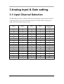
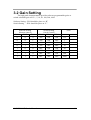
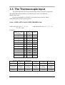
1
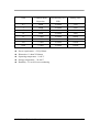
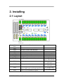
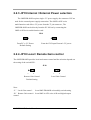
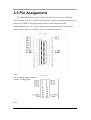
User’s Guide
Shop online at
www.omega.com
e-mail: [email protected]
OME-DB-889D
16-Channel Analog Multiplexer Board
OMEGAnet ® Online Service
www.omega.com
Internet e-mail
[email protected]
Servicing North America:
USA:
ISO 9001 Certified
Canada:
One Omega Drive, P.O. Box 4047
Stamford CT 06907-0047
TEL: (203) 359-1660
e-mail: [email protected]
976 Bergar
Laval (Quebec) H7L 5A1, Canada
TEL: (514) 856-6928
e-mail: [email protected]
FAX: (203) 359-7700
FAX: (514) 856-6886
For immediate technical or application assistance:
USA and Canada: Sales Service: 1-800-826-6342 / 1-800-TC-OMEGA®
Customer Service: 1-800-622-2378 / 1-800-622-BEST®
Engineering Service: 1-800-872-9436 / 1-800-USA-WHEN®
TELEX: 996404 EASYLINK: 62968934 CABLE: OMEGA
Mexico:
En Español: (001) 203-359-7803
FAX: (001) 203-359-7807
e-mail: [email protected]
[email protected]
Servicing Europe:
Benelux:
Postbus 8034, 1180 LA Amstelveen, The Netherlands
TEL: +31 (0)20 3472121
FAX: +31 (0)20 6434643
Toll Free in Benelux: 0800 0993344
e-mail: [email protected]
Czech Republic:
Frystatska 184, 733 01 Karviná, Czech Republic
TEL: +420 (0)59 6311899
FAX: +420 (0)59 6311114
Toll Free: 0800-1-66342
e-mail: [email protected]
France:
11, rue Jacques Cartier, 78280 Guyancourt, France
TEL: +33 (0)1 61 37 29 00
FAX: +33 (0)1 30 57 54 27
Toll Free in France: 0800 466 342
e-mail: [email protected]
Germany/Austria: Daimlerstrasse 26, D-75392 Deckenpfronn, Germany
TEL: +49 (0)7056 9398-0
Toll Free in Germany: 0800 639 7678
e-mail: [email protected]
United Kingdom:
ISO 9002 Certified
FAX: +49 (0)7056 9398-29
One Omega Drive, River Bend Technology Centre
Northbank, Irlam, Manchester
M44 5BD United Kingdom
TEL: +44 (0)161 777 6611
FAX: +44 (0)161 777 6622
Toll Free in United Kingdom: 0800-488-488
e-mail: [email protected]
It is the policy of OMEGA to comply with all worldwide safety and EMC/EMI regulations that
apply. OMEGA is constantly pursuing certification of its products to the European New Approach
Directives. OMEGA will add the CE mark to every appropriate device upon certification.
The information contained in this document is believed to be correct, but OMEGA Engineering, Inc. accepts
no liability for any errors it contains, and reserves the right to alter specifications without notice.
WARNING: These products are not designed for use in, and should not be used for, patient-connected applications.
OME-DB-889D MULTIPLEXER BOARD .........................................................................................2
1. FUNCTION DESCRIPTION ............................................................................................................2
1.1 FEATURES ........................................................................................................................................2
1.2 APPLICATIONS .................................................................................................................................2
1.3 SPECIFICATION.................................................................................................................................2
2. INSTALLING.....................................................................................................................................4
2.1 LAYOUT ...........................................................................................................................................4
2.2 JUMPER SETUP..................................................................................................................................5
2.2.1 JP0 ~ JP15 Analog Input R/C Filter ........................................................................................5
2.2.2 JP16 Analog Output Channel Jumper .....................................................................................5
2.2.3 JP19 Internal / External Power selection ................................................................................6
2.2.4 JP18 Local / Remote Gain control ........................................................................................6
2.3 PIN ASSIGNMENT .............................................................................................................................8
3 ANALOG INPUT & GAIN SETTING............................................................................................10
3.1 INPUT CHANNEL SELECTION ..........................................................................................................10
3.2 GAIN SETTING................................................................................................................................11
3.3. THE THERMOCOUPLE INPUT .........................................................................................................12
3.3.1 Voltage - TO - Temperature Conversion................................................................................13
3.3 CJC OUTPUT ..................................................................................................................................14
4 SIGNAL CONNECTION ..............................................................................................................15
4.1 FLOATING SIGNAL CONNECTION ...................................................................................................15
4.2 NON-FLOATING SIGNAL SOURCE ...................................................................................................16
4.3 CASCADING OME-DB-889D.........................................................................................................17
4.4 OPEN THERMOCOUPLE DETECTION................................................................................................18
4.5BLOCK DIAGRAM ...........................................................................................................................19
5 PROGRAMMING ............................................................................................................................20
5.1 USING OME-A-822PGL ...............................................................................................................20
5.3 EXAMPLE PROGRAM ......................................................................................................................21
6. CALIBRATION ...............................................................................................................................23
6.1 CALIBRATION VR DESCRIPTION ....................................................................................................23
6.2 CALIBRATION STEPS ......................................................................................................................23
OME-DB-889D User’s Manual
1
OME-DB-889D Multiplexer Board
1. Function Description
The OME-DB-889D is an expansion multiplexer / amplifier board for use with
OME-A-82X, OME-PCI-1800 series. Each OME-DB-889D multiplexes 16
differential analog input channels into one analog input of the DAS board. The high
grade instrumentation provides software programmable gains of 0.5, 1, 5, 10, 50, 100,
500 and 1000.
Thermocouple measurements are handled easily with OME-DB-889D. The
board includes cold junction sensing and compensation circuitry that provides a
scaling of 24.4mV/°C. Biasing restores are includes for open thermocouples
detentions of voltage measurements or 112 channels of thermocouple measurement.
1.1 Features
z
z
z
z
z
Connects directly to OME-A-82X, OME-PCI-1800 series boards with D-sub 37
connectors.
Cold-junction compensation for thermocouples and thermocouple open detection.
Software-programmable instrumentation amplifier
Gain of 0.5, 1, 5, 10, 50, 100, 500, 1000
Daisy chain up to ten OME-DB-889D boards
1.2 Applications
z
z
z
Energy management
Signal conditioning
Analog Multiplexer
1.3 Specification
z
z
z
z
z
Accepts thermocouple type : J, K, T, E, S, R, B
Cold-junction Compensation : +24.4mV/°C , 0V at 0°C
Overvoltage protection : ±30V Continuous
Common mode voltage : ±10V max.
Analog output Voltage to A/D card :±10V
OME-DB-889D User’s Manual
2
z
z
z
z
z
Gain
Common Mode
Rejection
Non linearity %of
FSR
Settling Time
0.5
99dB
±0.0004
23uS
1
99dB
±0.0004
23uS
5
114dB
±0.0004
28uS
10
99dB
±0.0004
28uS
50
123dB
±0.0004
140uS
100
123dB
±0.0004
140uS
500
123dB
±0.0008
1300uS
1000
123dB
±0.0008
1300uS
Power requirement : +5V@120mA
Dimension :114mm X 204mm
Operating temperature : 0~60°C
Storage temperature : -20~80°C
Humidity : 5% to 90% non condensing
OME-DB-889D User’s Manual
3
2. Installing
2.1 Layout
CJC Output
VR1
VR2
JP18
JP19
External
Voltage Input
Jumper /Connector
Name
CN1
CN2
CN3
CN4
CN5
CN6, CN8
CN7
JP0~JP15
JP16
JP17
JP18
JP19
Function
Connect to A/D connector of OME-A-82x series
Cascaded to another OME-DB-889D
Connect to D/O connector of OME-A-82x series
Cascaded to another OME-DB-889D
External +5V power input
Analog input channel 0~ channel 15
CJC signal output connector
Channel 0 ~ channel 15 R/C filter enable
Note
Select by JP19
Short : Filter Enable
Open : Filter Disable
Analog output channel selection
to OME-A-82x series
A/D card
CJC output channel selection
to OME-A-82x series
A/D card
Gain control by on board dip switch or digital
L : by dip switch
output of OME-A-82x series multi-function card R : by Digital output
Use PC’s +5V or External +5V power
OME-DB-889D User’s Manual
4
2.2 Jumper setup
2.2.1 JP0 ~ JP15 Analog Input R/C Filter
The OME-DB-889D provides R/C filter with each analog input channel by jumper
setting.
1.2KΩ
Channel 0 High
1uF 50V
Channel 0 Low
1.2KΩ
JP0~JP15
Short : with filter
Default setting
Open : Without filter
2.2.2 JP16 Analog Output Channel Jumper
The OME-DB-889D supports 10 separate jumper to select output channel, This
feature permits up to 10 OME-DB-889D’s be connected to a 10 channel analog input
card. Place the jumper in the output channel according to the channel of the analog
input card selected for that OME-DB-889D board. The following table illustrates the
jumper setting of using the OME-DB-889D with the OME-A-82X series.
JP16
JP17
X
Analog output CJC output
A/D CH0
A/D CH1
A/D CH2
A/D CH3
A/D CH4
A/D CH5
A/D CH6
A/D CH7
A/D CH8
A/D CH9
OME-DB-889D User’s Manual
X
0
1
2
3
4
5
6
7
8
9
If none of the output channel is used,
leave the jumper in position “X”. If
the CJC output is required for the
thermocouple applications, be aware
that the analog output and CJC output
share the connector for the analog
output and the CJC output.
Note: “X” means channels are not
supported by the OME-A-82Xseries
5
2.2.3 JP19 Internal / External Power selection
The OME-DB-889D requires single +5V power supply. the connector CN5 are
used for the external power supply connection. The OME-A-82X series
multi-function card offers +5V power from the 37 pin connector , The
OME-DB-889D can be directly from the PC I/O bus by connecting the
OME-A-82Xseries multi-function card.
JP19
From PC’s +5V Power
Default Setting
From the CN5 input External +5V power
2.2.4 JP18 Local / Remote Gain control
The OME-DB-889D provides local and remote control and the selection depends on
the setting of the switch SW1.
JP18
L
R
Remote Gain Control
Default Setting
L
R
Local Gain Control
Note:
“L” Local Gain control :
from OME-DB-889D on board dip switch setting
“R” Remote Gain control : from OME-A-82X series A/D card digital output
control
OME-DB-889D User’s Manual
6
Remote Gain Control
When the JP18 is set to “R”, it means Remote Gain Control is selected and the
gain is controlled by the digital signal of connector CN3 bit D4, D5, D6. The bit
pattern and related gain is illustrated as:
CN3
D6
D5
D4
Gain
0
0
0
0.5
0
0
1
1
0
1
0
5
0
1
1
10
1
0
0
50
1
0
1
100
1
1
0
500
1
1
1
1000
Local Gain Control
Sw1
1
2
3
4
Gain
ON
ON
ON
OFF
0.5
ON
ON
OFF
OFF
1
ON
OFF
ON
OFF
5
ON
OFF
OFF
OFF
10
OFF
ON
ON
OFF
50
OFF
ON
OFF
OFF
100
OFF
OFF
ON
OFF
500
OFF
OFF
OFF
OFF
1000
OME-DB-889D User’s Manual
7
2.3 Pin Assignment
The OME-DB-889D provides two 37pin D-Sub connector & two 20-pin flat
cable connector. The CN1, CN2 D-sub connector is analog output link to analog input
connector of OME-A-82X series multi-function card & cascaded another
OME-DB-889D. The CN3, CN4 is digital control multiplex & gain setting link to
digital output connector of OME-A-82x series multi-function card .
CN1 , CN2
Note:
AO_n : analog output channel n
A. GND : Analog ground
CN3 , CN4
Note
OME-DB-889D User’s Manual
8
DOn : DO0~DO3 Multiplexer control bit.
DO4~DO6 Gain control bit
D. GND : Digital Ground
+5V : PC’s +5V
OME-DB-889D User’s Manual
+12V PC’s +12V
9
3 Analog input & Gain setting
3.1 Input Channel Selection
The DB-990D provides 15 channel differential analog inputs. Input channel selection
is controlled by the 4 bit TTL/CMOS digital data (CN3 DO0~DO3) issued by the
OME-A-82x series multi-function card.
DO 3
DO 2
DO 1
DO 0
Analog input
channel
0
0
0
0
0
0
0
0
1
1
0
0
1
0
2
0
0
1
1
3
0
1
0
0
4
0
1
0
1
5
0
1
1
0
6
0
1
1
1
7
1
0
0
0
8
1
0
0
1
9
1
0
1
0
10
1
0
1
1
11
1
1
0
0
12
1
1
0
1
13
1
1
1
0
14
1
1
1
1
15
OME-DB-889D User’s Manual
10
3.2 Gain Setting
The high grade instrumentation provides software programmable gains or
switch selectable gain of 0.5 1, 5, 10, 50, 100, 500, 1000.
Software Setting : JP18 should be place on “R”
Switch Setting : JP18 should be place on “L”
Software Setting
(Remote control)
Switch Setting
(Local Control)
Gain
DO 6
DO 5
DO 4
SW1-3
SW1-2
SW1-1
0
0
0
ON
ON
ON
0.5
0
0
1
ON
ON
OFF
1
0
1
0
ON
OFF
ON
5
0
1
1
ON
OFF
OFF
10
1
0
0
OFF
ON
ON
50
1
0
1
OFF
ON
OFF
100
1
1
0
OFF
OFF
ON
500
1
1
1
OFF
OFF
OFF
1000
OME-DB-889D User’s Manual
11
3.3. The Thermocouple Input
The OME-DB-889D can accept thermocouple sensor to measure temperature.
The OME-DB-889D should be set to different gain value if use different
thermocouple type.
If you are usingOME-A-82XPGL series multi-function bard to linked
OME-DB-889D you have got the gain as:
Gain = OME-A-82X Gain X OME-DB-889D Gain
OME-A821PGL Gain = 1 , 2 , 4 , 8
50 , 100 , 1000
Examples
OME-DB-889D Gain = 0.5 , 1 , 5 , 10 ,
OME-A-82XPG
OME-DB
L Series
-889D
Gain
1
X
1
1
2
X
1
2
4
X
1
4
1
X
5
5
1
X
10
10
1
X
100
100
2
X
100
200
4
X
100
400
1
X
500
500
1
X
1000
1000
:
X
:
:
:
X
:
:
Thermocouple type & suitable gain
TYPE E
TYPE J
TYPE K
TYPE R
TYPE S
TYPE T
-270°C to 1000°C
-210°C to 760
-270°C to 1370°C
0°C to 1760°C
0°C to 1760°C
-270°C to 400°C
-9.835mV to
-8.096mV to
-6.458mV to
0mV to
0mV to
-6.258mV to
76.358mV
42.922mV
54.807mV
21.006mV
18.612mV
20.869mV
Gain=50
Gain=100
Gain=50
Gain=200
Gain=200
Gain=200
OME-DB-889D User’s Manual
12
3.3.1 Voltage - TO - Temperature Conversion
The temperature-versus-voltage relationship of a the thermocouple is not linear.
You can reference the thermocouple reference tables to get V to T values. Or
use temperature conversion equation to get V to T values.
Temperature Conversion Equation:
T = a0 + a1 x + a2 x^2 + a3 x^3 + a4 x^4 + …….. + an x^n
where
T = Temperature
x = Thermocouple Voltage
a = Polynomial coefficients unique to each thermocouple
n = Maximum order of the polynomial
TYPE E
TYPE J
a0 -100°C to 1000°C 0°C to 760°C
TYPE K
0°C to 1370°C
TYPE R
TYPE S
TYPE T
0°C to 1000°C 0°C to 1750°C -160°C to 400°C
a1
0.104967248
-0.048868252
0.226584602
0.263632917
0.927763167
0.100860910
a2
17189.45282
19873.14503
24152.10900
179075.491
169526.5150
25727.94369
a3
-282639.0850
-218614.5353
67233.4248
-48840341.37
-31568363.94
-767345.8295
a4
12695339.5
11569199.78
2210340.682
1.90002E+10
8990730663
78025595.81
a5
-448703084.6
-264917531.4
-860963914.9
-4.82704E+12
-1.63565E+12
-9247486589
a6
1.10866E+10
2018441314
4.835606E+10
7.62091E+14
1.88027E+14
6.97688E+11
a7
-1.76807E+11
-1.18452E+12
-7.20026E+16
-1.37241E+16
-2.66192E+13
a8
1.71842E+12
1.38690E+13
3.71496E+18
6.17501E+17
3.94078E+14
a9
-9.19278E+12
-6.33708E+13
-8.03104E+19
-1.56105E+19
2.06132E+13
1.69535E+20
Note:
1. The thermocouple range of this table is this equation limited.
2. Other detail data please reference thermocouple data book.
OME-DB-889D User’s Manual
13
3.3 CJC Output
The OME-DB-889D provides Cold-Junction Compensation (CJC) for the
thermocouple applications. If the CJC is required, place the JP17 in the position of the
channel to be used as a CJC reference. If the CJC is not required, Place the JP17 in
the position “X”.
CJC has output on connector CN7. Using a voltage meter measures CN7 which exists
a voltage related to the OME-DB-889D board temperature. The CJC voltage transfers
to temperature with formula:
T(°C) = V*1000/24.4
CN7
A.GND
V: Voltage of CN7
T: Temperature of OME-DB-889D
Voltage meter
CJC output
+
-
Example: (Turbo C)
Multi-Function Card: OME-A-822PGL
The OME-DB-889D JP17 placed on “7”.
/*====================Example Program ===================*/
#include <stdio.h>
#include “A822.h>
main(void)
{int ad_channel , gain , trigger_mode, poll_data ;
float temp;
A822_Initialize(0,0x220, -1, -1);
/* Initials OME-A-822PGL Ref. OME-A-822PGH/L Software
Manual */
ad_channel=7;
gain=0;
trigger_mode=1;
for(;;)
{
A822_AD_SetChGainMode(ad_channel , gain , trigger_mode );
/* SettingOME-A-822 A/D channel =7 , Gain=1 , Trigger mode = Software
trigger */
poll_data=A822_AD_PollingVar();
temp=(float)(((poll_data-2048)*5/2048)*1000/24.4);
prinf(“ Temperature = %4.1f °C \n”, temp);
}
}
OME-DB-889D User’s Manual
14
4 Signal Connection
The OME-DB-889D can multiplex up to 16 channel differential inputs. Input channel
selection is controlled by a CN3 D4~ D6 digital output by OME-A-82x series
multi-function card.
4.1 Floating Signal Connection
The OME-DB-889D has only differential input channels, each input channel
should be two signal wires. The input should be connected as:
CH0HI
Floating Signal Source
OME-DB-889
D
CH0LO
Differential signal input
OME-DB-889D User’s Manual
A.GND
15
4.2 Non-Floating Signal Source
Some the signal source has one side connect to a local ground. The signal ground with
OME-DB-889D ground will not be same voltage level. The input should be show as:
CH0HI
Common mode Signal Source
OME-DB-889D
CH0LO
A.GND
Common mode signal input
OME-DB-889D User’s Manual
16
4.3 Cascading OME-DB-889D
OME-A-82X series A/D card
20 Pin Flat Cable
1.
A821PGH/L
2.
OME-A-822PGH/L
3.
OME-A-823PGH/L
OME-DB-889D #2
4.
OME-A-826PGH/L
5.
PCI-1800PGH/L
Note: PCI-1802 should be via DB-1825
connect to OME-DB-889D
OME-A-82X
OME-DB-889D
JP16
A/D Channel 0
OME-DB-889D #1
0
A/D Channel 1
OME-DB-889D #2
1
A/D Channel 2
OME-DB-889D #3
2
A/D Channel 3
OME-DB-889D #4
3
A/D Channel n OME-DB-889D #n
n
A/D Channel 9 OME-DB-889D #10
9
OME-DB-889D #3
series
OME-DB-889D #n
Up to 10 Boards
Note: Each OME-DB-889D JP17 place on “X”
OME-DB-889D User’s Manual
17
4.4 Open Thermocouple Detection
The OME-DB-889D provides open thermocouple detection through a resistor
circuitry. These resisters are normally not connected. The user can find on the back of
the board has two solder gaps for each input channel. If you short the solder gaps, the
open thermocouple detection is enabled.
HJ0
100MΩ
-15V
1.2KΩ
Channel 0 High
1uF 50V
Channel 0 Low
1.2KΩ
OME-DB-889
37Pin Cable
GND
LJ0
10KΩ
Note:
If a thermocouple opens, the bias resistor will slowly pull the input voltage to
-10V then user can use a simple application program to detect the voltage
change.
OME-DB-889D User’s Manual
18
4.5 Block Diagram
CN1
CN2
CN8 Connector with R/C filter
JP16 JP17
OME-A-82X
AMP
Analog input
16 channel Multiplexer
VR1
CJC
Dip Switch
OME-A-82X
CN3
CN4
Control
Logic
VR2
D/O control signal
CN6 Connector with R/C filter
OME-DB-889D Block Diagram
CN1: connect to OME-A-82x series multi-function card
CN2: connect to CN1 of another OME-DB-889D
CN3: connect to OME-A-82x series digital output
CN4: connect to CN3 of another OME-DB-889D
AMP: programmable gain amplifier (PGA)
VR1: PGA off-set adjustment.
VR2: CJC gain adjustment
OME-DB-889D User’s Manual
19
5 Programming
The OME-A-82x series multi-function card can support up to 160 channels by
cascading 10 OME-DB-889D’s without complex programming.
5.1 Using OME-A-822PGL
This section will use OME-A-822PGL to link OME-DB-889D.
The major steps are listed below:
Step 1: Hardware installing.
1.
Turn off power of computer.
2.
Plug in OME-A-822PGL then connect 37 pin cable & 20 pin flat cables to CN1
and CN3 of OME-DB-889D.
3.
Setup OME-DB-889D (Ref. Jumper setting section of OME-DB-889D. The
example program uses default setup )
4.
Connect your signal wiring.
5.
Turn on your computer power.
6.
Installing OME-A-822PGL C library.
7.
Now you are ready to programming.
Step 2: Software programming (C Language)
1.
Using OME-A-822 library function to initial OME-A-822PGL
2.
Setup OME-A-822PGL: Bipolar mode , Gain = 1 , Analog input channel = 0 ,
Trigger mode = Polling mode.
3.
Send digital output of OME-A-822PGL data to control OME-DB-889D
D0~D3: OME-DB-889D channel selection, D4~D6: OME-DB-889D Gain setting
4.
Reading OME-A-822PGL analog input data
5.
Conversion data to voltage or temperature
Note:
The OME-A-82X series programming steps are same as those for the
OME-A-822PGL
OME-DB-889D User’s Manual
20
5.3 Example Program
DEMO_01.C
/* ============== Using OME-A-822 / connect one OME-DB-889D
=================*/
#include <stdio.h>
#include “A822.h”
main(void)
{int data1,data2;
float vol1,vol2;
A822_Initialize(0,0x220,-1,-1);
/* OME-A-822 Base address in 0x220 ref. OME-A-822 Software manual */
for(;;)
{
/*===============reading OME-DB-889D Channel 0 , Gain =1
=============*/
A822_AD_SetChGainMode(0,0,1);
/* Setup OME-A-822 A/D channel 0, Gain = 1 , Polling mode
*/
A822_DO(0x0010);
/* Send D/O data to OME-DB-889D , Channel 0, Gain=1 */
delay(10);
/* delay about 43u sec . Ref. Page 3 Settling time */
data1=A822_AD_PollingVar();
/* Reading OME-A-822 A/D data */
vol1=(float)((data1-2048)*5/2048);
printf(“OME-DB-889D channel 0= %6.4f V\n”,vol1);
/*===========reading OME-DB-889D Channel 1 , Gain=10
===============*/
A822_AD_SetChGainMode(0,0,1);
/* Setup OME-A-822 A/D channel 0, Gain = 1 , Polling mode
*/
OME-DB-889D User’s Manual
21
A822_DO(0x0021);
/* Send D/O data to OME-DB-889D , Channel 1, Gain=10 */
delay(10);
/* delay about 43u sec , Ref. Page 3 Setting time*/
data2=A822_AD_PollingVar();
/* Reading OME-A-822 A/D data */
vol2=(float)((data2-2048)*0.5/2048);
printf(“OME-DB-889D channel 1= %6.4f V\n”,vol2);
}
}
OME-DB-889D User’s Manual
22
6. Calibration
The OME-DB-889D is calibrated to its best of operation. For environment subjected
to large vibrations, recalibration is recommended. Before calibrating the
OME-DB-889D, user should consider having the following available:
z
z
z
One 6 digital voltage meter
One temperature meter
One OME-A-82x series multifunction card
6.1 Calibration VR Description
There are two VRs on the OME-DB-889D.
VR Num.
Description
VR1
Amplifier Offset adjustment
VR2
CJC Gain adjustment
6.2 Calibration Steps
1.
2.
3.
4.
5.
6.
7.
8.
9.
10.
11.
Turn off computer power.
Connect OME-A-822PGL (Or any OME-A-82x series multi-function card) to
OME-DB-889D.
Setup OME-DB-889D to default setting
Short CH0HI to CH0LO to A.GND of DB889D.
Connect probe of voltage meter to CN7 (CJC output: + , A.GND : - ).
Turn on computer power
Wait about 5 minute (warn up).
Run Calibration program of OME-DB-889D.
Close the probe of temperature meter to OME-DB-889D them reading
temperature value.
Adjust VR1 until the screen value = 0;
Adjust VR2 until voltage meter reading value = temperature value X 2.44mV
OME-DB-889D User’s Manual
23
WARRANTY/DISCLAIMER
OMEGA ENGINEERING, INC. warrants this unit to be free of defects in materials and workmanship for a
period of 13 months from date of purchase. OMEGA’s WARRANTY adds an additional one (1) month
grace period to the normal one (1) year product warranty to cover handling and shipping time. This
ensures that OMEGA’s customers receive maximum coverage on each product.
If the unit malfunctions, it must be returned to the factory for evaluation. OMEGA’s Customer Service
Department will issue an Authorized Return (AR) number immediately upon phone or written request.
Upon examination by OMEGA, if the unit is found to be defective, it will be repaired or replaced at no
charge. OMEGA’s WARRANTY does not apply to defects resulting from any action of the purchaser,
including but not limited to mishandling, improper interfacing, operation outside of design limits,
improper repair, or unauthorized modification. This WARRANTY is VOID if the unit shows evidence of
having been tampered with or shows evidence of having been damaged as a result of excessive corrosion;
or current, heat, moisture or vibration; improper specification; misapplication; misuse or other operating
conditions outside of OMEGA’s control. Components which wear are not warranted, including but not
limited to contact points, fuses, and triacs.
OMEGA is pleased to offer suggestions on the use of its various products. However,
OMEGA neither assumes responsibility for any omissions or errors nor assumes liability for any
damages that result from the use of its products in accordance with information provided by
OMEGA, either verbal or written. OMEGA warrants only that the parts manufactured by it will be
as specified and free of defects. OMEGA MAKES NO OTHER WARRANTIES OR
REPRESENTATIONS OF ANY KIND WHATSOEVER, EXPRESS OR IMPLIED, EXCEPT THAT OF TITLE,
AND ALL IMPLIED WARRANTIES INCLUDING ANY WARRANTY OF MERCHANTABILITY AND
FITNESS FOR A PARTICULAR PURPOSE ARE HEREBY DISCLAIMED. LIMITATION OF
LIABILITY: The remedies of purchaser set forth herein are exclusive, and the total liability of
OMEGA with respect to this order, whether based on contract, warranty, negligence,
indemnification, strict liability or otherwise, shall not exceed the purchase price of the
component upon which liability is based. In no event shall OMEGA be liable for
consequential, incidental or special damages.
CONDITIONS: Equipment sold by OMEGA is not intended to be used, nor shall it be used: (1) as a “Basic
Component” under 10 CFR 21 (NRC), used in or with any nuclear installation or activity; or (2) in medical
applications or used on humans. Should any Product(s) be used in or with any nuclear installation or
activity, medical application, used on humans, or misused in any way, OMEGA assumes no responsibility
as set forth in our basic WARRANTY/ DISCLAIMER language, and, additionally, purchaser will indemnify
OMEGA and hold OMEGA harmless from any liability or damage whatsoever arising out of the use of the
Product(s) in such a manner.
RETURN REQUESTS/INQUIRIES
Direct all warranty and repair requests/inquiries to the OMEGA Customer Service Department. BEFORE
RETURNING ANY PRODUCT(S) TO OMEGA, PURCHASER MUST OBTAIN AN AUTHORIZED RETURN
(AR) NUMBER FROM OMEGA’S CUSTOMER SERVICE DEPARTMENT (IN ORDER TO AVOID
PROCESSING DELAYS). The assigned AR number should then be marked on the outside of the return
package and on any correspondence.
The purchaser is responsible for shipping charges, freight, insurance and proper packaging to prevent
breakage in transit.
FOR WARRANTY RETURNS, please have the
following information available BEFORE
contacting OMEGA:
1. Purchase Order number under which the product
was PURCHASED,
2. Model and serial number of the product under
warranty, and
3. Repair instructions and/or specific problems
relative to the product.
FOR NON-WARRANTY REPAIRS, consult OMEGA
for current repair charges. Have the following
information available BEFORE contacting OMEGA:
1. Purchase Order number to cover the COST
of the repair,
2. Model and serial number of the product, and
3. Repair instructions and/or specific problems
relative to the product.
OMEGA’s policy is to make running changes, not model changes, whenever an improvement is possible. This affords
our customers the latest in technology and engineering.
OMEGA is a registered trademark of OMEGA ENGINEERING, INC.
© Copyright 2002 OMEGA ENGINEERING, INC. All rights reserved. This document may not be copied, photocopied,
reproduced, translated, or reduced to any electronic medium or machine-readable form, in whole or in part, without the
prior written consent of OMEGA ENGINEERING, INC.
Where Do I Find Everything I Need for
Process Measurement and Control?
OMEGA…Of Course!
Shop online at www.omega.com
TEMPERATURE
Thermocouple, RTD & Thermistor Probes, Connectors, Panels & Assemblies
Wire: Thermocouple, RTD & Thermistor
Calibrators & Ice Point References
Recorders, Controllers & Process Monitors
Infrared Pyrometers
PRESSURE, STRAIN AND FORCE
Transducers & Strain Gages
Load Cells & Pressure Gages
Displacement Transducers
Instrumentation & Accessories
FLOW/LEVEL
Rotameters, Gas Mass Flowmeters & Flow Computers
Air Velocity Indicators
Turbine/Paddlewheel Systems
Totalizers & Batch Controllers
pH/CONDUCTIVITY
pH Electrodes, Testers & Accessories
Benchtop/Laboratory Meters
Controllers, Calibrators, Simulators & Pumps
Industrial pH & Conductivity Equipment
DATA ACQUISITION
Data Acquisition & Engineering Software
Communications-Based Acquisition Systems
Plug-in Cards for Apple, IBM & Compatibles
Datalogging Systems
Recorders, Printers & Plotters
HEATERS
Heating Cable
Cartridge & Strip Heaters
Immersion & Band Heaters
Flexible Heaters
Laboratory Heaters
ENVIRONMENTAL
MONITORING AND CONTROL
Metering & Control Instrumentation
Refractometers
Pumps & Tubing
Air, Soil & Water Monitors
Industrial Water & Wastewater Treatment
pH, Conductivity & Dissolved Oxygen Instruments
M4019/1103