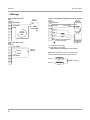
1
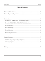
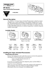
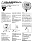
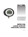
User’s Guide
http://www.omega.com
e-mail: [email protected]
DPG10L
LARGE DISPLAY
PRESSURE GAUGE
M3367/0606
Where Do I Find Everything I Need for
Process Measurement and Control?
OMEGA...Of Course!
TEMPERATURE
✓ Thermocouple, RTD & Thermistor
Probes, Connectors, Panels &
Assemblies
✓ Wire: Thermocouple, RTD &
Thermistor
✓ Calibrators & Ice Point References
✓ Recorders, Controllers & Process
Monitors
✓ Infrared Pyrometers
PRESSURE,
STRAIN AND FORCE
✓ Transducers & Strain Gages
✓ Load Cells & Pressure Gages
✓ Displacement Transducers
✓ Instrumentation & Accessories
FLOW/LEVEL
✓ Rotameters, Gas Mass Flowmeters
& Flow Computers
✓ Air Velocity Indicators
✓ Turbine/Paddlewheel Systems
✓ Totalizers & Batch Controllers
pH/CONDUCTIVITY
✓ pH Electrodes, Testers &
Accessories
✓ Benchtop/Laboratory Meters
✓ Controllers, Calibrators,
Simulators & Pumps
✓ Industrial pH & Conductivity
Equipment
DATA ACQUISITION
✓ Data Acquisition & Engineering
Software
✓ Communications-Based
Acquisition Systems
✓ Plug-in Cards for Apple, IBM &
Compatibles
✓ Datalogging Systems
✓ Recorders, Printers & Plotters
HEATERS
✓ Heating Cable
✓ Cartridge & Strip Heaters
✓ Immersion & Band Heaters
✓ Flexible Heaters
✓ Laboratory Heaters
ENVIRONMENTAL
MONITORING AND CONTROL
✓ Metering & Control
Instrumentation
✓ Refractometers
✓ Pumps & Tubing
✓ Air, Soil & Water Monitors
✓ Industrial Water & Wastewater
Treatment
✓ pH, Conductivity & Dissolved
Oxygen Instruments
M3367/0606
DPG10L
Table of Contents
Warranty/Disclaimer.........................................................................2
Return Requests/Inquiries.................................................................3
Instructions.......................................................................................4
To Zero or “TARE OUT” an existing offset...................................4
To select PEAK HI or PEAK LO hold functions............................4
To set Alarms..................................................................................5
Zero Trimming................................................................................6
Re-calibration................................................................................6
Battery Replacement......................................................................6
Output Options..................................................................................7
0-2 V Analog Output Signal Option...............................................7
Alarm(s) Option.............................................................................7
Wiring................................................................................................8
DPG10L
M3367/0606
•Warranty/Disclaimer
OMEGA ENGINEERING, INC. warrants this unit to be free of defects in materials
and workmanship for a period of 13 months from date of purchase. OMEGA’s Warranty
adds an additional one (1) month grace period to the normal one (1) year product
warranty to cover handling and shipping time. This ensures that OMEGA’s customers
receive maximum coverage on each product.
If the unit malfunctions, it must be returned to the factory for evaluation. OMEGA’s
Customer Service Department will issue an Authorized Return (AR) number immediately
upon phone or written request. Upon examination by OMEGA, if the unit is found to be
defective, it will be repaired or replaced at no charge. OMEGA’s WARRANTY does not
apply to defects resulting from any action of the purchaser, including but not limited to
mishandling, improper interfacing, operation outside of design limits, improper repair,
or unauthorized modification. This WARRANTY is VOID if the unit shows evidence
of having been tampered with or shows evidence of having been damaged as a result
of excessive corrosion; or current, heat, moisture or vibration; improper specification;
misapplication; misuse or other operating conditions outside of OMEGA’s control.
Components which wear are not warranted, including but not limited contact points,
fuses, and triacs.
OMEGA is please to offer suggestions on the use of its various products. However,
OMEGA neither assumes responsibility for any omissions or errors nor assumes
liability for any damages that result from the use of its products in accordance with
information provided by OMEGA, either verbal or written. OMEGA warrants
only that the parts manufactured by it will be as specified and free of defects.
OMEGA MAKES NO OTHER WARRANTIES OR REPRESENTATIONS OF
ANY KIND WHATSOEVER, EXPRESS OR IMPLIED, EXCEPT THAT OF
TITLE, AND ALL IMPLIED WARRANTIES INCLUDING ANY WARRANTY
OF MERCHANTABILITY AND FITNESS FOR A PARTICULAR PURPOSE
ARE HEREBY DISCLAIMED. LIMITATION OF LIABILITY: The remedies
of purchaser set forth herein are exclusive, and the total liability of OMEGA
with respect to this order, whether based on contract, warranty, negligence,
indemnification, strict liability or otherwise, shall not exceed the purchase price of
the component upon which liability is based. In no even shall OMEGA be liable for
consequential, incidental or special damages.
CONDITIONS: Equipment sold by OMEGA is not intended to be used, nor shall it be
used: (1) as a “Basic Component” under 10 CFR 21 (NRC), used in or with any nuclear
installation or activity; or (2) in medical applications or used on humans. Should any
Product(s) be used in or with any nuclear installation or activity, medical application,
used on humans, or misused in any way, OMEGA assumes no responsibility as set forth
in our basic WARRANTY/DISCLAIMER language, and, additionally, purchaser will
indemnify OMEGA and hold OMEGA harmless from any liability or damage whatsoever
arising out of the use of the Product(s) in such a manner.
M3367/0606
DPG10L
•Return Requests/Inquiries
Direct all warranty and repair requests/inquiries to the OMEGA Customer
Service Department. BEFORE RETURNING ANY PRODUCT(S) TO
OMEGA, PURCHASER MUST OBTAIN AN AUTHORIZED RETURN
(AR) NUMBER FROM OMEGA’S CUSTOMER SERVICE DEPARTMENT
(IN ORDER TO AVOID PROCESSING DELAYS). The assigned AR number
should then be marked on the outside of the return package and on any
correspondence.
The purchaser is responsible for shipping charges, freight, insurance and
proper packaging to prevent breakage in transit.
Warranty Returns
For WARRANTY RETURNS, please have the following information
available BEFORE contacting OMEGA:
1. Purchase Order number under which the product was PURCHASED,
2. Model and serial number of the product under warranty, and
3. Repair instructions and/or specific problem relative to the product.
Non-Warranty Repairs
For NON-WARRANTY REPAIRS, consult OMEGA for current repair
charges. Have the following information available BEFORE contact OMEGA:
1. Purchase Order number to cover the COST of the repair,
2. Model and serial number of the product, and
3. Repair instructions and/or specific problem relative to the product.
DPG10L
M3367/0606
•Instructions
The model DPG10L Digital Pressure Gauge has several features not normally
found as standard in Digital Pressure Gauges. These include the Analog Scale,
Tare, and Peak Holds. The Analog Scale is a 40 segment display that appears
around the edge of the liquid crystal display. This scale represents the pressure
reading as a percentage of full scale, and each individual segment equals 2.5%.
The Tare feature provides a method of zeroing out an existing offset such as the
weight of the platform on a hydraulic scale. The Hold feature allows the user to
select Hi or Lo. When the Hold is enabled the reading displayed is the highest
or lowest pressure experienced in the system since Hold was enabled, and this
information will continue to be updated at the rate of six times a second until
Hold is disabled.
1.0 To Zero or “TARE OUT” an existing offset
1.1 Press and hold the “MODE” key until the reading starts flashing. Release
“MODE” key.
1.2 Press “ENTR” key until the reading becomes 0000.
NOTE: Tare range is 100% of Full Scale.
1.3 To return to the Gross reading press and hold “ENTR”, then with
“ENTR” still depressed press “MODE” until the reading returns to the
gross, then release both keys.
2.0 To select PEAK HI or PEAK LO hold functions
2.1 Press and hold the “MODE” key until the reading starts flashing. Release
the “MODE” key, then press “MODE” key once more, the display will
read “HOLD”. Press “ENTR” key once, the display will read “NO H”.
Using “up” or “down” keys select “NO H” (no Hold), “H Lo” (Peak
Low Hold), or “H Hi” (Peak High Hold). Press “ENTR” key to lock your
selection.
NOTE: When the Hold function is enabled “PEAK” is displayed, this will
be the same for “Hi” or “Lo” Hold. You must remember which you have
engaged.
2.2 To reset after capturing a Hi Peak or Lo Peak, Press and hold “MODE”
key until the reading starts flashing. Release the “MODE” key, then press
“ENTR”, hold momentarily then release.
M3367/0606
2.3
DPG10L
To disengage Hold press and hold the “MODE” key until the reading
starts flashing. Release the “MODE” key then press the “MODE” key
once more, the display will read “HOLD”. Press the “ENTR” key, the
display will read “NO H” Press the “ENTR” key once more and the
display will return to reading the system pressure.
3.0 To Set Alarms
3.1 Press and hold the “MODE” key until the reading starts flashing, then
Press the “MODE” key twice more. The display will read “AL 1”. Press
the “ENTR” key to display the alarm setting. Pressing the “ENTR” key
again will set the alarm and return the display to the normal mode. If the
alarm setting is to be changed, the “up” and “down” keys can be used to
increase or decrease the setting one count at a time, Pressing the “MODE”
key and holding it down while Pressing “up” or “down” momentarily will
change 10 counts for each key operation. If the “MODE” key and “up” or
“down” are held down simultaneously, the setting will ‘FREE RUN’ until
the key is released.
NOTE: While setting the alarm, only one segment of the analog scale is
displayed and it corresponds to the % full scale of the alarm setting.
3.2 When the desired alarm setting is displayed, Press “ENTR” to set and
return to normal mode.
3.3 To set alarm 2: Press and hold the “MODE” key until the reading starts
flashing, then Press the “MODE” key three more times. The display will
read “AL 2”. Press “ENTR” key to display the alarm setting. Pressing
the “ENTR” key again will set the alarm and return the display to the
normal mode. If the alarm setting is to be changed, the “up” and “down”
keys can be used to increase or decrease the setting one count at a time,
Pressing the “MODE” key and holding it down while Pressing “up” or
“down” momentarily will change 10 counts for each key operation. If
the “MODE” key and “up” or “down” are held down simultaneously, the
setting will ‘FREE RUN’ until the key is released.
NOTE: While setting the alarm, only one segment of the analog scale is
displayed and it corresponds to the % full scale of the alarm setting.
3.4 When the desired alarm setting is displayed, Press “ENTR” to set and
return to normal mode.
DPG10L
3.5
M3367/0606
The alarm set point indicator segment of the bar graph will “blink” when
that set point is activated. The hookup of optional outputs is covered later
in this manual
4.0 Zero Trimming
4.1 Should it be necessary to readjust the Zero setting, an adjustment has
been provided. Prior to adjusting the zero, verify that you are displaying
the “gross” zero reading by performing step 1.3. On the back of the case,
in the upper left, there are two cover screws labeled “Z” and “S”. Remove
the screw covering the “Z” and utilizing a jewelers screwdriver, turn the
small screw to re-zero the unit. The ideal zero is indicated by a reading of
0000 with an intermittently flashing “-” sign.
NOTE: Do not readjust the “S” as this will invalidate the factory
calibration.
5.0 Re-calibration
This procedure requires a known pressure source of at least ± 0.1% accuracy
in order to fully utilize the potential of the DPG10L (If not available, the gauge
may be returned to OMEGA for re-certification)
5.1 With 0 psig applied (port vented) adjust zero per instructions of 4.0.
5.2 Apply full scale pressure to the pressure port and adjust the “S” until the
display reads the correct pressure.
5.3 Re-check zero and re-adjust the zero if required.
5.4 Repeat steps 5.2 and 5.3 until no further adjustment is required.
6.0 Battery Replacement
6.1 To access the battery, the unit must be partially disassembled. Remove
the thread ring surrounding the lens by turning counter clockwise. Carefully
turn the unit face down with one hand prepared to “catch” the lens and
display board as they fall from the housing. Do not allow the display board
to fall more than an inch or two as there are wires connecting it to the main
housing.
6.2 Disconnect the two wire connector that leads from the batteries to the
electronic. Then remove the battery or batteries from the holder(s) and
replace with the same type that was removed, taking care to observe the
correct polarity. Re-connect the battery connector.
M3367/0606
DPG10L
•DPG10L Output Options
Several output signals are available on the circular 6 pin connector located on
the rear of the unit. Depending on the option selected the signals are present on
pins as follows.
DPG10L
Out Table
PG-10000 Pin Pin
Out Table
A
B
C
D
E
F
4-20 mA
0-2 VDC
with Alarm 4-20 mA
0-5 VDC with Alarm
+ Excitation + Excitation + Excitation
N/C
– Excitation – Excitation
+ Output
+ Output
Dig Gnd
– Output
N/C
– Output
Alarm 2
– Excitation
N/C
Alarm 2
Alarm 1
N/C
N/C
Alarm 1
Gnd
Gnd
N/C
Gnd
0-2 VDC
N/C
+ Output
– Output
N/C
N/C
N/C
0-5 VDC
Ex Pwr
with Alarm
+ Pwr
+ Excitation
– Pwr (Com) + Output
N/C
– Out/– Ex
N/C
Alarm 2
N/C
Alarm 1
N/C
Dig Gnd
N/C indicates no connection.
1. 0-2 V Analog Output Signal Option
The analog output signal is available on pins B and C of the circular 6 pin
connector located on the rear of the unit. The signal is short circuit protected and
capable of driving low impedance external loads with fixed gain to a specified
output level, with 10K Ohm and above loads. Frequency response is a function
of the pressure range, generally 1 to 3 KHZ. Loading of the analog output will
result in a reduction of the battery life expectancy due to the additional current
through the external load.
2. Alarm(s) Option
The two open drain alarm output signals are present on pin D (alarm 2) and
pin E (alarm 1) of the output connector. The alarm trip-points are software
selected by using the unit’s front key-pad (see section 3.0 in the instructions
section of this manual). When active, they are capable of sinking 500 mA at 60
VDC Max with 7.5 ohms typical ON resistance to the digital ground as if they
were two independent SPST normally closed switches with one end connected
to the digital ground and the other end presented as an output. The typical
configuration will require an external power supply and a 1 to 10K Ohm pull up
resistor connected between the positive terminal of the power source and each
alarm output. Inductive load switching such as small solenoids or relays is also
possible utilizing the alarm output as a “low side switch”. The use of a diode or
a capacitor across the load terminals is required to reduce “kick-backs”.
DPG10L
M3367/0606
•Wiring
Typical 4-20 mA Circuit
Process
Controller
Gauge
Connector
+ EXCITATION
A
B
+Vin
– EXCITATION
Gauge
Connector
A
RL
B
C
C
D
Typical 4-20 mA Circuit with Open Collector Alarms
4-20 mA
CURRENT
LOOP
D
E
E
F
F
+Excitation
-Excitation
B
+ OUTPUT
C
– OUTPUT
D
– EXCITATION
+
SUPPLY
VOLTAGE
4-20mA Loop
+Vin
RL
Dig Gnd
Alarm 2
Alarm 1
Gnd
Typical 0-5 VDC Circuit
Gauge
Connector
+ EXCITATION
A
Process
Controller
Alarm
Loads
DC* Power
Supply
+
(Optional but recommended
for surge protection)
*Any voltage up
to 60 VDC @
160 mA max.
R L = 250 ohm for 1-5 V output
R L = 500 ohm for 2-10 V output
DO NOT EXCEED 750 OHMS WITH 24 VDC SUPPLY.
NOTE: Alarm loads may be relay coils as shown below.
Connect 1 A 400 V diodes to protect from relay "kick".
Alarm 2
E
F
To + Power
Alarm 1
Thank You for Purchasing
OMEGA Products
OMEGA’s policy is to make running changes, not model changes, whenever
an improvement is possible. This affords our customers the latest in
technology and engineering.
It is the policy of OMEGA to comply with all worldwide safety and EMC/
EMI regulations that apply. OMEGA is constantly pursuing certification of
its products to the European New Approach Directives. OMEGA will add
the CE mark to every appropriate device upon certification.
The information contained in this document is believed to be correct, but
OMEGA Engineering, Inc. accepts no liability for any errors it contains, and
reserves the right to alter specifications without notice.
WARNING: These products are not designed for use in, and should not be
used for, patient-connected applications.
Again, thank you for your interest in OMEGA.
We welcome the opportunity to help you achieve your application goals.
OMEGAnet® On-Line Service
www.omega.com
Internet e-mail
[email protected]
Servicing North America:
USA:
One Omega Drive, P.O. Box 4047
Stamford, CT 06907-0047
TEL: (203) 359-1660
e-mail: [email protected]
Canada:
976 Bergar
Laval (Quebec) H7L 5A1
TEL: (514) 856-6928
e-mail: [email protected]
ISO 9001 Certified
FAX: (203) 359-7700
FAX: (514) 856-6886
For immediate technical or application assistance:
USA and Canada:Sales Service: 1-800-826-6342 / 1-800-TC-OMEGA®
Customer Service: 1-800-622-2378 / 1-800-622-BEST®
Engineering Service: 1-800-872-9436 / 1-800-USA-WHEN®
TELEX: 996404 EASYLINK: 62968934 CABLE: OMEGA
Mexica:
Tel: (001) 800-826-6342
En Español: (001) 203-359-7803
FAX: (001) 203-359-7807
e-mail: [email protected]
[email protected]
Servicing Europe:
Benelux:
Postbus 8034, 1180 LA Amstelveen, The Netherlands
TEL: +31 (0) 20 6418405
FAX: +31 (0) 20 6434643
Toll Free in Benelux: 0800 0993344
e-mail: [email protected]
Czech Republic: Rudé armády 1868, 733 01 Karviná
TEL: +420 (0) 69 6311899
FAX: +420 (0) 69 6311114
Toll Free in Czech Rep.: 0800-1-66342 e-mail: [email protected]
France:
9, rue Denis Papin, 78190 Trappes
TEL: +33 (0) 130 621400
Toll Free in France: 0800-4-06342
e-mail: [email protected]
FAX: +33 (0) 130 699120
Germany/Austria:Daimlerstrasse 26, D-75392 Deckenpfronn, Germany
TEL: +49 (0) 7056 3017
FAX: +49 (0) 7056 8540
Toll Free in Germany: 0800 TC-OMEGASM
e-mail: [email protected]
United Kingdom:
ISO 9002 Certified
One Omega Drive, River Bend Technology Centre
Northbank, Irlam, Manchester
M44 5EX, United Kingdom
TEL: +44 (0) 161 777 6611
FAX: +44 (0) 161 777 6622
Toll Free in the United Kingdom: 0800 488 488
e-mail: [email protected]
OMEGA is a registered trademark of OMEGA ENGINEERING, INC.
© Copyright 2005 OMEGA ENGINEERING, INC. All rights reserved. This document may not be copied,
photocopied, reproduced, translated, or reduced to any electronic medium or machine-readable form, in whole or in
part, without the prior written consent of OMEGA ENGINEERING, INC.