1
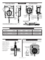
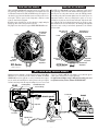
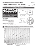
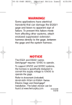
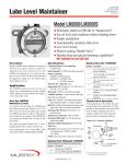
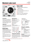
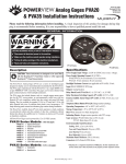
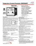
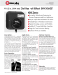
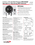
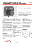
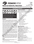
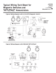
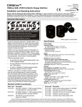
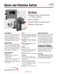
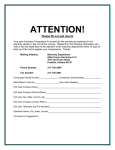
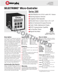
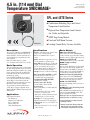
4.5 in. (114 mm) Dial
Temperature SWICHGAGE®
SPL/45-94117B
Revised 08-05
Catalog Section 10
SPL and 45TE Series
*
**
45TE Model
■
Combination Indicating Gage and Critical
Temperature Limit Switches
■
High and Low Temperature Limit Contacts
Are Visible and Adjustable
■
SPDT Snap-Acting Models
■
Panel and Wall Mount Versions
■
Latching Control Relay Versions Available
Description
Specifications
Basic Models
The 4-1/2 in. (114 mm) dial size SWICHGAGE® is
a mechanical gage for temperature indication. It
includes adjustable, electrical contacts that can be
used for start and stop, to trip alarms and to shut
down equipment.
Ranges are available from 15° to 250°F
(9° to 121°C) thru 260° to 450°F (127° to 232°C).
Dial: White on black, dual scale, °F and °C standard, 4-1/2 in. (114 mm) diameter.
Case: Die cast aluminum, surface or panel
mount.
Capillary: PVC armored copper tube, 5 ft. long
(1.5 m.) standard–see options next page.
Sensing Bulb: Copper bulb: 1/2 in. (13 mm) OD;
Length: 7 in. (178 mm). Minimum bulb insertion–see corresponding chart, on page 2.
Pressure Rating: 600 psi (4.1 MPa) [41 bar].
Connection: 1/2 NPT compression fitting.
Overrange: Do not exceed 10% above full range.
Limit Contacts (SPLC and SPLFC): 1-SPDT,
Center off; pilot-duty; 2 A @ 30 V; 1 A @
125 VAC. Contacts are gold plated silver.
Snap-Acting Switches (45TE and 45TEF):
2-SPDT; 2 A @ 250 VAC.
Dry Relay Contact (“BP” Models):
10 A @ 28 VDC or 10 A @ 120 VAC.
Wire Connections:
Surface mount models: 1/2 NPT conduit and
terminal block.
Panel mount models: Wire leads, 18 AWG
(1.0 mm2) x 9 in. (229 mm) long.
“OS” models: 1/2 NPT conduit and wire leads,
18 AWG (1.0 mm2) x 9 in. (229 mm) long.
Item Weight: 8 lb. (3.6 kg) approximately.
Explosion-proof models: 22 lb. (10 kg) approx.
Item Dimensions: 16 x 11 x 5-1/2 in. (406 x 279
x 140 mm).
Explosion-proof models: 12 x 12 x 9 in. (305
x 305 x 229 mm).
SPLC Series SWICHGAGE®
Basic Operation
This vapor actuated gage features a sealed capillary
tube and sensing bulb. When subjected to heat, the
liquid in the sensing bulb expands to vapor creating
pressure against a bourdon tube mechanism. The
bourdon tube translates this vapor pressure into a
mechanical gage reading.
For models SPLC and SPLFC, the gage pointer
acts as a pressure indicator and as one switch pole
which completes a circuit when it touches the
adjustable limit contacts. Contacts have self-cleaning motion to ensure electrical continuity.
A toggle switch is provided on SPLC models to
override the low contact for equipment start-up.
Models 45TE and 45TEF have internal snap-acting
SPDT switches.
Applications
Typical applications include:
• Gas Compressors
• Engine Coolant Temperature
• Process Temperature
• Heaters and Coolers
• Water Pump Temperature
SPL/45-94117B page 1 of 4
Surface mount version of the SWICHGAGE®.
For these models the gage pointer makes with two
adjustable contacts to complete a pilot duty circuit.
SPLFC Series SWICHGAGE®
Panel-mounting (round case) version of the SPLC.
SPLBP Latching Control Relay
SWICHGAGE®
This version of the SPLC Series is designed to start
and to stop electric motor driven equipment. The
pilot duty contacts of the SPLBP are connected to a
latching control relay for automatic ON/ OFF control, either directly or through a motor starter.
45TE Series Snap-Acting SWICHGAGE®
Surface mount version of the SWICHGAGE®.
These models offer internal snap-acting SPDT
switches, instead of the single pole contacts.
45TEF Series SWICHGAGE®
This is the panel mounting (round case) version of
the 45TE series.
45TEBP Snap-Acting and Latching Control
Relay SWICHGAGE®
Same as 45TE–includes an internal latching control relay for automatic ON/OFF control either
directly or through a motor starter.
Murphy offers square case configurations altered to fit
round panel openings, see “Dimensions”, next page.
* Selected configurations are third party listed.
Call Murphy for details.
**Products covered by this bulletin comply with
EMC Council directive 89/336/EEC regarding
electromagnetic compatibility except as noted.
Dimensions
Surface Mount Models*
8-7/16 in.
(214 mm)
Panel Mount Models
5-7/16 in.
(138 mm)
3-3/8 in.
(86 mm)
2-57/64 in.
(73 mm)
3-15/16 in.
(100 mm)
4-1/32 in.
(102 mm)
120
120
1/2 in.
(13 mm)
conduit
120
Mounting Hole
4-3/4 in.
(121 mm)
diameter.
7-7/8 in.
(200 mm)
1/4 in. (6 mm) dia.
holes (3 places.) on
5-13/64 in. (132 mm)
b.c. (bolt circle),
120 apart, clocking
as shown
9/32 in.
(7 mm) dia.
3 places
Optional
1/2 NPT
conduit
connector
(std. with
-OS option).
Sensing Bulb
1/2 NPT
7 in.
(178 mm)
* SPLCE, SPLBPE, 45TEE and 45TEBPE versions feature square case,
but altered to fit standard round panel mounting–not pictured.
Compression Nut
Bulb Minimum Insertion
Ranges and Accuracy — Sensing Bulb Insertion
Temperature Ranges Available (dual scale dials)
Fahrenheit
Celsius
15° to 250°F
130° to 350°F
260° to 450°F
9° to 121°C
60° to 180°C
127° to 232°C
±8°F/±4°C
±8°F/±4°C
±8°F/±4°C
±2°F/±1°C
±2°F/±1°C
±2°F/±1°C
±2°F/±1°C
±3°F/±1.5°C
±3°F/±1.5°C
Using a Thermowell
Installing a thermowell is recommended for high pressure
applications or corrosive environments. It also allows sensing bulbs to be changed or
adjusted without opening the
connection to process.
Murphy offer thermowells for
a variety of applications.
For details see Murphy
bulletin T-9003B.
Minimum Sensing Bulb
Insertion into Process
Accuracy (SPL and 45 Series Models)
Lower 1/4
Middle 1/2
Upper 1/4
5 in. (127 mm)
2-1/2 in. (64 mm)
2-1/2 in. (64 mm)
Start-Up Lockout
The SPLC SWICHGAGE® low limit contact can be bypassed for equipment
start up. A toggle switch is provided for this purpose. The toggle switch must be
manually reset when temperature rises above the low limit.
Capillary
Tube
SPLC Series
RUN
Application
Start Up Lockout
Toggle Switch
START
250
270
290
220
300
TEMPERATURE
SPLC
320
200
Sensing Bulb
Active Section
Thermowell
into the Process
170
°C
°F
Toggle
switch
Red White Black
SPL/45-94117B page 2 of 4
Low Limit
Contact
MURPHY
SWICHGAGE®
TULSA, U.S.A.
340
350
How the 45TE Works
How the SPL Works
SPLC and SPLFC SWICHGAGE® temperature indicator gages include 2 pilot
duty, pointer-type limit contacts (one for high and one for low) that can be used
for alarm and/or shutdown. The SPLC and SPLFC models will complete a circuit when the gage pointer and either limit contact meet. This provides an electrical signal to alert the operator of critical temperature conditions or, when
required, to shut-down the equipment.
Both limit contacts (high and low) are field adjustable by simply turning the
fingertip type knob to the desired point on the scale dial.
The graphic below shows details of a typical SPLFC SWICHGAGE® model.
The 45TE series SWICHGAGE® incorporates 2 SPDT snap-switches instead
of the pointer-type contacts of the SPL. Unlike the SPL that completes an electrical circuit as soon as the pointer touches the contact, the 45TE trip point indicators will stop the pointer movement slightly before the switches operate. As
temperature continues to increase (reaching high set point) or to decrease
(reaching low set point), the electrical circuit is then made. It provides the ability to set the trip point exactly with the indicator needle—no guessing or equipment calibration is needed as on blind switches. The 45TE trip points (high and
low) can be easily set using its stacked knob adjustment. See the schematic
below for details.
Pointer
270
250
Dial Cutaway to
Show Mechanism
High Trip Point
Indicator
Dial Cutaway
to Show
Mechanism
Pointer
60
250
0
TEMPERATURE
200
170
350
°F
Low Limit
Contact
Adjustment
°C
MURPHY
SWICHGAGE®
TULSA, U.S.A.
°F
Low Trip Point
Indicator
High Limit
Contact
Adjustment
350
High Limit
Snap-switch
45TE Series
SPL Series
900
900
MURPHY
SWICHGAGE®
TULSA, U.S.A.
800
800
200
°C
0
0
70
TEMPERATURE
170
Low Limit
Snap-switch
60
230
0
70
230
270
Stacked Knob
Adjustment
45TEF model shown
SPLFC model shown
(BP) Latch Relay Contact Models
Primarily designed to maintain a specific temperature range by turning ON or
OFF heaters or coolers having 125 VAC circuitry, the SPLBP and 45TEBP
SWICHGAGE® models are applicable to a variety of situations where temperatures are variable and controlling factors. As the pointer touches a preset high or
low limit contact/snap-switch, the magnetic latching relay sets or resets to latch
SPLBP
Latching Relay
a heater or cooler ON or OFF. The relay unlatches, (resets) when the opposite
contact operates. Pictured below is a typical application.
For applications with higher voltages, a Murphy TR assembly can be used
in conjunction with any 4-1/2 in. (114 mm) dial SWICHGAGE®.
Terminal Block for
customer wiring
Coolant line
270
Power
Supply
390
250
310
ON
TEMPERATURE
320
230
MURPHY
SWICHGAGE®
170
°F
High Limit
330
TULSA, U.S.A.
°C
Low Limit
REMOTE COOLER
350
Pointer
Capillary Tube
Sensing Bulb
(not shown)
SPL/45-94117B page 3 of 4
OFF
ENGINE
How to Order
Specify model number. NOTE: No designator is required for Standard configurations.
Also, list options in alphabetical order (A to Z). Place a dash (–) between each option. See example below.
SPLBP – 4 – 350 G 10 – EX
Base Model
SPLC
SPLCE
SPLFC
SPLBP*
SPLBPE*
Options
45TE
45TEE
45TEF
45TEBP*
45TEBPE*
NOTE: Verify option availability. Not all options can be
provided for every model.
BC = Capillary tubing exits from back of case
ES = Environmentally sealed for isolation from
the elements
EX = Explosion-proof; SWICHGAGE® enclosed
within explosion proof case; Class I, Division 1,
Groups C & D
EL = (EXLC) Explosion-proof less case; internal gage
mechanism only–without case
LC = Less case; SWICHGAGE® mechanism and
hardware connections–without case
OS = Liquid filled case for resistance against corrosion,
environment, vibration and electrical arc
TA = (TCA) Tickler contact; includes 1 auxiliary contact (tickler) and 2 limit contacts (all-faceadjustable-SPL series)
*This version not covered by CE mark.
Latching Control Relay Voltage (applies to “BP” models only)
Blank = 120 VAC
2 = 12 VDC
4 = 24 VDC
Range
250 = 15 to 250°F
350 = 130 to 350°F
450 = 260 to 450°F
Armor / Capillary / Bulb
P = PVC / Copper / Copper
S = Stainless steel / Stainless steel / Stainless Steel
Tamperproof Contact Accessory
Capillary Length
Specify in feet:
Specify in metres:
05 = 5 feet
1.5M = 1-1/2 metres
10 = 10 feet
2M = 2 metres
Etc.
Etc.
5 ft. increments available to 30 ft., thereafter 10 ft.
increments only. Some ranges are not available
over 50 ft.
Order 05000610
Knob
Lock
Limit
Switch
Knobs
Warranty
A limited warranty on materials and workmanship is
given with this FW Murphy product. A copy of the
warranty may be viewed or printed by going to
www.fwmurphy.com/support/warranty.htm
Find us on the internet:
http://www.fwmurphy.com
CONTROL SYSTEMS & SERVICES DIVISION
FRANK W. MURPHY, LTD.
P.O. Box 1819; Rosenberg, Texas 77471; USA
+1 281 633 4500 fax +1 281 633 4588
e-mail [email protected]
Church Rd.; Laverstock, Salisbury SP1 1QZ; U.K.
+44 1722 410055 fax +44 1722 410088
e-mail [email protected]
www.fwmurphy.co.uk
FW Murphy
MURPHY DE MEXICO, S.A. DE C.V.
P.O. Box 470248
Tulsa, Oklahoma 74147 USA
+1 918 317 4100 fax +1 918 317 4266
e-mail [email protected]
Blvd. Antonio Rocha Cordero 300, Fracción del Aguaje
San Luis Potosí, S.L.P.; México 78384
+52 444 8206264 fax +52 444 8206336
Villahermosa Office +52 993 3162117
e-mail [email protected]
www.murphymex.com.mx
www.fwmurphy.com
Printed in U.S.A.
In order to consistently bring you the highest quality, full featured products, we reserve the right to change our specifications and designs at any time.
SPL/45-94117B page 4 of 4