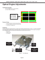
1
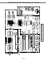
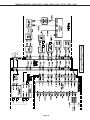
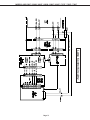
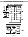
Ser vice
Manual
2005
MITSUBISHI ELECTRIC
DLP PROJECTION HDTV
V29 / V30 / V30+ / V31 CHASSIS
WD-52327
WD-52527
WD-62827
V29 Chassis
WD-52627
WD-62627
V30 Chassis
WD-52628
WD-62628
WD-73727
V30+ Chassis
WD-62827
WD-73827
V31 Chassis
WD-62927
WD-73927
Pb Solder
CAUTION:
Before servicing this chassis, it is important that the service person read the "SAFETY PRECAUTIONS" and
"PRODUCT SAFETY NOTICE" contained in this manual.
SPECIFICATIONS
•
•
•
•
Power Input
Power Usage
Light Engine
Light Source
• Channel Range
• Antenna Input
• Tuning (V29,V30)
:
:
:
:
:
:
AC 120V, 60Hz
See table on page 5
DLPTM (1920 x 1080 pixels)
120W [V29,V30(52"&62")]
150W [V30(73"),V30+,V31]
Air VHF - 2~13, UHF - 14~69
Analog Cable - 1~25
Digital Cable - 1~35
• Input Level
:
: VIDEO IN JACK (RCA Type)
1.0Vp-p 75Ω unbalanced
: AUDIO IN JACK (RCA Type)
-4.7dBm 43kΩ unbalanced
S-VIDEO IN JACK
(Y/C separate type)
Y:1.0 Vp-p C:0.286Vp-p(BURST)
75Ω unbalanced
: COMP / Y, Cr, Cb (RCA Type)
Y: 1.0 Vp-p Cr, Cb: 700mVp-p
: 2 RF 75Ω unbalanced
: 1 NTSC/ATSC/QAM
1 Out of Band for CableCARDTM
1 NTSC for PIP
: 2 NTSC/ATSC/QAM
1 Out of Band for CableCARDTM
2 NTSC for PIP
• Output Level
: VIDEO OUT JACK (RCA Type)
1.0Vp-p 75Ω unbalanced
: AUDIO OUT JACK (RCA Type)
-4.7dBm 4.7kΩ unbalanced
• Cabinet Dimensions
: See Table on page 5
• Digital
• Weight
: See table on page 5
: IEEE-1394 I/O Jacks
: Digital Audio Output
(RCA Type)
: HDMITM
:
MonitorLinkTM RS-232 Control
: Memory Card Reader
• Tuning (V30+, V31)
• Speakers (8 Ohms 10W)
: Two 1.5" Round
Two 5.5"x2.2" Oval
Pb Solder
: Lead-Free solder PWBs
• Design specifications are subject to change without notice.
MITSUBISHI DIGITAL ELECTRONICS AMERICA, INC.
9351 Jeronimo Road, Irvine, CA 92618-1904
Copyright © 2005 Mitsubishi Digital Electronics America, Inc.
All Rights Reserved
MODELS: WD-52627 / 52628 / 62627 / 62628 / 62827 / 62927 / 73727 / 73827 / 73927
CONTENTS
INTRODUCTION ................................................................................................................................ 5
Model Dimensions and Weight Specifiations ................................................................................... 5
PRODUCT SAFETY NOTICE ............................................................................................................. 5
SAFETY PRECAUTIONS ................................................................................................................. 6
DISASSEMBLY ................................................................................................................................. 7
Front Disassembly (WD-52627 / WD-52628 / WD-62627 / WD-62628............................................. 7
Front Disassembly (WD-62827) ...................................................................................................... 8
Front DisassembLY (WD-62927) ................................................................................................... 11
Front Disassembly (WD-73727 / WD-73827) ................................................................................. 15
Front Disassembly (WD-73927) .................................................................................................... 17
Rear Disassembly ........................................................................................................................ 19
Chassis Disassembly & Accessing PWBs ................................................................................... 20
Out of Cabinet Chassis Operation ................................................................................................. 26
Optical Engine Replacement ......................................................................................................... 29
DIAMOND SHIELDTM Removal ........................................................................................................ 34
SERVICING THE LENTICULAR LENS AND FRESNEL SCREEN ..................................................... 35
Removal of the Lenticular Screen and Fresnel Lens ...................................................................... 35
Installation of the Lenticular Screen and Fresnel Lens ................................................................... 36
ADJUSTMENTS ............................................................................................................................... 37
Option Menu & Defaults ................................................................................................................ 37
LED Indicator Diagnostics ............................................................................................................. 38
Error Codes Operational Check ..................................................................................................... 39
Remote Operational Mode ............................................................................................................ 40
Service Adjustment Mode ............................................................................................................. 40
Service Adjustment Mode Operation .................................................................................... 40
Resetting Data to factory values and Transferring data ......................................................... 41
Optical Engine Adjustment ............................................................................................................ 42
Test Signal activation ........................................................................................................... 42
Preliminary .......................................................................................................................... 42
Locking Screw ..................................................................................................................... 42
Trapezodial Distortion Adjustment ........................................................................................ 43
Rotation Adjustment............................................................................................................. 43
Hortizontal & Vertical Position.............................................................................................. 44
USING LEAD FREE SOLDER .......................................................................................................... 45
CHIP PARTS REPLACEMENT ......................................................................................................... 46
REPLACEMENT PARTS .................................................................................................................. 47
Parts Ordering .............................................................................................................................. 47
Critical and Warranty Parts Designation........................................................................................ 47
Parts Tolerance Codes .................................................................................................................. 47
Quick Reference List .................................................................................................................... 48
SERVICE PARTS LIST .................................................................................................................... 49
SCREEN ASSEMBLY PARTS LIST .................................................................................................. 60
WD-52627 / WD-52628 / WD-62627 / WD-62628 .......................................................................... 60
WD-62827 / WD-62927 ................................................................................................................. 71
WD-73727 / WD-73827 / WD-73927 ............................................................................................. 62
Page 3
MODELS: WD-52627 / 52628 / 62627 / 62628 / 62827 / 62927 / 73727 / 73827 / 73927
CIRCUITRY BLOCK DIAGRAMS ..................................................................................................... 63
Main Power Supply ....................................................................................................................... 63
Lamp Ballast DC Supply ............................................................................................................... 64
Fans Power Supply ....................................................................................................................... 64
Optical Engine Power Supply ........................................................................................................ 65
HDD Power Supply ((V30+ & V31 Only)........................................................................................ 65
Analog Video Signal Path ............................................................................................................. 66
Digital Video Signal Path .............................................................................................................. 67
HDD Record Signal Path ............................................................................................................... 68
Sound Signal Path ........................................................................................................................ 69
Command Input Circuitry ............................................................................................................... 70
Serial Data Control Lines .............................................................................................................. 70
Lamp Control Circuitry .................................................................................................................. 71
Lamp, Engine and Fan’s Protect circuitry ..................................................................................... 72
TV Guide On Screen® ................................................................................................................... 72
SCHEMATIC DIAGRAMS .....................................................................................................................
Page 4
MODELS: WD-52627 / 52628 / 62627 / 62628 / 62827 / 62927 / 73727 / 73827 / 73927
INTRODUCTION
This service manual provides service instructions for DLP Projection TV Models and Chassis:
Dimensions/Weight
MODEL
WD-52627
WD-52628
WD-62627
WD-62628
WD-62827
WD-62927
WD-73727
WD-73827
WD-73927
CHASSIS HEIGHT
V29
V30
V29
V30
V30+
V31
V30
V30+
V31
34 in.
"
40.5 in.
"
"
"
44.8 in.
"
"
WIDTH
DEPTH
WEIGHT
49.6 in.
"
58.3 in.
"
60.3 in.
"
69.9 in.
"
69.8 in.
18.6 in.
"
20.3 in
"
"
"
21.5 in.
"
"
121 lbs.
"
133 lbs.
"
"
"
165 lbs.
"
"
POWER
USAGE
295W
"
"
"
310W
330W
335W
350W
"
This service manual includes:
1. Assembly and disassembly instructions for the front and rear cabinet components.
2. Servicing of the Lenticular Screen and Fresnel Lens.
3. Servicing down to major components, chassis, PWBs, Light Engine, Lamp Ballast, etc..
4. Electrical adjustments.
5. Optical Adjustments.
6. Lead Free Soldering.
7. Chip parts replacement procedures.
8. Simplified circuit path diagrams.
The parts list section of this service manual includes:
1. Cabinet and screen parts.
2. Electrical parts.
Block diagrams of the above listed models are included in this service manual for better understanding of the circuitry.
PRODUCT SAFETY NOTICE
Many electrical and mechanical parts in television receivers have special safety related characteristics. These characteristics are often not evident from visual inspection nor can the protection afforded by them necessarily be obtained by
using replacement components rated for higher voltage, wattage, etc.
Replacement parts which have special safety characteristics are identified in this service manual.
Electrical components having such features are identified by shading on the schematic diagram and by bold type in
the parts list of this service manual. Therefore, the replacement for any safety part should be identical in value
and characteristics.
Pb Solder
The PWBs used in the V29, V30, V30+ and V31 chassis are constructed using Lead-Free solder.
When servicing use only recommended Lead-Free solder (refer to page 45).
CableCARD is a trademark of Cable Television Laboratories, Inc.
TV Guide On Screen is a registered trademark of Gemstar Development Corp.
HDMI is a trademark of HDMI Licensing, LLC.
Digital Light Processing, Digital Micromirror Device and DLP are trademarks of Texas Instruments.
Page 5
MODELS: WD-52627 / 52628 / 62627 / 62628 / 62827 / 62927 / 73727 / 73827 / 73927
SAFETY PRECAUTIONS
NOTICE:
WARNING:
1.
2.
Observe all cautions and safety related notes located inside the receiver cabinet and on the
receiver chassis.
Operation of this receiver outside the cabinet or with the cover removed presents a shock hazard
from the receiver's power supplies. Work on the receiver should not be attempted by anyone who is
not thoroughly familiar with the precautions necessary when working on high voltage equipment.
When service is required, observe the original lead dress. Extra precaution should be taken to
assure correct lead dress in the high voltage area. Where a short-circuit has occurred, replace those
components that indicate evidence of overheating.
WARNING ... RISK OF EYE INJURY
Do not look into the light source, lens or mirror when operating the TV
Leakage current check
Before returning the receiver to the customer, it is recommended that leakage current be measured according to the
following methods.
1. Cold Check
With the alternating current (AC) plug removed from the AC source, place a jumper across the two AC plug
prongs. Connect one lead of an ohm meter to the AC plug and touch the other lead to each exposed metal part
(i.e. antennas, handle bracket, metal cabinet, screw heads, metal overlay, control shafts, etc.), particularly any
exposed metal part that has a return path to the chassis. The resistance of the exposed metal parts having a
return path to the chassis should be a minimum of 1Meg Ohm. Any resistance below this value indicates an
abnormal condition and requires corrective action.
2. Hot Check ...Use the circuit shown below to perform the hot check test.
1. Keep switch S1 open and connect the receiver to the measuring circuit. Immediately after
connection, and with the switching devices of the receiver in their operating positions, measure the
leakage current for both positions of switch S2.
2. Close switch S1, energizing the receiver. Immediately after closing switch S1, and with the
switching devices of the receiver in their operating positions, measure the leakage current for both
positions of switch S2. Repeat the current measurements of items 1 and 2 after the receiver has
reached thermal stabilization. The leakage current must not exceed 0.5 milliampere (mA).
Page 6
MODELS: WD-52627 / 52628 / 62627 / 62628 / 62827 / 62927 / 73727 / 73827 / 73927
CABINET FRONT DISASSEMBLY
(WD-52627 / WD-52628 / WD-62627 / WD-62628)
SPEAKER GRILLE & BEZEL Removal
1) Pull the SPEAKER-GRILLE away from the cabinet to remove.
2) Pull the BEZEL from the cabinet.
SCREEN-ASSY Removal
1) Remove 10 screws (a) from the upper cabinet rear cover (3 screws on each side and 4 screws across the
top).
2) Remove screws (b) along the bottom of the SCREEN-ASSY (8 screws on 52 inch models, and 10 screws
on 62 inch models),
3) Unplug the LL connector to the front CONTROL-PANEL.
4) Lift the SCREEN-ASSY up slightly and then pull away from the cabinet.
CARD READER Removal
1) Remove two screws (c) securing the Card
Reader.
2) Pull the Card Reader from the cabinet.
3) Disconnect the ground lead, USB and 1394
connectors to the Card Reader.
Page 7
MODELS: WD-52627 / 52628 / 62627 / 62628 / 62827 / 62927 / 73727 / 73827 / 73927
WD-62827 Front Disassembly
FRONT PANEL CAPS Removal
Pull the FRONT PANEL CAPS from the unit.
TOP TRIM and FRONT ESCUTCHEON Removal
1) Remove screw (a) to remove the TOP
TRIM.
2) Pull off the FRONT-ESCUTCHEONS.
Page 8
MODELS: WD-52627 / 52628 / 62627 / 62628 / 62827 / 62927 / 73727 / 73827 / 73927
WD-62827 Front Disassembly (continued)
SIDE-TRIM Removal
1)
Remove screws (a) and (b) on each
side of the unit.
2)
Pull off the SIDE-TRIM on each side.
BEZEL and Card Reader/Contol Assy. Removal
1) Remove screws (c) to remove the BEZEL.
2) Remove screws (d), pull the Card Reader/
Control Assy. out the front of the unit.
3) Unplug the LL, CE1, J8202 and 1394
connectors to remove the Assembly completely.
Page 9
MODELS: WD-52627 / 52628 / 62627 / 62628 / 62827 / 62927 / 73727 / 73827 / 73927
WD-62827 Front Disassembly (continued)
SCREEN ASSY Removal
1) Remove screws (e) from the top and sides of the upper rear cover.
2) Remove screws (d) from the bottom of the SCREEN ASSY.
3) Lift the SCREEN ASSY up slightly and pull away from the cabinet.
Page 10
MODELS: WD-52627 / 52628 / 62627 / 62628 / 62827 / 62927 / 73727 / 73827 / 73927
WD-62927 Front Disassembly
FRONT ESCUTCHEONS, CARD READER/CONTROL Assy and PEDESTAL COVER Removal
1) Pull the Right and Left Front Escutcheons from the cabinet.
2) Pull the Pedestal Cover forward to remove.
3) Remove screw (a) to remove the Card Reader/Control Assembly from the front.
(To remove the assembly completely unplug the LL, CE1 J8202 and 1394 connectors.)
Page 11
MODELS: WD-52627 / 52628 / 62627 / 62628 / 62827 / 62927 / 73727 / 73827 / 73927
WD-62927 Front Disassembly (continued)
TOP, BOTTOM and SIDES TRIM Removal
1) Remove screws (b) to remove the Top Trim.
2) Remove screws (c) to remove the Bottom Trim.
3) Remove screws (d) on both sides to remove the Side Trim
Page 12
MODELS: WD-52627 / 52628 / 62627 / 62628 / 62827 / 62927 / 73727 / 73827 / 73927
WD-62927 Front Disassembly (continued)
FRONT BEZEL Removal
1) Remove screws (e) from the FRONT-BEZEL.
2) Pull the FRONT-BEZEL from the cabinet.
Page 13
MODELS: WD-52627 / 52628 / 62627 / 62628 / 62827 / 62927 / 73727 / 73827 / 73927
WD-62927 Front Disassembly (continued)
SCREEN ASSEMBLY Removal
1) Remove screws (f) from the upper rear cover (3 at each side and 4 acrross the ).
2) Remove screws (g) at the bottom of the screen.
3) Lift the Screen Assembly slighly and pull away from the unit.
Page 14
MODELS: WD-52627 / 52628 / 62627 / 62628 / 62827 / 62927 / 73727 / 73827 / 73927
WD-73727 / WD-73827 Front Disassembly
CARD READER REMOVAL
1) Pull the two PANEL-FRONTs from the cabinet.
2) Remove screws ((a) from the Card Reader.
3) Slide the Card Reader and Control Assembly out the front of the TV.
(To remove the Card Reader completely unplut the connectore LL, CE1, J8202 and 1394.)
Page 15
MODELS: WD-52627 / 52628 / 62627 / 62628 / 62827 / 62927 / 73727 / 73827 / 73927
WD-73727 / WD-73827 Front Disassembly (continued)
GRILLE-SIDE REMOVAL
1) Remove screw (b) in the GRILLE-SIDE
LEFT and GRILL-SIDE RIGHT
2) Pull the two GRILLE-SIDEs from the unit.
SCREEN-ASSY REMOVAL
1) Remove screw (c) along the top and sides
of the upper rear cover. (4 across the top
and 3 on each side).
2) Remove two screw (d) on the bottom on the
SCREEN-ASSY.
3) Lift the SCREEN-ASY slightly and pull it
away from the TV.
Page 16
MODELS: WD-52627 / 52628 / 62627 / 62628 / 62827 / 62927 / 73727 / 73827 / 73927
WD-73927 Front Disassembly
CARD READER REMOVAL
1) Pull of the right and left GRILLE-SIDEs.
2) Remove screws (a) to remove the FRONT-BOARDS.
3) Remove screws (b) and pull the Card Reader and Control Assembly out the front of the TV.
Page 17
MODELS: WD-52627 / 52628 / 62627 / 62628 / 62827 / 62927 / 73727 / 73827 / 73927
WD-73927 Front Disassembly (continued)
SCREEN-ASSY Removal
1) Remove screws (f) along the top and sides of the upper rear cover. (4 across the top and 3 on each side).
2) Remove two screw (g) on the bottom on the SCREEN-ASSY.
3) Lift the SCREEN-ASY slightly and pull it away from the TV.
Page 18
MODELS: WD-52627 / 52628 / 62627 / 62628 / 62827 / 62927 / 73727 / 73827 / 73927
Cabinet Rear Disassembly
BACK-COVER Removal
1) Remove screws (a) and (b) from the the BACK-COVER.
2) Pull the BACK-COVER from the set.
Accessing the MIRROR from the rear (52 and 62 inch models ONLY)
1) Remove screws (c).
2) Pull the Rear Mirror Access panel from the unit.
Page 19
MODELS: WD-52627 / 52628 / 62627 / 62628 / 62827 / 62927 / 73727 / 73827 / 73927
Chassis Disassembly / Accessing PWBs
Note: Although not individually indicated, unplug the required connectors in each
disassembly step.
Chassis Sequence of Disassembly
REMOVE
Chassis Top Cover
(Fig. 1)
REMOVE
PWB-POWER
(Fig. 3)
REMOVE
Assy PWB-TERMINAL
(Fig. 2)
REMOVE
Chassis Top Shield
(Fig. 3)
REMOVE
PWBs MICRO / FMT/ RISER
(Figs. 4 & 5)
REMOVE
Chassis Rear Shield
(Fig. 6)
REMOVE
PWB-DM
(Fig. 7)
Page 20
MODELS: WD-52627 / 52628 / 62627 / 62628 / 62827 / 62927 / 73727 / 73827 / 73927
Chassis Removal from the cabinet
After removing the Rear Cover:
1) Remove screw (a), (b) and (c) to remove the
back terminal board cover. (Figure A)
2) Remove screw (d) to remove the support bracket
on each side of the chassis. (Figure B)
3) Remove the chassis mounting screws (e) on
each side of the chassis. (Figure (C)
4) Unplug all connectors to the chassis and
carefully slide the chassis from the cabinet.
Figure A
Figure B
Figure C
Page 21
MODELS: WD-52627 / 52628 / 62627 / 62628 / 62827 / 62927 / 73727 / 73827 / 73927
Chassis Cover Removal (Figure 1)
1) Remove the 3 screws (a).
2) Lift the Cover from the chassis.
Figure 1: Chassis Cover Removal
Assy PWB- TERMINAL Removal (Figure 2)
1) Remove 7 screws (b) to remove
the TERMINAL-INLAY.
2) Remove 3 screws (c) to remove
the Assy PWB-TERMINAL.
Figure 2: ASSY PWB-TERMINAL Removal
Page 22
MODELS: WD-52627 / 52628 / 62627 / 62628 / 62827 / 62927 / 73727 / 73827 / 73927
PWB-POWER Removal (Figure 3)
1) Remove four screws (d).
2) Disconnect all connectors to PWB-POWER.
3) Lift PWB-POWER from the chassis.
Chassis Upper Shield Removal (Figure 3)
1) Remove seven screws (e).
2) Lift the Shield from the chassis.
Figure 3: PWB-POWER and Chassis Upper Shield
Page 23
MODELS: WD-52627 / 52628 / 62627 / 62628 / 62827 / 62927 / 73727 / 73827 / 73927
PWB-MICRO Removal
Referring to Figures 4 & 5 .
1) Remove the 2 HDMI socket screws (f).
2) Remove 3 mounting screws (g) from PWB-MICRO.
2) Unplug PWB-MICRO from PWB-RISER
and remove it from the chassis.
Figure 5: PWB-MICRO Mounting Screws
Figure 4: HDMI Socket Screws
PWB-FORMAT & PWB=RISER Removal
Referring to Figures 6
After removing PWB-MICRO:
1) Remove screw (h).
2) Unplug the PWB-FORMAT and
PWB-RISER from PWB-DM.
Figure 6: PWB-FORMAT & RISER Removal
Page 24
MODELS: WD-52627 / 52628 / 62627 / 62628 / 62827 / 62927 / 73727 / 73827 / 73927
PWB-DM Removal
Chassis Rear Shield Removal (Figure 7)
1) Remove 7 screw ( j )
2) Remove 2 nuts ( j1 )
3) Pull off Chassis Rear Shield.
Figure 7: Chassis Rear Shield
PWB-DM Removal (Figures 8)
1) Remove 3 screws (k) holding the PWB-MICRO
Support Bracket.
2) Remove the Support Bracket.
3) Remove the five screws (m).
4) Remove the PWB-DM from the chassis.
Figure 8: PWB-DM Removal
Page 25
MODELS: WD-52627 / 52628 / 62627 / 62628 / 62827 / 62927 / 73727 / 73827 / 73927
OPERATING CHASSIS OUTSIDE OF CABINET
1) Remove screws from back terminal board.
Screws A = (7), B = (2), C = (2)
2) Remove support bracket screws D = (4), and
mounting screw E = (1)
A
D
B
C
E
3) Support bracket has latch that must be opened
before removing from unit
4) Remove mounting screw F = (1) on right side
of chassis behind bracket
latch
support bracket
F
5) Disconnect AC cord from connector PS and
disconnect connector CE1
6) Pull chassis from cabinet. Rotate to side as
pictured below and remove screws G = (2)
CE1
PS
G
Page 26
MODELS: WD-52627 / 52628 / 62627 / 62628 / 62827 / 62927 / 73727 / 73827 / 73927
7) Pictured below is proper wire routing, please
verify during re-assembly
8) Disconnect connector PL and remove screw
H = (1)
H
PL
PL
9) Remove connectors PC, PA1, PB, PD and
DVI cable
PC
PA1
10) Remove cover shield for Power PWB. Disconnect connectors FB, ES, KA, PD, PC, J7T01
J7T01
PB
DVI
PC
PD KA
PD
11) Remove screws from side and front of
chassis I =(4)
ES
FB
12) Remove screws from side of chassis J = (3)
and from terminal K = (3)
ck
Ba
t
Fron
J
I
Page 27
K
MODELS: WD-52627 / 52628 / 62627 / 62628 / 62827 / 62927 / 73727 / 73827 / 73927
13) Pull Terminal PWB from chassis assembly
and remove fan connector JD from Micro PWB
14) Setup power section next to remaining
chassis section as pictured below.
JD
NOTE: Unit can be operated without Terminal
PWB or Chassis Fan installed. Without Fan
connected, TV will shutdown if Micro PWB
(Bottom side) temperature becomes too hot.
NOTE: It is recommened to use a separate AC
cord. You can purchase one from the parts
department: P/N 246C351070
AC Cord
Bolt Table:
3
3
4
Screw Size: 3x12
12 Used @: A / C
Screw Size: 3x8
8 Used @: B / G / H / I / J / K
Screw Size: 4x16
16 Used @: D / E / F
Page 28
MODELS: WD-52627 / 52628 / 62627 / 62628 / 62827 / 62927 / 73727 / 73827 / 73927
OPTICAL ENGINE REPLACEMENT
Pull engine from base and remove all the listed parts on this page and transfer them to new
engine. Then transfer EEPROM data and realign mechanical.
(See following pages for details)
LAMP DUCT
ENGINE-PWR-PWB
LENS CUSHION
BALLAST PLATE
ENGINE PLATE
INTERFACE PWB
BOTTOM PLATE
LAMP CARTRIDGE
LAMP FAN
(View from front)
Lamp Duct
Lens Cushion
Bottom Plate
Engine Plate
Lamp Fan
(120W Version)
(note on 150W version
Lamp Fan is in front)
(View from back)
Ballast Plate
Ballast Fan
Engine PWR PWB
Ballast Cover
Lamp Cartridge
Interface PWB
Page 29
MODELS: WD-52627 / 52628 / 62627 / 62628 / 62827 / 62927 / 73727 / 73827 / 73927
OPTICAL ENGINE REPLACEMENT (Details)
1) Remove screws (3)
2) Remove mounting screw
3) Disconnect JA, JF, LT connectors
4) Disconnect JC and CD connectors
LT
JC
JA
CD
JF
5) Remove DVI cable and disconnect
JE and DT connectors
JE
6) Remove wire tie near support post
DVI
DT
Page 30
MODELS: WD-52627 / 52628 / 62627 / 62628 / 62827 / 62927 / 73727 / 73827 / 73927
OPTICAL ENGINE REPLACEMENT (Details)
7) Remove (3) screws from Interface PWB
8) Remove CJ3 connector from Interface PWB
CJ3
9) Remove (2) screws from Side Lock
10) Route wiring so that it does not snag
on support post.
11) Disconnect PA1 and J3 connectors
and remove Engine-PWR-PWB
12) Pull Optical Engine from cabinet. (Note:
Slight twisting motion may be required)
J3
PA1
Page 31
MODELS: WD-52627 / 52628 / 62627 / 62628 / 62827 / 62927 / 73727 / 73827 / 73927
OPTICAL ENGINE REPLACEMENT (Details)
13) Remove (3) screws from Lamp Duct
14) Remove (2) screws from Lamp
Cartridge - and remove Lamp Cartridge
15) Remove (4) screws from Ballast Plate
16) Remove Bottom Plate from Engine Plate.
Remove (5) screws A - B - C
A
B
C
Page 32
MODELS: WD-52627 / 52628 / 62627 / 62628 / 62827 / 62927 / 73727 / 73827 / 73927
OPTICAL ENGINE REPLACEMENT (Details)
17) Be sure not to misplace spring
18) Remove (1) screw from plate
(A), (4) screws from fan (B), (2)
screws from side lock (C) and (2)
grounding strap screws (D)
C
D
Spring
A
B
19) Transfer LENS COVER from
service part to defective part
Reassembly:
1) Attach LENS CUSHION BASE to Engine
Lens Cushion Base
Follow above steps in reverse order
TIP: Lift and group wiring on left
side of engine when installing
Mechanical Alignment: Adjustment is required after engine has been removed. Please follow steps
in the adjustment section of this manual.
Data: Index Delay Data needs to be transfered from Engine to E2P PWB:
< MENU + 2457 + 0 >
Select -> COPY LIGHT ENGINE EEPROM TO DM
PRESS ENTER
Page 33
MODEL: WD-52627
WD-52525 // WD-52725
/ WD-52825
/ WD-62525
/ WD-62725
/ WD-62825
MODELS:
52628 / 62627
/ 62628 /62827
/ 62927
/ 73727 / 73727
/ 73927
DIAMOND SHIELD REPLACEMENT
(WD-62927 / WD-73927 Only)
2
To Remove the Diamond Shield:
1. While wearing soft cotton gloves, loosen the
sides of the Diamond Shield by pressing a small
plastic card (the size of a standard credit card or a
clean, plastic, putty knife) into the middle of the
side slot. The Diamond Shield side will snap out
of the top middle and bottom clips. Loosen both
sides before proceeding to step 2.
1
1
1
1
1
1
2. After the sides are free, gently push down on the
top of the Diamond Shield. It will slide out of the
top channel.
3
3 Carefully pull the screen up to remove it from the
bottom channel. Store the Diamond Shield in a clean,
dust free area, where it will not be scratched.
To Install the Diamond Shield:
5
4. Slide the Diamond Shield into the bottom channel,
making sure it fits securely.
6
5. Press gently on the top of the Diamond Shield to
slightly bow the screen towards you. Insert the
top of the Diamond Shield into the top channel. It
should fit securely.
6
6
6
6
6
6. At each side, gently press the top, middle and
bottom of the Diamond Shield to snap it back into
place.
4
WARNING
Sharp edges! Always wear gloves to
handle, lift, install and remove the
Diamond Shield.
Page
Page17
34
MODELS: WD-52627 / 52628 / 62627 / 62628 / 62827 / 62927 / 73727 / 73827 / 73927
SERVICING THE LENTICULAR SCREEN AND FRESNEL LENS
CAUTION:
Wear gloves when handling the Lenticular Screen and Fresnel Lens.
This prevents cuts and finger prints. Do not place Fresnel Lens in the sun.
This may cause fire and heat related injuries.
Lenticular Screen and Fresnel Lens Removal
1. Remove the screen assembly as shown in the Cabinet Disassembly procedure.
2. Remove the four screws (a) to remove the bottom of the SCREEN-FRAME-BOTTOM . (Figure 1)
3. From the rear of the screen assembly, carefully slide the Lenticular Screen and Fresnel Lens combination
from the Screen Frame. (Figure 2)
Note: When separating the Lenticular Screen from the Fresnel Lens, use caution
while prying the Screen and Lens apart. Use a slot type screw driver, and
remove the pressure sensitive double sided tape.
Figure 1
Page 35
MODELS: WD-52627 / 52628 / 62627 / 62628 / 62827 / 62927 / 73727 / 73827 / 73927
SERVICING THE LENTICULAR SCREEN AND FRESNEL LENS
Lenticular Screen and Fresnel Lens Installation
Note: Store the Lenticular Screen and Fresnel Lens in a cool dry place. High humidity may
deform the Lenticular Screen and Fresnel Lens.
1. Apply double coated tape (Part #LENS-TAPE) along the top rear edge of the Lenticular Screen, as shown
below. Refer to the table below for the tape length.
2. Sandwich the Fresnal Lens and Lenticular Screen together. The Lenticular Screen label must be towards
the front and the Fresnel Lens label towards the rear. (Figure 2)
3. Apply pressure at the top edge to bond the screens together.
4. Reverse the Screen Removal procedure and insert the screens in the Screen Fame Assembly.
Figure 1
Page 36
MODELS: WD-52627 / 52628 / 62627 / 62628 / 62827 / 62927 / 73727 / 73827 / 73927
OPTION MENU
1. Press the “MENU” button on the remote hand unit.
2. Press the buttons “2”, “4”, “7” and “0” in order.
(The screen will change to the option menu.)
Initial Main Menu Defaults
Setup Menu
Language
Combine Channel View
Clock
Clock Setting
Time
Date
Time Zone
Daylight Savings Time
Timer
Lamp Reminder
Software Version
NetCommand Menu
Edit
Icon Order
Transport Menu
Fixed Channel for Cable Box
Record
Record
Channel
Record to
Duration
Start Time
Day
Record List
Default Record Device
Analog Recordings
Channel
Antenna
Prefer Digital
Channel
Memory
Name
SQV
Signal Strength
Captions Menu
Analog Captions
Background
Digital Caption
Appearance
DigitalSettings
Font
Size
Color
Background
Opacity
Background Opacity
V-Chip Lock Menu
V-Chip
TV Rating
FV-Fantasy Violence
D-Sexual Dialog
English
-Manual
12:00pm
-----
--On
3 (gray out)
2
-1 hr
---Gray out
Anamorphic
1
-2
Added
---On if Mute
Gray
On if Mute
Default
Font 3
Large
White
Black
Translucent
Translucent
Off
TV-PG
Enable
Enable
L-Adult Language
S-Sexual Situationss
V-Violence
Programs Not Rated
Movie Rating
V-Chip Time
Start
Stop
Lock by Time
Lock by Time
Lock Time
Unlock Time
Front Button Lock
Audio/Video
A/V Memory Reset
Settings
Audio
Bass
Treble
Balance
Surround
Listen to (Analog Only)
Level Sount (Analog Only)
Language (Digital Only)
Video
Contrast
Brightnes
Sharpness
Color
Tint
Color Temp
Video Noise
Film Mode (Auto)
Define Edge
Color Balane
Video Mute
black Enhancement
TV Speakers
TV Volune
PIP Source
PIP Position
POP Position
PIP/POP Format
Format
Ant-1,2 (480i/480p)
Ant -1,2 (HD Digital)
Input 1,2,3
Comp-1,2,3
HDMI-1,2 (Video)
HDMI-2(PC)
Card Reader Video
Analog PC (v31 ONLY)
Page 37
Enable
Enable
Enable
Enable
PG
12:00pm
12:00pm
On
12:00pm
12:00pm
Off
An