1
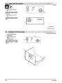
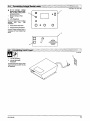
OM-180 800
Eff.
Miller
w/Style
April 1997
Number KH17
Processes
Automatic
Welding
The Power fBlue.
Description
Automatic
Welding System
Tooth ~
wI~~~t~r
OWNERS
MANUAL
From Miller to You
congratulations on choosing Miller. Now
get the job done and get it done right. We know
Thank you and
you
can
have time to do it any other way.
you dont
Thats
when Niels Miller first started
building arc
welders in 1929, he made sure his products offered
long-lasting value and superior quality. Like you, his
customers couldnt afford anything less. Miller products
had to be more than the best they could be. They had to
be the best you could buy.
why
people that build and sell Miller products continue the
Theyre just as committed to providing equipment and service
meets the high standards of quality and value established in 1929.
Today,
the
tradition.
that
This Owners
Miller
help
designed to help you get the most out of your
Please take time to read the Safety precautions. They will
Manual is
products.
you protect
yourself against potential
hazards
made installation and
_____________
ISO 0001
With Miller you
the worksite. Weve
operation quick
can count on
and easy.
years of reliable
service with proper maintenance. And if for
some reason the unit needs repair, theres a
____________
IQUALITY
on
SYSTEM
_____________
Troubleshooting section that will help you
figure out what the problem is. The parts list
will then help you to decide which exact part
you may need to fix the problem. Warranty and
service information for your particular model
are also provided.
Miller Is the tbst
welding
equipment manufacturer IN
the U.S.A. to be registered
to the ISO 9001 QualIty
System Standard.
T~1~ffl~ r~imnr~
L~5
Working as hard as you do
every power source from
Miller Is backed by the most
hassle-free warranty In the
business.
Miller Electric manufactures
of welders and
welding
For information
products,
to
on
a
full line
related
other
equipment.
quality Miller
contact your local Miller distributor
receive the latest full line
individual
catalog
catalog
or
sheets. To locate your nearest
distributor call 1-800-4-A-Miller.
TI/A Miller
The Power fBlue.
To~th S~c~
Features
Descrintlon
designed to provide touch
sensing capability using the welding wire and
voltage sense leads. The robot controller sends a
signal to the Touch Sensor to begin touch sensing
operation. A signal is sent from the Touch Sensor
to the robot controller when the welding wire
The Touch Sensor is
115
VAC, 2 A, 60 Hz Input Power
170
VDC, 5 mA Touch Sense Output
Touch Sensor And
Input
Power Pilot
Lights
External Connections For Cords And Cables
Product features and specifications
to change without notice
are
subject
touches the weldment.
The contactor in the Touch Sensor prevents any
low impedance path through the welding power
source during touch sensing operation. It also
operates during the weld cycle by closing before
welding
welding
no
Processes
Automatic
Welding
begins and remains closed during the
operation by sensing weld current. When
weld current is detected, the contactor
deenergizes.
Call
1 -800-4-A-MILLER
for your local
Miller distributor.
Your distributor
gives
Table of Contents
you
Page
Section
Service
You
always get the fast,
reliable response you
need. Most replacement
parts can be in your
hands in 24 hours.
Support
Need fast
answers
to the
1.
Safety Precautions
1.
Consignes
de sØcuritØ
1
5
2. Introduction
9
3. Installation
9
tough welding questions?
Contact your distributor.
The expertise of the
distributor and Miller is
there to help you, every
step of the way.
4.
12
Operation
5. Maintenance and
Troubleshooting
12
Miller offers a Technical Manual
which provides more detailed
service and parts information for
your unit. To obtain a Technical
Manual, contact your local
distdbuto, Your distributor can also
supply you with Welding Process
Manuals such as SMAW, GTAW,
GMAVvandGMAW-P
For practical in formation
6. Electrical
7. Parts List
Warranty
Diagram
on
welding,
14
process applications, and Miller
products, visit our website at
16
www.mlllerwelds.com
1.
Safety PrecautioNs
Read Before Using
.~.
~1 1
Symbol Usage
,...,...
.~.
~
..
OM-186 360- 4/97,
Marks
a
1 2
The
This group of symbols means Warning! Watch Out! possible
ELECTRIC SHOCK, MOVING PARTS, and HOT PARTS hazards.
Consult symbols and related instructions below for necessary
actions to avoid the hazards.
special safety message.
f~ Means Note;
A
Arc
not
safety related.
Welding
symbols
Hazards
are used throughout this manual
identify possible hazards. When you
shown below
to call attention to and
symbol, watch out, and follow the related instructions
safety information given below is
only a summary of the more complete safety information
found in the Safety Standards listed in Section 1.4. Read and
follow all Safety Standards.
see
4/97
Means Warning! Watch Out! There are possible
hazards with this procedure! The possible hazards are
shown in the adjoining symbols.
a
A
safety_som
the
Do not
with
a
to avoid the hazard. The
A
Only qualified persons should Install, operate, maintain,
repair this unit.
A
During operation, keep everybody, especially children, away.
~ can.kIiL.
and
over your body.
grounding of the workpiece is required, ground it directly
separate cable do not use work clamp or work cable.
Do not touch electrode if you are in contact with the
or another electrode from a different machine.
work, ground,
only well-maintained equipment. Repairor replace damaged
parts at once. Maintain unit according to manual.
Use
Wear
~
drape cables
If earth
a
safety harness
Keep all panels and
if
working
covers
above floor level.
securely
in
place.
Clamp work cable with good metal-to-metal
or worktable as near the weld as practical.
contact to
workpiece
Insulate work
workpiece
to
clamp when not connected
object.
to
prevent
contact with any metal
live electrical parts can cause fatal
shocks or severe burns. The electrode and work
circuit is electrically live whenever the output is on.
The input power circuit and machine internal
circuits are also live when power is on. In semiautomatic or
automatic wire welding, the wire, wire reel, drive roll housing, and all
metal parts touching the welding wire are electrically live. Incorrectly
installed or improperly grounded equipment is a hazard.
Touching
SIGNIFICANT DC VOLTAGE exists after removal of
input power on inverters.
Turn Off
inverter, disconnect input power, and discharge input
capacitors according
before
touching
to instructions in Maintenance Section
any parts.
Do not touch live electrical
parts.
dry, hole-free insulating gloves and body protection.
Wear
Insulate
a
yourself from work and ground using dry insulating mats
big enough to prevent any physical contact with the
ground.
fumes and gases. Breathing
these fumes and gases can be hazardous to your
health.
Welding produces
or covers
work
or
Do not use AC
there is
a
Use AC
If AC
output in damp areas,
danger of falling.
ONLY if
output
output
is
required,
required
use
if movement is confined,
if
Keep your head
for the
remote
or
welding process.
output
control if
present
on
out of the fumes. Do not breathe the fumes.
If inside, ventilate the area and/or
remove welding fumes and gases.
unit.
If ventilation is poor,
input power or stop engine before installing or
servicing this equipment. Lockout/tagout input power according
to OSHA 29 CFR 191 0.147 (see Safety Standards).
Read the
Disconnect
Properly install
Owners
and
ground
this
equipment according
to its
Manual and national, state, and local codes.
the supply ground
check and be sure that input
power cord ground wire is properly connected to ground terminal
in disconnect box or that cord plug is connected to a properly
grounded receptacle outlet.
Always verify
When
making input connections, attach proper grounding
conductor first
double-check connections.
Frequently inspect input power cord for damage or bare wiring
replace cord immediately if damaged bare wiring can kill.
Turn off all
Do not
equipment
use worn,
OM-186 360
when not in
use.
damaged, undersized,
or
poorly spliced cables.
Material
manufacturers
use an
Safety
use
exhaust at the
arc
to
approved air-supplied respirator.
Data
Sheets
(MSDSs)
instructions for metals, consumables,
and
the
coatings,
cleaners, and degreasers.
a confined space only if it is well ventilated, or while
wearing an air-supplied respirator. Always have a trained watchperson nearby. Welding fumes and gases can displace air and
lower the oxygen level causing injury or death. Be sure the
breathing air is safe.
Work in
Do not weld in locations near degreasing, cleaning, or spraying
The heat and rays of the arc can react with vapors to
operations.
form highly
toxic and
Do not weld
irritating gases.
coated metals, such as galvanized, lead, or
cadmium plated steel, unless the coating is removed from the
weld area, the area is well ventilated, and if necessary, while
on
wearing an air-supplied respirator. The coatings and any metals
containing these elements can give off toxic fumes if welded.
1
eyes and skin
~m
Arc rays from the welding process produce intense
visible and invisible (ultraviolet and infrared) rays
that can burn eyes and skin. Sparks fly off from the
weld.
I
Shut oft
shielding gas supply when
not in use.
Always ventilate confined spaces
approved air-supplied respirator.
Ci
or
use
Weara welding helmet fitted with a proper shade of filterto protect
your face and eyes when welding or watching (see ANSI Z49.i
and Z87.1 listed in
Wear
Safety Standards).
approved safety glasses
.~caflcat
with side shields under your
Use
parts bare handed.
cooling period before working on gun
Do not touch hot
helmet.
Allow
protective screens or barriers to protect others from flash and
others not to watch the
or
torch.
glare;
warn
Wear
protective clothing made from durable, flame-resistant
(leather and wool) and foot protection.
arc.
material
MAGNETIC FIELDS can affect pacemakers
InÆse
fir
expISion~.
Pacemaker
keep away.
wearers
Wearers should consult their doctor before
closed containers, such as tanks,
pipes, can cause them to blow up. Sparks
fly oft from the welding arc. The flying sparks,
Welding
drums,
can
on
going near arc welding, gouging,
welding operations.
or
or
spot
hot workpiece, and hot equipment can cause fires
and burns. Accidental contact of electrode to metal objects can
cause sparks, explosion, overheating, or fire. Check and be sure the
area is safe before doing any welding.
Protect
yourself
and others from
and hot metal.
flying sparks
Noise from
Do not weld where
flying sparks
can
strike flammable material.
Remove all flammables within 35 ft (10.7 m) of the welding arc. If
possible, tightly cover them with approved covers.
Wear
this is not
fire,
and
Be
that
welding
aware
can cause
fire
on
keep
a
fire
on a
as
Connect work cable to the work
approved
ear
protection
if noise level is
as
to
close to the
Shielding gas cylinders contain gas under high
pressure. If damaged, a cylinder can explode.
Since gas cylinders are normally part of the welding
process, be sure to treat them carefully.
pipes,
AWS F4.1 (see
or
welding
area as
to
welder to thaw frozen
mechanical shocks,
Install
pipes.
Remove stick electrode from holder
tip when not in use.
or
cut off
welding
compressed gas cylinders from excessive heat,
slag, open flames, sparks, and arcs.
Protect
prevent welding current from traveling long, possibly
unknown paths and causing electric shock and fire hazards.
cylinders in an upright position by securing to a stationary
or cylinder rack to prevent falling or tipping.
support
wire at
contact
Keep cylinders away from any welding
Wear oil-free
Never
protective garments such
as
shirt, cuffless trousers, high shoes, and
a
leather
FLYING METAL
can
gloves, heavy
cap.
Remove any combustibles, such as a butane
from your person before doing any welding.
drape
Never allow
lighter or matches,
Never weld
a
a
welding
welding
on a
torch
over a
or
gas
approved safety glasses with side
shields even under your welding helmet.
cylinder.
electrode to touch any
pressurized cylinder
cylinder.
explosion
will result.
only correct shielding gas cylinders, regulators, hoses, and
fittings designed for the specific application; maintain them and
associated parts in good condition.
Turn face away from valve outlet when
Wear
other electrical circuits.
Use
Injure eyes
Welding, chipping, wire brushing, and grinding
cause sparks and flying metal. As welds cool,
they can throw off slag.
2
can
partition
or
tanks, drums,
they are properly prepared according
Safety Standards).
use
equipment
the hidden side.
unless
Do not
or
extinguisher nearby.
ceiling, floor, bulkhead,
Do not weld enclosed containers such
practical
processes
high.
Be alert that welding sparks and hot materials from welding can
easily go through small cracks and openings to adjacent areas.
Watch for
some
damage hearing.
.
opening cylinder
valve.
Keep protective cap in place over valve except when cylinder is in
use or
connected for
use.
on compressed gas cylinders,
equipment, and CGA publication P-i listed in Safety
Read and follow instructions
associated
Standards.
OM-i 86360
S.
~
Additional
113
Symbols
for
and Maintenance
InstaHation, Operation,
1
N
MOVING:PART$.C~flCaUsGiflJUflf.~J
Do not install
place
or
unit on, over,
Keep away from moving parts such as fans.
Keep all doors, panels, covers, and guards
closed and securely in place.
or near
combustible surfaces.
Do not install unit
Do not overload
is
building wiring
near
be
flammables.
sure
properly sized, rated, and protected
power supply system
to handle this unit.
$ALLING UNIT ca~ cau~se Injury
~
~
~
-
--
H.i
Use
lifting eye to lift unit only, NOT running
gear, gas cylinders, or any other accessories.
Use equipment of adequate capacity to lift and
High-frequency (H.F.) can interfere with radio
navigation, safety services, computers, and
communications equipment.
Have only qualified persons familiar with
electronic equipment perform this installation.
support unit.
If using lift forks to move unit, be sure forks are
long enough to extend beyond opposite side of
unit.
The
is
user
promptly
responsible for having a qualified electrician
problem resulting from the
correct any interference
installation.
~--~: ..~
can cause
Allow
cooling period;
.
OVERHEATING
follow rated
duty cycle.
Reduce current or reduce duty cycle before
starting to weld again.
Do not block
1
STATIC
Put
or
If notified
by the FCC about interference, stop using the
equipment
at once.
S
Have the installation
S
Keep high-frequency source doors and panels tightly shut,
keep spark gaps at correct setting, and use grounding and
shielding to minimize the possibility of interference.
filter airflow to unit.
regularly checked and maintained.
(ESD) can damage PC boards
grounded
on
handling
boards
or
wrist
strap
BEFORE
parts.
ARC WELDING
static-proof bags and
store, move, or ship PC boards.
Use proper
can cause
boxes to
interieren~J
Electromagnetic energy can interfere with
electronic equipment such as
computers and computer-driven equipment
sensitive
~RTS
can cause
such
Injury
Be
Keep away from moving parts.
Keep away from pinch points such
robots.
as
all equipment in the welding
electromagnetically compatible.
as
To reduce
drive
possible,
rolls.
sure
WELDING WIRE
can cause
injury
Be
possible interference, keep weld cables as short as
together, and down low, such as on the floor.
welding operation
equipment.
sure
according
Do not press gun
trigger until instructed
to do
welding
machine
Do not
point gun toward any part of the body,
people, or any metal when threading
welding
using
line filters,
or
shielding
Safety
Welding
-~....
~
:~---~~
~
~
.-..
~
Welding and Cutting, ANSI Standard Z49.1, from American
Society, 550 N.W. LeJeune Rd, Miami FL 33126
Safety and Health Standards, OSHA 29 CFR 1910, from Superinten
dent of Documents, U.S. Government Printing Office, Washington,
D.C. 20402.
Recommended Safe Practices for the Preparation for Welding and
Cutting of Containers That Have Held Hazardous Substances,
American Welding Society Standard AWS F4.1, from American
Welding Society, 550 N.W. LeJeune Rd, Miami, FL 33126
National Electilcal Code, NFPA Standard 70, from National Fire
Protection Association, Batterymarch Park, Quincy, MA 02269.
OM-1 86360
grounded
area.
wire.
~
~
installed and
the work
~
~TT~i~H~
Principal Safety Standards
in
is
to this manual.
such
other
~N-~5
this
100 meters from any sensitive elec
If interference still occurs, the user must take extra measures
as moving the welding machine, using shielded cables,
so.
~1 4
is
close
Locate
tronic
area
-.N=-.~~.L
~
~.
. .
~.
Safe
Handling of Compressed Gases in Cylinders, CGA Pamphlet
P-i, from Compressed Gas Association, 1235 Jefferson Davis
Highway, Suite 501, Arlington, VA 22202.
Code for Safety in Welding and Cutting, CSA Standard W117.2, from
Canadian Standards Association, Standards Sales, 178 Rexdale
Boulevard, Rexdale, Ontario, Canada M9W 1 R3.
Safe Practices For Occupation And Educational Eye And Face
Protection, ANSI Standard Z87.1,from American National Standards
Institute, 1430 Broadway, New York, NY 10018.
Cutting And Welding Processes, NFPA Standard 51 B, from National
Fire Protection Association, Batterymarch Park, Quincy, MA 02269.
3
....:~:::::
1.5
~
~
~
~
~
..:..~.
~
.
~.
.~
Considerations About Welding And The Effects Of Low
Electric And Magnetic Fields
Frequency
The following is a quotation from the General Conclusions Section of
the U.S. Congress, Office of Technology Assessment, Biological
Effects of Power Frequency Electric & Magnetic Fields Background
Pape, OTA-BP-E-53 (Washington, DC: U.S. Government Printing
Office, May 1989): ...there is now a very large volume of scientific
findings based on experiments at the cellular level and from studies
with animals and people which clearly establish that low frequency
magnetic fields can interact with, and produce changes in, biological
systems. While most of this work is of very high quality, the results are
complex. Current scientific understanding does not yet allow us to interpret the evidence in a single coherent framework. Even more
frustrating, it does not yet allow us to draw definite conclusions about
questions of possible risk or to offer clear science-based advice on
strategies to minimize or avoid potential risks.
4
~
EMFinformation
To
reduce magnetic fields in the workplace,
use
the
following
procedures:
cables close
1.
Keep
2.
Arrange
3
Do not coil
4.
cables to
or
together by twisting
one
or
taping them.
side and away from the
drape cables
operator.
around the bod
Keep welding power
practical.
source
Connect work
to
and cables
as
far away from opera-
tor as
5.
clamp
workpiece
as
close to the weld
as
possible.
About Pacemakers:
The above procedures are also recommended for
wearers. Consult your doctor for complete information.
pacemaker
OM-186 360
1. CoNsignes de sØcuritØ
ignift
1.1
lire avant utilisation
1Ii_i~Iiiiii1IiII
symboles
ion
OM-186 360- 4/97,
A
Identifie
~T
Signifie
un
message de sØcuritØ
NOTA
Mise en garde I Soyez vigilant lIly a des
CHOCS ELECTRIQUES, aux PIECES EN
MOUVEMENTeI aux PIECES CHAUDES. Reportez-vous aux symboles
et aux directives ci-dessous at in de connaItre los mesures a prendre pour
Ce groupe de symboles
risques de danger relis
particulier.
Øviter tout
nest pas relatif a Ia sØcuritØ.
Dangers relatifs
soudage a
au
et suivez lee directives mentionnØes at in dØviter
consignee
de sØcuritØ
Linstallation,
A
lutllisatlon,
Œtre confiØs
qua
prØsentØes cI-aprŁs
lentretlen
reparations
qualitiees.
at lee
des personnes
danger.
Nutiliser quun materiel en bon Otat. ROparer ou remplacor sur-lo
champ los piŁces endommagees. Entretenir lappareil conformŁment
a
tout
font
ne
un
hamais do sØcuritØ
Maintenir solidement
en
avoc
Ia
piŁce a soudor ou
quand
place
Fixer le cable do rotour do
dol
ne
manuel.
ce
Porter
que rØsumer linformation contenue dans lee normes de sØcuritØ
ØnumØrees a Ia section 1-5. Veulllez lire et respecter toutes ces
normes de sØcuritØ.
vent
aux
1
symboles prØsentØs ci-apres sont utilisØs tout au long du
present manuel pour attirer votre attention et identifier los
risques de danger. Lorsque vous voyez un symbole, soyez
Lee
signitie
Iarc
Les
vigilant
danger.
A
3/97
Signifie Mise en garde! Soyez vigilant Cello procedure
prØsente des risques de danger! Ceux-ci sont identifis
par des symboles adjacents aux directives.
a
A
safety_som_fre
on
travaillo
hauteur.
en
tous los panneaux et
facon a obtenir un
capots.
ban contact mØtal-mØtal
Ia table de travail, 10
plus prŁs possible de
Ia
souduro.
Au cours de lutilisation, tenir toute personne a IØcart at plus par
ticuliŁrement lee enfants.
Ranger et isoler corroctoment Ia pince do masse aprŁs utilisation pour
avec des objets relies a Ia masse.
Łviter 10 contact
~
UNC I1OC~ELECTRIQI
~..
~.
.
.
peuttuer.
Un simple contact avec des piŁces Ølectriques pout
provoquer une electrocution ou des blessures graves.
LØlectrode et le circuit de soudage sont sous tension
des quo apparel! est sur ON. Lo circuit dontrØe et los
circuits intemes do lappareil sont Ogalement sous
tension ace moment-l. En soudage semi-automatique ou automatique,
le til, 10 dØvidoir, le logement des galets dontrainement et los piŁces
metalliques en contact avec le fil do soudage sont sous tension. Des
matØriels ma! installØs ou mal mis a Ia terre prØsontent un danger.
Ily
a
DU COURANT CONTINU IMPORTANT dans les
convertisseurs
aprŁs
Ia
suppression
de lalimenta
electrique.
tion
ArrŁtor los convortisseurs, dØbrancher le courant
charger los condonsateurs dalimentation
indiquØes dans Ia partio entrotien avant do
solon
dlectrique,
et dØ
les instructions
toucher los
piŁces.
piŁces electriques sous tension.
jamais
Porter dos gants et des vOtements do protection socs no comportant
Ne
toucher los
pas do trous.
Sisoler do Ia piŁce et do Ia torro au moyen de tapis ou dautres
moyens isolants suffisamment grands pour empºchor le contact phy
sique ventuel avec Ia piŁce ou Ia terre.
Ne passe servir do source Łlectriquo courant Ølectriquo dans los zones
humides, dans les endroits continOs ou l o on risque do tomber.
So servir dune source Ølectrique courant
procØde de soudage le demande.
Le soudago gØnŁro dos fumØos et dos gaz. Leur
inhalation pout Otre dangoreux pour votre sante.
Ølectnque UNIQUEMENT Silo
votre tŒte des fumØos. No pas
los fumOes.
Eloigner
_____________
Si lutilisation dune source Ølectrique courant Ølectrique savŁre nØces
saire, so servir do Ia tonction de tØlØcommande si Iappareil en est equipŁ.
Couper lalimentation ou arrOterle moteuravantde pi~cedera linstal
lation, a Ia reparation ou a lentretion do lappareil. DŁverrouiller
Ialimentation Solon Ia norme OSHA 29 CFR 1910.147 (voir normes
do sOcuritO).
Installer et mettre ala terre correctoment cot appareil conformØmont a
et aux codes nationaux, provinciaux ot
son manuel dutilisation
municipaux.
Toujours verifier Ia
A lintØrieur, ventiler Ia zone etlou utilisor un Ochappement au ni
veau do Iarc pour IØvacuation des tumØes of des gaz do soudage.
Si Ia ventilation est insuffisante, utiliser
tion dair homologuØ.
En offectuant los raccordemonts dontrOe fixer dabord 10 conductour
do mise a Ia terre appropnO et contre-vØrifier los connexions.
Verifier
frequemment 10 cordon dalimentation pour voir sil nest pas
endommage ou dOnudØ romplacor 10 cordon immØdiatoment sil ost
endommagO un cable dØnudØ pout provoquer uno electrocution.
Mettre lappareil hors tonsion quand on no lutilise pas.
No pas utiliser des cables uses, endommages, do grosseur insuffi
sante ou mal ØpissØs.
Ne pas enrouler les cables autour du corps.
Si Ia piŁce soudØe dolt Œtre mice ala terre, 10 faire directoment avec un
cable distinct
no pas utiliser le connocteur do piŁce ou lo cable do
un
respiratour a alimonta
Lire los spOcif ications de sØcuritØ dos matØnaux (MSDSs) 01 los ins
tructions du tabricant concemant los mØtaux, los consommablos,
los rovtoments, los nettoyants et los dØgraissours.
Travailler dans
terre du cordon dalimontation
Verifier ot sassu
quo 10 til de terre du cordon dalimentation est bien raccordØ a Ia
borne do terre du soctionnour ou quo Ia fiche du cordon est raccordØe
a une pnse correctement mise a Ia terre.
rer
rospirer
un
ospace fern,O seuloment 511 est bien ventilØ
ou
respirateur a alimontation dair. Demander toujours a
un surveillant dUmont formØ do so tenir a proximitO. Des fumOes et
dos gaz do soudage pouvent dØplacer lair et abaisser 10 nivoau
doxygene provoquant dos blessures ou des accidents mortels.
Sassurer quo lair do respiration no prØsente aucun danger.
Ne pas souder dans des endroits situØs a proximitO doperations do
dŁgraissage, do nottoyage ou do pulvŁrisation. La chaleur et los
rayons do Iarc peuvent reagir en presence de vapeurs et former
des gaz hautoment toxiquos et irritants.
on
portant
un
No pas souder dos mØtaux munis dun revOtomont, tels quo Iacior
en p10mb ou au cadmium a moms que le revØte
mont nait ØtO onlevØ dans Ia zone de soudure, quo Iendroit soit
bion ventilØ, et si nØcossaire, en portant un respirateur a alimonta
tion dair. Los revØtements ot tous los mOtaux renfermant ces ele
ments pouvont dOgager des fumOos toxiquos en cas do soudago.
galvanise, plaqu
retour.
Ne pas toucher lØlectrode quand on est en contact avec Ia
terre ou une Ølectrodo provenant dune autre machine.
OM-186 360
piŁce,
Ia
5
:iE~A~~S
~
~
i
DEI!ARC:peti:prc..
et~
voquer des br~lures dans les yeux
rIs.~
iresouj
~sur Ia peau
Le rayonnemont do larc du procOdØ do soudago
gºnare des rayons visiblos et invisibles intensos
(ultraviolets et infrarougos) susceptibles do provoquor
des brOlures dans los yeux et
sur
Ia peau. Des tincelles sont
projetees
pendant le soudage.
Fermer Ialimentatlon
utilisation.
du gaz protecteur
en cas
do
non
Veillertoujours a bien aØrerles espaces confines ou
rateur dadduction dair homologuØ.
se
servlrdun
respi
un casque do soudage muni dun Øcran do filtre appropriØ pour
proteger votre visage et vos yeux pendant 18 soudago ou pour regar
der (voir ANSI Z49.1 ot Z87. 1 ØnumØrØ dans los normos do sØcuritØ).
Porter
Porter des
protections approuvØs pour les oreilles silo
niveau sondre ost
trop Øleve.
Utiliser des Øcrans ou des barrires pour proteger dos tiers do lØclair
ot do IØblouissoment; demander aux autres personnes do no pas re
garder
No pas toucher des
arc.
Porter dos vŒtements do protection constituØ dans uno matiŁro dura
au feu (cuir ou lame) et une protection des pieds.
chaudos a mains
PrØvoir une periodo do rofroidissement avant
dutiliser 10 pistolot ou Ia torche.
ble, resistant
,.~
parties
nues
~, LE SOUDAGE peut prqvoquer Un
~rjncendi,pu
~ne
expIosIop~
effoctuO sur des contenours fermØs tels
quo des reservoirs, tambours ou des conduitos pout
provoquer leur Øclatement. Dos Øtincelles peuvent Otre
projetØes de larc de soudure. La projection dØtincel
chaudos
dos
et des equipoments chauds pout provoquer des
les,
piŁcos
incondios ot des brCilures. Lo contact accidentel de lØloctrode avec des
objets mØtalliques pout provoquer des tincellos, uno explosion, un
surchauffoment ou un incendie. Avant do commoncer 10 soudago,
verifier ot sassurer que londroit no prOsonte pas do danger.
Lo
soudage
______
Se protØger et dautres
metal chaud.
projection
dØtincelles ot de
dos tincelles
peuvent tomber
personnes do Ia
No pas souder dans un endroit l o
des substances inflammables.
sur
DØplacertoutos les substances inflammablos a une distance de 10,7
m de arc do soudage. En cas dimpossibilitØ los recouvrir soignouse
mont avoc des protections homologuOs.
Des tincolles et dos matºriaux chauds du soudago pouvont facilemont passer dans dautros zones on travorsant do petitos fissures et
Porteursdestimulateurcardiaque, restez distance.
stimulatour cardlaque doivont
Los porteurs dun
dabord consulter leur mØdecin avant de sapprocher
operations de soudage a larc, do gougeage
soudage par points.
des
do
.
ou
LE8RUrrpetdaffecterrou~]
Le bruit des processus et des
equlpements pout affecter
louIe.
Porter des
______________
protections approuvØs pour los
trop ØlevØ.
oreilles 51
le niveau sondre est
des ouvorturos.
SurvoillertoutdØclenchemont dincendie ottenir un extinctour a proxi
mite.
Le
soudage offectuO
peut dØclencher
un
Ne pas effectuor le
sur un
plafond, plancher, paroi
incendio do lautre
soudago
reservoirs, tambours,
ou
sur
separation
ou
(voir
los
normes
Brancher 10 cable sur Ia piŁco le plus pres possible do Ia zone do sou
dage pour Øvitor 10 transport du courant sur une longue distance par
dos chomins inconnus Øvontuols en provoquant des risques dOlec
trocution ot dincondie.
poste do soudago pour degeler dos conduites go-
lees.
En cas do non utilisation, enlovor Ia baguette dØlectrode
electrode ou couper le f ii a Ia pointe do contact.
du
porte
Porter des vOtemonts do protection dØpourvus dhuilo tots quo dos
gants en cuir, une chemise en matOriau lourd, des pantalons sans re
vers, dos chaussures hautes et un couvre chef.
telles
souder, rotirer touto substance combustible de
quun
allumeur
au
sous
do
sØcuritO).
Avant do
Dos bouteilles do gaz protoctour contionnent du gaz
haute prossion. Si une boutoille ost endomma
gee, elle pout explosor. Du fait quo los bouteilles do gaz
font normalement partie du procØdØ do soudage, los
des contoneurs fermOs tots quo dos
conduites, a moms quils naient Øte prOpa
rOs correctoment conformØment a AWS F4.i
Ne pas utiliser le
s,Øiiespourrontexpioser.~.
ctØ.
butane
ou
vos
poches
des allumettes.
DES PAR11CULES VOLANTES
~fltbIesserJesyeuX.~:~
Le soudage, IØcaillement, lo passage do Ia piece
a Ia brosse en fil de for, et 10 meulago genŁrent
des Øtincelles ot des particules mØtalliques volan
tos. Pendant Ia periodo de refroidissoment dos soudures, elles risquent
de projeter du laitier.
manipuler avoc precaution.
Protegor los bouteilles do gaz compnmØ dune chalour excessive,
des chocs mecaniquos, du laitior, dos flammos ouvertes, dos Otin
cellos et des arcs.
Placer les bouteillos debout en los fixant dans un support station
naire ou dans un porte-boutoilles pour los empOcher do tombor ou
do so renverser.
Oloignos
Tonir les bouteillos
cuits electriquos.
No
jamais placer
une
des circuits de
torche do
Une electrode do
une bouteillo.
soudago
Ne jamais souder
une
no
boutoille
soudage ou
autres cir
soudage sur une bouteillo a gaz.
jamais entrer en contact avec
dolt
pressurisOo
risque doxplosion.
Utiliser seulement dos bouteillos do gaz protecteur, regulatours,
tuyaux et raccords convenables pour cotte application specifique;
les maintonir ainsi que los elements associØs en bon Øtat.
Ne pas tonir Ia tŒte
boutoillo.
on
face do Ia sortie
on
ouvrant Ia soupape do Ia
Maintenir to chapeau do protection sur Ia soupape, sauf
dutilisation ou do branchemont do Ia bouteillo.
en cas
Lire et suivre les instructions concemant los bouteilles do gaz cornprime, los equipoments associØs et les publications P-i CGA Onu
mØrØos dans los normes do sØcuritØ.
Porter des lunettes do sØcuritØ avec Øcrans lateraux ou un Øcran facial.
6
OM-i86 360
i~3
Dangers ~uppIØmentaires
etlainaintenance,
en
relation
avec
flnstal1ation~
~efonctionriement
~
~
~:PE~~QRG4NE S.. MQB!LE S..
r
peuventl
prOvOquer4es~bIess.Ures.~..~......_~,
Ne pas placer Iappareil sur, au-dessus
proximite do surfaces intllammablos.
A
No pas installer
ou
Restor a lOcart des organes mobiles
ventilateur.
a
L~A)PAREIL pout
le
MaintenirfermØs et fixemont en place los portos,
recouvrements et dispositifs do
lapparoil a proximitØ do produits intlammablos
pannoaux,
No pas surchargor installation Øloctriquo sassuror quo lalimon
tation ost corroctemont dimonsionnØ ot protØgØ avant do mottre
lapparoil on sorvico.
LA CHUTE DE
comme
protection.
RAVONNEMENT
LE
~
HAUTE
mE
QUENCE (H F) risque do provoquer1
~
..deiinteiiØiØhces...~......~1_J
bi~ser
Lo rayonnomont haute trequonce pout provoquor
des interferences avoc los equipomonts do ra
dionavigation ot do communication, los services
do sŁcuritŁ ot los ordinatours.
Utilisor lannoau do lovago uniquomont pour sou
lover lapparoil, NON PAS los chariot, los boutoil
los do gaz ou tout autro accossoiro.
Utilisor
un
soulovor
ongin
dune
capacitO appropriŁo
Demander seuloment a dos personnes qualitiŁos tamiliariseos
des Łquipomonts electroniquos do faire tonctionnor linstalla
tion.
pour
avec
lapparoil.
En utilisant dos tourchos do lovago pour dOplacer lunitO, sassuror
quo los tourchos sont sutfisammont longuos pour dØpassor du cotO
oppose
do
Lutilisateur est tonu do faire corriger rapidement par
los interferences resultant do linstallation.
un
Øloctricion
qualifie
lapparoil.
.SSIF petit
des interferences, arrOter immŁdiatomont
Silo FCC
roil.
signale
Effectuor
rŁguliŁroment
lo contrlo
et Ientretien
lappa
do linstallation.
Maintenir soigneusoment termes los portos et los panneaux des
sources do haute trequonce, maintenir los eclateurs a une distance
correcte et utilisor une terre et ot un blindage pour rŁduiro les inter
terences eventuelles.
r~.lJEQUIPEMENt
PrØvoir
uno pOriodo do rotroidissomont, rospoc
cyclo opØratoire nominal.
ROduiro 10 courant ou 10 cycle opØratoiro avant do
rocommancor lo soudago.
tor 10
No pas obstruor los passages dair du
LESO\UDAGEA~ARCrIsqued]
posto.
LES CHARG~S ELEcTRO~TATIOiJES
it
eiidommagir les circuits im
___________
requipoment do Ia zone do soudago soit com
patible eloctromagnetiquemont.
Pour reduiro Ia possibilite dintorterenco, maintonir los cables do
soudage aussi courts quo possible, los grouper, et los poser aussi
bas quo possible (ox. par terre).
Veillor a souder a une distance do 100 metros do tout equipement
electronique sensible.
Voiller a co quo ce poste do soudage soit pose et mis a Ia terre
contormement a ce mode domploi.
En cas dinterteronces aprŁs avoir pris los mesures precedentos, ii
incombe a lutilisateur do prendre des mesures supplementaires
tellos quo 10 deplacoment du poste, Iutilisation do cables blindŁs,
Iutilisation do tiltros do ligno ou Ia pose do protecteurs dans Ia zone
Voiller ace quo tout
Etablir
Ia connoxion avec Ia barrotto do torro
avant do manipuler dos caries ou des piŁces.
Utilisor dos pochettos ot des boitos
pour stocker, dOplacor
circuits imprimes.
ou
antistatiquos
oxpØdier des caries do
DEt ORGAI~1ES MOBILES p~vØnt
:piovoquerdes:b;os lures
Ne pas
sapprocher
dos organos mobiles.
No pas sapprochor des points do coincomont
tels quo dos rouloaux do commando.
~ES
biessu reC..
No pas appuyer
rou linstruction.
No pas
le fil do
sur
I
Ia
gachotte
:1
~.
avant den avoir
le pistolet vors soi, dautres por
touto piŁce mŁcanique on ongagoant
dirigor
sonnos ou
OM-186 360
do travail.
FILS DE SOUDAGE peuvent pro-
~Ies
soudago.
do
risque
electromagnetiquo
Lenorgio
provoquer dos interferences pour lequipemont
electronique sensible tel quo los ordinateurs et
lequipement commande par ordinateur tel quo
los robots.
b
I:::~Es~ct.!A
~..~iffect
-
erIes
N*1lL.~i~~1
itimiateurscardiaqei....
Porteurs do stimulateur
cardiaque,
:1
restez a dis
tanco.
Los portours dun stimulateur cardiaque doivont
dabord consulter leur medecin avant do sappro
cher des operations do soudage a Iarc, do gou
goago ou do soudage par points.
7
1 4
Principalesnormes de sŒcuntØ
Safetyin Welding and Cutting, norme ANSI Z49.1, de iAmerican
ding Society, 550 N.W. Lejeune Ad, Miami FL 33126
Wel
Safetyand Health Sandards, OSHA 29 CFR 1910, du Superintendent
Printing Office, Washington, D.C.
of Documents, U.S. Government
20402.
National Electrical Code, NFPA Standard 70, de Ia National Fire Pro
tection Association, Batterymarch Park, Quincy, MA 02269.
In!orma ion
sur
les
of
Compressed Gases
in
Cylinders,
Pamphlet
de sØcuritO en soudage, coupage etprocddØs connexes, norCSA Wi 17.2, do lAssociation canadienne do normalisation, vonte
de normes, 178 Rexdale Boulevard, Rexdale (Ontario) Canada M9W
1 R3.
Regles
Safe Practices ForOccupationAnd Educational Eye And Face Protec
tion, normo ANSI Z87.1, do lAmorican National Standards Institute,
1430 Broadway, New York, NY 10018.
Cuffing and Welding Processes, normo NFPA 51 B, do Ia National Fire
Protection Association, Batterymarch Park, Quincy, MA 02269.
I
sure soudage electrique ot sur los effets, pour lorganisme,
champs magnetiques basso frequonce
do rØduiro las champs ØlectromagnØtiquos dans lenvironnement
do travail, respecter los consignes suivantos
Atm
Loxtrait suivant ost tire des conclusions genOrales du document intitu
lØ Biological Effects of Power Frequency Electric & Magnetic Fields
1
Garder les cables ensembles en les torsadant
attachant avec du ruban adhØsif.
(Washington DC: U.S. Govern
Background Paper, OTABPE53
ment Printing Office, mai 1989), publie par lo Office of Technology
Assessment du Congres amOricain : ... il existe maintenant dabon
dantes donnØes scientifiques compilees a Ia suite dexpOnencos sur
Ia cellulo ou dØtudos sur des animaux et des humains, qui montrent
clairement que les champs electromagnØtiques basso frOquence peu
ot memo y produire des
vent avoir des effets sur lorganisme
transformations. MØme sil sagit do travaux do trØs grande qualitØ, les
rØsultats sont complexes. Cette dØmarche scientifiquo no nous per-
2
Mettre tous los cables du ctØ
3
Ne pas courber pas et
met pas dØtablir un tableau densemble coherent. Pire encore, elle no
nous permet pas de tirer dos conclusions finales concemant les ris
ques Øventuels, ni doff rir des conseils sur los
rØduire sinon Øliminer les risques Oventuels.
8
CGA
chimps eIectromagnet~ques
Donnes
des
Handling
me
Recommended Safe Practice for the Preparation for Welding and Cut
ting of Containers That Have Held Hazardous Substances, norme
AWS F4. 1, do lAmerican Welding Society, 550 N.W. Lejeune Ad, Mia
mi FL 33126
15
Safe
P-i, do Ia Compressed Gas Association, 1235 Jefferson Davis High
way, Suite 501, Arlington, VA 22202.
a prendre pour
(Traduction libre)
mesures
no
oppose
de
ou en
los
lopArateur.
pas entourer pas los cables autour do
vous.
4
5
Garder le poste de
do vous.
Rolier Ia pince do
soudago
masse
10
at les cables Ia
plus
loin
plus prŁs possible de Ia
possible
zone
de
soudure.
Consignes
relatives
aux
stimulateurs
cardlaques
consignes mentionnØes prØcØdemment font partie do cellos dosti
nØes aux porsonnes ayant recours a un stimulateur cardiaque.
Veuillez consulter votre mØdecin pour obtenir plus do details.
Los
OM-186 360
2. Introduction
2 1
Specifications
Rating
Input
Power
Touch Sense
Voltage
Input
Power Cord
Overall Dimensions
Length:
Weight
(394
15-1/2 in
mm)
800 A At 100%
Duty Cycle
2 2
115
VAC,
2
A, 60Hz
170 VDC, 5 mA
lOft
Width: 12-5/B in
(2.5 m)
(321 mm)
Height: 4-1/2
(114 mm)
15-1/2 lb
(7kg)
in
Duty Cycle
Duty cycle is percentage of 10
minutes that unit can operate at
rated load without overheating.
A
Exceeding duty cycle
damage
warranty.
unit
and
can
Continuous
Welding
void
8. Installation
3 1
DIP Switch
Settrng for Welding Power Source Selection
ST-801 885
Welding
X Means switch
position
is
U
position
can
Means switch
factory
be
set.
changed.
Power Source Selection
Invision 456/Phoenix
Maxtron 450
Tools Needed:
Non-conductive
E~ZJD
OM-186 360
1/4 in
9
ST-801 886
o
I
L?O~2~
Weld Terminal On Rear Of
o
0
Q
Unit.
Connect weld cable from welding
power source to weld terminal on
rear of unit.
2
0
Weld Terminal On Front Of
Unit
Connect weld cable from wire drive
weld terminal on front
assembly to
~_~o
of unit.
2
OO'
~o
0
Tools Needed:
~
3/41n
Ref. ST-801 886 / Ref. ST801
1
Touch Sensor Rear Panel
2
Receptacle RC1
3
Robotic Interface II Rear
Panel
4
Receptacle RC33
Connect supplied interconnecting
cable between RC1 on Touch
Sensor and RC33 on Robotic
Interface.
853
~,1
2~~ O~c1
4
10
OM-1 86360
3~Connec~nga~eSen~Leads
~
ST-Boo 962-A / Ret. ST-BO1 886
A
Do
connect
not
voltage
cord to Robotic Inter
face II when using touch
sensing function.
sense
1
Robotic Interface II Rear
Panel
2
4-Pin
2
oI~
Receptacle
plug on end of voltage
from
cord
4-pin
sensing
receptacle.
Disconnect
3
Touch Sensor Rear Panel
4
Voltage Sensing Receptacle
0
QoQ
0
________________________________________
voltage sensing plug to
receptacle on Touch Sensor rear
panel.
Connect
3
/
00
~O0
o~o
:
__
r.~
~
1
115 VAC
2
ll5VACGrounded
5T-801 884
2
Cord/Plug
Receptacle
input power plug to weldin9 power source or other 115 volts
ac receptacle.
Connect
CM-i 86 360
11
4. Operation
~4
To~tc~SensorOperatIon
i~
:~, ~: ~~iix~ ~i
~
ST-801 884/SB-lBS 016
Input
1
Pilot
Power Pilot
light goes
connected to
on
a
Light
when the unit Is
proper 115 vac
power supply.
The Robotic Interface II sends
a
Sensor
to close the contactor before
welding begins. The contactor
remains closed until the welding
current drops below 15 amperes
which is sensed by reed switch
CR2. When no weld current is
115
vac
signal to the Touch
the
detected,
deenergizes.
contactor
Touch Sensor Pilot
2
Light
Pilot
light goes on when 170 vdc
present on voltage sense leads.
The
Touch
Sensor
receives
is
a
signal from the robot controller to
begin the touch sensing operation.
The contactor deenØrgizes to
prevent any low impedance path
through the welding power source.
The Touch Sensor provides 170
vdc to the voltage sense leads.
2
1
bd
When less than 1.5k ohms of
resistance is detected, a signal is
controller
the
robot
sent
to
indicating a touch by the welding
wire.
5. MainteNance and Troubleshooting
3 Months
Replace damaged
or
unreadable labels.
Repair
or
cracked
cords.
cables
Clean and
terminals.
tighten
weld
replace
and
6 Months
Blow out
inside.
12
or
vacuum
OM-186 360
Ref. ST-aOl 888 / Ref. ST-800 185-A
Fl
protects
unit from overload. If
Fl opens, the unit shuts down. To
check or change Fl, proceed as
follows:
1
Fuse Holder Cover
2
Fuse Fl
(See
Parts List For
Push And Turn
Rating)
Insert new fuse into cover, and in
stall fuse with cover by pressing
and
turning
cover
clockwise.
Remedy
Trouble
Unit does not work and
does not turn on.
pilot light
PL1
Be
sure
Check
input power cord is plugged into energized receptacle
protective
fuses
Check fuse Fl and
Touch
sensor
pilot light
function inoperative and
or
circuit breaker, and replace
replace
if necessary
Check connection of voltage
sense
or
on
welder
or
wall.
(see Section 3.5).
reset if necessary.
(see Section 5.2).
leads.
PL2 does not turn off.
Have Factory Authorized Service
Contactor W does not close before
Have
beginning welding operation.
necessary.
Contactor W does not open after
ends.
Have Factory Authorized Service
necessary.
welding operation
OM-l 86360
Agent
Factory Authorized Service Agent
Agent
check touch
check
relay
check reed
sensing circuit.
CR1 and contactor W, and
relay CR2
replace
and contactor W, and
If
replace
if
13
G. Electrical Diagram
61
Circi4tbIagr~am
_
SB-186 072
r~0
~-STts
0ctM2
~
ii
REED SW1TO-4
WI
POS
p
,
VRI
RC1
21~
PART
T~I r14fl
r~t flRIT
IC
TO R~BOT NT~AcE I
17
RC2-4
T
NTE~~ ~
.VLTfr~
~
~IC~E F~ ~
~ ~ £-~t~
A
B
CD
0
H
J
0
iT
6
14
EF
8
IV
73
72
K
0
~
~
77
17
I
M
0
0
~
77
OM-186 360
Notos
___
CM.INMO
15
.~~::
7. Parts List
~
11
CompleteAssembly
~
~
ST~6O1 887
Hardware is
common
and
not available unless listed.
/5
2
1
15
20
21
16
OM-186 360
Dia.
Item
No.
Part
No.
Mkgs.
Description
Quantity
182665... TERMINAL, pwr output neutral
186098... BUS BAR, contactor to output
1
2
2
1
PCi
174573... CIRCUIT CARD, touch sensor
PLG1
162382... CONNECTOR & SOCKETS
PLG2
115094... CONNECTOR & SOCKETS
4 CR2 ....186102... SWITCH, reed
Dl
184193... DIODE, w/terminals
5
W
185846... CONTACTOR, 24VDC SPST 600
6
+185629... COVER
7
8
134327... LABEL, warning general precautionary
9.... CR1 ....059266... RELAY, end 12OVAC DPDT
VR1 ....181 430... VARISTOR, w/lugs
1
186100... CABLE, power
12.139042... BUSHING, strain relief
1
3
....
...
...
PC2....134560...
RC2....076624...
Ti
186104...
RC1 ....089646...
iT
038783...
19
20
186016... NAMEPLATE
16....
...i8
...22
Fl
...23
PL2
PL1
24
+When
*
ordering
component originally displaying
Spare
1
1
1
1
1
4
4
1
1
1
1
1
....
a
1
1
185628... PANEL, front/bottom/sides
120357... CABLE, interconnecting 25ft
Recommended
1
1
....
25
1
1
046432... HOLDER, fuse mintr
*012658... FUSE, mintr gI sb bbo 2A 250V
....074188... LIGHT, md red
163562... LIGHT, md white
...2i
1
1
CIRCUIT CARD, filter
CONNECTOR, circ 4pm
TRANSFORMER, control 115/115-24
CONNECTOR, circ 10pm
BLOCK, term 20A 12P
134201... STAND-OFF SUPPORT, PC card
019663... MOUNT, nprn
...14....
1
1
a
precautionary label,
1
1
the label should also be ordered.
Parts.
To maintain the factory original performance of your equipment, use only Manufacturers Suggested
Replacement Parts. Model and serial number required when ordering parts from your local distributor.
OM-186 360
17
Effective January 1, 1997
(Equipment with a serial number preface Of RH
This limited warranty
warranty periods listed below, Miller will repair or
replace any warranted parts or components that fall due to
such defects in material or workmanship. Miller must be
notified In writing within thIrty (30) days of such defect or
failure, at which time Miller will provide Instructions on the
warranty claim procedures to be followed.
Millers True Bluefi Umited
5YearsParts3YearsLabor
Parts and Labor
Transformer/Rectifier Power Sources
Cutting
Power Sources
Semi-Automatic and Automatic Wire Feeders
*
Supplies
Inteilitig
Warranty Questions?
Call
1-800-4-A-MILLER
for your local
Miller distributor.
Invefler Power
Robots
Engine Driven Welding Generators
(NOTE: Engines are warranted separately by the
engine manufacturer.)
3.
1 Year
Process Controllers
Automatic Motion Devices
Orbital Weld Heads
IHPS Power Sources
Water Coolant
2.
Consumable components; such as contact tips, cutting
nozzles, contactors, brushes, slip rings, relays or parts
that fail due to normal wear.
3.
Grids
Spot Welders
Load Banks
SDX Transformers
Miller Cyclomatic
Equipment
Running Gear/Trailers
Plasma Cuffing Torches (except APT ZIPCUT &
PLAZCUT Models)
Deutz Engines (outside North America)
Field Options
(NOTE: Field options are covered underTrue Bluefi
for the remaining warranty period of the product they
installed in, or for
whIchever Is greater.)
are
5.
90
Days
a
minimum of one year
ANY EXPRESS WARRANTY NOT PROVIDED HEREIN
GUARANTY OR
AND ANY IMPLIED WARRANTY~
REPRESENTATION AS TO PERFORMANCE, AND ANY
REMEDY FOR BREACH OF CONTRACT TORT OR ANY
OTHER LEGAL THEORY WHICH, BUT FOR THIS
BY
MIGHT
ARISE
IMPLICATION,
PROViSiON,
OPERATION OF LAW, CUSTOM OF TRADE OR COURSE
OF DEALING, INCLUDING ANY IMPLIED WARRANTY OF
MERCHANTABILITY OR FITNESS FOR PARTICULAR
PURPOSE, WITH RESPECT TO ANY AND ALL
EQUIPMENT FURNISHED BY MILLER IS EXCLUDED
AND DISCLAIMED BY MILLER.
Some states in the U.S.A. do not allow limitations of how long
implied warranty lasts, or the exclusion of incidental,
an
Indirect, special
or
consequential damages,
so
the above
to you. This warranty
provides specific legal rights, and other rights may be
available, but may vary from state to state.
Batteries
or
exclusion may not
apply
Parts and Labor
AP1 ZIPCUT & PLAZCUT Model Plasma
Torches
The Power gfBse
or
In the event of a warranty claim covered by this warranty, the
exclusive remedies shall be, at Millers option: (1) repair; or
(2) replacement; or, where authorized In writing by Miller in
appropriate cases, (3) the reasonable cost of repair or
replacement at an authorized Miller service station; or (4)
payment of or credit for the purchase price (less reasonable
depreciation based upon actual use) upon return of the
goods at customers risk and expense. Millers option of
repair or replacement will be F.O.B., Factory at Appleton,
Wisconsin, or F.O.B. at a Miller authorized service facility as
determined by Miller. Therefore no compensation or
reimbursement for transportation costs of any kind will be
allowed.
limitation
MIG Guns/hG Torches
~LiA MiIIe~
has been modified by any party other
equIpment that has been Improperly
installed, improperly operated or misused based upon
industry standards, or equipment which has not had
reasonable and necessary maintenance, or equipment
which has been used for operation outside of the
specifications for the equipment.
Equipment that
than Miller.
Systems
HF Units
6 Months
to:
TO ThE EXTENT PEAMIUED BY LAW, ThE REMEDIES
PROVIDED HEREIN ARE THE SOLE AND EXCLUSIVE
REMEDIES. IN NO EVENT SHALL MILLER BE LIABLE
FOR DIRECT INDIRECT SPECIAL, INCIDENTAL OR
CONSEQUENTIAL DAMAGES (INCLUDING LOSS OF
PROFrn, WHETHER BASED ON CONTRACT, TORT OR
ANY OTHER LEGAL THEORY.
Positloners and Controllers
4.
apply
Partsand Labor
Motor Driven Guns
*
shall not
AND MAINTENANCE OF WELDING EQUIPMENT.
Original main power rectifiers
Inverters (input and output rectifiers only)
Plasma Arc
other
MILLER PRODUCTS ARE INTENDED FOR PURCHASE
AND USE BY COMMERCIAL/INDUSTRIAL USERS AND
PERSONS TRAINED AND EXPERIENCED IN ThE USE
International distributor.
3 Years
Warranty
no
Items furnished by Miller; but manufactured by others,
such as engines or trade accessories. These Items are
covered by the manufacturers warranty, if any.
Miller shall honor warranty claims on warranted equipment
listed below In the event of such a failure within the warranty
time periods. All warranty time periods start on the date that
the equipment was delivered to the original retail purchaser,
or one year after the equipment is sent to a North American
distributor or eighteen months after the equipment is sent to
2.
with
1.
Within the
1.
newer)
supersedes all previous Miller warranties and Is exclusive
guarantees or warranties expressed or implied.
LIMITED WARRANTY Subject to the terms and conditions
below, Miller Electric Mfg. Co., Appleton, Wisconsin,
warrants to its original retail purchaser that new Miller
equipment sold after the effective date of this limited warranty
Is free of defects In material and workmanship at the time It Is
shipped by Miller. This WARRANTY IS EXPRESSLY IN
UEU OF ALL OTHER WARRANTIES, EXPRESS OR
OF
WARRANTIES
ThE
INCLUDING
IMPLIED,
MERCHANTABIUTY AND FITNESS.
an
or
Remote Controls
Accessory Kits
Replacement Parts (No labor)
Cutting
In Canada, legislation in some provinces provides forcertain
additional warranties or remedies other than as stated
herein, and to the extent that they may not be waived, the
limitations and exclusions set out above may not apply. This
Limited Warranty provides specific legal rights, and other
rights may be available, but may vary from province to
province.
miller
warr
3/97
Owners Record
Please complete and retain with your personal records.
Serial/Style Number
Model Name
Purchase Date
(Date
which
equipment
was
delivered to
orIglna~ customer.)
Distributor
Address
City
Zip
State
Resources Available
Always provide Model Name and Serial/Style Number.
Contact yew Distributor for:
To locate distributor nearest you call
1-800-4-A-Miller.
Welding Supplies
Options
and Consumables
and Accessories
Personal
Safety Equipment
Service and
Miller Electric
Repair
Mfg. Co.
An Illinois Tool Wodcs
Replacement
Parts
1635 West
Training (Schools, Videos, Books)
Owners
Manuals
Technical Manuals
and
(Servicing
Information
Parts)
Company
Spencer Sfreet
Appleton, WI
54914 USA
International
Headquarters-USA
Phone: 414-734-9821
USA & Canada FAX 414-735-4134
International FAX 414-735.4125
Eumpean Headquaf tarn
Kingdom
Phone: 44(0)1625-525556
FAX 44(0) 1625.537553
-
United
Circuit
Diagrams
Welding Process Handbooks
Contact the Delivering Carrier for:
File
a
claim for loss
damage during ship
or
ment.
For assistance in
filing
or
settling claims,
contact your distributor and/or equipment
manufacturers Transportation Department.
MiIIe~
PRINTED IN USA
'
ThePowerofBkie~
1997 Miller Electric
Mfg.
Co.