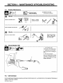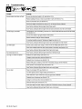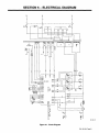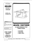
1
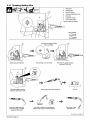
OM-iBO 424E
August
Miller
The Power OJIB&
1998
Processes
~
MIG
(GMAW) Welding
Flux Cored
(FCAW) Welding
Description
Arc
Welding Power Source
and Wire Feeder
Millermatic 400
p
Visit
ou~
webs~te at
Www~MllI~rWeIds.com
OWNERS
MANUAL
From Miller to You
Thank you and
you
can
get
congratulations on choosing Miller. Now
job done and get it done right. We know
have time to do it any other way.
you dont
Thats
the
why
when Niels Miller first started
building arc
sure
products offered
value
and
long-lasting
superior quality. Like you, his
customers couldnt afford anything less. Miller products
had to be more than the best they could be. They had to
be the best you could buy.
welders in 1929, he made
his
the
people that build and sell Miller products continue the
tradition. Theyre just as committed to providing equipment and service
that meets the high standards of quality and value established in 1929.
Today,
Working as bard asyondo
This Owners
Miller
help
Manual is
products.
you protect
designed help you get the most out of your
Please take time to read the Safety precautions. They will
to
yourself against potential
hazards
made installation and
warranty in the business
the worksite. Weve
and easy.
With Miller you can count on years of reliable
service with proper maintenance. And if for
~jjb((IIiIIIIJPr
IREGISTERED
IQUALITY
on
every
~ewer source from Miller is
backed by Ike:. młst flaisle1rie
SYSTEM
some reason
operation quick
the unit needs
______________
repair,
theres
a
section that will
Miller Is ibe first welding equipment
manufacturer in tbe U.S.A. to be
registered to ibe Iso 9001 quality
System Standard.
Troubleshooting
help you
figure out what the problem is. The parts list
will then help you to decide which exact part
you may need to fix the problem. Warranty and
service information for your particular model
are also provided.
Miller offers
a
Techrncal
Manuel which
provides.
more detailed service and
parts information for your
unit. lb obtain a .Tehnica!
Manual, canta~t your lOcal
distributor; Vour.distributor
can also supply you with
Welding Process :M~ua(s~.
suhasSMAW.t~TAW,
GMAW4 and GMAWP
Miller Electric manufactures
of welders and
welding
For information
products,
on
a
full line
related
other
equipment.
quality Miller
contact your local Miller distributor
to receive the latest full line
individual
catalog
or
sheets. To locate your nearest
distributor call 1-800-4-A-Miller.
catalog
~I/4.
ThePower~f.~
TABLE OF CONTENTS
The following term is
used interchangeably
throughout
this manual:
MIG=GMAW
SECTION 1
-
SAFETY PRECAUTIONS
-
READ BEFORE USING
1-4.
Symbol Usage
Arc Welding Hazards
Additional Symbols For Installation, Operation,
Principal Safety Standards
1-5.
EMF Information
1-1.
1-2.
1-3.
SECTION 1
1-1.
1-2.
1-3.
-
1
1
And Maintenance
-
Signification des symboles
Dangers relatifs au soudage a arc
Dangers supplØmentaires en relation
normes
1-5.
Information
sur
SECTION 2
2-1.
2-2.
2-3.
2-4.
2-5,
2-6.
2-7.
2-8.
2-9.
-
es
5
avec
Iinstallation,
8
champs Ølectromagnetiques
INSTALLATION
2-12.
Selecting a Location and Connecting Input
2-13. Threading Welding Wire
-
10
10
11
11
12
12
13
14
Power
OPERATION
MAINTENANCE &TROUBLESHOOTINQ
15
16
17
17
18
4-1.
Routine Maintenance
4-2.
Circuit Breaker CB1
18
4-3.
Unit Overload
18
4-4.
4-5.
Changing Drive Roll and Wire Inlet Guide
Aligning Drive Rolls and Wire Guide
19
4-6.
Troubleshooting
20
SECTION 5- ELECTRICAL DIAGRA~L
SECTION 6
-
WAR RANTY
OM-189424E
9
9
14
Controls
SECTION 4
8
9
2-11. Electrical Service Guide
-
le fonctionnement
7
de sØcuritØ
2-10. Inductance Selection
3-1.
5
5
Specifications
Duty Cycle And Overheating
Volt-Ampere Curve
Installing Work Clamp
Installing Welding Gun (Gun Not Included)
Setting Gun Polarity For Wire Type
IRemote 14 Receptacle
Installing Gas Supply
Installing Wire Spool and Adjusting Hub Tension
SECTION 3
3
LIRE AVANT UTILISATION
et Ia maintenance
Principales
3
4
CONSIGNES DE SECURITE
1-4.
1
PARTS LIST
18
19
21
22
SECTION 1
-
SAFETY PRECAUTIONS
-
READ BEFORE USING
som
Synibol Usage
1 1
Means
Warning! Watch Out! There are possible
hazards with this procedure! The possible hazards are
shown in the adjoining symbols.
4A
A
Marks
a
Arc
1-2
The
This group of
symbols means Warning! Watch Out! possible
ELECTRIC SHOCK, MOVING PARTS, and HOT PARTS hazards.
Consult symbols and related instructions below for necessary
actions to avoid the hazards.
special safety message.
ff7 Means Note~
A
not
safety
related.
Hazards
Welding
symbols
are used throughout this manual
identify possible hazards. When you
shown below
to call attention to and
symbol, watch out, and followthe related instructions
safety information given below is
seethe
to avoid the hazard. The
summary of the more complete safety information
found in the Safety Standards listed in Section 1 -4. Read and
follow all Safety Standards.
only
A
A
grounding of the workpiece
If earth
with
separate cable
a
Only qualified persons should install, operate, maintain,
repair this unit.
and
During operation, keep everybody, especially children, away.
use
is
required, ground
work
clamp
or
it
directly
work cable.
Do not touch electrode if you are in contact with the work,
or another electrode from a different machine.
ground,
Use
only well-maintained equipment. Repair or replace damaged
at once. Maintain unit according to manual.
parts
Wear
a
Keep
all
Clamp
safety
ELECTRICSHOCK
can
kilL,
harness if
and
panels
worktable
as near
Wear
hole-free
dry,
single
weld
and
AC output in damp areas, if movement is
danger of falling.
output
is
required,
required
for the
use remote
welding
output
confined,
or
before
install and
on
ground
this
equipment according
to its
Manual and national, state, and local codes.
-
making input connections,
conductor first
-
attach
proper
grounding
Do not
use
equipment
worn,
drape
when not in
over
work cable to any
your
body.
poorly spliced
be hazardous.
out of the fumes. Do not breathe the fumes.
If inside, ventilate the area and/or
remove welding fumes and gases.
If ventilation is poor,
use
exhaust at the
arc to
approved air-supplied respirator.
Safety Data Sheets (MSDS5) and the
manufacturers instructions for metals, consumables, coatings,
cleaners, and degreasers.
Read
the
use an
Material
a confined space only if it is well ventilated, or while
wearing an air-supplied respirator. Always have a trained watchperson nearby. Welding fumes and gases can displace air and
lower the oxygen level causing injury or death. Be sure the
breathing air is safe.
Do not weld in locations
cables.
near
degreasing, cleaning,
The heat and rays of the arc
toxic and irritating gases.
Do not weld
on
coated
plated steel,
weld area, the
or
can
fumes and gases. Breathing
these fumes and gases can be hazardous to your
health.
cadmium
use.
damaged, undersized,
cables
or
Welding produces
-
-
Do not
electrode
FUMESAND GASES
operations.
form highly
double-check connections.
Frequently inspect input power cord for damage or bare wiring
replace cord immediately if damaged bare wiring can kill.
Turn off all
one
Work in
Always verify the supply ground check and be sure that input
power cord ground wire is properly connected to ground terminal
in disconnect box or that cord plug is connected to a properly
grounded receptacle outlet.
When
than
touching any parts.
Keep your head
process.
control if present
Disconnect input power or stop engine before installing or
servicing this equipment. Lockout/tagout input power according
to OSHA 29 CFR 191 0.147 (see Safety Standards).
Properly
more
Turn Off inverter, disconnect input power, and discharge input
capacitors according to instructions in Maintenance Section
if
unit.
Owners
workpiece to prevent
body protection.
use
a
to
parts.
insulating gloves
Use AC output ONLY if
place.
good metal-to-metal contact to workpiece
the weld as practical.
SIGNIFICANT DC VOLTAGE exists after removal of
input power on inverters.
yourself from work and ground using dry insulating mats
or covers big enough to prevent any physical contact with the
work or ground.
there is
in
output terminal.
Insulate
Do not
securely
clamp when not connected
object.
Do not connect
electrical parts can cause fatal
shocks or severe burns. The electrode and work
circuit is electrically live whenever the output is on.
The input power circuit and machine internal
circuits are also live when power is on. In semiautomatic or
automatic wire welding, the wire, wire reel, drive roll housing, and all
metal parts touching the welding wire are electrically live. Incorrectly
installed or improperly grounded equipment is a hazard.
Do not touch live electrical
above floor level.
contact with any metal
live
Touching
working
covers
work cable with
Insulate work
If AC
do not
-
a
or
.
_nd_5/97
area
metals, such
unless the
can
as
coating
or
spraying
react with vapors to
galvanized, lead,
or
is removed from the
is well ventilated, and if necessary, while
wearing an air-supplied respirator. The coatings and any metals
containing these elements can give off toxic fumes if welded.
OM-189 424
Page
1
ARC RAYS
BUILDUP OF GAS
burn eyes and skin.
can
Shut off
Arc rays from the welding process produce intense
visible and invisible (ultraviolet and infrared) rays
that can burn eyes and skin. Sparks fly off from the
weld.
can
injure
shielding gas supply when
not in use.
Always ventilate confined spaces
approved air-supplied respirator.
a proper shade of filterto protect
your face and eyes when welding or watching (see ANSI Z49.i
and Z87.i listed in Safety Standards).
kilL
or
or
use
Wear a welding helmetfitted with
Wear
HOT PARTS
helmet.
Do not touch hot
Use
protective
glare; warn others
Wear
can cause severe
Allow
barriers to protect others from flash and
screens or
burns~
with side shields under your
approved safety glasses
bare handed.
parts
before
cooling period
working
on
or
gun
torch.
not to watch the arc.
protective clothing made from durable, flame-resistant
(leather and wool) and foot protection.
material
MAGNETIC FIELDS can affect pacemakers.
WELDING
cause fire
can
or
explosion.
Pacemaker
wearers
keep away.
Wearers should consult their doctor before
Welding
on
drums,
pipes,
closed containers, such as tanks,
can cause them to blowup. Sparks
can fly off from the welding arc. The flying sparks,
hot workpiece, and hot equipment can cause fires
and burns. Accidental contact of electrode to metal objects can
cause sparks, explosion, overheating, orfire. Check and be surethe
area is safe before doing any welding.
Protect
yourself
or
and others from
flying sparks
going near arc welding, gouging,
welding operations.
NOISE
can
flying sparks
can
Remove allflammables within 35ft
this is not
possible, tightly
strike flammable material.
(10.7 m)
them with
cover
of the welding arc.
approved covers.
that
aware
can cause
fire
Do not weld
on
welding
a
fire
closed containers such
as
Connect work cable to the work
unknown
Do not
prevent welding
paths
use
and
as
Wear
tip
approved
ear
protection
CYLINDERS
partition
causing
or
Shielding
pipes,
(see
can
explode
welding area as
traveling long, possibly
Protect
or
cut oft
welding
wire at
Remove any combustibles, such as
from your person before doing any
contain gas under
a
butane
lighter
or
matches,
Never
can
Injure
eyes.
drape
a
welding
torch
over a
or
Never allow
I
Never weld
S
only
shielding gas cylinders, regulators, hoses,
fittings designed for the specific application; maintain them
associated parts in good condition.
Use
a
welding
on a
electrode to touch any
pressurized cylinder
-
Keep protective cap in place
use or connected for use.
Read
cylinder.
explosion
will result.
correct
Turn face away from valve outlet when
approved safety glasses with side
shields even under your welding helmet.
other electrical circuits.
gas cylinder.
I
welding.
Welding, chipping, wire brushing, and grinding
cause sparks and flying metal. As welds cool,
they can throw off slag.
Wear
high
compressed gas cylinders from excessive heat,
slag, open flames, sparks, and arcs.
Keep cylinders away from any welding
protective garments such as leather gloves, heavy
shirt, cuffless trousers, high shoes, and a cap.
FLYING METAL
cylinders
gas
Install cylinders in an upright position by securing to a stationary
support or cylinder rack to prevent falling or tipping.
pipes.
when not in use.
2
damaged;
mechanical shocks,
electric shock and fire hazards.
welder to thaw frozen
Page
if
pressure. If damaged, a cylinder can explode.
Since gas cylinders are normally part of the welding
process, be sure to treat them carefully.
to AWS F4.1
Wear oil-free
OM-189 424
if noise level is
high.
close to the
current from
Remove stick electrode from holder
contact
or
tanks, drums,
they are properly prepared according
Safety Standards).
to
can
the hidden side.
on
unless
practical
equipment
extinguisher nearby.
ceiling, floor, bulkhead,
on a
or
If
welding sparks and hot materials from welding can
easily go through small cracks and openings to adjacent areas.
Be
processes
some
damage hearing.
Be alert that
Watch for fire, and keep
damage hearing.
and hot metal.
Noise from
Do not weld where
spot
or
over
and follow instructions
associated
Standards.
equipment,
valve
except
when
and
valve.
cylinder is in
compressed gas cylinders,
publication P-i listed in Safety
on
and CGA
opening cylinder
and
Additional
:1-3.
Symbols
For Installation,
And Maintenance
Operation,
FIRE OR EXPLOSION hazard.
Do not install
place
or
MOV!NGPARTS
unit on, over,
Do not install unit
Injury.
such
moving parts
as
all doors, panels, covers, and
closed and securely in place.
Keep
flammables.
fans.
guards
building wiring be sure power supply system
properly sized, rated, and protected to handle this unit.
Do not overload
is
near
from
Keep away
or near
combustible surfaces.
can cause
-
FALLiNG UNIT can cause
injury.
H.F. RADIATION
lifting eye to lift unit only, NOT running
gear, gas cylinders, or any other accessories.
Use equipment of adequate capacityto lift and
can cause
interference.
Use
High-frequency (H.F.) can interfere with radio
navigation, safety services, computers, and
communications equipment.
support unit.
only qualified persons familiar with
equipment perform this installation.
Have
If using lift forks to move unit, be sure forks are
long enough to extend beyond opposite side of
electronic
unit.
The
responsible
is
user
promptly
having a qualified electrician
problem resulting from the
for
correct any interference
installation.
OVERUSE an
Allow
cause OVERHEATING
cooling period;
Reduce current
starting
to weld
Do not block
STATIC
Put
or
follow rated
reduce
or
duty cycle.
duty cycle
boards
or
wrist
at once.
the FCC about
regularly
interference, stop using
the
checked and maintained.
Keep high-frequency source doors and panels tightly shut,
keep spark gaps at correct sethng, and use grounding and
shielding to minimize the possibility of interference.
again.
grounded
on
handling
by
Have the installation
before
filter airflow to unit.
(ESD) can damage PC
If notified
equipment
boards~
BEFORE
strap
parts.
ARC WELDING
static-proof bags and
store, move, or ship PC boards.
Use proper
can cause
interference.
boxes to
energy can interfere with
electronic equipment such as
Electromagnetic
sensitive
computers and computer-driven equipment
MOVING PARTS
can cause
such
injury.
Keep away from moving parts.
Keep away from pinch points
as
robots.
all equipment in the welding
electromagnetically compatible.
Be
such
as
To reduce
drive
possible,
rolls.
sure
WELDING WIRE
can cause
injury.
possible interference, keep weld cables as short as
together, and down low, such as on the floor.
Be
welding operation
equipment.
sure
according
Do not press gun
trigger
until instructed to do
is
close
Locate
tronic
area
this
welding
100 meters from any sensitive elec
machine
is installed
and
grounded
to this manual.
If interference still occurs, the user must take extra measures
as moving the welding machine, using shielded cables,
so.
such
point gun toward any part of the body,
people, or any metal when threading
welding wire.
using
Do not
line
filters,
or
shielding
the work
area.
other
Principal Safety
1 -&
Standards
Safety in Welding and Cutting, ANSI Standard Z49.1, from American
Welding Society, 550 N.W. LeJeune Rd, Miami FL 33126
Safety and Health Standards, OSHA 29 CFR 1910, from Superinten
dent of Documents, U.S. Government Printing Office, Washington,
D.C. 20402.
Recommended Safe Practices for the
Cutting
of Containers
Preparation
Welding
and
Held Hazardous Substances,
Standard AWS F4.1, from American
Welding Society
Welding Society, 550 N.W. LeJeune Rd, Miami,
American
for
That Have
FL 33126
Code, NFPA Standard 70, from National Fire
Protection Association, Batterymarch Park, Quincy, MA 02269.
National Electrical
Safe
Handling
of
Compressed Gases
in
Cylinders,
CGA
Pamphlet
P-i, from Compressed Gas Association, 1235 Jefferson Davis
Highway, Suite 501, Arlington, VA 22202.
Safety in Welding and Cutting, CSA Standard Wi 17.2, from
Canadian Standards Association, Standards Sates, 178 Rexdale
Boulevard, Rexdale, Ontario, Canada M9W 1 R3.
Code for
Safe Practices For
Occupation
And Educational
Eye
And Face
Protection, ANSI Standard Z87.1 ,from American National Standards
Institute, 1430 Broadway, New York, NY 10018.
Cutting And Welding Processes, NFPA Standard SiB, from National
Fire Protection Association, Batterymarch Park, Quincy, MA 02269.
OM-189 424
Page
3
EMF Information
1-5..
Considerations About Welding And The Effects Of Low
Electric And Magnetic Fields
Frequency
1.
Keep cables
Welding current, as it flows through welding cables, will cause electromagnetic fields. There has been and still is some concern about such
fields. However, after examining more than 500 studies spanning 17
years of research, a special blue ribbon committee of the National
Research Council concluded that: The body of evidence, in the
committees judgment, has not demonstrated that exposure to powerfrequency electric and magnetic fields is a human-health hazard.
However, studies are still going forth and evidence continues to be
2.
Arrange
3.
Do not coil
examined. Until the final conclusions of the research
may wish to minimize your exposure to
cutting.
To reduce magnetic
procedures:
welding
are
reached, you
electromagnetic
Page
4
cables to
or
together by twisting
one
taping
them.
side and away from the operator.
drape cables
Keep welding power
practical.
4.
or
source
around your
and cables
body.
as
far away from opera-
tor as
5.
Connect work clamp to
workpiece
as
close to the weld
as
possible.
fields when
About Pacemakers:
or
OM-189 424
close
fields
in
the
workplace,
use
the
following
Pacemakerwearersconsultyourdoctorfirst. If cleared byyourdoctor,
following the above procedures is recommended.
then
SECTION 1
-
CONSIGNES DE SECURITE
UTILISATION
LIRE AVANT
-
som
Signification
1-1
des
_nd_fre
5/97
symboles
Signifie Mise en garde! Soyez vigilant! Cette procedure
prØsente des risques de danger! Ceux-ci sont identifies
a
par des
A Identifie
un
symboles adjacents
aux
directives.
Ce groupe de symboles signifie Mise en garde ! Soyez vigilant II y a des
risques de danger relies aux CHOCS ELECTRIQUES, aux PIECES EN
message de sØcuritØ particulier.
MOUVEMENTetauxPIECESCHAUDES.
Reportez-vousauxsymboles
prendre pour
etauxdirectives ci-dessous afindeconnaltre les mesures
~
Signifie
1-2
A
NOTA
Øviter tout danger.
nest pas re/at/f a Ia sØcuritØ.
Dangers
relatifs au
soudage a
Iarc
Les symboles prØsentØs ci-aprŁs sont utilisØs tout au long du
present manuel pour attirer votre attention et identifier les
risques de danger. Lorsque vous voyez Un symbole, soyez
vigilant et suivez les directives mentionnØes aim dØviter tout
danger. Les consignes de sØcuritØ prØsentØes ci-aprŁs iie font
que rØsumer linformation contenue dans les normesde sØcuritØ
ØnumØrØes a Ia section 1 -4. VeuiHez lire et respecter toutes ces
normes
A
de sØcuritØ.
A
qu
des personnes
Au coursde lutilisation,tenirtoute
ticuliŁrement les enfants.
reparations
qualifiees.
et les
ne
doi
personnea lØcartet plus par
a
ce
un
Un
piŁces Łlectriques peut
circuits internes de lappareil sont Øgalement sous
tension a ce moment-l. En soudage semi-automatique ou automatique,
le fil, le dØvidoir, le logement des galets dentra~nement et les piŁces
mØtalliques en contact avec le hI de soudage sont sous tension. Des
matŁriels mal installŁs ou mal mis a Ia terre prØsentent un danger.
Ne
jamais
toucher les
harnais de sØcunitØ
Si lutilisation
se
dune
servir de
a
hauteur.
mis a
a
piece
pour Øviter le contact
ArrŒter les convertisseurs, dØbrancher le courant Ølectrique, et dØ
charger les condensateurs dalimentation selon es instructions
indiquŁes
dans Ia
partie
entretien avant de toucher
es
piŁces.
LES FUMEES:ET LES GAZ peuvent
Œtre dangereux.
Le soudage genŁre des fumØes et des gaz. Leur
inhalation peut Œtre dangereux pour votre sante.
source
Ølectrique courant electrique savŁre nØces
fonction de tØlØcommande si tappareil en est ØquipØ.
source
sØcuritØ).
lnstalleretmettrelaterre correctementcetappareil conformØment
manuel dutilisation et aux codes nationaux, provinciaux et
son
municipaux.
Toujours verifier Ia terre
Verifier et sassu
du cordon dalimentation
que le fil de terre du cordon dalimentation est bien raccordØ ala
borne deterre du sectionneur ou que lafiche du cordon est raccordØe
a une prise correctement mise a a terre.
-
rer
En eftectuant les raccordements dentrØe fixer dabord
le conducteur
approprie et contre-vŁnifier es connexions.
Verifier frequemment le cordon dalimentation pour voir sil nest pas
endommagŁ ou dØnudØ remplacerle cordon immØdiatementsilest
endommage un cable dŁnudŁ peut provoquer une electrocution.
Mettre Iappareil hors tension quand on ne lutilise pas.
Ne pas utiliser des cables uses, endommagØs, de grosseur insuffi
sante ou mal ØpissØs.
de mise a
en
piŁces Ølectriques sous tension.
protection secs ne comportant
Couper lalimentation ou arrŒterle moteur avant de procØderlinstal
lation, a Ia reparation ou ~ Ientretien de lappareil. DØverrouiller
Ialimentation selon Ia norme OSI-IA 29 CFR 1910.147 (voir normes
de
travaille
panneaux et capots.
ily a DU COURANT CONTINU IMPORTANT dans les
convertisseurs aprŁs Ia suppression de Ialimenta
tion Ølectrique.
electrique courant electrique dans es zones
humides, dans les endroits confines ou l oC~ on risque de tomber.
Se servir dune source electrique courant Ølectrique UNIQUEMENT si le
procØdØ de soudage le demande.
saire,
on
tous es
pince de masse quand pas
objet metallique.
de Ia piŁce et de a terre au moyen de tapis ou dautres
moyens isolants suftisamment grands pour empecher le contact phy
sique Øventuel avec Ia piŁce ou Ia terre.
servir de
quand
place
en
tout
Sisoler
se
Ia
soudure.
Porter des gants et des vŒtements de
pas de trous.
Ne pas
piŁce,
Fixer le cØble de retour de facon a obtenir un bon contact mØtal-mOtal
Ia piŁce a souder ou latable detravail, le plus prØs possible de Ia
ELECTRIQUE peut tuer.
contact avec des
simple
est en contact avec Ia
autre machine.
avec
Isoler Ia
provoquer une electrocution ou des blessures graves.
LØlectrode et le circuit de soudage sont sous tension
des que appareil est sur ON. Le circuit dentrØe et les
on
manuel.
Porter
avec
UN, CHOC
quand
provenant dune
Nutiliser quun materiel en bon Øtat. RØparer ou remplacer sur-le
champ les piŁcesendommagØes. Entretenirlappareilconformment
Maintenir solidement
Linstallation, lutllisation, lentretien
vent Œtre contiØs
Ne pas toucher electrode
terre ou une electrode
a terre
votre tŒte des fumŁes. Ne pas
les fumØes.
Eloigner
IintØrieur, ventiler Ia
respirer
un Øchappement au ni
des fumØes et des gaz de soudage.
Si Ia ventilation est insuffisante, utiliser un respirateur a alimenta
tion dam homologuØ.
A
veau
zone
etfou utiliser
de larc pour evacuation
Line es spØcif icationsde sØcuritØ des matØriaux (MSDSs) et les ins
tructions du fabnicant concernant les mŁtaux, les consommables,
les
revØtements,
les
nettoyants
et les
dØgraisseuns.
espace fermØ seulement slIest bien ventilØ ou
en portant Un respirateun a alimentation dam. Demander toujours a
un surveillant dOment formØ de se tenin a proximitØ. Des fumØes et
des gaz de soudage peuvent dØplacen lain et abaisser le niveau
doxygŁne provoquant des blessures ou des accidents montels.
Sassuner que lair de respiration ne prØsente aucun danger.
Travailler dans
un
Ne pas souderdans des endroits situØs a proximitØ dopØrations de
de nettoyage ou de pulvØrisation. La chaleur et les
degraissage,
rayons de larc peuvent
des gaz hautement
rØagir
toxiques
en
presence
de vapeuns et former
et irritants.
-
-
Ne pas enrouler es cables autour du corps.
Si Ia piŁce soudØe doitŒtre mise Ia terre, Iefairedirectementavecun
cable distinct ne pas utiliser le connecteur de piŁce ou le cable de
Ne pas souder des mØtaux munis dun revØtement, tels que lacier
cadmium a moms que le revŒte
ment nait ØtØ enlevØ dans Ia zone de soudure, que lendroit soit
galvanisØ, plaque en p10mb ou au
bien ventilØ, et si nŁcessaine, en portant un respirateur a alimenta
tion dam. Les revŒtements et tous Ies mØtaux renfermant ces ØlØ
ments
peuvent dŁgagen des fumŁes toxiques
en cas
de
soudage.
-
retour.
OM-189 424
Page
5
LES ACCUMULATIONS DE GAZ ris
LES RAVONS DE LARC peuvent pro
voquer des brlures dans les yeux et
sur Ia peau.
quent de provoquer des blessurØs
Le rayonnement de larc du procØdØ de soudage
genere des rayons visibles et invisibles intenses
(ultraviolets et infrarouges) susceptibles de provoquer
des bthlures dans
pendant le soudage.
yeux et
es
sur
Ia peau. Des Øtincelles sont
projetØes
ou
mŒme Ia mart.
Former lalimentation
non
Veiller
toujours a
bien aØrer les espaces confines
rateur dadduction
un casque de soudage muni dun Øcran de filtre appropriØ pour
proteger votre visage et vos yeux pendant le soudage ou pour regar
der (voir ANSI Z49.1 et Z87. 1 ØnumØrØ dans les normes de sØcuritØ).
du gaz
protecteur
en cas
de
utilisation.
ou se
servir dun
respi
homologuØ.
dair
Porter
Porter des
protections approuvØs pour les oreilles
PIECESCHAUDES peuvent
voquer des brlures graves;
DES
si le niveau sondre est
trop ØlevØ,
Utiliser des Øcrans
et de
ou
des barriŁres pour
garder
Øclair
proteger des tiers de
lØblouissement; demander aux autres personnes de
ne
pas
~
~-1
parties
No pas toucher des
re
arc.
chaudes a mains
nues
Porter des vŒtements do protection constituØ dans une matiŁre dura
ble, resistant au feu (cuir ou lame) et une protection des pieds.
m
pro
LE SOUDAGE peut provoquer
~ncendie ou une expIosion~
PrØvoir
une
dutiliser
le
pØriode
pistolet
ou
de refroidissement avant
Ia torche.
LES CHAMPS MAGNETIQUES peuvent
affecter les stimulateurs cardiaques.
soudage eftectuØ sur des conteneurs fermØs tels
que des reservoirs, tambours ou des conduites peut
provoquer leurØclatemerit. DesØt~ncelles peuvent Œtre
projetØes de Iarc de soudure. La projection dØtincel
lesdes piŁces chaudes et des Øquipements chauds petit provoquer des
Le
______
Porteursdestimulateurcardiaque, restezdistance.
stimulateur cardiaque doivent
Les porteurs dun
dabord consulter leur mØdecin avant do sapprocher
incendies et des brOlures. Le contact accidentel de electrode avec des
objets mØtalliques peut provoquer des Øtincelles, une explosion, un
surchauffement ou un incendie. Avant de commencer Ia soudage,
verifier et sassurer que lendroit no prØsente pas de danger.
So protØger et dautres
metal chaud.
personnes de Ia
projection
de
LE BRUIT petit affecter IouIe.
Le bruit des processus et des
louIe.
Porter des
SurveillertoutdØclenchementdincendie ettenirun extincteurproxi
mite.
un
sur un
plafond, plancher, paroi
incendie de lautre ctØ.
Brancher le cable stir Ia piŁCe 10 plus prŁs possible do Ia zone de sou
pour Øviter le transport du courant sur tine longue distance par
des chemins inconnus Øventuels en provoquant des risques dØlec
trocution et dincendie.
dage
Me pas utiliser le poste do
soudage pour degeler
des conduites ge
lees.
sous haute
manipuler
avec
precaution.
les boutoillos do gaz comprimØ dune chaleur excessive,
des chocs mØcaniques, du laitier, des flammes ouvertos, des Øtin
celles et des arcs.
ProtØger
Placer los bouteilles debout en los fixant dans un support station
ou dans tin porte-bouteilles pour los empŒcher de tomber ou
do so renverser.
naire
En cas de non utilisation, onlever Ia baguette dØlectrode
electrode ou couper le hI a a pointe de contact.
du
porte
protection dØpourvus dhuile tels quo des
gants en cuir, tine chemise en matØriau lourd, des pantalons sans re
Porter dos vØtements de
vers, des chaussures hautes et tin couvre chef.
vos
poches
DES PARTICULES VOLANTES
~
peuvent blesser les yeux.
desØtincellesetdesparticules metalliquesvolan
pØriode de refroidissement des soudures, ellos risquent
do projeter du laitier.
Porter des lunettes de sØcuritØ
Page
6
avec
Øcrans latØraux
Ne
es
bouteilles
Ølectriques.
jamais placer
ou Un
urte
Ne
eloignØes des circuits de soudage ou autros cir
tine
torche do
soudage
no
soudage stir tine bouteille a gal.
jamais entrer en contact avec
doit
bouteille.
jamais
souder
une
boutoille
pressurisØo
ØCran facial.
-
risque dexplosion.
Utiliser seulement des boutoillos de gaz protecteur, rØgulateurs,
tuyaux et raccords convenables pour ceflo application spØcifique;
los maintenir ainsi que los ØlØments associØs en bon etat.
Ne pas tenir Ia tŒte en face do Ia sortie
bouteille.
Le soudage, lØcaillement, le passage de Ia piŁce
a Ia brosse en fil de for, et le meulage genŁrent
tes. Pendant Ia
Tenir
cuits
Une electrode de
Avant do soudor, retirer toute substance combustible do
tellos quun allumeur au butane ou des allumettes.
OM-189 424
protections approuvØs pour los oreilles si
Des bouteilles de gaz protecteur contiennent du gaz
pression. Si une bouteille est endomma
gee, elle pout exploser. Dufaitquo los bouteilles do gaz
font normalement partie du procedØ do soudage, les
soudage sur des conteneurs fermØs tels quo des
reservoirs, tambours, ou conduites, a moms quils naient ete prepa
rØs correctement conformØment a AWS F4.l (voir los normes do
Me pas elfectuer le
sØcuritØ).
affecter
Si des BOUTEILLES sont endomma
gØes, elles pourront exploser.
separation
ou
Øquipoments pout
le niveau sondre est Irop ØlevØ.
Des Øtincelles ot des matØriaux chauds du soudage peuvent facile
ment passer dans dautres zones en traversant do petites fissures et
des ouvertures.
pout dØclencher
ou
peuvent tomber
DØplacer toutes es substances inflammables a une distance de 10,7
m de Iarc de soudage. En cas dimpossibilitØ
es recouvrir soigneuse
mont avec des protections homologues.
soudage eftectuØ
do gougeage
dØtincelles et do
Ne pas souder dans un endroit l oij des Øtincelles
sur des substances inflammables.
Le
operations do soudage a larc,
soudage par points.
des
en
ouvrant Ia soupape de Ia
Maintenir 10 chapeau de protection stir Ia soupapo, sauf
dutilisation ou do branchement do Ia bouteille.
en cas
Lire et suivre los instructions concernant Ies bouteilles de gaz corn
prime, los equipemonts associØs et los publications P-i CGA Ønu
mØrØes dans los normes do sØcuritØ.
1 -3.
Dangers supplØmentaires
en
relation
avec
linstallation,
le fonctionnØrnent
et Ia maintenance
Risque DJNCENDIE OU
DES
DEXPLOSION.
provoquer des blessures.
Ne pas placer lappareil sur, au-dessus
proximitØ de surfaces infilammables.
ou
a
ORGANES MOBILES
peuvent
Rester a lØcart des organes mobiles
ventilateur.
Maintenir fermŁs et fixement
lappareil a proximite de produits inflammables
NepassurchargerlinstallationØlectrique
sassurerquelalimen
Ne pas installer
panneaux,
recouvrements
en
et
comme
Ia
place les portes,
dispositifs de
-
tation est correctement dimensionnØ at
lappareil
en
protØgØ
protection.
avant de mettre
service.
LA CHUTE DE LAPPAREIL
blesser.
LE RAVONNEMENT HAUTE FRE
QUENCE (H.F.) risque de provoquer
des interferences.
peut
Le rayonnementhautefrequence peut provoquer
des interferences avec les Øquipements de ra
Utiliser lanrieau de levage uniquement pour sou
lever lappareil, NON PAS les chariot, las bouteil
les de gaz ou tout autre accessoire.
Utiliser un engiri dune
soulever lappareil.
capacitØ appropriØe
pour
En utilisarit des fourches de levage pour dØplacer lunitØ, sassurer
es fourches sontsuftisamment longues pour dØpasser du ctØ
oppose de lappareil.
que
LEMPLOI EXCESStF peut
SURCHAUFFER LEQUIPEMENT.
PrØvoir
une pØriode de refroidissement, respec
cycle opØratoire nominal.
IRØduire le courant ou Ia cycle operatoire avantde
recommancer Ia soudage.
dio-navigationetde communication, les services
de sŁcuritŁ et les ordinateurs.
Demander seulement a des personnes qualifiØas familiarisØes
avec des equipements Ølectroniquas de faire fonctionner linstalla
tion.
Lutilisateur est tenu de faire corriger rapidement par an Ølectricien
les interferences resultant de linstallation.
qualifie
Si le FCC
reil.
signafe des interferences, arrŒter immØdiatement lappa
Effectuer
regulierement
le contrle
et Jentretien
de installation.
Maintenir soigneusement fermØs les portes et es panneaux des
sources de haute frØquence, maintenir es Øclateurs a une distance
correcte et utiliser une terre et et un blindage pour rØduire las inter
fØrences Øventuelles.
ter le
Ne pas obstruer
es
LE: SOUDAGE A LARC
risque de
provoquer des interferences.
passages dair du poste.
LES CHARGES
ELECTROSTATIQUES
LØnergie
Ølectromagnetique
risque
de
provoquer des interferences pour lequipement
electronique sensible tel que las ordinateurs et
lequipement commandØ par ordinateur tel qua
peuvent endommager les circuits im
primes.
las robots.
Etablir
Ia connexion avec Ia barrette de terre
manipuler des cartes ou des piŁces.
Utiliser des pochettes et des boites antistatiques
pour stocker, dØplacer ou expŁdier des cartes de
circuits imprimes.
avant de
DES
ORGANES
MOBILES
peuvent
provoquer des blessures.
Me pas
sapprocher
des organes mobiles.
Ne pas sapprocher des points de coincement
tels que des rouleaux de commande.
LES FILS DE SOUDAGE peuvent pro
voquer des blessures.
lequipement de Ia zone de soudage soit com
patible ØlectromagnØtiquemant.
Pour rØduire Ia possibilite dintarfŁrence, maintenir les cables de
soudage aussi courts qua possible, las grouper, at les poser aussi
bas que possible (ex. par terre).
Veiller a souder a une distance de 100 metres de tout equipement
electronique sensible.
Veiller a ce qua ce poste de soudaga soit pose at mis a Ia terre
conformØment a ce mode damploi.
En cas dintertØrences aprŁs avoir pris las masures prŁcØdentes, II
incombe a lutilisateur de prendre des mesures supplØmantaires
telles que le dŁplacement du poste, lutilisation de cables blindØs,
lutilisation de filtres de ligna ou a pose de protecteurs dans Ia zone
Veiller ace que tout
de travail.
LES CHAMPS MAGNETIQUES peuvent
affecter Ies,stimulateurs cardiaques.
Portaurs de stimulataur
Ne pas appuyer sur Ia
racu linstruction.
Ne pas
sonnes
le fil de
le
gachette
avant den avoir
pistolet vers soi, dautres per
ou toute piŁce mØcanique en engageant
soudage.
diriger
cardiaque,
restaz a dis
tance.
Les porteurs dun stimulateur cardiaque doivent
dabord consultar lear mØdacin avant de sappro
char des operations de soudage a larc, de gou
geage
ou
de
soudage
par
points.
OM-189 424
Page
7
1-4.
Principales
normes
de sØcuritØ
Safety in Welding and Cutting, norme ANSI Z49. 1, de IAmerican
ding Society, 550 NW. Lejeune Rd, Miami FL 33126
Wel-
OSHA 29 CFR 1910, du Superintendent
Documents, U.S. Government Printing Office, Washington, D.C.
in
Cylinders, CGA Pamphlet
RŁgles de sØcuritØ en soudage,
coupage etprocØdØs connexes, norCSA Wi 17.2, de Association canadienne de normalisation, vente
de normes, 178 Rexdale Boulevard, Rexdale (Ontario) Canada M9W
1 R3.
me
20402.
Recommended Safe Practice for the
Preparation for Welding and Cut-
of Containers That Have Held Hazardous Substances, norme
AWS F4.1 de American Welding Society, 550 N.W. Lejeune Rd, Mia-
ting
,
mi FL 33126
National Electrical
Code, NFPA Standard 70, de Ia National Fire ProBatterymarch Park, Quincy, MA 02269.
tection Association,
1-5.
Handling of Compressed Gases
P-i, dela Compressed Gas Association, 1235 Jefferson Davis High
way, Suite 501, Arlington, VA 22202.
Safetyand Health Sandards,
of
Safe
Information
sur
les
Safe Practices ForOccupationAnd Educational EyeAnd Face Protec
tion, norme ANSI Z87.i, de lAmerican National Standards Institute,
1430 Broadway, New York, NY 10018.
Cutting and Welding Processes,
Protection Association,
DonnØes
Afin de rØduire
de travail,
sur le soudage Ølectrique et sur es effets, pour lorganisme,
champs magnØtiques basse frØquence
1
soudage, pendant son passage dans les cables de soudage, causera des champs electromagnØtiques. II y a eu et ii y a
encore un certain souci a propos de tels champs. Cependant, aprŁs
avoir examine plus de 500 etudes qui ont ØtØ faites pendant une pØnode de recherche de 17 ans, un comitØ special ruban bleu du
conclu: Laccumulation
de preuves,
champs ØlectromagnØtiques
Garder
es
cables ensembles en les torsadant
du ruban adhØsif.
Mettre tous les cables du ctØ
3
Ne pas courber pas et
votre corps.
~
Garder le poste de
de
dans Ienvironnement
ou en
es
avec
2
SU~
jugement du comitØ, na pas dØmontrØ que Iexposition aux
champs magnØtiques et champs Ølectriques a haute frØquence reprØ
sente un risque a Ia sante humaine.
Toutefois, des etudes sont
toujours en cours et es preuves continuent a Œtre examinØes. En at-
es
respecter Jes consignes suivantes
attachant
Le courant de
a
NFPA 51 B, de Ia National Fire
MA 02269.
champs ØlectromagnØtlques
des
National Research Council
norme
Batterymarch Park, Quincy,
ne
oppose
de
lopØrateur.
pas entourer pas es cables autour de
soudage
et
es
cables le plus loin possible
vous.
vant le
5
Relier Ia
pince
de
masse
le
plus prŁs possible de
Ia
zone
de
soudure.
Consignes relatives
aux
stimulateurs
cardiaques
tendant que les conclusions finales de Ia recherche soient Øtablies, ii
vous serait souhaitable de rØduire votre exposition aux champs Ølec-
Les personnes qui portent un stimulateur cardiaque doivent avanttout
consulter leur docteur. Si vous Œtes dØclarØ apte par votre docteur, II
tromagnØtiques pendant
est alons recommandØ de
OM-189 424
Page
8
le
soudage
ou
le coupage.
respecter
es
consignes
ci-dessus.
SECTION 2
Output
300 A at 32
Circuit Voltage
I
VDC,
60%
Duty Cycle
Wire
Type
-
2-2.
VDC,
230 V
Output,
50
or
60 Hz
I KVA
400 V
44.4
38
25.5
I
Wire Feed
17.9
I
Dimensions
Net
50-670 1PM
H: 37 in
275 lb
(1.2-1.7 m/min)
W: 19 in
(125 kg)
Speed
I
I
mm)
Stainless Steel
.023
(0.6
.035 in
-
-
0.9
mm)
Flux Cored
.030
(0.8
-
-
1/16
1.6
KW
112.7
I
and Diameter
1/16 in
1.6
240 A at 32
at Ra ted
1100% Duty Cycle
Solid Steel
-
Amps Input
Open
Max.
Rated
(0.6
INSTALLATION
Specifications
2-1.
.023
-
in
D:
mm)
(940 mm)
(483 mm)
30-1/4 in (768 mm)
Weight
Duty Cycle And Overheating
I
Duty Cycle
~H
is
percentage
of 10
minutes that unit can weld at rated
400
load without
g~
If
overheats, thermostat(s)
opens, output stops, and cooling
500
fan runs. Wait fifteen minutes for
unit to cool. Reduce amperage or
voltage, or duty cycle before
~0
z
overheating.
unit
zxj
welding.
A
150
Exceeding duty cycle can
damage unit and void
warranty.
100
10
15
30
40
5060708090100
%DUVfcYCLE
100%
Duty Cycle
At 240
Amperes
0*
Continuous
Welding
Overheating
OR
Reduce
Duty Cycle
Minutes
sdutyl 5/95 /
5A-1 87 478-A
OM-189 424
Page
9
2-3.
Curve
Volt-Ampere
1
Normal
The
volt-ampere
normal
Volt-Ampere Curves
curves show the
minimum and maximum
voltage and amperage output ca
pabilities of the welding power
source. Curves of other settings
fall between the
2
Overload
curves
shown.
Volt-Ampere
Curves
When unit is used
beyond capac
I
ity, circuitry
iI
and shuts down unit
senses
the overload
output. Re
lease
H
trigger and lower weld volt
age setting before trying to weld.
This shut down circuitry protects
internal circuits and parts from
overload damage.
20
tJ
I
0
I
I
113
0
I
I
I
~L5J
I
2~
I
I
2~G
I
I
313
I
3~C)
I
4(I)
EL AIVEEFES
ST-189 478
2-4.
Installing
OM-189 424
Page
10
Work
Clamp
2-5.
Installing Welding Gun (Gun
Not
Included)
1
Drive
2
Gun
3
Gun End
Assembly
Securing
Knob
Loosen
securing knob. Insert gun
through opening until it bot
drive assembly.
toms against
Tighten knob.
end
4
4
Gun
Trigger Plug
Insert
plug
tighten
threaded collar.
into
receptacle,
and
Close door.
3
Ret. ST-801 770
2-6.
Setting Gun Polarity
For Wire
Type
1
Shown As
Shipped Set For Electrode
Positive (DCEP) For Solid Steel Or
Aluminum Wires (GMAW Process).
-
Polarity Changeover Label
(Located Near Drive
Assembly)
Always
tures
read and follow manufac
recommended
polarity.
Wire Drive Assembly Lead
To Positive () Output Terminal
Work Clamp Lead To
Negative (-) Output Terminal
GUN POLARITY
CHANGEOVER CONNECTIONS
Reverse Lead Connections
-
For Electrode
Negative (DCEN) For Flux Cored Wires
(FCAW Process). Drive Assembly
Becomes
~=:~
Negative
S.144 449-0
3/4,11/l6in
OM-189 424
Page
11
2-7.
Remote 14
Receptacle
i~:i
f~
~
Socket*
REMOTE 14
Socket Information
A
24 volts
B
Contact closure to A
circuit.
G
Circuit
ac.
Protected
by circuit
breaker CB2.
OWPUT
(cONTACTOR)
completes
24 volts
ac
contactor control
010
common
for 24 and 115 volts
ac
circuits.
Ref. ST-152 973-A
*The
2-8.
remaining
sockets
are not
Installing
Gas
used.
Supply
Chain gas cylinder to running gear,
wall, or other stationary support so
cylinder cannot fall and break off
valve.
MOTE: All items listed below
customer
1
Regulator/Flow Gauge
Install
2
are
supplied.
so
face is vertical.
Gas Hose Connection
Obtain and connect gas hose of
proper size between regulator and
rear of machine.
Note: it may be necessary to install
supplied barbed Euro-adapter, into
Argon Gas
3
12
3
Flow
be
Adjust
flow rate is .57 cmh (cubic
meters per hour). Check wire man
flow
ufacturers
recommended
ORQ
rate.
4
CO2 Adapter
5
0-Ring
adapter with 0-ring between
regulator/flow gauge and CO2
cylinder.
Install
Ref.
Page
fitting on rear of machine,
connecting gas hose.
Typical
L
OM-189 424
gas
fore
2-9.
Installing
Wire
Spool
and
Adjusting Hub
Tension
OM-189 424
Page
13
2-10. Inductance Selection
Remove left side
panel.
Stabilizer Z
1
Tapped stabilizer
Z is
factory
nected to the stabilizer
suits most GMAW
Tools Needed:
~
Z
applications.
Stabilizer Z controls the induc
tance applied to the weld current.
To increase inductance and wet
3/8,7/l6in
~ZJiJ
con
tap which
puddle,
ending.
out the weld
stabilizer Z
3/8 in
To
change
connect to
inductance
proceed
as
follows:
2
Lead 24
3
Stabilizer Z
Tap
4
Stabilizer Z
Ending
5
Lead 25
To decrease inductance, connect
lead 25 to stabilizer tap and Secure.
Reinstall side
6
panel.
Weld Bead
Typical
Tap Stabilizer
Use the
The
Using
Connection
tap Stabilizer connection
with
welding
shielding gas.
when
CO2
100%
Use either stabilizer connection,
depending
ence, while
arc
upon your
welding
with
a
prefer
mixed
shielding gas.
Use stabilizer Z
ending
to weld on
stainless steel.
7
Typical Weld Bead Using
End High Stabilizer
The
Connection
Use the end Stabilizer connection
to reduce weld bead
spread
the weld
Install left side
H
crowning,
and
puddle.
panel.
II
Weld Bead
Using The Tap Stabilizer
Amps
Connection With 17 Volts, 100
Weld Bead
Using The End Stabilizer
Connection With 17 Volts, 100 Amps
Rel. 5T-148 265-B I Ref. ST.801 379-B
2-11. Electrical Service Guide
Input Voltage
Input Amperes
At Rated
Output
Max Recommended Standard Fuse Or Circuit Breaker
In Amperes
Mm
Input
Conductor Size In AWG/KcmiI
Max Recommended
Mm
Grounding
Input
Conductor
Page
Length
In Feet
Conductor Size In AWG/KcmiI
Reference: 1996 National Electrical Code
OM-189 424
Rating
14
(NEC)
(Meters)
230
400
44.4
25.5
70
40
8
10
128
8
(39)
259
10
(79)
Selecting
2-12.
a
Location and
Power
Connecting Input
Tools Needed:
~ 3/8
===z
c:I::::::1:=:=~lJ
3/8
in
in
GND/PE
GND/PE
Connect First
Size and ratings must comply with applicable
codes (see Section 2-11). Install conductors
in conduit or equivalent into a deenergized
line disconnect device.
400 VOLTS
230
VOLTS\
000000
Have
1
only qualified persons
Rating
Check
make this installation.
3
Jumper
Move
Label
input voltage
available at site.
Remove wrapper.
Links
jumper
links to match
input voltage.
Reinstall wrapper.
A
Special installation may be required where gasoline
volatile liquids are present
see NEC Article 511 or
or
-
2
Jumper Link
Label
CEC Section 20.
OM-189 424
Page
15
2-13.
Threadrng Welding Wire
1
Wire
2
Welding
3
Inlet Wire Guide
4
Pressure
5
Drive Roll
Spool
Wire
Adjustment
6
Outlet Wire Guide
7
Gun Conduit Cable
Lay
gun cable out
Knob
straight.
Tools Needed:
Open
pressure
assembly.
Push wire thru
Pull and hold wire; cut off end.
guides
into gun;
continue to hold wire.
-*
Close and
assembly,
Remove gun nozzle and contact
tighten pressure
and let go of wire.
1111
Press gun
trigger
until wire
out of gun. Reinstall
contact tip and nozzle
comes
Turn On.
II
Feed wire to check drive roll pressure.
knob enough to prevent slipping.
Tighten
tip.
Cut off wire. Close
and latch door.
Ref. ST.801 770 / S.0627.A
OM-189 424
Page
16
SECTION 3
3-1.
OPERATION
Controls
OM-189 424
Page
17
SECTION 4- MAINTENANCE &TROUBLESHOOTING
4-1.
Routine Maintenance
~
A
I
4-2.
Circuit Breaker CB1
4-3.
Unit Overload
If unit is used
trigger
OM-189 424
Page
18
Maintain
during
more
severe
often
conditions.
:
beyond capacity (excessive wire feed,
to reset this condition.
Disconnect power
before maintaining,
shorted output,
etc.),
wire feeds but is not
energized. Release gun
4-4.
Changing Drive Roll
and Wire Inlet Guide
NOTE: Drive rolls and inlet wire
not included. See
are
Table 6-1 for ordering informa
tion.
guide
1
Securing
2
Inlet Wire Guide
Loosen
drive
Screw
screw.
rolls
Slide tip
touching. Tighten
3
close to
screw.
Anti-Wear Guide
Install
4
as
possible without
as
guide
as
shown.
Drive Roll
Install correct drive roll for wire size
and
type.
5
Drive Roll
Turn nut
one
Securing
click to
Nut
secure
drive
roll.
Tools Needed:
~
5/64 in
t 7/l6in
ST-i 50!
4-5.
Aligning
Drive Rolls and Wire Guide
A
Turn Off power.
View is from top of drive rolls look
ing down with pressure assembly
open.
Correct
Incorrect
5
1
Drive Roll
2
Drive Roll
3
Wire Guide
4
Welding
5
Drive Gear
Securing
Nut
Wire
Insert screwdriver, and turn
screw
in or out until drive roll groove lines
up with wire guide.
Close pressure roll
assembly.
+
Tools Needed:
Ret. ST-800 412-A
OM-189 424
Page
19
4-6.
Troubleshooting
Remedy
Trouble
No weld
does not feed.
output; wire
Be
sure
line disconnect switch is On
line fuse
Replace building
Reset circuit breaker CB1
Secure gun
No weld
output; wire feeds.
trigger
(see
(see
Section 2-5, and
Factory Authorized Service Agent
Have
Factory
Authorized Service
Replace
clamp
contact
Agent
(overheating).
to
Low weld
Check
Fan motor does not
Low, high,
or
run.
erratic wire
speed.
links and correct
position
voltage (see Section 2-12).
if necessary
(see
Agent
check main control board.
Have
Factory
Authorized Service
Agent
check fan-on-demand circuit.
Check
Have
front
panel settings (see
to correct size drive rolls
drive roll pressure
inlet
guide,
position
Factory
of
contact
Turn Wire
(see
control to
Change
drive roll pressure
welding
Check gun
Have
trigger
Factory
wire
(see
liner if necessary
Agent
Section
tip
(see gun Owners
Manual).
check main control board.
4-2).
higher setting (see
or
liner
Section
3-1).
(see gun Owners
Manual).
(see Section 2-13).
to correct size drive rolls
Rethread
3-1).
(see Section 2-12).
links
Clear obstruction in gun contact
Readjust
2-12).
(see Section 4-4).
tip, and/or
Authorized Service
Speed
Section
Section
(see Section 2-13).
input jumper
Reset circuit breaker CB1
20
4-3).
check main control board and main rectifier.
check for low line
or
Section
Authorized Service
Replace
Page
trigger (see
Factory
Readjust
Manual).
check all board connections and main control board.
Have
Readjust
OM-1 89 424
gun Owners
to metal contact.
Agent
input voltage
input voltage jumper
Change
No wire feed.
see
tip (see gun Owners Manual).
Connect unit to proper
output.
2-12).
Allowfan to run; the thermostat will close when the unit has cooled
get good metal
Authorized Service
Factory
Section
check Power switch.
An overload condition occurred. Release gun
Have
(see
(see Section 4-2).
Have
Connect work
2-12).
reset circuit breaker if open
or
connections
Thermostat TP1 open
(see Section 2-2).
Section
Section
and leads.
Repair
Authorized Service
Section
(see
4-4).
2-13).
or
Agent
replace gun
if necessary
(see gun
check main control board.
Owners
Manual).
SECTION 5- ELECTRICAL DIAGRAM
SD-I 89 410
Figure
5-1. Circuit
Diagram
OM-189 424
Page
21
SECTION 6- PARTS LIST
Hardware is
common
and
not available unless listed.
a,
0
cJ
a,
/
(0
U-
/
/
/
U)
cJ
(I
(0
c~)
(0
LL
ci,
U-
(0
ST-802 104
Figure
OM-1 89424
Page
22
6-1. Main
Assembly
Item
No.
Dia.
Part
No
Mkgs.
Figure
1
..
PLG8
..
008072
Fig6-2
2
...3....T1
TP2
...189414
.
..163 266
4
Fig6-6
5
146165
6
089899
7
+146167
8
134464
9
+170513
Quantity
Description
6-1. Main
Assembly
HOUSING RECEPTACLE & SOCKETS
1
BAFFLE, center w/components
1
TRANSFORMER, pwr main
THERMOSTAT, NO
PANEL, rear w/components
1
PANEL,
LATCH,
PANEL,
LABEL,
1
1
side LH
1
slide flush mtg hole 1.000 wide
side
x
1.500
2
Ig
1
1
warning general precautionary
WRAPPER
CABLE, pwr
1
1 2ft
1
8ga 4/c
10
187804
11
185541 ...BASE
1
12
186758 ...WHEEL
2
052692
1
121 614
2
AXLE, running gear (consisting of)
RING, retaining ext .750 shaft x .O85grv depth
...14... SR1...185555
RECTIFIER, SCR main (consisting of)
C7-12
031 689.... CAPACITOR, rectifier
185830.... THYRISTOR, SCR568A400V
SCR1-3
TP3
171 600
THERMOSTAT, NC
13
.
1
6
.
3
.
...
PLG2
..
D4-6
..
D7,8
..
...15.
CONNECTOR & SOCKETS
1
3
DIODE, rect45OA200V
037 956.... DIODE, rect 275A 300V
008 999
CASTER, plstc swvl 4 in dia
6-4
PANEL, front w/components
Fig
185831
....
2
2
1
...
Zi
...
187 998
...
130 750
...
600 320
+When
....
...
...16.
...17.
1
....
115 093
ordering
a
..
.
1
STABILIZER
CLAMP, ground 350A
CABLE, weld cop strd No.
component originally displaying
a
1
1
lOft
(order by ft)
precautionary label, the
label should also be ordered.
To maintain the factory original performance of your equipment, use only Manufacturers
Suggested
Replacement Parts. Model and serial number required when ordering parts from your local distributor.
OM-1 89 424
Page
23
Hardware is common and
not available unless listed.
/
/
0
0)
Co
0)
CO
0
C
(0
C
C~)
cJ
C\j
C
CJ
U
Co
U-
ST-8O1 952-A
Figure
OM-1 89 424
Page
24
6-2.
Baffle, Center w/Components
Item
No.
Dia.
Part
No.
Mkgs.
Description
Figure
.058427
.2
085 980
.605941
186437
057 971
057 745
.7
186435
.8
186436
177307
10
.188710
184965
11
186998
.12
082 902
.13
185643
083 147
14.... C6
...
184584
187752
15... TEl
...
16
189409
038618
.17... PCi ...184331
PLG3
PLG4
PLG6
18.... R5
19...
C3,5
20... NEG
.21
...
POS
6-2.
Quantity
Baffle, Center w/Components (Fig 6-1 Item 2)
RING, retaining spool
NUT, stl hex full .625-11
WASHER, flat stl .640 ID x 1.000 OD x 1 4ga thk
SPRING, cprsn .845ODx.ll0wirexl.500
WASHER, flat stl keyed 1.500diax .l25thk
SPRING, cprsn 2.430 OD x .090 wire x 2.500
HUB, spool
WASHER, brake
REEL, support
BAFFLE, center, (consisting of)
COVER, primary board hole
CAPACITOR ASSEMBLY KIT, (consisting of)
STRIP, mtg center capacitor
STRIP, mtg capacitors
GROMMET, scr No. 8/10 panel hole .312sq .500 high
CAPACITOR, elctlt 1 5000uf 45VDC
INSULATOR, capacitor
TERMINAL ASSEMBLY, pri 3ph two voltage
LINK, jumper term bd pri
CIRCUIT CARD, control main
1
1
1
1
1
1
1
1
1
1
1
1
1
2
6
8
1
1
3
1
..
131 052
HOUSING RECEPTACLE & SOCKETS
1
..
131 056
1
..
115092
...
119998
HOUSING RECEPTACLE & SOCKETS
HOUSING PLUG & SOCKETS
RESISTOR, WW fxd 300W 5 ohm
..
128750
CAPACITOR
2
..
097416
TERMINAL, pwr output black
TERMINAL, pwr output red
BUSS BAR, shunt
SHUNT, meter 50V 400A
TERMINAL, frict male .250 x .032 3 pair
COVER, cable
CIRCUIT BREAKER, man reset 1 P 5A 25OVAC
STAND-OFF SUPPORT, PC card
1
.
.097421
185850
141 567
22
129524
...23
071971
25.CB1,CB2
180912
26
134201
...27
Fig6-5
1
1
1
1
1
1
1
2
4
WIRE DRIVE & GEARS
1
+When ordering a component originally displaying a precautionary label, the label should also be ordered.
To maintain the factory original performance of your equipment, use only Manufacturers
Suggested
Replacement Parts. Model and serial number required when ordering parts from your local distributor.
OM-1 89 424
Page
25
Dia.
Item
No.
Part
No.
Mkgs.
Figure
.
3
.
..
R2,3
2
LEAD ASSEMBLY, elect
LEAD ASSEMBLY, elect
1
Cl
185 890
....
C2
185896..
5
..
148 240
..
..
186473..
51
128 756..
....
RC5
048 282..
....
RC1
143 976..
7
....
8
9
10
186470..
11
186 472
12.... PL1
157 958
13
097 924
Hardware is
common
16)
POTENTIOMETER
..
....
C13-15
6-1 Item
035897..
..
4
6
Panel, Front w/Components (Fig
1
189 350
2
6-3.
PANEL, front control
LABEL, nameplate
+188 711
1
Quantity
Description
..
..
..
1
1
3
CAPACITOR, cer disc .OO3uf 2000VAC
PANEL,front
SWITCH, tgl 3PST 40A 600VAC
RECEPTACLE w/SOCKETS
RECEPTACLE w/SOCKETS
PANEL, logo
PANEL, louver
LIGHT, md white lens 28V
KNOB, pointer 1 .625dia x .250 ID
1
1
1
1
1
1
1
2
and
not available unless listed.
13
12
11
ST-801 953
Figure
6-3.
Panel, Front w/Components
To maintain the factory original performance of your equipment, use only Manufacturers
Suggested
Replacement Parts. Model and serial number required when ordering parts from your local distributor.
OM-189 424
Page
26
Item
No.
Dia.
Part
No.
Mkgs.
Figure
6-4. Wire Drive And Gears
602 009
172 075
3
166072
4
010224...PIN,springCS.187x1.000
182 788
HOUSING, adapter gun/feeder
5
...
...
6-2 Item
27)
1
1
1
1
1
...
FASTENER, pinned
WASHER, cupped stl .328 ID x .812 OD x .125 lip
SPRING, cprsn .770 OD x .105 wire x 1.225
085 243
KNOB, adj tension
166 071
LEVER, mtg pressure gear
079634
PIN, hinge
151 828... PIN, cotter hair .054 x .750
173 616
COVER, right angle motor
173 435
MOTOR, gear 24VDC 122RPM 20:1 ratio
079 633
FITTING, hose brs barbed M 3/l6tbg
085 242
085 244
010 231
6
7
8
9
10
11
...
1
.
1
.
.
...
1
...
1
...
1
1
...
12
13
14
...
(Fig
SCREW, .250-20 x 1.25 soc hd gr 8
CARRIER, drive roll w/components
SPACER, gear
2
1
Quantity
Description
PM
15
16
18
19
20
.21
22
23
...
2
...
1
...
1
1
...
601 966...SCREW, .375-16x1.25hexhd
604 538
WASHER, flat stl SAE .312
124 778
KNOB, plstc T 1.000 Ig x .312-18 x 2.000 bar
173 619
CARRIER, drive roll w/components
3
1
.
..
...
1
...
1
174609...SCREW,M4-.7x12
174610... SCREW, M6-1.Ox20sochd
192 029
WASHER, fIat .250 ID x .437 OD
173620... BUSHING, motormtg
*045 233
GUIDE, anti-wear
.
...24
1
3
3
3
1
..
...
See Table 6-1
Drive Roll & Wire Guide Kits.
~ Hardware is
common
13
and
not available unless listed.
5
3
16
21
)
20
1
18
Figure
*Recommended
Spare
ST-148529-E
6-4. Wire Drive And Gears
Parts.
To maintain the factory original performance of your equipment, use only Manufacturers Suggested
Replacement Parts. Model and serial number required when ordering parts from your local distributor.
OM-189 424
Page
27
Table 6-1. Drive Roll And Wire Guide Kits
NoteL~
Base selection of drive rolls upon the
following
recommended usages:
1
V-Grooved rolls for hard wire.
2
U-Grooved rolls for soft and soft shelled cored wires.
rolls for
soft shelled wires
3
U-Cogged
4
V-Knurled rolls for hard shelled cored wires.
5
extremely
Drive roll
with
types may
U-Grooved).
be mixed to suit
(usually
hard
surfacing types).
particular requirements (example: V-Knurled
Wire Diameter
Drive Roll
Inlet
Wire Guide
Kit No.
Fraction
Decimal
Metric
.023/.025 in.
.023/.025 in.
0.6mm
.030 in.
.030 in.
0.8
.035 in.
.035 in.
.045 in.
roll in combination
Part No.
Type
087 131
087 130
V-Grooved
056 192
mm
079 594
053 695
V-Grooved
056 192
0.9
mm
079 595
053 700
V-Grooved
056 192
.045 in.
1.2
mm
079 596
053 697
V-Grooved
056 193
.052 in.
.052
1.3
mm
079597
053698
V-Grooved
056193
1/16 in.
.062
1.6mm
079 598
053 699
V-Grooved
056 195
Ret. S-0026-B/7-91
Item
No.
Dia.
Part
No.
Mkgs.
Quantity
Description
Figure
6-5.
Panel, Rear wlComponents (Fig
6-1 Item
4)
...3...FM1. ..148 808
NUT, speed push-on-type .312 stud .625 OD
BLADE, fan 9 in 5wg 34deg .309 bore CCW
MOTOR, fan 230V 1550RPM .3l2dia shaft
..188 709
...5...GS1. ..125 785
WINDTUNNEL
VALVE, 24VAC 2 way custom port 1/8 ort
1
PANEL, rear
BRACKET~ support tank
CHAIN, weldless 2/0 x 27.000 Ig
NU1~ nyl hex jam .75ONPST
CONNECTOR, clamp cable .690/1.070
1
049 399
.2
..148 809
.143810
169654
602 387
.7
605 227
178126
fT Hardware is
common
x
.456 ID
1
1
1
1
and
not available unless listed.
5T~8O1 954-A
Figure
To maintain the
Replacement
OM-189 424
Page
6-5.
factory original performance of your equipment, use only Manufacturers Suggested
required when ordering parts from your local distributor.
Parts. Model and serial number
28
Panel, Rear w/Components
:pStscanbeinyour
EffectIve January 1, 1998
(Equipment with a seriai number pretace of it
Warranty Questions2
Call
1-800-4-A-MILLER
.
ioryoir Scat:,
~: Miller distributor.
~Your distributor
also
gives
::.senn~
You
always:get
the fast:
reIi~le resportse yOu :
need; Most replacement
hahds. in 24 Pours,
:~Uppofl. ~..
Ne~l
~ ansWers to the..
tOugh welding questions?.
Contact. yoUr distributor.
The.:spenjse.ofthe
~.distributar and Miller is~
help yoU,
:::.step.otthe.way...
thereto
This limited
warranty supersedes
guarantees
all
previous
or
warranties
LIMITED WARRANTY
Subject to the terms and conditions
below, Miller Electric Mtg. Co., Appleton, Wisconsin,
warrants to its original retail purchaser that new Miller
equipment sold after the effective date otthis limited warranty
is free of defects in material end workmanship at the time it is
shipped by Miller. THIS WARRANTY IS EXPRESSLY IN
LIEU OF ALL OTHER WARRANTIES, EXPRESS OR
THE
INCLUDING
WARRANTIES
OF
IMPLIED,
MERCHANTABILITY AND FITNESS.
Miller warranties and is exclusive with
expressed
*
notified in
writing
within
thirty (30) days
of such defect
failure, at which time Miller will provide instructions
warranty claim procedures to be followed.
Spoolmate
Millers
1.
such
2.
3.
International distributor.
*
Inverters
3 Years Labor
-
*
Plasma Arc
*
Semi-Automatic and Automatic Wire Feeders
*
Inverter Power
*
Intellitig
*
Engine Driven Welding Generators
(NOTE: Engines are warranted separately by
engine manufacturer.)
1 Year
Power Sources
Cutting
Supplies
the
Parts and Labor
Consumable components; such as contact tips, cuffing
nozzles, conteclors, brushes, slip rings, relays or parts
Equipment
by any party other
equipment that has been improperly
installed, improperly operated or misused based upon
industry standards, or equipment which has not had
reasonable and necessary maintenance, or equipment
which has been used for operation outside of the
specifications for the equipment.
or
*
Positioners end Controllers
Automatic Motion Devices
*
Robots
*
IHPS Power Sources
*
Water Coolant
*
HF Units
*
Grids
*
Spot
*
Load Banks
*
SDX Transformers
*
Miller
*
Running Gear/Trailers
*
Plasma
of
Spoolmate 185)
ANY EXPRESS WARRANTY NOT PROVIDED HEREIN
AND ANY
IMPLIED
WARRANTY, GUARANTY OR
REPRESENTATION AS TO PERFORMANCE, AND ANY
REMEDY FOR BREACH OF CONTRACT TORT OR ANY
OTHER LEGAL THEORY WHICH, BUT FOR THIS
MIGHT
ARISE
BY
PROVISION,
IMPLICATION,
OPERATION OF LAW, CUSTOM OF TRADE OR COURSE
OF DEALING, INCLUDING ANY IMPUED WARRANTY OF
MERCHANTABILITY OR FITNESS FOR PARTICULAR
WITH
RESPECT
TO ANY
AND
ALL
PURPOSE,
EQUIPMENT FURNISHED BY MILLER IS EXCLUDED
AND DISCLAIMED BY MILLER.
Welders
Cyclomatic Equipment
Cuffing Torches
PLAZCUT Models)
(except APT, ZIPCUT &
*
Deutz
*
Options
(NOTE: Field options are covered under True Bluefi
for the remaining warranty period of the product they
North
America)
Field
installed in,
or
for
a
greater.)
TO THE EXTENT PERMITTED BY LAW, THE REMEDIES
PROVIDED HEREIN ARE THE SOLE AND EXCLUSIVE
REMEDIES. IN NO EVENT SHALL MILLER BE LIABLE
FOR DIRECT, INDIRECT, SPECIAL, INCIDENTAL OR
CONSEQUENTIAL DAMAGES (INCLUDING LOSS OF
PROFIT), WHETHER BASED ON CONTRACT, TORT OR
ANY OTHER LEGAL THEORY.
Systems
Engines (outside
by this werrenty, the
option: (1) repair; or
(2) replacement; or, where authorized in writing by Miller in
appropriate cases, (3) the reasonable cost of repair or
replacement at an authorized Miller service station; or (4)
payment of or credit for the purchese price (less reasonable
depreciation based upon actual use) upon return of the
goods at customers risk end expense. Millers option of
repair or replacement will be FOB., Factory at Appleton,
Wisconsin, or FOB. ate Miller euthorized service facility as
determined by Miller. Therefore no compensation or
reimbursement for transportetion costs of eny kind will be
minimum of
one
year
Some states inthe U.S.A. do not allow limitations of how long
en implied warranty lasts, or the exclusion of incidental,
indirect, special or consequential damages, so the above
limitetion or exclusion may not apply to you. This warranty
provides specific Ieget rights, and other rights may be
available, but may very from state to state,
In
Ceneda, legisletion
additional
herein,
T/wlbwerofBkte.
that has been modified
allowed.
(w/exception
*
whichever is
V
are
In the event of e warranty claim covered
exclusive remedies shell be, at Millers
Transformer/Rectifier Power Sources
Process Controllers
U
to:
by others,
Parts and Labor
3 Years
4.
6 Months
5.
90
*
apply
AND USE BY COMMERCIALIINDUSTRIAL USERS AND
PERSONS TRAINED AND EXPERIENCED IN THE USE
AND MAINTENANCE OF WELDING EQUIPMENT.
(input end output rectifiers only)
Motor Driven Guns
IA.
shell not
but manufactured
MILLER PRODUCTS ARE INTENDED FOR PURCHASE
main power rectifiers
*
are
Warranty
by Miller,
engines ortrsde accessories. These items
by the manufacturers warranty, if any.
then Miller,
year after the equipment is sent to a North American
distributor or eighteen months after the equipment is sent to
Original
as
(No labor)
that fail due to normal wear.
or one
*
True Bluefi Limited
Items furnished
covered
time periods. All warranty time periods start on the date that
the equipment was delivered to the original retail purchaser,
5 Years Parts
Parts
t 85
or
3.
every
Kits
Replacement
Miller shall honor warranty claims on warranted equipment
listed below in the event of such a failure within the warranty
1.
other
Remote Controls
Accessory
2.
en
no
implied.
Torches
*
the
on
or
APT, ZIPCUT & PLAZCUT Model Plasma Cutting
-
Within the warranty periods listed below, Miller will repair or
replace eny warranted parts or components that fail due to
such defects in material or workmanship. Miller must be
newer)
or
Days
Batteries
Parts and Labor
MIG Guns/TIG Torches
warranties
in
some
or
provinces provides for certain
remedies other than
es
steled
they mey not be waived, the
limitations and exclusions set out ebove may not epply. This
Limited Warranty provides specific legal rights, and other
rights may be eveilebte, but may vary from province to
end to the extent that
province.
miller_werr we
Owners Record
Please complete and retain with your personal records.
Model Name
Serial/Style Number
Purchase Date
(Date
which
equipment
was
delivered to
original customer.)
Distributor
Address
City
State
lip
Resources Available
Always provide Model Name and Serial/Style Number.
Contact your Distributor for:
To locate distributor nearest you call
1-800-4-A-Miller.
Welding Supplies
Options
and Consumables
and Accessories
Personal
Safety Equipment
Service and
Repair
Miller Electnc
Replacement Parts
International
and
(Servicing
Co
CÆmpaæy
1635 West Spencer Street
Appleton WI 54914 USA
Training (Schools, Videos, Books)
Technical Manuals
Mtg
M Illtnois Tool Works
Information
Headquarters-USA
Phone; 920~35~4505
:
USA &Canada FAX: 920L73&4134
Parts)
lntemattonal F~4X 920 735-4125
Circuit
Diagrams
European Headquarters
Welding Process Handbooks
Phone: 44 (0)1204593493
FAX: 44 (0) 1204598966
www
Contact the DeliveriuD Carrier br:
File
a
claim for loss
or
-
UnitedKingdom
MillerWelds
corn
damage during
shipment.
For assistance in
filing
contact your distributor
manufacturers
PRINTED IN USA
settling claims,
and/or equipment
or
Transportation Department.
'
The Thwer jlikw
1998 Miller Electric
Mfg.
Co.
5/98