1
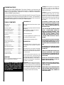
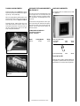
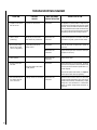
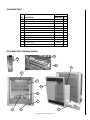
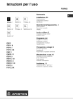
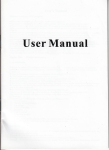
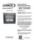
INSTALLATION INSTRUCTIONS
AND HOMEOWNER'S MANUAL
MERIT® PLUS SERIES
27" Electric Fireplace
P/N 850,035M REV. A 10/2006
MODELS
MPE-27
This manual will enable you to obtain a safe, efficient and dependable
installation of your electric fireplace. Please read and understand these
instructions before beginning your installation.
Do not alter or modify the fireplace or its components under any
circumstances. Any modification or alteration of the fireplace system,
including but not limited to the fireplace and accessories, may void the
warranty, listings and approvals of this system and could result in an
unsafe and potentially dangerous installation.
INSTALLER: DO NOT DISCARD THIS MANUAL
PLEASE LEAVE FOR THE HOMEOWNER
FOR YOUR SAFETY
DO NOT STORE OR USE GASOLINE OR OTHER FLAMMABLE VAPORS AND LIQUIDS IN THE VICINITY OF THIS
OR ANY OTHER APPLIANCE
RETAIN THESE INSTRUCTIONS
FOR FUTURE REFERENCE
A French manual is available upon request. Order Form Number
850,035CF.
Ce manuel d’installation est disponible en francais, simplement en
faire la demande. Numéro de la pièce 850,035CF.
®
C
NOTE: DIAGRAMS & ILLUSTRATIONS NOT TO SCALE.
CSA Report No. 46-M198
US
1
CONGRATULATIONS!
In selecting this DAVE LENNOX Merit® Plus electric fireplace, you have chosen the
finest and most dependable fireplace found anywhere. A beautiful and prestigious
addition to the finest homes. Welcome to a Family of hundreds of thousands of
satisfied LENNOX Fireplace Owners.
Please read and carefully follow all of the instructions found in this manual. Please pay
special attention to the safety instructions provided in this manual. The Homeowner's
Care and Operation Instructions included here will assure that you have many years of
dependable and enjoyable service from your LENNOX product.
PACKAGING LIST
TABLE OF CONTENTS
Packaging List ................................. Page
2
Introduction ..................................... Page
2
Locating Fireplace ............................ Page
3
Tools/Supplies Required .................. Page
3
Framing Specifications .................... Page
4
Fireplace Specifications ................... Page
4
Clearances ....................................... Page
5
Pre-installation ................................ Page
5
Final Finishing .................................. Page
5
Operating Instructions ..................... Page
6
Remote Control Operation ............... Page
6
Back Glass ....................................... Page
7
Bulb Replacement ............................ Page
7
Flame Generation Bulbs ................... Page
8
Placing Glowing Embers .................. Page
9
Optional Accessories ....................... Page
9
Troubleshooting ............................... Page 10
This assembled Electric Room Heater is packaged with:
• One accessory package located in the firebox,
containing;
1. One Installation and Operation Manual.
2. One Warranty Certificate.
• One Remote Control
• Two spare Light Bulbs are located in a recess
on the back of the log assembly.
• One bag of orange glowing embers.
INTRODUCTION
This Electric Fireplace is designed for residential applications to be framed in used freestanding.
This appliance has been tested in accordance
with UL 2021 and CSA C22.2 No. 46-M198
standards for fixed and location dedicated electric room heaters.
Replacement Parts .......................... Page 11
IMPORTANT
Please read and understand these instructions
before beginning your installation.
WARNING: IF THE INFORMATION IN
THIS MANUAL IS NOT FOLLOWED
EXACTLY, AN ELECTRICAL SHOCK OR
FIRE MAY RESULT CAUSING PROPERTY DAMAGE, PERSONAL INJURY
OR LOSS OF LIFE.
2
Installation must conform to local codes. In the
absence of local codes, electrical wiring and
grounding must comply with the National Electrical Code ANSI/ NFPA 70 - latest edition. In
Canada, the current CSA C22-1 Canadian Electrical Code - latest edition.
IMPORTANT: Before starting your fireplace installation, read this installation and operation
manual very carefully to ensure you understand
it completely and in entirety. Failure to follow
these instructions may result in a possible
electric shock, fire hazard and/or injury or property damage and will void the warranty.
NOTE: DIAGRAMS & ILLUSTRATIONS NOT TO SCALE.
CAUTION: Extreme caution is necessary when
any heater is used by or near children or
invalids and whenever the heater is left operating and unattended.
CAUTION: This appliance is mounted on rubber
feet. The purpose of these feet is to ensure
adequate air circulation beneath the fireplace.
Do not remove these feet. Do not install the
fireplace directly onto a carpet, rug, furniture or
similar surfaces, which could hinder or block
the airflow.
TO PREVENT A POSSIBLE FIRE, DO NOT
BLOCK AIR INTAKES OR EXHAUSTS IN ANY
WAY. DO NOT USE NEAR SOFT SURFACES,
LIKE A PILLOW, WHERE OPENINGS MAY
BECOME BLOCKED.
THIS APPLIANCE MAY BECOME HOT WHEN
IN USE. TO AVOID BURNS, DO NOT LET
BARE SKIN TOUCH HOT SURFACES. KEEP
COMBUSTIBLE MATERIALS, SUCH AS FURNITURE, PILLOWS, BEDDING, PAPERS,
CLOTHES AND CURTAINS AT LEAST 3 FEET
(1 METER) FROM THE FRONT OF THIS APPLIANCE.
DO NOT OPERATE ANY HEATER WITH DAMAGED WIRING OR CONNECTORS, OR AFTER
THE APPLIANCE MALFUNCTIONS, OR IF IT
HAS BEEN DROPPED OR DAMAGED IN ANY
WAY.
ANY REPAIRS TO THIS FIREPLACE SHOULD
BE PERFORMED BY A QUALIFIED SERVICE
TECHNICIAN.
UNDER NO CIRCUMSTANCES SHOULD THIS
FIREPLACE BE MODIFIED. PARTS HAVING
TO BE REMOVED FOR SERVICING MUST BE
REPLACED PRIOR TO OPERATING THE FIREPLACE AGAIN.
DO NOT USE THIS APPLIANCE OUTDOORS.
DO NOT EXPOSE FIREPLACE TO THE ELEMENTS (SUCH AS RAIN, ETC.).
NEVER LOCATE THIS APPLIANCE WHERE IT
COULD FALL INTO A BATHTUB OR OTHER
WATER CONTAINER.
DO NOT RUN ELECTRICAL WIRING OR POWER
CORD (OPTIONAL) UNDER CARPETING. OR
COVER WITH THROW RUGS, RUNNERS OR
SIMILAR MATERIALS.
AVOID THE USE OF AN EXTENSION CORD
BECAUSE THE EXTENSION CORD MAY
OVERHEAT AND CAUSE A RISK OF FIRE.
HOWEVER, IF YOU HAVE TO USE AN EXTENSION CORD, THE CORD SHALL BE NO.
14 AWG MINIMUM SIZE AND RATED NOT
LESS THAN 1800 WATTS, 15 AMPS. THE
EXTENSION CORD MUST BE A THREE WIRE
CORD WITH GROUNDING TYPE PLUG AND
CORD CONNECTION.
THIS APPLIANCE HAS HOT AND ARCING OR
SPARKING PARTS INSIDE. DO NOT USE IT IN
AREAS WHERE GASOLINE, PAINT OR FLAMMABLE LIQUIDS ARE USED OR STORED.
LOCATING YOUR MERIT PLUS ELECTRIC
FIREPLACE
TOOLS AND BUILDING SUPPLIES
NORMALLY REQUIRED
Your new fireplace may be installed into existing framing or built into a wall (see Figure 1), or
set in a freestanding mantel cabinet available
from your dealer (see Page 9).
No tools are required for setup of the fireplace.
When choosing a location for your new fireplace, ensure that the general instructions are
followed. Also, for the best effect, install the
fireplace out of direct sunlight and away from
overhead lighting. See Figure 1.
Top View Showing Approved
Room Locations Of Fireplace
THIS FIREPLACE SHOULD NOT BE USED AS A
DRYING RACK FOR CLOTHING, NOR SHOULD
CHRISTMAS STOCKINGS OR OTHER DECORATIONS BE HUNG NEAR IT.
Building Supplies:
Framing Materials
Wall Finishing Materials
Mantel
Caulking Materials
USE THIS APPLIANCE ONLY AS DESCRIBED
IN THIS MANUAL. ANY OTHER USE IS NOT
RECOMMENDED BY THE MANUFACTURER
AND MAY CAUSE A FIRE, ELECTRIC SHOCK
OR INJURY TO PERSONS.
IMPORTANT NOTE: This fireplace system is
not difficult to install. However, in the interest of safety, it is recommended that the
installer be a qualified or certified “tradesman” familiar with commonly accepted fireplace installation and safety techniques as
well as prevailing local codes.
IF APPLIANCE IS TO BE DISCONNECTED,
TURN OFF CONTROLS FIRST.
DO NOT INSERT OR ALLOW FOREIGN OBJECTS TO ENTER ANY VENTILATION OR EXHAUST OPENING, AS THIS MAY CAUSE AN
ELECTRIC SHOCK, FIRE, OR DAMAGE TO
THE APPLIANCE.
Tools: (construction)
Phillips Screwdriver
Hammer
Saw And/or Saber Saw
Level
Measuring Tape
Plumb Line
Electric Drill And Bits
Pliers
Square
Gloves
Figure 1
SAVE THESE INSTRUCTIONS.
NOTE: DIAGRAMS & ILLUSTRATIONS NOT TO SCALE.
3
FRAMING SPECIFICATIONS
22 ¹⁄₂"
(572 mm)
32"
(833 mm)
Electrical
Junction
Box
25"
(635 mm)
Electrical
Junction
Box
(On Right
Side)
51 ¹⁄₄"
(1302 mm)
25"
(635 mm)
2x4
31 ¹⁄₄"
(794 mm)
31 ¹⁄₄"
(794 mm)
Corner View
4"
(102 mm)
Note: Framing dimensions are calculated for an in front of the
wall front face installation with finish dry wall in place.
11"
(280 mm)
Front View
Side View
Figure 2
23 ¹⁄₂"
FIREPLACE SPECIFICATIONS
1 ¹⁄₈"
⁵⁄₈"
Top View
9 ¹⁄₂"
28"
32"
23 ¹⁄₄"
Figure 3
4
27 ¹⁄₈"
11"
Front View
Right Side
NOTE: DIAGRAMS & ILLUSTRATIONS NOT TO SCALE.
Fireplace Specifications
Cat. No. H3428
Model: MPE-27
Description: Merit Plus Electric Fireplace - 27”
Shipping Weight: 78 lb.'s (35 KG)
Packaging:
34 1/2” x 14” x 34”
(876 mm x 356 mm x 864 mm)
14.1 cu. ft.
Power Requirements:
(120 Volt, 60 Hz.)
Rated Wattage - 1600 Watts
Amperage - 15 Amps
WARNING: TO PREVENT CONTACT
WITH SAGGING OR LOOSE INSULATION, THE APPLIANCE MUST NOT
BE INSTALLED AGAINST VAPOR
BARRIERS OR EXPOSED INSULATION. LOCALIZED OVERHEATING
COULD OCCUR AND A FIRE COULD
RESULT. INSULATION AND A VAPOR BARRIER SHOULD BE PLACED
A MINIMUM OF 1 INCH FROM THE
APPLIANCE.
FINAL FINISHING
Materials such as brick and tile can be extended
down to the top of the fireplace. Do not extend
down, covering the outlet or glass enclosure
panel (optional kit).
There are a wide variety of “finished looks” for
these fireplaces, from formal wall decor with
elaborate mantels to rustic wood paneling or
warm brick facings.
Mantel Cabinet
An optional mantel cabinet kit is available from
your dealer (see Page 9). This option gives the
appliance an attractive finished look.
Blower CFM: 83 CFM
(120 V): 5,461 BTU/HR
PRE-INSTALLATION
Minimum Clearances to Combustibles
Before You Start
Check appliance for any concealed damage.
Hearth
Detailed Installation Steps
An aesthetically pleasing fireplace hearth can
be installed, if desired.
1. Complete the framing opening to the dimensions specified in Figure 2 or assemble mantel.
BREAK-IN PERIOD:
Sides:
Floor:
Top:
25.5 mm - 1 inch
25.5 mm - 1 inch
25.5 mm - 1 inch
Mantel Clearance: Combustible and Non-combustible mantels may be installed at any height
above the top of the face of fireplace.
Hearth Protection: A hearth is not mandatory, but may be used for aesthetic purposes. Secure the hearth extension to the
floor to prevent possible shifting. Do no
block the airflow beneath the appliance (read
the following WARNING).
WARNING: THIS APPLIANCE IS
MOUNTED ON RUBBER FEET TO ENSURE ADEQUATE AIR CIRCULATION
BENEATH FIREPLACE. DO NOT
BLOCK AIRFLOW AT THE BOTTOM
AIR INTAKES.
IMPORTANT: Cold climate installation recommendation: when installing this fireplace
against a non-insulated exterior wall or chase,
it is mandatory that the outer walls be insulated to conform to applicable insulation codes.
2. A dedicated circuit is not required. Use an
outlet that is protected by a ground fault circuit
interrupter where required by electrical code.
3. Plug the fireplace into receptacle.
4. Slide the fireplace into place in framed/
finished opening or into mantel.
5. Perform a function test. See Operating
Instructions and Remote Control Operation
on Page 6.
WARNING: ELECTRICAL WIRING
MUST COMPLY WITH LOCAL BUILDING CODES AND OTHER APPLICABLE
REGULATIONS TO REDUCE THE RISK
OF FIRE, ELECTRICAL SHOCK AND
INJURY TO INDIVIDUALS.
WARNING: DO NOT USE THIS FIREPLACE IF ANY PART OF IT HAS BEEN
UNDERWATER. IMMEDIATELY CALL
A QUALIFIED SERVICE TECHNICIAN
TO INSPECT THE FIREPLACE AND
REPLACE ANY PART OF THE ELECTRICAL SYSTEM WHICH HAS BEEN
UNDER WATER.
NOTE: DIAGRAMS & ILLUSTRATIONS NOT TO SCALE.
During the first few initial uses of this heater,
there may be a release of a slight, harmless
odor. This odor is a normal occurrence caused
by the initial heating of the internal heating
elements and should not reoccur.
EXISTING FIREPLACE INSTALLATION
Thoroughly clean out the existing fireplace
and hearth area.
Plan the power supply. If an existing grounded
outlet is near the fireplace, the cord can run
along the front of the fireplace. If the cord is not
long enough to reach the outlet, a grounded
extension cord minimum AWG No. 14 and rated
to a minimum of 1875 watts, may be used.
If you plan to cut or drill a hole in the existing
fireplace for wiring, it is best to hire a professional to do this step in order to prevent personal
injury. To reduce the risk of fire, do not run the
power cord under rugs, carpets, etc. Arrange the
power supply cord away from high traffic areas
where it may pose a tripping hazard.
5
NEW CONSTRUCTION OR RENOVATION
1. Select a location that is not prone to moisture and is located at least 3 feet (or 0.9m)
away from combustible materials such as curtains or drapes, furniture, bedding, paper, etc.
Flame Control
Button
FL TM
3. Mark the desired location on the floor and
store unit in a safe, dry and dust free location.
INSTALLING THE FIREPLACE INSERT
1. Once the site has been prepared, the fireplace insert can be installed.
2. Make sure the switch is in the "OFF" position.
3. Plug the fireplace into a 15-amp/120 volt,
grounded outlet.
4. Push the fireplace insert so that the trim is
against the finished mantel or wall surface.
WARNING: GRILLS ON THIS ELECTRIC FIREPLACE CANNOT, IN ANY
WAY, BE COVERED AS IT MAY CREATE A FIRE HAZARD.
Notes: Power supply service must be complete prior to finishing, to avoid reconstruction.
Grills and air openings cannot be covered in
any circumstances.
OPERATING INSTRUCTIONS
The controls (see Figure 4 ) are located on the
bottom right corner of the unit.
ON/OFF Power
Button
Indicator
Light
2. Place the unit in selected location to see
how it will look in the future.
4. Frame in an opening leaving at least 1/4"
(6mm) around the edge of the unit. Any new
wiring must be done in compliance with local
and national codes and other applicable regulations in order to reduce the risk of fire,
electric shock or other injuries. Therefore, it is
strongly recommended that you hire a professional to complete any such work.
Infrared Ray Exit
Remote Control
Receiver
Temperature
Control Button
Temperature
LED
Figure 4
3. Temperature Control Button and LED: This
button is located to the left of the Remote
Control Receiver (see Figure 4 ). The LED is
located to the right of the Flame Button. Push
button to cycle through the settings. When this
button is pushed, the LED will change to its
corresponding color; Green for LO, Orange for
MED, and Red for HI. When heater is on, heat
will emit through vents located above the firebox opening panel (see Figure 6, page 7 ).
The heater has a built in thermostat so it will
shut off automatically once the set temperature is reached. It will also turn on automatically if the room temperature drops below the
set temperature.
Notes: When the heater is turned on for the first
time, it may release a slight, harmless odor.
This odor is a normal occurrence caused by the
initial heating of the internal heating elements
and should not occur again.
4. Flame Control Button: This button is located to the left of the Temperature Button
(see Figure 4 ). After power is on, push the
Flame Control Button to adjust flame and ember bed brightness. Press and release the
Flame Control Button to cycle through LO,
MED, HI and OFF.
1. Plug in your electric fireplace.
OPERATING BY REMOTE CONTROL
2. Main ON/OFF Power Switch: This switch is
located on the right side of the control panel
(see Figure 4 ). When the unit is on, the
default settings for the fireplace is HI ember
bed and flame and the heater is OFF.
6
(see Figure 5 )
1. Plug in your electric fireplace.
2. Push the ON/OFF Power Button to turn unit
on. Power LED will light.
NOTE: DIAGRAMS & ILLUSTRATIONS NOT TO SCALE.
Figure 5
3. When operating the remote control, it must
be pointed at the sensor on the bottom PANEL.
4. The ON/OFF button at the top left of the
remote is the main ON/OFF power button.
Pressing this button activates the power to the
unit.
5. To adjust the ember bed lighting and flame
brightness, press the "—" or "+" FLAME buttons. There are six levels of brightness.
The HEATER button activates the heater. The
heater is pre-wet to the following temperatures:
HI will shut off when room reaches approximately 86° F (30° C). The LED will be red. MED
will shut off when room reaches approximately
75° F (24° C). The LED will be orange. LO will
shut off when room reaches approximately 64°
F (18° C). The LED will be green.
6. To turn off the fireplace, press the ON/OFF
button once. When you restart the fireplace e
with the remote control, all of the features you
had set will remain in effect. Notice: This
remote control must remain within 26 feet or
8 meters of the fireplace to be effective.
Note: Make sure your batteries are fully charged
and installed correctly in your remote control.
WARNING: ALWAYS DISCONNECT
POWER AND ALLOW THE ELECTRIC FIREPLACE TO COOL BEFORE
PERFORMING ANY CLEANING,
MAINTENANCE OR RELOCATION
OF THIS ELECTRIC FIREPLACE.
TURN CONTROLS TO OFF AND REMOVE PLUG FROM OUTLET OR
TURN OFF CIRCUIT BREAKER TO
ELECTRIC FIREPLACE.
BACK GLASS
WARNING: DO NOT INSTALL REPLACEMENT BULBS THAT EXCEED
SPECIFIC MAXIMUM WATTS.
Your fireplace unit must be opened in order to
replace the light bulbs. To reduce the number
of times you need to open the unit, replace all
bulbs at the same time.
2. From the bottom of the ember bed (on the
plastic), gently grasp and lift up log/ember bed
until front edge clears the grate tines. Angle
the ember bed (one end higher than the other)
to clear it from the front of the unit (do not pull
up on logs) (see Figure 7 ).
EMBER BED BULBS
1. Remove the door (see Figure 6 ) by
grasping the door firmly at the bottom and
supporting the top. Lift up and away.
1. The glass is cleaned in the factory during
assembly. During shipment, installation , handling, etc.. the glass surface may collect dust
particles. These can be removed by buffing
lightly with a clean dry cloth. To access the
back glass, refer to Figure 6 and the removal
process in the next section.
Figure 7
3. Release spring clip over one bulb (see
Figure 8 ).
2. To remove fingerprints or other marks, the
glass can be cleaned with a damp cloth using
a good quality household glass cleaner. The
glass should be completely dried with a lint
free cloth or paper towel.
4. Hold socket and pull out the old bulb.
3. In the event of glass breakage, vacuum all
remaining glass pieces with a shop vac. DO
NOT VACUUM WHILE PIECES ARE HOT! Remove glass only with replacement parts specifically for this heater. Never substitute material. Only fully tempered safety glass may be
used on this heater.
Spring Clip
BULB REPLACEMENT
Figure 8
WARNING: THE HALOGEN LIGHT
BULBS IN YOUR UNIT CAN BECOME
EXTREMELY HOT. ALLOW AT
LEAST 10 MINUTES BETWEEN
TURNING OFF THE HEATER AND
REMOVING THE LIGHT BULBS TO
AVOID ACCIDENTAL BURNS.
5. Hold socket and push in new bulb (DO NOT
exceed wattage).
6. Replace spring clip.
7. Replace steps 4 through 6 for second bulb.
8. Gently push log/ember bed down into place.
There are a total of 4 halogen light bulbs (type
GX6.35 rated 120 volts, 35 watts) required for
the operation of your unit:
9. Reinstall the door. Catch all four tabs in the
slots located at the four corners of the unit
inside of the outer frame. Ensure the slots on
the tabs engage the face frame as the door
drops into place downwards.
*2 bulbs provide illumination for the ember
bed beneath the log set.
*2 bulbs provide illumination for the flame
generation assembly.
*2 bulbs for replacement are also supplied.
Figure 6
NOTE: DIAGRAMS & ILLUSTRATIONS NOT TO SCALE.
7
FLAME GENERATION BULBS
1. Hold the front glass panel, lift up and move
backwards to take out the front glass panel
(refer to Figure 6 ).
2. From the bottom, gently pull forward and lift
up log/ember bed until front edge clears the
front of the unit (do not pull up on logs).
3. Remove two screws on the top corners of the
glass that hold glass in place (see Figure 9 ).
7. Squeeze half of the drum cylinder (see
Figure 11 ) until its top edge clears the top
drum track. Remove bottom edge of cylinder
drum from the bottom drum track. This will
give you access to the light bulbs.
Note: Do not exert excessive pressure on the
drum cylinder as this may cause damage.
8. Remove spring clip (see Figure 12 ). Hold
socket and pull out old bulb.
9. Hold socket and push in new bulb (DO NOT
exceed wattage). Replace spring clip.
10. Replace steps 8 and 9 for second bulb.
11. Insert bottom edge of removed cylinder
half into bottom drum track. Squeeze drum
cylinder until its top edge fits into top drum
track.
12. With gloves, carefully replace glass. Slide
top of glass into metal slot and slide bottom
onto ledge.
13. Place brackets against glass and tighten
screws.
14. Gently push ember bed down until it rests
inside its area.
15. Replace grate and screws.
WARNING: TURN OFF THE FIREPLACE COMPLETELY AND LET COOL
BEFORE SERVICING. ONLY A
QUALIFIED SERVICE PERSON
SHOULD SERVICE AND REPAIR
THIS ELECTRIC FIREPLACE.
Figure 9
4. With gloves and safety glasses in place, use
both hands to hold the bottom of the glass. Use
fingers to gently push the glass towards you
until the glass falls onto you hands. Gently hold
the glass, using both hands, and place glass on
smooth, soft surface to avoid breakage.
WARNING: THE FIREPLACE MUST
BE UNPLUGGED/DISCONNECTED
FROM THE POWER SUPPLY PRIOR
TO ANY MAINTENANCE OR CLEANING IN ORDER TO REDUCE THE RISK
ELECTRIC SHOCK OR FIRE.
5. Remove screws and loosen and pull up and
away the flame board (see Figure 10 ).
Figure 11
WARNING: THE HALOGEN LIGHT
BULBS IN YOUR FIREPLACE CAN
BECOME EXTREMELY HOT. ALLOW
AT LEAST 10 MINUTES BETWEEN
TURNING OFF THE FIREPLACE AND
REMOVING LIGHT BULBS TO AVOID
THE ACCIDENTAL BURNING OF SKIN.
Screws
CAUTION: Do not exceed a 35 Watt bulb. Use
of a higher rater bulb may result in a fire,
causing prperty damage, personel injury or
loss of life.
Figure 10
6. Locate flame generation cylindrical drum.
Spring Clip
Bulb
Figure 12
8
NOTE: DIAGRAMS & ILLUSTRATIONS NOT TO SCALE.
CAUTION: Do not touch the bulbs, oils from
your skin will damage them when they heat up.
Use gloves or cloth when handling bulbs.
PLACING GLOWING EMBERS
Remove the door (refer to Figure 6 ) by grasping the door firmly at the bottom and supporting the top. Lift up and away.
Place the orange plastic glowing ember coals
along the back of the ember bed, behind and
below the logs. Refer to Figures 13 and 14.
Reinstall the door. Catch all four tabs in the
slots located at the four corners of the unit
inside of the outer frame. Ensure the slots on
the tabs engage the face frame as the door
drops into place downwards.
ACCESSORY PARTS AND COMPONENTS
FOR THE MPE-27
The accessory parts and components listed
on this page are to be used only with your
MPE-27 electric fireplace. Separate installation instructions are packaged with all accessories.
ACCESSORY COMPONENTS
The following items are available for use with
this appliance.
If you encounter any problems or have questions concerning the installation or application of this system, please contact your distributor. For the name of your nearest distributor contact:
LENNOX HEARTH PRODUCTS
1110 West Taft Avenue
Orange, CA 92865
Model
MPE-27
Catalog Number
H3428
Weight
78 lbs.
Cabinet Surround Kit, Mantel
- Painted White
- Honey Oak
H3431
H3432
SK-27W
SK-27O
Touch-Up Paint Kit (Gray)
H5093
TPK-GR
Figure 13
Touch-Up Paint Kit
Repair of minor scratches and discoloration of
the appliance's painted surfaces may be accomplished with the use of this touch-up paint kit.
Figure 14
NOTE: DIAGRAMS & ILLUSTRATIONS NOT TO SCALE.
9
TROUBLESHOOTING DIAGRAM
SYMPTOM
POSSIBLE
CAUSES
WHO PERFORMS
CORRECTIVE ACTION
CORRECTIVE ACTION
1. Fireplace turns off and
will not turn on.
Fireplace has overheated.
Homeowner
The appliance is protected with a safety device to
prevent it from overheating. If the fireplace should
overheat, a thermal switch will disconnect power
to the unit and will not come back on without being
reset. Reset it by turning the main power switch off
and waiting 5 minutes then turning it back on.
2. Flame is fixed
(unmoving).
Wiring may be loose or the
flame motor may be defective.
Qualified Service
Technician
Inspect all wiring for loose connections. If the wire
connections are good, replace the flame motor.
3. Dim or poorly visibly
flame or log set and
ember is not glowing.
Light bulb(s) burnt out or
wiring is loose.
Homeowner
Look for any burnt out light bulbs, replace as
necessary.
Qualified Service
Technician
Inspect all wiring for loose connections and repair
or replace if necessary.
4. Flame sputters.
Flame motor is defective.
Qualified Service
Technician
Replace flame motor.
5. Remote control does
not work.
Low batteries.
Homeowner
Replace AA batteries in remote control. If problem
persists, there may have been loss of power to the
unit as a possible result from a power failure (i.e.
breaker tripped).
Unit switch and/or wall switch
in "ON" position.
Turn off main power on/off switch (see Figure 4 )
and/or optional wall switch (if applicable).
6. Circuit breaker trips or
fuse blows when the
unit is turned on.
10
Improper circuit current rating.
Qualified Service
Technician
NOTE: DIAGRAMS & ILLUSTRATIONS NOT TO SCALE.
Check the house circuit to ensure it is on a dedicated circuit with proper Amp. rating. If the circuit
breaker continues to trip ( or blown fuses), inspect
wiring for a loose connection or a dead short.
Repair or replace wiring and/or connectors as
necessary.
REPLACEMENT PARTS
Item
No. DESCRIPTION
MPE-27
Catalog No. Qty.
1.
Bulb Kit, (10 Each, 35W halogen)
H1623
1
2.
Circuit Board and Remote Control Sensor
H3863
1
3.
Glass Mirror
H3864
1
4.
Blower, Heating Element, and Access Panel Assembly
H3865
1
5.
Flame Cylinder Assembly
H3866
1
6.
Flame Motor
H3867
1
7.
Log Assembly and Ember Bed
H3868
1
8.
Switch, Toggle (1 Each)
H3869
1
9.
Wire Harness
H3870
1
10.
Remote Control
H3871
1
11.
Panel, Flame Cover
H3872
1
12.
Panel Glass
H3873
1
REPLACEMENT PARTS COMPONENT DIAGRAM
1
10
6
3
4
9
12
11
8
5
7
2
NOTE: DIAGRAMS & ILLUSTRATIONS NOT TO SCALE.
11
The manufacturer reserves the right to make changes at any time, without notice, in design,
materials, specifications, prices and also to discontinue colors, styles and products.
Consult your local distributor for fireplace code information.
Printed in U.S.A. © 2005 by LENNOX HEARTH PRODUCTS
12
P/N 850,035M REV. A 10/2006
NOTE: DIAGRAMS & ILLUSTRATIONS NOT TO SCALE.
1110 West Taft Avenue
Orange, CA 92865