1
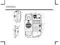
® INSTALLATION AND USER GUIDE EUROMW5 or MW10 DELUXE SINGLE LINE TELEPHONE Copyright TeleMatrix Inc. 2000 SAFETY AND COMPLIANCE DOC - NOTICE AND LOAD NUMBER STATEMENT NOTICE: The Canadian Department of Communications label identifies certified equipment. This certification means that the equipment meets certain telecommunications network protective, operational and safety requirements. The Department does not guarantee the equipment will operate to the user's satisfaction. Before installing this equipment, users should ensure that it is permissible to be connected to the facilities of the local telecommunications company. The equipment must also be installed using an acceptable method of connection. In some cases, the company's inside wiring associated with a single line individual service may be extended by means of a certified connector assembly (telephone extension cord). The customer should be aware that compliance with the above conditions may not prevent degradation of service in some situations. Repairs to certified equipment should be made by an authorized Canadian maintenance facility designated by the supplier. Any repairs or alterations made by the user to this equipment, or equipment malfunctions, may give the telecommunications company cause to request the user to disconnect the equipment. Users should ensure for their own protection that the electrical ground connections of the power utility, telephone lines and internal metallic water pipe system, if present, are connected together. This precaution may be particularly important in rural areas. Caution: Users should not attempt to make such connections themselves, but should contact the appropriate electric inspection authority, or electrician, as appropriate. The Load Number (LN) assigned to each terminal device denotes the percentage of the total load to be connected to a telephone loop, which is used by the device, to prevent overloading. The termination on a loop may consist of any combination of devices subject only to the requirement that the total of the Load Numbers of all the devices does not exceed 100. An alphabetic suffix is also specified in the Load Number for the appropriate ringing type (A or B), if applicable. For example, LN = 20 A designates a Load Number of 20 and an "A" type ringer. 2 SAFETY AND COMPLIANCE FCC Part 15 Compliance Warning Changes or modifications to this unit not expressly approved by the party responsible for compliance could void the user's authority to operate the equipment. NOTE: This equipment has been tested and found to comply with the limits for Class B digital device, pursuant to Part 15 of the FCC Rules. These limits are designed to provide reasonable protection against harmful interference in a residential installation. This equipment generates, uses, and @an radiate radio frequency energy and, if not installed and used in accordance with the instructions, may cause harmful interference to radio communications. However, there is no guarantee that interference will not occur in a particular installation. If this equipment does cause harmful interference to radio or television reception, which can be determined by turning the equipment off and on, the user is encouraged to try to correct the interference by one or more of the following measures: Reorient or relocate the receiving antenna. Increase the separation between the equipment and receiver. Connect the equipment into an outlet on a circuit different from that to which the receiver is connected. Consult the dealer or an experienced radio TV technician for help. Canadian Emissions Compliance " This digital apparatus does not exceed the Class B limits for radio noise emissions from digital apparatus set out in the Radio Interference Regulations of the Canadian Department of Communications. " "Le present appareil numerique n'emet pas de bruits radiolectriques depassant les limites applicables auix appareils numeriques de la class B prescrites dans le Reglement sur le brouillage radioelectrique edicte par le ministere des Communications du Canada." Europe Compliance The euromwb telephone has been approved to the following standards: iCTR 37 AND TBR 38, EN 60950: 2000, EN 55022: 1998 CLASS B EN 61000-4-2 1995 AS REQUIRED BY EN 55024: 1998 EN 61000-4-3 1996 AS REQUIRED BY EN 55024: 1998 EN 61000-4-4 1995 AS REQUIRED BY EN 55024: 1998 EN 61000-4-5 1995 AS REQUIRED BY EN 55024: 1998 EN 61000-4-6 1996 AS REQUIRED BY EN 55024: 1998 EN 61000-4-8 1995 AS REQUIRED BY EN 55024: 1998 3 IMPORTANT SAFETY INSTRUCTIONS When using your telephone equipment, basic safety precautions should always be followed to reduce the risk of fire, electric shock and injury to persons, including the following: 1. Read and understand all instructions. 2. Follow all warnings and instructions marked on the product. 3. Unplug this product from the wall outlet before cleaning. Do not use liquid cleaners or aerosol cleaners. Use a damp cloth for cleaning. 4. Do not use this product near water, for example, near a bath tub, wash bowl, kitchen sink, or laundry tub, in a wet basement, or near a swimming pool. 5. Do not place this product on an unstable cart, stand, or table. The product may fall, causing serious damage to the product. 6. Slots and openings in the cabinet and the back or bottom are provided for ventilation, to protect it from overheating, these openings must not be blocked or covered. The openings should never be blocked by placing the product on the bed, sofa, rug, or other similar surface. This product should never be placed near or over a radiator or heat register. This product should not be placed in a built-in installation unless proper ventilation is provided. IF UNIT IS EQUIPPED WITH POWER ADAPTER: 7. This product should be operated only from the type of power source indicated on the marking label. If you are not sure of the type of power supply to your home, consult your dealer or local power company. IF ADAPTER IS PROVIDED WITH A GROUNDED TYPE ATTACHMENT PLUG: 8. This product is equipped with a three wire grounding type plug, a plug having a third (grounding) pin. This plug will only fit into a grounding type power outlet. This is a safety feature. If you are unable to insert the plug into the outlet, contact your electrician to replace your obsolete outlet. Do not defeat the safety purpose of the grounding type plug. IF ADAPTER IS PROVIDED WITH A POLARIZED ATTACHMENT PLUG: This product is equipped with a polarized line plug (a plug having one blade wider than the other). This plug will fit into the power outlet only one way. This is a safety feature. If you are unable to inset the plug fully into the outlet, try reversing the plug. If the plug should still not fit, contact your electrician to replace your obsolete outlet. Do not defeat the safety purpose of the polarized plug. 9. Do not allow anything to rest on the power cord. Do not locate this product where the cord will be abused by persons walking on it. 10. Do not overload wall outlets and extension cords as this can result in the risk of fire or electric shock. 11. Never push objects of any kind into this product through cabinet slots as they may touch dangerous voltage points or short out parts that could result in a risk of fire or electric shock. Never spill liquid of any kind on the product. 12. To reduce the risk of electric shock, do not disassemble this product, but take it to a qualified serviceman when some service or repair work is required. Opening or removing covers may expose you to dangerous voltages or other risks. Incorrect re-assembly can cause electric shock when the appliance is subsequently used. 13. Unplug this product from the wall outlet and refer servicing to qualified service personnel under the following conditions: A. When the power supply cord or plug is damaged or frayed. B. If liquid has been spilled into the product. C. If the product has been exposed to rain or water. D. If the product does not operate normally by following the operating instructions. Adjust only those controls, that are covered by the operating instructions because improper adjustment of other controls may result in damage and will often require extensive work by a qualified technician to restore the product to normal operation. E. If the product has been dropped or the cabinet has been damaged. F. If the product exhibits a distinct change in performance. 14. Avoid using a telephone (other than a cordless type) during an electrical storm. There may be a remote risk of electrical shock from lightning. 15. Do not use the telephone to report a gas leak in the vicinity of the leak. SAVE THESE INSTRUCTIONS 4 IMPORTANT SAFETY INSTRUCTIONS 1. 2. 3. 4. Never install the telephone wiring during a lightning storm. Never install the telephone jacks in wet locations unless the jack is specifically designed for wet locations. Never touch un-insulated telephone wires or terminals unless the telephone line has been disconnected at the network interface. Use caution when installing or modifying telephone lines. NOTIFICATION TO TELEPHONE COMPANY NOTIFICATION TO THE TELEPHONE COMPANY Before you may connect your telephone you must notify the telephone company of particular line(s)to which such connections is to be made, and provided to the telephone company the FCC registration number and ringer equivalence number of the registered protective circuitry. The customer shall give notice to the telephone company upon final disconnection of such equipment or circuitry from the particular line(s). MALFUNCTION OF TELEPHONE In the event that your telephone fails to work properly during your ownership and use of it, you should disconnect it from the telephone line to determine if it is your phone which is not working properly or if it is problem in the telephone company's network. If the problem is with your telephone you should discontinue its use until it is repaired. TELEPHONE CONNECTION REQUIREMENTS Except for telephone company provided ringers, all connections to the telephone network shall be made through standard telephone company provided jacks, in such a manner as to allow for easy and immediate disconnection of the terminal equipment. Standard jacks shall be so arranged that if the plug connected thereto is withdrawn, no interference to the operation of the equipment at the customer's premises which remains connected to the telephone net work shall occur by reason of such withdrawal. These telephones may not be used on party lines or coin operated lines. CHANGES IN TELEPHONE COMPANY EQUIPMENT OR FACILITIES The telephone company is entitled to make changes in its facilities equipment, operations, and procedures. Should these changes be expected to render your terminal equipment incompatible with the telephone company's facilities you will be given sufficient notice to allow you to make the necessary modification to your terminal equipment without any interruption of your service. SAVE THESE INSTRUCTIONS 5 CONTENTS Features ...........................................………..……………………………………................................... 7 Controls ...........................................................................……………………………………………….. 8 Definitions of Controls ………………………………………………………………………………………. 9 Installation .....................................................................……………………………………………........ 10 Wall Mounting .....................................….......................……………………………………………........ 11 Message Waiting Feature ………………………………………………………………………………….... 12 Message Waiting Programming ……………………………………………………………………………. 13 TouchLiteTM Feature Programming …………………………………………………………………….… 14 Operation ........................................................................…………………………………………….….. 15 Care and Maintenance ..................................................……………………………………………....... 21 Service …………………………………………………..……………………………………….………… 22 Warranty .......................................................................……………………………………………....... 23 6 FEATURES • • • • • • • • • • • • • • • • • One Line Convenient Data Port No Battery Maintenance TouchLiteTM One Touch Message Retrieval Feature Switch Selectable Message Waiting Tone Dialing 5 or 10 Secure Programming Speed Dial Memory Locations Programmable Flash Function (100mS, 600mS) Pause Function (3.6mS) Digital Handset Volume Control Redial Key Function (31 digits) (optional) Smart Port Programming (when available) 2-way Speakerphone Feature HI/LOW Ringer Volume Control Switch Desk or Wall Mountable Hearing Aid Compatible Fully Modular, Easy To Install 7 CONTROLS 15 2 12 14 HANDSET 4 13 NEON LR1 LR2 STORE LED SIE TYPE 1 10 11 9 FOR MESSAGES 1 2 3 PRESS HERE 5 6 DATA 4 REDIAL 7 R ECALL 3 8 8 9 HI 7 LIN E 1 VOL LOW * 0 # 5 6 FIGURE 1 8 DEFINITION OF CONTROLS 1. Handset Clip ………………………………….. Retains the handset when the phone is wall mounted. 2. Handset ..........…………..………….........…... Hearing aid compatible, low profile styling. 3. Ringer Control ………….……….……………. Adjusts the volume of the ringer to HI/LOW setting. 4. Handset Jack ……………………………….… Modular receptacle where handset cord plugs into the base unit. 5. Handset Volume Control Increases or decreases the loudness of the receiving speech volume when pressed. 6. Dial Pad ………………………………….……. Large keys used for dialing. 7. Redial/Pause Key …………………………….. Used to redial the last number or to program a pause into memory.* 8. Recall/(Flash) Key ……………...…………… used to provide a time line break to access PBX/Centrex line features.* TM 9. TouchLite 10. Speed Dial Access Keys ………….…………. 10 programmable speed dial memory keys. 11. Data Port ………………………………………. Used to connect a computer modem, fax machine, or answering device. 12. Message Waiting Selector Switch 1 ………… Used to select different Message Waiting Systems. 13. Message Waiting Selector Switch 2 ………… Used to select different Message Waiting Systems. 14. Store Key ………………………………………. Submerged key used to program numbers into Speed Dial memory.* 15. Smart Port ……………………………………… Used for automated programming (when available) or connection port for an Siemens Message Waiting ………………. Dual function Visual Message Waiting Indicator and Speed Dial for message retrieval. Message Waiting System (optional card insert) .** * Note that these keys may be submerged. ** Contact your Distributor to purchase the optional circuit board insert. 9 INSTALLATION CONTENTS: Packaged with Each EUROMW5 or MW10 Telephone: (Figure 2): FOR MESSAGES ● Base Unit ● Handset ● 15’ Line Cord ● Coiled Handset Cord ● Clear Plastic Overlay ● Paper Index Card ● Instructions ● Optional Wall Mounted Plate 1 2 3 4 5 6 7 8 9 PRESSHERE REDI AL RECALL VOL * 0 # FIGURE 2 TO PREPARE THE EUROMW10 TELEPHONE FOR USE: 1. Plug one end to the modular handset cord into the modular receptacle on the left side of the unit. Plug the other end of the cord into the handset receptacle (figure 3). 2. Plug one end of the straight modular telephone line cord into the line jack at the front of the base unit. 3. Plug the other end of the straight line cord directly into an appropriate telephone jack (figure 4). 4. Lift the telephone handset and listen for dial tone to ensure proper connection to the telephone line. LIN E FIGURE 3 FIGURE 4 10 WALL MOUNTING 1. 1. 2. 3. HANDSET RETAINING HOOK UNSNAP ROTATE 180 . SNAP INTO PLACE. A removable clip to hold the handset secure when in the wall mounted position is located below the hook switch. FIGURE 5 Remove the clip hook, turn it 180 degrees round and slot it back into place (figure 5). 2. INSTALLATION FOR WALL MOUNTING M OUNTING WEDGE Plug one end of the line cord into the line jack on the top of the base unit. LABEL-IC LABEL-S/NO. LABEL-FCC 1.PRES S THE RELEAS E TABS . 2.SNAP INTO PLACE. Plug the other end of the line cord into the wall jack receptacle. LABEL-ETL Guide the phone onto the studs on the wall jack. 2 4V 48V OFF L1 L2 Pull down firmly until you feel it snap into place. FIGURE 6 The unit is now wall mounted (figure 6). 11 MESSAGE WAITING FEATURE The EURO telephone is equipped to support a number of standard Message Waiting Systems: Neon, line reversal, LED and Siemens (optional Siemens MW board is available from Telematrix Equipment LLC). The Message Waiting System (MW) is pre-set at the factory as indicated by the original order. The programming is done prior to delivery and should only be changed by authorized personnel. When a Message Waiting (MW) signal is received from the PBX or your local telephone provider, the signal lights the red indicator located on the telephone. Message Waiting Switches The EURO Series telephone supports many types of signals. Simply slide the switch to the desired position that is compatible with your PBX or Telephone Company messaging system. Note: these switches are factory pre-set to the original order request. The are two switches located at the top of the base underneath the paper overlay. The wording is described below: LED (low voltage LED light, usually used with the telephone company) NEON (high voltage lamp, usually used with a PBX system) SIE stands for Siemens (optional board required) LR1 and LR2 stand for line reversal normal polarity and reversed polarity. These switches must be in the proper position for the Message Waiting Signal to operate. Be sure to know what signal type is being sent to the telephone. *Class Visual Message Waiting are features that require subscription to your local telephone company provided services. These telephone features will not work unless you are a subscriber. 12 MESSAGE WAITING PROGRAMMING The message waiting selector switches is located underneath the faceplate. To access remove the clear plastic overlay using a pointed object such as a paperclip and lift off the clear plastic overlay. Re-insert the overlay by aligning one side of the tabs on the overlay into the slots next bend the overlay in the middle and insert the remaining tabs on the other side. Message Waiting This telephone is standard equipped to support a number of message waiting systems. A selector switch is provided underneath the faceplate to select up to two available message waiting systems. 13 TouchLiteTM FEATURE PROGRAMMING Feature Description TouchLitetm is a new innovation that integrates the visual message waiting lamp and a speed dial button, all in one. It allows easy access for guests to retrieve messages. When the message-waiting lamp lights to notify the guest that a message is waiting. A simple press of the red TouchLitetm key connects the guest to the message center or front desk. TouchLitetm also adds an additional memory location to this telephone. Programming TouchLite tm 1. 2. 3. 4. Lift the handset. Press the STORE button to enter the programming mode. Press the red TouchLite tm button where the number is to be stored. Enter the number to be stored using the numeric dial pad. Using the FLASH or PAUSE key to insert a flash or pause in the number string. A flash or pause is considered as a digit in the digit string. 5. Press the STORE button to store the number at the selected location and to exit programming mode. A short beep should be heard to indicate a valid entry. 6. Hang up the handset. Note: if a double beep is heard at any time during the programming, an invalid entry has been entered and the whole process must be started all over again. 14 OPERATION PLACING A CALL USING THE HANDSET Lift the handset; the phone will select the line. Listen for dial tone and adjust the volume control if necessary. Dial out by using the numeric dial pad or by pressing the redial/pause button or by pressing a speed dial button. To end the call, place the handset on hook. RECEIVING A CALL When the phone rings, pick up the handset. Adjust the volume control if necessary. 15 OPERATION Programming a Flash Timing Delay into Speed Dial Memory Flash Timing can be programmed into the Euro Series Telephones speed dial memory. This function allows the user to include a timed line break in the sequence of the dialing patterns when using the speed dial keys. This function may be required for accessing line features provided by your telephone system or local telephone company. NOTE: Each “Flash” function counts as 1 digit when stored into a speed dial memory location OPERATION FLASH OPTIONS (STANDARD PROGRAMMING) The EURO Series is pre-programmed with two standard flash options: 1. Option 1 is the programmable 100ms flash timing 2. Option 2 is the standard default of 600ms flash timing. To change the flash to option 2, the 600ms flash timing: 1. 2. 3. 4. 5. 6. Lift the handset. Press the 'store' button to enter the programming mode. Press digit 2 using the numeric dial pad. Press digit 1 using the numeric dial pad. Press the STORE button to store the new setting and to exit programming mode. A short beep should be heard to indicate a valid entry . Hang up the handset. Note: if a double beep is heard at any time during the programming, an invalid entry has been entered and the whole process must be started all over again. To change the flash back to option 1, the 100ms flash timing: 1. 2. 3. 4. 5. 6. Lift the handset. Press the 'store' button to enter the programming mode. Press digit 2 using the numeric dial pad. Press digit 0 using the numeric dial pad. Press the 'store' button to store the new setting and to exit programming mode. A short beep should be heard to indicate a valid entry . Hang up the handset. Note: if a double beep is heard at any time during the programming, an invalid entry has been entered and the whole process must be started all over again. 17 OPERATION Programming A Pause into Memory Pause(s) can be programmed into the number pattern when speed dial programming memory. This function allows the user to delay the dialing pattern of a number. This function may be required for accessing line features provided by your telephone system or local telephone company. For example, a speed dial number may need to pause during its dialing sequence to insure proper connections. Multiple pauses can be programmed into speed dial for added pause time. NOTE: Each “Pause” function counts as 1 digit when stored into a speed dial memory location.. 18 OPERATION Handset Volume Control The EURO Series telephone is equipped with an ADA/FCC compliant handset volume control located on the face of the phone. When the “Volume” key is pressed, the volume of the handset receiver is increased by 12-15 decibels. The “Volume” key is a slide switch volume control. When pressed in the upward arrow position, the volume will increase. When pressed in the downward arrow position, the volume will decrease. Note: When the handset volume feature is activated, the volume will automatically reset back to its normal default level with hanging up. Ringer Volume Control The Ringer Volume Control Switch is located on the right side of the telephone base. The switch has a setting option for Hi/Low. Note: The Ringer Volume Switch is factory set in the “Hi” position. 19 OPERATION USING THE DATA PORT The EURO Series is equipped with a convenient port on the right side of the base unit. This modular receptacle is used to plug in any standard telephone device such as a computer modem, answering machine or fax machine. 20 CARE AND MAINTENANCE Keep the telephone dry. If it gets wet, wipe it dry immediately. Liquids might contain minerals that can corrode the electronic circuits. Use and store the telephone only in normal temperature environments. Temperature extremes can shorten the life of electronic devices, damage batteries, and distort or melt plastic parts. Keep the telephone away from excessive dust and dirt that can cause premature wear of parts. Wipe the telephone with a damp cloth occasionally to keep it looking new. Do not use harsh chemicals, cleaning solvents, or strong detergents to clean the system. 21 SERVICE INFORMATION When problems arise during installation or service that cannot be resolved using this or related documents, contact the TeleMatrix Technical Service department 8:30a.m. - 4:30p.m. MST: Toll Free: 1-800-462-9446 Direct: 719-638-8821 Fax: 719-638-8815 www.telematrixusa.com Many times a problem is either installation or user related. Please contact TeleMatrix PRIOR to sending a telephone to our service center for repair. In the unlikely event that a factory repair be necessary: 1. Include a brief description of the trouble that you are experiencing. 2. Include a proof of purchase for a repair under warranty. 3. Send the telephone prepaid by UPS or Parcel Post insured to: TeleMatrix, LLC. Customer Care Center 5025 Galley Road Colorado Springs, CO. 80915 TeleMatrix will pay to return the repaired telephone to you. Allow 2-3 weeks for delivery. 22 STATEMENT OF LIMITED WARRANTY STATEMENT OF LIMITED WARRANTY TeleMatrix, Inc. and TeleMatrix Equipment, LLC (TMX) warrants to its [original end customer] [purchaser] that Spectrum, Spectrum Plus and Marquis branded products manufactured by TMX are free from defects in materials and workmanship for five (5) years after the date of purchase, and Regency branded products manufactured by TMX are free from defects in materials and workmanship for three (3) years, other than the following products for which the warranty period shall be one (1) year: handset batteries, either NiCd or NiMH, used in TMX cordless products. If a product fails this warranty during the warranty period, TMX will, at its option, either repair or replace the defective product or parts, or deliver replacements for defective products or parts on an exchange basis at no additional charge to the customer except as set forth below. Repair parts or replacement products may be either new or reconditioned. Products or parts returned to TMX under this warranty will become the property of TMX. Warranties on products repaired by TMX expire at the termination of the original warranty period. This limited warranty does not cover: 1. 2. 3. 4. 5. 6. 7. 8. Products or parts which are damaged, abused or misused; Any damage resulting from improper installation, maintenance or operation of the product; Damage resulting from unauthorized modification or repair of the product, or from improper connection of the product to other equipment; Cords, connectors and replaceable batteries; Damage in transit to the TMX repair facility; Any product or part unless proof of date of purchase is submitted with the product when returned for warranty repair; or Costs incurred by the customer in removing and shipping the product to TMX for repair or replacement, and costs of reinstallation of the product. Products or parts which are not owned and used by the original end user customer. The cost and risk of loss or damage for sending the product to TMX will be borne by the customer. TMX EXPRESSLY DISCLAIMS ALL WARRANTIES EXCEPT THE LIMITED WARRANTY SET FORTH HEREIN, WHICH IS THE SOLE AND EXCLUSIVE WARRANTY OF THE PRODUCT, AND IS IN LIEU OF ALL OTHER WARRANTIES, WHETHER ORAL OR WRITTEN, EXPRESS OR IMPLIED, OR STATUTORY. THERE ARE NO IMPLIED WARRANTIES OF MERCHANTABILITY OR FITNESS FOR A PARTICULAR PURPOSE. THE CUSTOMER’S SOLE REMEDY UNDER THE TMX WARRANTY SHALL BE REPAIR OR REPLACEMENT AS PROVIDED ABOVE. IN NO EVENT WILL TMX BE LIABLE TO CUSTOMER OR ANY OTHER PARTY FOR ANY INDIRECT, INCIDENTAL OR CONSEQUENTIAL DAMAGES, INCLUDING, WITHOUT LIMITATION, DAMAGES OF LOST PROFITS, LOST REVENUES, LOSS OF USE OF FACILITIES OR EQUIPMENT, OR COST OF SUBSTITUTE EQUIPMENT ARISING OUT OF THE USE OR INABILITY TO USE THIS PRODUCT, EVEN IF THE CUSTOMER HAS ADVISED TMX OF THE POSSIBILITY OF SUCH DAMAGES. TMX LIABILITY FOR DAMAGES SHALL NOT EXCEED THE PURCHASE PRICE OF THE DEFECTIVE PRODUCT. This limited warranty is non-transferable without the prior written approval of TMX. It gives the customer specific legal rights. The customer may have other rights which vary under local law. Some jurisdictions may not allow limitations on the term of an implied warranty or exclusions or limitations of incidental or consequential damages. 23