1
TransTalk™ 9000
Digital Wireless System
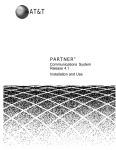
MDW 9030P Wireless Pocketphone
Installation and Use
503-801-160
Comcode 107972010
Issue 2
March 1997
Copyright ©1997 Lucent Technologies
All Rights Reserved
Printed in U.S.A.
Lucent Technologies 503-801-160
Comcode 107972010
Issue 2
March 1997
Notice
Every effort was made to ensure that the information in this book was complete and
accurate at the time of printing. However, information is subject to change. The pictures in
this book are for illustrative purposes only; your actual hardware may look slightly different.
Federal Communications Commission (FCC) and Industry Canada (IC) Information
For details, see Appendix B.
Security
Toll fraud, the unauthorized use of your telecommunications system by an unauthorized
party (for example, persons other than your company’s employees, agents, subcontractors, or persons working on your company’s behalf) can result in substantial additional
charges for your telecommunications services. You are responsible for the security of your
system. There may be a risk of toll fraud associated with your telecommunications system.
You are responsible for programming and configuring your equipment to prevent unauthorized use. Your system administrator should read all documents provided with this product
to fully understand the features that can introduce the risk of toll fraud and the steps that
can be taken to reduce that risk. Lucent Technologies does not warrant that this product is
immune from or will prevent unauthorized use of common-carrier telecommunication
services or facilities accessed through or connected to it. Lucent Technologies will not be
responsible for any charges that result from such unauthorized use.
Trademarks
TransTalk is a trademark of Lucent Technologies and DEFINITY, MERLIN, MERLIN LEGEND, PARTNER, and SYSTIMAX are registered trademarks of Lucent Technologies. Supra
is a registered trademark of Plantronics, Inc.
Warranty
Lucent Technologies provides a limited warranty for this product; see Appendix A.
Ordering Information
The order number for this book is 503-801-160. The order number for the MDW 9030P
Wireless Pocketphone Quick Reference is 503-801-161. To order additional copies of
these reference materials, call 1 800 457-1235 or 1 317 361-5353. To order parts and
accessories, see “Ordering Replacement & Optional Parts” in Chapter 4.
Customer Support
In the continental U.S., call 1 800 628-2888 if you need assistance when using your
wireless phone with a PARTNER, MERLIN, or MERLIN LEGEND system. Consultation
charges may apply. For all other systems, follow the procedure you normally use to get
support for your communications system.
Outside the continental U.S., contact your Lucent Technologies Representative or local
Authorized Dealer.
Contents
1
Introduction
1-1
About TransTalk™ 9000 Products
1-1
What Is a Wireless Phone?
1-1
TransTalk 9000 System
1-1
About the MDW 9030P Pocketphone
Privacy Information
2
1-3
1-3
Where Can You Use Your Pocketphone?
1-3
Parts List
1-4
Additional Parts
1-5
Spare Battery and Headset
1-6
Installing the MDW 9030P Pocketphone
2-1
Important Safety Instructions
2-1
Guidelines for Safe and Efficient Operation
2-2
Basic Safety Precautions for Installation and Use
2-3
Additional Safety Instructions
for Installation Personnel
2-4
AC Outlet Check
2-5
Radio Modules and Carriers
2-6
Key Components
2-7
Positioning a Radio Module or Carrier(s)
2-9
Wireless Test Mode
2-11
Installing a Single Radio Module
2-13
Setting the Power Level
2-15
Setting the Control/Expansion DIP Switch
2-17
Installing a Single Carrier on a Shelf or Desk
2-18
Installing a Single Carrier on a Wall
2-21
Installing Multiple Carriers
2-24
Installation Self-Test
2-29
Handset
2-30
Inserting and Removing the
Handset’s Battery Pack
2-30
Changing the Communications System Setting
2-31
Filling Out the Handset Label
2-32
i
Battery Charger
3
Positioning the Battery Charger
2-33
Installing the Battery Charger
2-33
Inserting a Battery Pack into
the Spare Battery Compartment
2-35
Removing a Battery Pack
from the Spare Battery Compartment
2-35
Inserting the Handset into the
Battery Charger's Handset Cradle
2-36
Removing the Handset
from the Handset Cradle
2-36
Using the MDW 9030P Pocketphone
3-1
Important Safety Instructions
3-1
The Handset
3-1
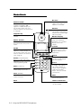
Handset Controls
3-2
Column and Select Buttons
3-3
Handset Display
3-4
Volume Control
3-7
Carrying Your Pocketphone
3-7
Antenna
3-8
Changing the Handset Settings
3-8
Test Modes
3-12
"Waking Up" the Phone
3-15
Making a Call
3-15
Answering a Call
3-15
Manually Selecting a Line or Programmed Button
3-16
Preselecting a Line
3-16
Using a Headset
3-17
The Battery Charger
ii
2-33
3-19
Battery Charger Features
3-19
Extending Battery Life
3-21
4
5
6
Maintaining the MDW 9030P Pocketphone 4-1
Important Safety Instructions
4-1
Removing a Radio Module
from the Carrier
4-1
Swapping Extensions
4-3
Replacing the Antenna
4-4
Ordering Replacement & Optional Parts
4-5
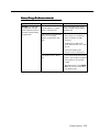
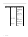
Troubleshooting
5-1
Procedures
5-1
Installation Problems
5-1
Handset Problems
5-4
Battery Problems
5-6
Voice Quality Problems
5-7
Range Problems
5-10
Battery Charger Problems
5-13
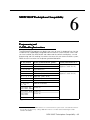
MDW 9030P Pocketphone Compatibility
6-1
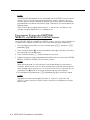
Programming and
Call Handling Instructions
6-1
Programming Features for PARTNER,
MERLIN, and MERLIN LEGEND Systems
6-2
Communications System Compatibility
6-3
PARTNER Systems
6-3
MERLIN Systems
6-5
System 25, System 75, System 85, and
DEFINITY Systems
6-9
Warranty and Repair Information
Lucent Technologies Limited Warranty
and Limitation of Liability
Limitation of Liability
Repair Information
A-1
A-1
A-2
A-2
In-Warranty Repairs
A-2
Post-Warranty Repairs
A-3
iii
B
Regulatory Information
B-1
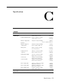
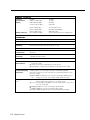
C
Specifications
C-1
IN
Index
IN-1
Battery Charger Wall-Mounting Template
iv
Last Page
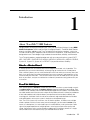
Introduction
1
About TransTalk™ 9000 Products
Congratulations on the purchase of your new TransTalk 9000 Digital Wireless System MDW
9030P Pocketphone. MDW stands for "Multi-Line Digital Wireless." The MDW 9030P Pocketphone is the latest addition to the TransTalk 9000 family of wireless products, which also
includes the MDW 9000 Telephone and the MDW 9010 Telephone. All of these phones are
designed to Lucent Technologies' high standards for convenience, reliability, and innovation.
TransTalk 9000 products are designed to work with your communications system (PARTNER , PARTNER II, PARTNER Plus, MERLIN , MERLIN II, MERLIN Plus, MERLIN LEGEND ,
System 25, System 75, System 85, or DEFINITY ) to provide wireless flexibility.
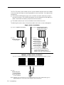
What Is a Wireless Phone?
A wireless phone has no handset cord and no telephone line cord, so it is portable. This
portability lets you move around freely, without giving up the features of a wired phone.
With a wireless phone, you can make and receive calls even when you are away from your
desk, thus remaining accessible and responsive to your customers and coworkers as you
move around your work area. Time-sensitive work issues will not need to wait until you are
back at your desk, and you can reduce the number of (sometimes costly) phone calls you
must return.
TransTalk 9000 System
Your wireless phone's handset is linked with your communications system through a matching radio module, not through the battery charger where the handset sits for charging. Each
handset can be used only with the radio module packaged with the handset. The handset and
the radio module each have the same unique security code and serial number (on the bottom
of the radio module and inside the battery compartment of the handset) to identify the
matching pair. And there is built-in and secure automatic registration between the handset
and radio module, so that your system is ready to use after powering up.
Your TransTalk system may have from 1 to 18 wireless phones. In order to use multiple
wireless phones within the same zone (area of coverage), you also need a carrier (also
known as a backplane). A carrier holds up to six radio modules, and synchronizes radio
signals for proper operation of multiple phones, ensuring consistent voice quality and
range. Up to three carriers can be linked to support up to 18 wireless phones in a single
zone; linked carriers are automatically synchronized with each other.
Introduction 1-1
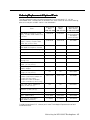
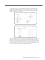
The TransTalk 9000 system enables you to use several different phone and carrier models
in the same zone, but there are some compatibility issues to consider. You need to know
the following:
■
The name of the MDW phone (9000, 9010, or 9030P), located in the battery compartment of the handset. (For an MDW 9000 phone, you also need to know the Apparatus
Code, also located in the battery compartment of the handset.)
■
The model number of your carrier, located on the left side of the carrier.
The following illustration shows which phone models and carriers can be used together:
Single Carrier Installation
If you have a Model 117A1 Carrier...
If you have a Model 117A1A Carrier,
Model 117A2 Carrier, or
Model 117A3 Carrier...
Use only...
You can use...
MDW 9000 phones
(Code 7815H)
MDW 9000 phones
(Code 7815H)
MDW 9000 phones
(Code 7815H03A)
MDW 9010 phones
(Code 7815H04A)
MDW 9030P phones
(Code 7815H05A)
Note: You can use Code 7815H phones
together with other phones only in a
Model 117A1A, Model 117A2, or
Model 117A3 single carrier installation.
Multiple (3 Max) Carrier Installation
If you have multiple Model 117A2 or Model 117A3 System Expansion Carriers (or both)...
Use only...
MDW 9010 phone
(Code 7815H04A)
MDW 9030P phone
(Code 7815H05A)
Note: Multiple carrier installations must use MDW 9010 phones and/or MDW 9030P phones.
MDW 9000 phones cannot be used in multiple carrier installations.
1-2 Introduction
About the MDW 9030P Pocketphone
The MDW 9030P Pocketphone is not only wireless, but it is also lightweight and pocketsized. A removable carrying clip and a lanyard are provided with the handset. You can
use either the clip or the lanyard for hands-free portability. The MDW 9030P also has a
headset connector to accommodate an optional headset.
You can be notified of an incoming call by either an alerter (which rings) or a vibrator, or
both. There is a five-line display that shows information you would see on a wired system
phone's display (with the exception of the time ), icons representing various handset
functions (such as the alerter and the vibrator), and the status of up to 12 telephone lines.
The MDW 9030P provides Redial, Hold, Mute, Transfer, and Conference buttons, and
provides the capability to program additional features on unused line buttons.
Privacy Information
The MDW 9030P Pocketphone is designed to protect the privacy and security of your voice
conversation. The phone uses continuously changing radio frequencies and digital encoding techniques to make it impossible for eavesdropping to occur through the use of commercially available analog radio scanners.
Where Can You Use Your Pocketphone?
The MDW 9030P Pocketphone can be used in most typical office buildings, in warehouses,
malls, and even in outdoor areas such as loading docks. The location of the radio module
greatly affects the performance of the MDW 9030P, so you should use the Wireless Test
Mode described in Chapter 2 to determine the best place to install the radio module. Repeat
the tests several times with the radio module positioned in a different location each time.
To perform the tests, all you need is an electrical outlet for the radio module and a charged
battery pack in the handset.
Introduction 1-3
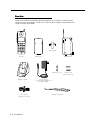
Parts List
Along with this book and the MDW 9030P Pocketphone Quick Reference, the box should
contain the items shown below. If it does not, call for customer support as described on the
inside front cover of this book.
212
MSG
5
555 1212
ON
6
7
8
1
2
3
4
A
B
C
D
POWER
RADIO
PASS
On/Off
Redial
Mute
1
2 ABC
3 DEF
Conf
4 GHI
5 JKL
6 MNO
Trans
7PQRS
8 TUV
9 WXYZ
Feat/P
Carrying Clip
0OPER
Hold
TransTalk
Handset
Radio Module
Battery Pack
Wall Spacers (2)
SPARE
HANDSET
REFRESH
Battery Charger
8-foot (2.4 m)
Telephone Line Cord
1-4 Introduction
11-foot (3.4 m)
Power Cord/AC Adapter for
Battery Charger
18" (0.5 m) Lanyard
Philips Head
Wood Screws (2)
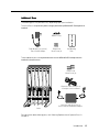
Additional Parts
The following parts may be necessary, depending upon your installation.
This Kit of Parts is required only when a single (stand-alone) MDW 9030P Pocketphone is
installed:
Rubber Feet (4)
Radio Module 11-foot (3.4 m)
Power Cord/AC Adapter
Philips Head
Wood Screws (2)
Wall Mounting
Plate
These additional parts are required when two or more MDW 9030P Pocketphones are
installed in the same zone:
4
T RANSTALK
Philips Head
Wood Screws (4)
2
N
2
O
1
O
1
N
ION
CAUT
ONLY
USECABLE
AT&T 667896
847
P⁄N IN
OUT
OF
OUT
1
2
3
4
5
Expansion Cable 6-foot (1.8 m)
for multiple-carrier installation
SYNC
6
Carrier Assembly 25-foot (7.6 m)
Power Cord and Standard AC Adapter
Carrier
For information about ordering parts, see "Ordering Replacement & Optional Parts" in
Chapter 4.
Introduction 1-5
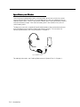
Spare Battery and Headset
One nickel metal hydride battery pack, which provides up to 3 hours of talk time, comes
with your MDW 9030P Pocketphone. For extended phone usage, you should purchase an
additional battery pack. You can store the extra battery pack in the Spare battery compartment of the battery charger. Then when the battery pack in the handset is low, you can
switch battery packs.
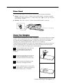
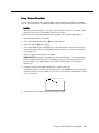
To help you answer calls, an optional Supra® 9030 headset can be attached to the connector on the bottom of the handset to allow hands-free conversation. For instructions for
connecting the headset, see "Using a Headset" in Chapter 3.
Spare Battery
Pack
Supra 9030 Headset
For ordering information, see "Ordering Replacement & Optional Parts" in Chapter 4.
1-6 Introduction
Installing the MDW 9030P Pocketphone
2
Important Safety Instructions
This book contains instructions related to safety labels on the product:
!
The exclamation point within an equilateral triangle is intended to alert the
user to the presence of important operating and maintenance (servicing)
instructions in the literature accompanying the product.
!
WARNING indicates the presence of a hazard that can cause severe or fatal
personal injury if the hazard is not avoided.
!
CAUTION indicates the presence of a hazard that will or can cause minor
personal injury or property damage if not avoided.
This phone is designed to provide trouble-free performance without any special maintenance procedures. To reduce the risk of accidental damage:
■
Keep the phone in an area free of dust, smoke, and moisture; do not block the air
vents by placing objects on top of the radio module.
■
Do not place the phone or battery charger near a heating duct, radiator, or other heat
source, and do not drop or expose it to excessive shock or vibration.
■
Unplug the battery charger, radio module, or carrier if its power cord is damaged, if
liquid is spilled into it, or if its housing becomes cracked or otherwise damaged.
■
To clean your phone, wipe the outside housing with a soft, dust-free cloth. If absolutely
necessary, you may use a cloth slightly dampened with a mild soap and water solution. Dry quickly with a soft cloth.
!
CAUTION:
Your phone contains sensitive electronic parts. Never submerge it in any kind of
liquid, and never use liquid or aerosol cleaners, detergents, alcohols, solvents,
abrasive cleaners, or an excessive amount of water when cleaning the housing and
faceplate. To do so could result in irreparable damage.
Installing the MDW 9030P Pocketphone 2-1
Guidelines for Safe and Efficient Operation
Your wireless telephone is a radio transmitter and receiver. When the phone is turned on,
it receives and sends out radio frequency (RF) energy. The phone operates in the frequency range of 902–928 MHz. Your hand-held wireless telephone uses the digital TDD
mode. The power is transmitted in bursts at a 200 Hz pulsed repetition rate. The peak
envelope transmit power is 325 mW or less.
Exposure to Radio Frequency Energy
The design of your wireless telephone complies with the latest Institute of Electrical and
Electronic Engineers (IEEE) and the American National Standards Institute (ANSI) safety
levels with respect to human exposure to RF energy. Of course, if you would like to limit
RF exposure even further, you may choose to control the duration of your calls.
Cardiac Pacemakers
!
CAUTION:
The MDW 9030P handset is a radio device and, like all radio devices, should not
be placed next to a pacemaker.
Preliminary studies performed at the US Food and Drug Administration (FDA) and elsewhere have shown that when digital cellular telephones are placed very close to implanted cardiac pacemakers, interference with the operation of the implanted pacemaker
can occur. These preliminary studies show that interference does not occur when there is
a reasonable distance between the telephone and the implanted pacemaker and stops
when the phone is turned off or moved so that it is more than 6 inches (15 cm) from the
pacemaker. Digital cellular telephones operate at .6 W. TransTalk wireless telephones
operate at a lower peak power of 325 mW or less (100 mW, on an average).
Until more is known, the FDA suggests that people with pacemakers may want to take
some simple precautions when using or carrying digital wireless telephones to ensure that
there is ample distance between the digital wireless thelephone and the pacemaker—by
not placing the phone next to the pacemaker implant (for example, in a shirt or a coat
pocket directly over the pacemaker implant) when the phone is on and ready to receive a
call and holding it to the ear opposite the side of the body where the pacemaker is
implanted when using the phone. Consult your physician or medical device manufacturer
to determine if additional precautions are necessary.
Hearing Aid Compatibility
Most electronic equipment, such as equipment in hospitals is shielded from RF energy.
However RF energy from wireless telephones may affect some electronic equipment.
Although the TransTalk wireless telephone is compatible with inductively-coupled hearing
aids, you should consult your physician or hearing aid manufacturer to determine if your
hearing aid is adequately shielded from external RF energy. The operation of inadequately shielded medical devices may be adversely affected when a portable wireless
telephone is operating in close proximity.
2-2 Installing the MDW 9030P Pocketphone
Basic Safety Precautions for Installation and Use
Always follow these basic safety precautions when installing or using this product to
reduce risk of injury from fire or electric shock.
!
WARNING:
Installation of this equipment for In-Range Out of Building (IROB) conditions
requires the use of protectors. See the documentation that came with your
communications system for more information.
!
CAUTION:
This equipment is for installation on Lucent Technologies PARTNER, PARTNER Plus,
PARTNER II, MERLIN, MERLIN Plus, MERLIN II, MERLIN LEGEND, System 25, System
75, System 85, and DEFINITY communications systems only.
■
Read and understand all instructions in this book before using this product.
■
Observe all warnings and instructions marked on the product.
■
Do not use the product near water or when you are wet. If the product comes in contact
with any liquids, unplug the power cord and telephone line cords immediately. Do not
plug the product back in until it has dried thoroughly.
■
Never push objects of any kind into this product through housing slots, since the objects
may touch hazardous voltage points or short out parts that could result in a risk of electric
shock. Never spill liquid of any kind on the phone.
■
If you suspect a gas leak, report it immediately, but use a phone away from the area in
question. The phone’s electrical contacts could generate a tiny spark. While unlikely, it is
possible that this spark could ignite a heavy concentration of gas. This product is not
approved for use in areas labeled by the Occupational Safety and Health Administration
(OSHA) as “explosive environments.” Only “Explosive Atmosphere Telephones” may be
used in such hazardous environments.
■
Unplug this product from wall outlets and telephone jacks before cleaning. Clean
exposed parts with a soft, damp cloth. Do not use liquid or aerosol cleaners.
■
Unplug this product from the wall outlet, remove the telephone line cord from the
modular wall jack or communications system switch/control unit, and refer servicing to
qualified service personnel under the following conditions:
–
When the power cord or plug is damaged or frayed.
–
If the product does not operate normally by following the operating instructions.
Adjust only those controls that are covered by the operating instructions because
improper adjustment of other controls may result in damage and will often require
extensive work by a qualified technician to restore the product to normal operation.
–
If the product has been dropped and the housing has been damaged.
■
This product should be serviced by (or taken to) a qualified service center when service
or repair work is required. Do not open the product, there are no user-serviceable
components inside.
■
Always unplug the power cord/AC adapter for the carrier or carriers from the wall
outlet when:
–
Removing a radio module
–
Moving a radio module to a new slot in the carrier
Installing the MDW 9030P Pocketphone 2-3
– Installing a new radio module
■
–
Connecting or disconnecting telephone line cords
–
Adding a carrier
Use only the type of battery pack shipped with this product.
!
WARNING:
The rechargeable battery pack may contain elements that are harmful to the
environment (for example, nickel). Do not burn or puncture the battery pack. Like
other batteries of this type, if it is burned or punctured, it could release toxic
material which could cause injury. Do not dispose of it in household garbage.
For information about recycling or proper disposal, consult your local solid waste
(garbage) collection or disposal organization.
Additional Safety Instructions
for Installation Personnel
■
Install the product to meet all environmental and electrical requirements listed in
Appendix C.
■
All wiring that connects to this equipment and becomes part of the building wiring
must be a minimum of CLASS 2 or UL (Underwriters Laboratories) Listed Communications cable.
■
Do not install telephone wiring during a lightning storm.
■
Do not install telephone jacks in a wet location unless the jack is specifically designed
for wet locations. Never touch uninsulated telephone wires or terminals unless the
telephone line has been disconnected at the network interface.
■
Use caution when installing or modifying telephone lines.
■
Install this product securely on a stable surface. Damage may result if the product
falls.
■
Never place this product near or over a radiator or heat register.
■
Slots and openings in the housing and the back or bottom are provided for ventilation.
To protect the housing from overheating, these openings must not be blocked or
covered. Therefore, do not place the product on a bed, sofa, rug, or other similar
surface. Also, do not place this product in an enclosed area unless proper ventilation
is provided.
■
Install this product in a protected location where no one can step on or trip over power
cords and telephone line cords. Do not place objects on the cords that may cause
damage or abrasion.
■
Do not allow anything to rest on the power cord. Do not locate this product where the
cord will be abused by persons walking on it. Do not overload wall outlets as this can
result in the risk of fire or electric shock. Do not staple or otherwise attach the power
cord to building surfaces.
■
Use only the power supply (Comcode 847713583) shipped with this product for the
battery charger.
■
Use only the power supply (Comcode 847523404) shipped with this product for the
radio module.
2-4 Installing the MDW 9030P Pocketphone
■
Use only the power supply (Comcode 847224227) shipped with the carrier.
■
Use only the correct power source. If you are not sure of the power supply to your
location, consult your local power company.
■
This product uses a 3-prong plug. Such plugs are designed for your safety. Do not
attempt to defeat this purpose. If your wall outlet will not accept the plug, the outlet
should be replaced by an electrician.
!
WARNING: Risk of Electric Shock
Failure to properly ground this product will result in a risk of electrical shock, which
can cause serious personal injury. This product requires a 3-prong AC outlet for
safe operation. You should have your outlet checked by a qualified electrician (see
"AC Outlet Check" below) before connecting this equipment.
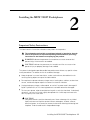
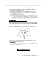
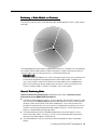
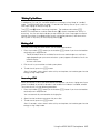
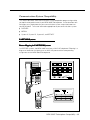
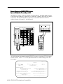
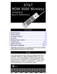
AC Outlet Check
Have a qualified electrician check all of the outlets into which the MDW 9030P radio modules or carriers as well as the communications system switch/control unit will be plugged.
The electrician should check that the hot, neutral, and ground wires are properly connected
to the outlet by using a circuit tester.
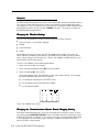
The outlet can also be tested using a voltmeter by taking the measurements as shown:
120 Volts
Neutral
Less than
1 volt
Phase
G
120
volts
If the outlet does not meet the electrical specifications for grounded outlets, your MDW
9030P Pocketphone may not operate properly.
IMPORTANT:
If there is no current to the outlet or the voltages are not correct, the problem should be
corrected by a qualified electrician.
Go to “Radio Modules and Carriers.”
Installing the MDW 9030P Pocketphone 2-5
Radio Modules and Carriers
This section explains how to install radio modules and carriers. You should proceed through
this section in the following order:
1. “Key Components”
2. “Positioning a Single Radio Module or Carrier(s)”
3. "Wireless Test Mode"
4. Choose one of the following paths, depending upon which components you are installing:
■
If you are installing a single radio module, go to “Installing a Single Radio Module.”
■
If you are installing a single carrier (from two to six radio modules), go to “Setting
the Power Level.” Then go to either:
– “Installing a Single Carrier on a Shelf or Desk” or
– “Installing a Single Carrier on a Wall”
■
If you are installing multiple (up to three) carriers (from 7 to 18 radio modules),
go to all of the following, in order:
a. “Setting the Power Level,” then
b. “Setting the Control/Expansion DIP Switch,” then
c. “Installing Multiple Carriers.”
5. “Installation Self-Test”
NOTE:
The illustrations in this chapter depict PARTNER system hardware; your hardware may
differ from these illustrations.
2-6 Installing the MDW 9030P Pocketphone
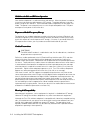
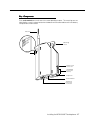
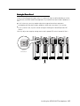
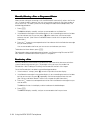
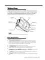
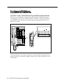
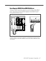
Key Components
Each radio module communicates with a corresponding handset. The matching sets are
identified by a serial number located on the bottom of the radio module and in the battery
compartment of the handset.
Antenna
R
WE
PO
DIO
RA
SS
PA
Mounting
Hook
dio
Ra ule
d
Mo WER
LEDs
PO
DIO
RA
SS
PA
Power Cord
Connector
Card Edge
(Cover not
shown)
Snap Lock
Serial Number
Telephone
Line Cord
Connector
Installing the MDW 9030P Pocketphone 2-7
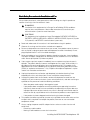
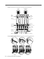
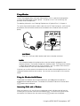
A carrier is required when installing two or more MDW 9030P Pocketphones.
2
1
O N
1
O N
Radio
Module
Mounting
Rods
Control/Expansion
DIP Switch
2
Power DIP
Switch
4
T RANS TALK
Radio
Module
Mounting
Rods
Wall Mount
Hole
Wall Mount
Hole
In Jack
Power Cord
Connector
(hidden)
Out Jack
ION
ONLY
USECABLE
AT&T 667896
847
P⁄N
IN
1
O N
2
1
O N
2
CAUT
Out of Sync LED
OUT
OF
OUT
SYNC
Card Edge
Connectors
Card Edge
Connectors
Slot
Numbers
1
2
3
4
5
Slot
Numbers
6
Wall Mount
Hole
Wall Mount
Hole
Cable
Manager Slot
Rear
Exit Slots
Using the expansion cable provided with each carrier, you can link up to three carriers.
OUT
To
Expansion
Carrier #1
OUT
Carrier #2
4
4
T RANS TALK
O N
2
O N
2
1
2
1
O N
2
3
4
Control
Carrier
5
6
ON
ONLY
USECABLE
AT&T 7896
84766
P⁄N
IN
OUT
1
T RANS TALK
ON
CAUTI
1
2
O N
1
4
T RANS TALK
ON
CAUTI
ONLY
USECABLE
AT&T 7896
84766
P⁄N
IN
OUT
IN
OUT
YNC
OF S
CAUTI
ONLY
USECABLE
AT&T 7896
84766
P⁄N
IN
2
To
Expansion
OUT
YNC
OF S
O N
OUT
YNC
OF S
IN
1
IN
Carrier #1
CAU
Y
ONL
USECABLE
6
AT&T4766789
8
P⁄ N
2
OUT
Y
ONL
USECABLE
6
AT&T4766789
8
P⁄ N
TION
O N
Y
ONL
USECABLE
6
AT&T4766789
8
P⁄ N
From
Expansion
From
Control Carrier
ON
I
CAUT
1
ON
I
CAUT
OUT
OF SYNC
OUT
1
2
3
4
Expansion
Carrier #1
2-8 Installing the MDW 9030P Pocketphone
5
6
OUT
OF SYNC
OUT
1
2
3
4
Expansion
Carrier #2
5
6
OF SYNC
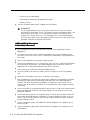
Positioning a Radio Module or Carrier(s)
Each of your handsets and its corresponding radio module operates within a single zone of
coverage:
Approximately
500 to 900 feet in a
typical office building;
up to 1200 feet in
an unobstructed
environment
POWER
RADIO
PASS
Single Radio Module,
Single Carrier, or
Multiple Carriers
The range depends on your particular operating environment. For indoor use, walls between
the handset and the radio module will reduce the phone’s range. Avoid concentrations of
structural metal, such as steel and aluminum, and reinforced concrete.
IMPORTANT:
The MDW 9030P Pocketphone has a built-in testing feature that you can use before final
installation to help determine proper placement of the radio module. To perform the
tests, all you need is an electrical outlet for the radio module and a charged battery
pack in the handset (you do not need a communications system switch/control unit).
The tests are described in “Wireless Test Mode” later in this chapter.
General Positioning Rules
Failure to observe the following rules regarding location and use will result in poor
performance of your MDW 9030P Pocketphone.
■
■
■
Position the radio module or carrier(s) in a central location, relative to the handset(s) usage
area, leaving at least 6 feet (1.8 m) between the radio module or carrier(s) and the communications system switch/control unit or other wired phones. If your switch/control unit is
located in a remote location, you may have to run a telephone line cord from your switch/
control unit to the centrally positioned radio module or carrier(s). The line cord maximum
length is 1,000 feet (333 m) of 26-gauge cable.
The radio module or carrier(s) should be placed high on the wall for optimum voice
quality and range. Allow 6–12 inches (15.2–30.5 cm) of space between the top of the
antenna on the radio modules and the ceiling.
The radio module or carrier(s) should never be installed above a drop, suspended
ceiling.
Installing the MDW 9030P Pocketphone 2-9
■
■
■
■
The radio module or carrier(s) should not be within 3 feet (.9 m) of any large metal
object, and should not have metal objects in the line of sight to the operating area of the
handset.
The radio module or carrier(s) should not be within 6 feet (1.8 m) of equipment with
microprocessors such as answering machines, personal computers, and fax
machines; control units, communications system switches, or other phones
(especially speakerphones); competing radio devices such as wireless bar-code
scanners; electromagnetic equipment such as electric motors; or electrical main
power feeds, junction boxes, circuit-breaker panels, fuse boxes, or 220-volt power
lines.
The radio module or carrier(s) should not share the same power line as equipment with
microprocessors such as answering machines, personal computers, and fax machines; or
electromagnetic equipment such as electric motors.
If your communications system uses an uninterruptible power supply, such as a backup
generator, you may want to connect the radio module or carrier(s) to that power supply.
Additional Rules for Installing a Single Radio Module Only
■
■
■
Installing a single radio module on a shelf or desk is not recommended, because it
greatly reduces the range and quality of the transmission.
Install a single radio module within 3 feet (0.9 m) of either side of, and within 6 to 8 feet
(1.8 to 2.4 m) above, a properly grounded 3-prong electrical outlet that is not controlled
by an on/off switch.
You can install a single radio module in a remote location using a telephone line cord to
connect the radio module to the communications system switch/control unit. IROBs
must be used for out-of-building installations.
! CAUTION:
A radio module cannot be installed outdoors.
Additional Rules for Installing One or More Carriers
■
■
■
Install carrier(s) within 15 feet (5 m) of either side of, and within 6 to 8 feet (1.8 to
2.4 m) above, a properly grounded 3-prong electrical outlet that is not controlled by an
on/off switch.
Choose a location where handset users will not approach the carrier(s) within a
radius of 6 feet (1.8 m) for 1 or 2 carriers or 10 feet (3 m) for 3 carriers.
When installing multiple carriers:
– Install multiple carriers 1 foot (0.3 m) optimally to 4 feet (1.2 m) apart.
– Install multiple carriers on the same horizontal axis (do not install one carrier higher
or lower than another).
– Install the control carrier as the leftmost carrier, using only the expansion cables
provided.
– Slot 6 of a carrier that has another carrier to the right of it must always contain a
radio module to pass the synchronization signal to the next carrier.
! CAUTION:
Carrier(s) cannot be installed outdoors.
Go to "Wireless Test Mode."
2-10 Installing the MDW 9030P Pocketphone
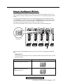
Wireless Test Mode
You can determine sound clarity, signal strength, and voice quality using Wireless Test Mode.
You should use Wireless Test Mode to help you locate the best place to install the radio
module(s) to optimize the performance of your MDW 9030P Pocketphone. Repeat the tests
several times, with the radio module positioned in a different location each time.
By performing the tests as you walk around the area in which the handset will be used, you can
determine the handset’s range and the voice quality throughout the area of coverage. To perform
the tests, all you need is an electrical outlet for the radio module and a charged battery
pack in the handset. You can perform the tests multiple times and in any order; and you
can exit at any time by pressing O.
NOTE:
Ignore anything that displays if you press 4 or 5 while in Wireless Test Mode. These
displays are for Lucent Technologies technicians’ use only.
1. Make sure the handset is turned off.
2. Press and hold the Select button (") for three seconds.
3. While still holding
" , press O.
The handset beeps twice, and the display shows the handset settings, indicating you
are in Local Mode. (While in Local Mode, the MDW 9030P can still receive notification
of incoming calls.)
4. Press "W" (9) to enter Wireless Test Mode.
WIRELESS TEST appears on the top line of the handset display.
ON
The handset beeps twice and vibrates, then you hear a simulated dial tone. This dial
tone continues until you exit Wireless Test Mode. While in this mode, the MDW 9030P
cannot make or receive calls.
5. To determine sound clarity, listen to the simulated dial tone as you walk around.
A clear, steady tone indicates good sound clarity.
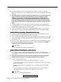
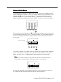
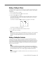
6. To determine signal strength, press 1.
The display shows the signal strength (SIG) for both the handset (HS) and the base (B)
(the radio module) at the moment that 1 was pressed, using a number from 1 to 10, as
shown in the following display.
ON
Installing the MDW 9030P Pocketphone 2-11
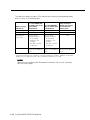
The higher the number, the stronger the signal, as shown in the following table. You
can press 1 again to show a subsequent signal-strength reading. Each time you
press 1, you get a new reading.
Display Number
Signal Strength Is
10
Strong
9
Strong
8
Strong
7
Very good
6
Very good
5
Good
4
Good to Fair
3
Fair
2
Near end of range
1
Near end of range/loss of link
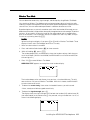
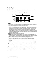
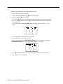
7. To determine voice quality, press 2.
The display shows the voice quality (QUAL) for both the handset (HS) and the base (B)
(the radio module) using a number from 1 to 10, as shown in the following display.
ON
The higher the number, the better the voice quality, as shown in the table below. A low
number may indicate potential interfering devices (such as another radio transmitter) in
the area. You can press 2 again to show a subsequent voice-quality reading. Each
time you press 2, you get a new reading.
Display Number
Voice Quality Is
10
Very good
9
Very good/almost error free
8
Errors, but not noticeable in
normal speech
7
Errors, but not noticeable in
normal speech
6
Noticeable noise
5
Noticeable noise
4
Noisy but intelligible speech
3
Noisy but intelligible speech
2
Garbled speech
1
Unintelligible speech
8. To exit Wireless Test Mode and Local Mode, press O.
2-12 Installing the MDW 9030P Pocketphone
Go to one of the following sections:
■ If installing one MDW 9030P Pocketphone, go to “Installing a Single Radio
Module.”
■ Otherwise, go to “Setting the Power Level.”
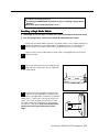
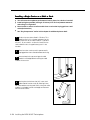
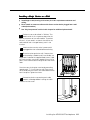
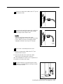
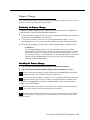
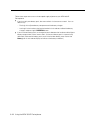
Installing a Single Radio Module
■
Install high on wall, leaving 6–12 inches (15.2–30.5 cm) between antenna and ceiling
■
See “Key Components” earlier in this chapter for additional picture detail
1
2
Perform the tests described in "Wireless Test Mode" earlier in this chapter to determine
the optimal placement of the radio module. To perform the tests, all you need is an
electrical outlet for the radio module and a charged battery pack in the handset.
Check to make sure the radio module’s power cord is unplugged from the wall outlet
before continuing.
the rubber feet from the shipping card.
3 Detach
Apply them to marked areas on the underside
of the radio module.
4
Place the wall-mounting plate against the wall.
Choose a location backed by a wooden stud (if
unavailable, use toggle bolts instead of the supplied
wood screws). Lightly tap a nail into the wall to start
holes. Then screw the plate flush to the wall. Place
the radio module over the plate, then slide it downward to lock it into place. (Note: Do not remove the
plastic cap covering the radio module’s card
edge.)
4
Screw
Holes
Installing the MDW 9030P Pocketphone 2-13
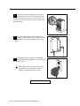
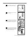
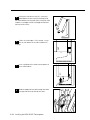
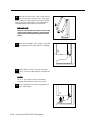
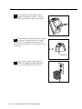
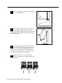
Insert one end of the telephone line cord into
an extension jack or terminal/station connector
on your communications system switch/control unit
(refer to your communications system manual for the
proper location).
5
X
N
T
S
E
I
N
O
S
N
I
S
O
N
MUSIC
ON
HOLD
S
PFT
L
I
N
E
PFT
L
S
I
N
E
S
PFT
L
PAGE
I
N
SMDR
E
PFT
L
S
I
N
E
PFT
L
S
I
206
N
MODULE
E
S
206
PFT
MODULE
E
PFT
PROCESSOR
MODULE
X
T
E
N
S
I
O
N
S
400
E
MODULE
X
T
E
400
VOL
MODULE
N
S
E
I
O
N
S
MUSIC
ON
HOLD
X
T
E
N
S
I
O
N
S
E
X
T
E
N
S
I
O
N
S
6 Insert the radio module’s power cord into the
side of the radio module. Insert the other end of
the telephone line cord into the bottom of the radio
module.
7 Plug the power cord/AC adapter into a properly
grounded 3-prong wall outlet that is not controlled
by an on/off switch.
!
CAUTION: Never connect or disconnect
the telephone line cord while the radio
module is plugged into the wall outlet.
Go to “Installation Self-Test.”
2-14 Installing the MDW 9030P Pocketphone
dio
Ra ule
d
Mo WER
PO
IO
RAD
SS
PA
Setting the Power Level
If you are installing one or more carriers in a strip mall, high-rise office building, or similar
environment, the MDW 9030P Pocketphones may interfere with other wireless products in
use.
■
If this is the case, you may need to adjust the range of the carriers to prevent
overlapping with the other wireless products; follow the instructions in this section.
■
If this is not the case, skip this section and go to “Setting the Control/Expansion DIP
Switch.”
2
2
1
1
O N
O N
1
O N
You may adjust the range by setting each carrier’s power DIP switch, located in Slot 2:
Power
DIP Switch
1
2
3
4
5
Slot 2
Installing the MDW 9030P Pocketphone 2-15
Use a nonmetallic, pointed object to set each carrier’s DIP switch according to the
following table.
IMPORTANT:
You must set the DIP switch for all of the carriers to the same setting.
Desired Range (Approximate)
Power DIP Switch Settings
O N
500 to 900 feet
(152 to 274 m)
O N
300 to 500 feet
(91 to 152 m)
O N
150 to 300 feet
(46 to 91 m)
O N
100 to 150 feet
(31 to 46 m)
Go to one of the following sections:
■ If installing multiple carriers, go to “Setting the Control/Expansion DIP Switch.”
■ Otherwise, go to “Installing a Single Carrier on a Shelf or Desk” or “Installing a
Single Carrier on a Wall.”
2-16 Installing the MDW 9030P Pocketphone
Setting the Control/Expansion DIP Switch
You must follow the instructions in this section if you are installing multiple carriers. Otherwise, skip to “Installing a Single Carrier on a Shelf or Desk” or “Installing a Single Carrier on
a Wall.”
If you are installing multiple carriers, you must designate one carrier (the leftmost carrier)
as the control carrier and the remaining carriers as expansion carriers. The control carrier
acts as the “lead” carrier—its transmit and receive patterns control the expansion carriers,
ensuring that all of the linked carriers function as a single system.
2
2
1
1
O N
O N
1
O N
You set the control/expansion DIP switch, located in Slot 4, to configure the carrier:
Control/Expansion
DIP Switch
1
2
3
4
5
Slot 4
Use a nonmetallic, pointed object to set each carrier’s DIP switch according to the following
table.
IMPORTANT:
Only one carrier (the leftmost carrier) can be the control carrier; the other carriers must be
expansion carriers.
To designate the carrier as a...
Use this setting for the DIP switch...
expansion carrier (one or two
additional carriers)
O N
O N
control carrier (one carrier only)
Go to “Installing Multiple Carriers.”
Installing the MDW 9030P Pocketphone 2-17
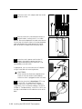
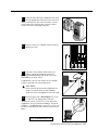
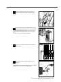
Installing a Single Carrier on a Shelf or Desk
■
You will not receive optimum performance if unit is placed on a desk or low shelf
■
Install as high as possible, leaving 6–12 inches (15.2–30.5 cm) between antennas
and ceiling if on high shelf
■
Never install or remove a radio module from a carrier that is plugged into a wall
outlet (hot insertion)
■
See “Key Components” earlier in this chapter for additional picture detail
1 Perform the tests described in "Wireless Test
Mode" earlier in this chapter to determine the
optimal placement of the radio module. To perform
the tests, all you need is an electrical outlet for the
radio module and a charged battery pack in the
handset.
Check to make sure the carrier’s power cord is
2 unplugged from the wall outlet before continuing.
Remove the plastic cap covering each radio
3 module’s card edge before installing the radio
modules in the carrier.
Starting from the leftmost slot (#1), insert each
radio module into the carrier by hooking it onto
the radio module mounting rod. Slowly swing the radio
module's card edge into the card edge connector on
the back of the carrier.
4
2-18 Installing the MDW 9030P Pocketphone
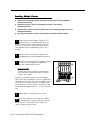
5
When the card edge is fully seated, a snap lock on
the bottom of the radio module will engage.
6
Insert a telephone line cord into the bottom of
each radio module.
the telephone line cords through the rear
7 Slide
exit slots on the bottom of the carrier. Cords
originating from Modules 1 and 6 can share exit slots
with cords from Modules 2 and 5 respectively.
Insert the free end of the telephone line cord
into the appropriate extension jack or terminal/
station connector on your communications system
switch/control unit (refer to your communications
system manual for the proper location).
8
N
S
I
O
N
S
X
T
E
N
S
I
O
N
MUSIC
ON
HOLD
S
PFT
L
I
N
E
PFT
L
S
I
N
E
S
PFT
L
PAGE
I
N
SMDR
E
PFT
L
S
I
N
E
PFT
L
S
I
206
N
MODULE
E
S
206
PFT
MODULE
E
PFT
PROCESSOR
MODULE
X
T
E
N
S
I
O
N
S
400
E
MODULE
X
T
E
400
VOL
MODULE
N
S
E
I
O
N
S
MUSIC
ON
HOLD
X
T
E
N
S
I
O
N
S
E
X
T
E
N
S
I
O
N
S
Installing the MDW 9030P Pocketphone 2-19
9 Insert the carrier’s AC adapter cord into the left
O N
1
2
3
10 Place the carrier on its feet towards the back of
the shelf or desk, making sure it is in a stable
position. Be sure the telephone line cords come out the
rear exit slots in the back of the unit. Arrange the power
cord and telephone line cords beneath the shelf or
desk so no one can step on them or trip over them.
11 Insert the carrier’s power cord into the AC
adapter, then plug the power cord into a
properly grounded 3-prong wall outlet that is not
controlled by an on/off switch.
If appropriate, you can wall-mount the AC adapter
using its attached wall-mounting bracket.
!
CAUTION:
Never connect or disconnect telephone line
cords, or insert or remove radio modules,
while the carrier is plugged into the wall outlet.
12 Verify that the carrier’s Out of Sync LED is not
lit. If the LED is lit, power down and then
repower the carrier. If the LED is still lit, follow the
suggestions in the "Installation Problems" section of
Chapter 5, "Troubleshooting." If the LED is still lit, call
for help as described on the inside front cover of this
book.
OUT
4
T RANS TALK
2
2
1
O N
1
O N
N
CAUTIO
ONLY
USECABLE
AT&T
847667896
P⁄N
IN
OUT
OUT
Go to “Installation Self-Test.”
2-20 Installing the MDW 9030P Pocketphone
1
2
3
4
5
6
OF SYNC
OUT
NC
FO SY
4
1 2
side of the carrier.
5
Installing a Single Carrier on a Wall
■
Install high on wall, leaving 6–12 inches (15.2–30.5 cm) between antennas and
ceiling
■
Never install or remove a radio module from a carrier that is plugged into a wall
outlet (hot insertion)
■
See “Key Components” earlier in this chapter for additional picture detail
1 Perform the tests described in "Wireless Test
Mode" earlier in this chapter to determine the
optimal placement of the radio module. To perform
the tests, all you need is an electrical outlet for the
radio module and a charged battery pack in the
handset.
2 Check to make sure the carrier’s power cord is
unplugged from the wall outlet before continuing.
Place the carrier against the wall. Choose a location backed by a wooden stud (if unavailable, use
toggle bolts instead of the supplied wood screws). Hold
the carrier straight; use a level if needed. Using a nail or
pencil, mark screw locations through the four wall-mount
holes.
3
4
T RANS TALK
2
Start the screws, leaving the screw heads protruding
approximately 1/2" (12 mm) from the wall. Place the carrier assembly over the screws, then slide it downward to
lock it into place. Tighten the screws.
2
1
O N
1
O N
ON
CAUTI
ONLY
USECABLE
6
AT&T 6789
8476
P⁄N
IN
OUT
1
2
3
4
5
OUT
C
OF SYN
6
4 Remove the plastic cap covering each radio
module’s card edge before inserting the radio
modules into the carrier.
Installing the MDW 9030P Pocketphone 2-21
5 Starting from the leftmost slot (#1), insert each
radio module into the carrier by hooking it onto
the radio module mounting rod. Slowly swing the radio
module's card edge into the card edge connector on
the back of the carrier.
When the card edge is fully seated, a snap
lock on the bottom of the radio module will
engage.
6
7
Insert a telephone line cord into the bottom of
each radio module.
8
Slide the telephone line cords through the cable
manager slot on the left front of the carrier.
2-22 Installing the MDW 9030P Pocketphone
9 Insert the free end of each telephone line cord
X
N
T
S
E
I
into the appropriate extension jack or terminal/
station connector on your communications system
switch/control unit (refer to your communications
system manual for the proper location).
N
O
S
N
I
S
MUSIC
ON
HOLD
O
N
S
PFT
L
I
N
PFT
E
L
S
I
N
E
S
PFT
L
PAGE
I
N
SMDR
E
PFT
L
S
I
N
E
PFT
L
S
I
206
N
MODULE
E
S
206
PFT
MODULE
PFT
E
PROCESSOR
MODULE
X
T
400
E
E
MODULE
X
N
T
S
E
I
400
VOL
MODULE
N
O
S
N
E
I
S
O
N
S
MUSIC
ON
HOLD
X
T
E
E
X
N
T
S
E
I
N
O
S
N
I
S
O
N
S
10 Plug the carrier’s AC adapter cord into the left
O N
1
2
3
4
1 2
side of the carrier.
5
11 Insert the carrier’s power cord into the AC
adapter, then plug the power cord into a
properly grounded 3-prong wall outlet that is not
controlled by an on/off switch.
If appropriate, you can wall-mount the AC adapter
using its attached wall-mounting bracket.
!
CAUTION:
Never connect or disconnect telephone line
cords, or insert or remove radio modules,
while the carrier is plugged into the wall outlet.
12 Verify that the carrier’s Out of Sync LED is not
lit. If the LED is lit, power down and then
repower the carrier. If the LED is still lit, follow the
suggestions in the "Installation Problems" section of
Chapter 5, "Troubleshooting." If the LED is still lit, call
for help as described on the inside front cover of this
book.
OUT
4
OUT
YNC
OF S
T RANS TALK
2
2
1
O N
1
O N
N
CAUTIO
ONLY
USECABLE
AT&T
847667896
P⁄N
IN
OUT
OUT
Go to “Installation Self-Test.”
1
2
3
4
5
OF SYNC
6
Installing the MDW 9030P Pocketphone 2-23
Installing Multiple Carriers
■
Install each carrier high on wall, leaving 6–12 inches (15.2–30.5 cm) between
antennas and ceiling
■
Install each carrier 1 foot (0.3 m) optimal to 4 feet (1.2 m) from its
neighboring carrier
■
Never install or remove a radio module from a carrier that is plugged into a wall
outlet (hot insertion)
■
See “Key Components” earlier in this chapter for additional picture detail
1 Perform the tests described in "Wireless Test
Mode" earlier in this chapter to determine the
optimal placement of the radio module. To perform
the tests, all you need is an electrical outlet for the
radio module and a charged battery pack in the
handset.
2 Check to make sure the carrier’s power cord is
unplugged from the wall outlet before continuing.
a location backed by a wooden stud for
3 Choose
the carrier (if unavailable, use toggle bolts
4
T RANS TALK
instead of the supplied wood screws).
IMPORTANT:
The leftmost carrier must be the control carrier.
See "Setting the Control/Expansion DIP Switch"
earlier in this chapter.
Place the carrier against the wall, leaving enough
room to the right for additional carrier(s) if applicable.
Hold the carrier straight; use a level if needed. Using a
nail or pencil, mark screw locations through the four
wall-mount holes. Start the screws, leaving the screw
heads protruding approximately 1/2" (12 mm) from the
wall.
4 Repeat Steps 1 through 3 for each carrier.
4
Place the carrier over the screws, then slide it
5 downward to lock it into place. Be sure that the
leftmost carrier is the control carrier. Tighten the
screws. Repeat for each carrier.
2-24 Installing the MDW 9030P Pocketphone
2
2
1
O N
1
O N
ON
CAUTI
ONLY
USECABLE
6
AT&T 6789
8476
P⁄N
IN
OUT
1
2
3
4
5
6
OUT
C
OF SYN
4 Connect an expansion cable to the OUT jack of
6 the control carrier.
ION
CAUT
IN
OUT
OUT
YNC
OF S
Insert the free end of the expansion cable into
7 the IN jack of the expansion carrier immediately to the right of the control carrier.
ION
CAUT
NOTE:
Although installing an expansion cable
into the wrong IN or OUT jack will not harm either
carrier, doing so causes all handsets to work
improperly and the Out of Sync LED to light.
IN
OUT
OUT
YNC
OF S
From
Control
Carrier
8 If you have a second expansion carrier:
a. Connect an expansion cable to the OUT jack
of expansion carrier #1.
b. Insert the free end of the expansion cable
into the IN jack of expansion carrier #2.
See “Key Components” earlier in this chapter for an
illustration of a three-carrier setup.
9 Remove the plastic cap covering each radio
module’s card edge before inserting the radio
modules into the carriers.
Installing the MDW 9030P Pocketphone 2-25
10 Working from left to right, insert a radio module
into each slot of the control carrier, starting with
Slot 1; hook each radio module onto a mounting rod.
Slowly swing the radio module's card edge into the
card edge connector on the back of the carrier.
IMPORTANT:
Slot 6 of a carrier that has another carrier to the
right of it must always contain a radio module
to pass the synchronization signal to the next
carrier.
11 When the card edge is fully seated, a snap lock
on the bottom of the radio module will engage.
12 Repeat Steps 10 and 11 for each expansion
carrier, until each radio module is inserted into
a carrier.
NOTE:
Fill all six slots of the current carrier before
inserting radio modules into the next carrier.
13 Insert a telephone line cord into the bottom of
each radio module.
2-26 Installing the MDW 9030P Pocketphone
14 Slide the telephone line cords through the
cable manager slot on the left front of each
carrier.
15 Insert the free end of the telephone line cord
into the appropriate extension jack or terminal/
station connector on your communications system
switch/control unit (refer to your communications
system manual for the proper location).
N
S
I
O
N
S
X
T
E
N
S
I
MUSIC
ON
HOLD
O
N
S
PFT
L
I
N
PFT
E
L
S
I
N
E
S
PFT
L
PAGE
I
N
SMDR
E
PFT
L
S
I
N
E
PFT
L
S
I
206
N
MODULE
E
S
206
PFT
MODULE
PFT
E
PROCESSOR
MODULE
X
T
400
E
E
MODULE
X
N
T
S
E
I
400
VOL
MODULE
N
O
S
N
E
I
S
O
N
S
MUSIC
ON
HOLD
X
T
E
E
X
N
T
S
E
I
N
O
S
N
I
S
O
N
S
16 Plug an AC adapter cord into the left side of
O N
1
2
3
4
1 2
each carrier.
5
17 Insert each carrier’s power cord into its AC
adapter.
If appropriate, you can wall-mount each AC adapter
using its attached wall-mounting bracket.
Installing the MDW 9030P Pocketphone 2-27
18 Plug each carrier’s power cord into one of the
following power sources that is not controlled
by an on/off switch:
■
Properly grounded 3-prong wall outlets
■
Surge suppressor strip
Power the carriers as follows:
If the carriers are plugged into...
Then...
one surge suppressor strip
power the strip.
Result: All carriers will turn on simultaneously.
wall outlets
plug in the power for all carriers in this order:
4
T RANS TALK
!
2
3
4
5
2
1
2
O N
CAUTIO
ONLY
USECABLE
AT&T
847667896
P⁄N
IN
1
O N
2
O N
2
1
2
1
O N
1
N
CAUTIO
ONLY
USECABLE
AT&T
847667896
P⁄N
IN
OUT
OUT
T RANS TALK
N
ONLY
USECABLE
AT&T
847667896
P⁄N
IN
1
2
O N
N
CAUTIO
1
4
T RANS TALK
O N
4
OUT
OUT
OF SYNC
OUT
1
6
2
3
4
5
OF SYNC
OUT
1
6
2
3
4
5
Control
Carrier
Expansion
Carrier #1
Expansion
Carrier #2
1
2
3
OF SYNC
6
CAUTION:
Never connect or disconnect expansion cables or telephone line
cords, or insert or remove radio modules, while the carrier is
plugged into the wall outlet.
19 Verify that the carriers’ Out of Sync LEDs are
not lit. If an LED is lit, power down and then
repower the carriers as described in Step 18. If the
LED is still lit, follow the suggestions in the "Installation Problems" section of Chapter 5, "Troubleshooting." If the LED is still lit, call for help as described on
the inside front cover of this book.
OUT
4
T RANS TALK
2
2
1
O N
1
O N
N
CAUTIO
ONLY
USECABLE
AT&T
847667896
P⁄N
IN
OUT
OUT
1
Go to “Installation Self-Test.”
2-28 Installing the MDW 9030P Pocketphone
2
3
4
5
6
OF SYNC
OUT
YNC
OF S
Installation Self-Test
Upon installation, the POWER and PASS LEDs on each radio module will light. The radio
modules then initiate a 2-minute self-test and synchronization. If a radio module’s PASS LED
does not light, repower the module or its carrier. Refer to Chapter 5, “Troubleshooting,” if
the PASS LED still does not light.
NOTE:
The RADIO LED also may light upon installation; however, since the RADIO LED has no
significance during the self-test, ignore its operation.
The RADIO LED indicates a connection between the handset and the radio module; it
lights when the handset is being used as long as the battery pack in the handset is
charged.
Go to “Handset.”
Installing the MDW 9030P Pocketphone 2-29
Handset
This section explains how to install the handset battery pack, change the communications
system setting, and fill out the handset label.
Inserting and Removing the
Handset’s Battery Pack
1 To insert the battery pack into the handset,
insert the two small rectangular tabs located
along the bottom back edge of the handset into the
two rectangular holes along the bottom front edge of
the battery pack.
Rectangular tabs
Press the battery pack downward until it clicks
2 into place.
Spring latch
The battery pack must be charged prior to using the
handset. See “Battery Charger” later in this chapter
for instructions.
To remove the battery pack, slide the spring
3 latch upward (away from the battery pack).
While holding the latch up, grasp both sides of the
battery pack, then gently pull the battery pack upward
and out.
2-30 Installing the MDW 9030P Pocketphone
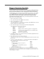
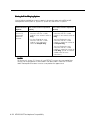
Changing the Communications System Setting
The communications system you use determines what information the MDW 9030P Pocketphone can display and how the phone lines and programmable/intercom/drop buttons are
identified (see "Button Mapping" in Chapter 6, "MDW 9030P Pocketphone Compatibility").
The MDW 9030P is factory-set to work with the PARTNER communications system. If you
are using PARTNER as your communications system, skip this section; if you are
using a different communications system, you will need to change the setting.
To change the communications system setting, use the following procedure to enter Local
Mode and then Button Mapping Mode:
1. Make sure the handset is turned off.
2. Press and hold the Select button (") for three seconds.
3. While still holding
" , press O.
The handset beeps twice, and the top line of the display shows LCL:P (unless you have
already changed it from the default setting).
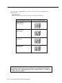
4. Press and hold "M" (6) for three seconds to enter Button Mapping Mode.
The handset display shows one of the following:
MAP:P
PARTNER systems
MAP:D
DEFINITY systems, System 25, System 75, and System 85
MAP:M1
All MERLIN systems (except MERLIN 410 and MERLIN 820),
including MERLIN LEGEND
MAP:M2
MERLIN 410 and MERLIN 820
5. Press " repeatedly to cycle through the settings until the display appropriate for your
communications system is shown.
6. Press O when the correct setting is displayed.
The top line of the display shows information appropriate to the communications system
you are using.
7. To verify your setting, repeat Steps 1–3. The top line of the display should appear as
follows, depending upon your communications system:
PARTNER systems:
LCL:P
DEFINITY systems, System 25, System 75,
LCL:D
and System 85
All MERLIN systems (except MERLIN 410 and
LCL:M1
MERLIN 820)
MERLIN 410 and MERLIN 820
LCL:M2
For a description of the button mapping between the MDW 9030P Pocketphone and the
wired telephones for your communications system, or to program features on buttons, see
"Button Mapping" in Chapter 6.
Installing the MDW 9030P Pocketphone 2-31
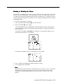
Filling Out the Handset Label
The MDW 9030P Pocketphone display shows the status of up to 12 lines or programmable/intercom/drop buttons. Since the MDW 9030P is compatible with several different
communications systems, diagrams of the button mapping for these systems are provided
in Chapter 6.
The MDW 9030P has a label on the back of the handset near the top where you can
record:
■
Your extension number
■
The mapping of your MDW 9030P line buttons to those on a wired phone for your
communications system
NOTE:
Use a pencil or ballpoint pen on the label, in case you want to erase the information
later. Do not use felt-tip or other types of non-erasable markers. Also, do not remove
the label.
EXT.
3
4
5
6
7
8
A
B
C
D
1
2
EX
T.
3
4
5
6
7
8
A
B
C
D
1
2
1 Write your extension number on the label.
2 Locate the section in Chapter 6 that describes the button mapping for your communications system; then copy the mapping to the label for ease of reference.
Go to “Battery Charger.”
2-32 Installing the MDW 9030P Pocketphone
Battery Charger
This section explains how to choose a location for the battery charger and install it. It also
explains how to insert and remove a battery pack.
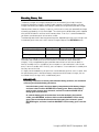
Positioning the Battery Charger
The battery charger can be placed on a desk, or it can be mounted on a wall. Before you
install the battery charger, note the following considerations:
■
Locate the battery charger within 5 feet (1.6 m) of a properly grounded 3-prong electrical
outlet that is not controlled by an on/off switch.
■
If your communications system uses an uninterruptable power supply, such as a
backup generator, you may want to connect the battery charger to that power supply.
■
Do not locate the battery charger where it will be exposed to direct sunlight or water.
WARNING:
The rechargeable battery pack may contain elements that are harmful to the
environment (for example, nickel). Do not burn or puncture the battery. Like other
batteries of this type, if it is burned or punctured, it could release toxic material
that could cause injury. Do not dispose of it in household garbage. For information
about recycling or proper disposal, consult your local solid waste (garbage)
collection or disposal organization.
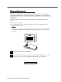
Installing the Battery Charger
■
If you are wall-mounting the battery charger, follow Steps 1 through 7
■
If you are desk-mounting the battery charger, follow only Steps 1, 5, and 7
1 Check to make sure the battery charger’s power cord is unplugged from the wall outlet
before continuing. If you are desk-mounting, skip to Step 5.
wall-mount, place the battery charger's wall-mounting template (located on the last
2 To
page of this book) against the wall. Choose a location backed by a wooden stud (if
unavailable, use toggle bolts instead of the supplied wood screws). Hold the template
straight; use a level if needed.
the locations for the two wall-mounting screws, and then remove the template
3 Mark
from the wall. Lightly tap a nail into the wall to start the holes.
4 Place the screw through the wall spacers so that the screw head nests in the indenta-
tion on the spacer. Start the screws, and screw them in until the wall spacers rest
against the wall.
Installing the MDW 9030P Pocketphone 2-33
5 Insert the battery charger’s power cord/AC
adapter into the battery charger. If you are
desk-mounting the battery charger, skip to Step 7.
4 Place the keyhole-shaped openings in the back
4 of the battery charger over the screw heads
6
and wall spacers, then slide the battery charger
downward into the groove in the wall spacers to lock
it into place.
the battery charger's power cord/AC
7 Plug
adapter into a properly grounded 3-prong wall
outlet that is not controlled by an on/off switch.
2-34 Installing the MDW 9030P Pocketphone
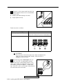
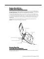
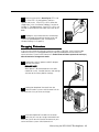
Inserting a Battery Pack into
the Spare Battery Compartment
Slide the battery pack into the Spare battery compartment until it is firmly seated with the
back of the battery pack against the back of the Spare battery compartment. Do not force
the battery pack down. The battery pack should slide easily into the slot.
Correct positioning of the battery pack in the charger is important to ensure proper charging. Note that the Spare battery compartment has a vertical ridge on each side that serves
as a "guide rail" for positioning the battery pack. The bottom end of the battery pack also
has two small round holes that match two guide pins on the bottom of the Spare battery
compartment.
When the battery pack is positioned correctly in the Spare battery compartment, the
SPARE LED on the front of the battery charger lights.
Vertical Guide Rail
Handset Cradle
Battery Charger Contacts
Spare Battery Compartment
Vertical Guide Rail
SPARE LED
Removing a Battery Pack
from the Spare Battery Compartment
To remove a battery pack from the Spare battery compartment of the charger, simply lift
the battery pack up and out.
Installing the MDW 9030P Pocketphone 2-35
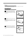
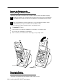
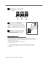
Inserting the Handset into the
Battery Charger's Handset Cradle
Correct positioning of the handset in the charger is important to ensure proper charging.
1 Position the handset (with its battery pack attached) so that the two small round holes
in the bottom of the handset fit over the two guide pins on the bottom of the handset
cradle.
2 Rock the handset back into the cradle until it is firmly seated with the back of the
handset battery pack against the back of the handset cradle.
When the handset has been inserted correctly, the following occur:
■
The HANDSET LED lights.
■
If the handset was turned on, the ON icon in the display is no longer visible.
■
Any call that was in progress is terminated.
■
After 15 seconds, the handset enters the energy-saving "sleep" mode.
On/Off
Redial
Feat/P
Conf
On/Off
Mute
1
2 ABC 3 DEF
Feat/P
4 GHI
Trans
Hold
5 JKL 6MN
O
7PQRS 8 TUV
9WXYZ
0OPER
Conf
Trans
Redial
2 C 3 DE
F
4 GHI 5 JK
L
6 MNO
7PQRS
Hold
SPAR
E
SPAR
E
HAN
HAN
AB
8 TUV 9 WXY
Z
0 OPER
DSE
DSE
Guide Pins
Mute
1
T
T
REFR
REFR
ESH
ESH
HANDSET LED
Removing the Handset
from the Handset Cradle
To remove the handset from the handset cradle, simply lift it out.
2-36 Installing the MDW 9030P Pocketphone
Using the MDW 9030P Pocketphone
3
Important Safety Instructions
Please see "Important Safety Instructions" at the beginning of Chapter 2.
The Handset
This section describes the handset and how to use it. It also explains how to use a headset.
Using the MDW 9030P Pocketphone 3-1
Handset Controls
Receiver
Headset On/Off
Receives the sound of your
caller's voice, unless a
headset is connected.
Press to turn the headset on if the
headset is plugged in. ON
appears in handset display. To
turn off, press again. Turn on to
make or answer a call, and turn off
to “hang up.”
Antenna
Extend fully or retract fully to
use handset. Extend fully to
maximize the handset range
and voice quality.
Lanyard Loop
Attach lanyard for carrying
handset.
Handset Display
Displays status of lines and
range. For a detailed
description, see “Handset
Display” later in this
chapter.
Volume Control
Press "+" to increase or "-" to
decrease volume of receiver or
alerter.
212
MSG
On/Off
555 1212
ON
5
6
7
8
1
2
3
4
A
B
C
D
Column
Use together with Select
button to choose a line or
programmable/intercom/
drop button.
Press to turn the handset on. ON
appears in handset display. To
turn off, press again. Turn on to
make or answer a call, and turn
off to “hang up.”
Redial
On/Off
Redial
Mute
1
2 ABC
3 DEF
Press to dial again the last
number manually dialed
from the handset.
Conf
4 GHI
5 JKL
6 MNO
Select
Trans
7PQRS
8 TUV
9 WXYZ
Feat/P (Feature/Program)
Press to use dial-code features
(PARTNER systems only) or to
enter programming mode.
Feat/P
Conf (Conference)
Press to conference in (add)
another party to your call.
Hold
0OPER
TransTalk
Use to move the Selection
rectangle, and, together
with Column buttons, to
choose a line or programmable/intercom/drop
button. Also use to wakeup the phone.
Trans (Transfer)
Press to transfer a call to
another extension.
Mute
Hold
Headset Connector
Press to put a call on hold.
Plug in the headset cord to
use the headset.
3-2 Using the MDW 9030P Pocketphone
Press to turn the microphone off for privacy .
Column and Select Buttons
The MDW 9030P Pocketphone can display the status of up to 12 lines or programmable/
intercom/drop buttons; however, it has only 4 selection buttons (the Column buttons). The
Select button (") is used in conjunction with the Column buttons (') to increase the
available selections to 12. Each Column button (') affects one of the three lines or
programmable/intercom/drop buttons directly above it, as shown in the illustration below.
ON
Each time you press the Select button ("), the Selection rectangle moves to another row
(cycling through the three rows in turn). The Column buttons (') each represent one of
the four lines or programmable/intercom/drop buttons in the row enclosed by the Selection rectangle.
ON
Selection rectangle
For example, suppose your handset shows the Selection rectangle around the middle row
of lines. If you press the second Column button from the left (shaded in the illustration
above), you select Line 2, as indicated by the truncated triangle in the illustration.
Note:
If you have a communications system other than PARTNER, the line you select is
indicated by a small rectangle instead of the triangle, as shown below:
ON
See "Manually Selecting a Line or Programmed Button" and "Preselecting a Line" later in
this chapter for more information about the Column and Select buttons.
Using the MDW 9030P Pocketphone 3-3
Handset Display
The MDW 9030P Pocketphone display has one 16-alphanumeric-character line, and four
lines of icons to provide you with status information.
3
4
5
6
1
MSG RANGE ON
2
8
MUTE
7
9
Note:
This illustration is intended to show you what all of the indicators look like, but you will
never see all of the line status indicators illuminated at once.
1
2
3
4
5
6
7
This line of the display gives you the information you would see on a wired system
phone's display, except that the time is not provided. The information varies according to which communications system you are using. For example, the display may
show the current date, the number you are calling, or caller ID information (if the
system supports this feature). This display line is also used for feedback when testing
and programming the handset. See "Display Messages" later in this chapter for more
information about messages.
MSG icon indicates that you have a message.
RANGE icon indicates that the handset is out of range or almost out of range. The
handset also beeps. For more information, see “Range Indicators” later in this chapter.
ON icon indicates that the handset has been turned on by pressing O.
Battery icon flashes to indicate a low battery condition. The handset also emits 2
beeps. For more information, see “Low Battery Indicator” later in this chapter.
No Ring icon indicates that the alerter is disabled. If the alerter is enabled, no icon is
displayed.
MUTE icon indicates that the handset microphone was turned off by pressing M.
Line Status Indicators show the status of line or programmable/intercom/drop buttons. See Chapter 6 for button-mapping information. Also see "Line Status Indicators"
later in this chapter.
9 Selection rectangle indicates the active row for line or programmable/intercom/drop
button selection. See "Column and Select Buttons" earlier in this chapter.
When the display is blank, the handset is either turned off or in the power-saving "sleep"
mode. You can activate the display by pressing O to turn the handset on or by
pressing " to "wake it up."
8
3-4 Using the MDW 9030P Pocketphone
Display Messages
The top line of the handset display uses up to 16 alphanumeric characters to provide
messages such as the following:
■
LCL:P (or LCL:D, LCL:M1, or LCL:M2) indicates that the handset is in Local Mode, and
tells which communications system the button mapping is set to emulate:
PARTNER systems
DEFINITY systems, System 25, System 75, and System 85
All MERLIN systems (except MERLIN 410 and MERLIN 820),
including MERLIN LEGEND
LCL:M2
MERLIN 410 and MERLIN 820
WIRELESS TEST indicates that the handset is in Wireless Test Mode; 1 through 10 are
used to measure signal strength and voice quality in Wireless Test Mode.
LCL:P
LCL:D
LCL:M1
■
■
VIBR indicates that the vibrator is enabled to notify you of incoming calls.
■
PSEL indicates that Line Preselection is enabled.
■
PRESELECTION:ON or PRESELECTION:OFF is displayed when you enter Preselection Mode, and indicates the status of the Line Preselection option.
■
CHANGE BUTTN MAP is an error message indicating that the handset is set for the
wrong communications system. See "Changing the Communications System Setting" in
Chapter 2 for instructions for changing the setting.
■
MAP:P (or MAP:D, MAP:M1, or MAP:M2) is displayed when you enter Button Mapping
Mode, and indicates the communications system to which the MDW 9030P buttons are
currently mapped:
PARTNER systems
DEFINITY systems, System 25, System 75, and System 85
All MERLIN systems (except MERLIN 410 and MERLIN 820),
including MERLIN LEGEND
MAP:M2
MERLIN 410 and MERLIN 820
NO LINK is an error message indicating that the handset is not communicating with its
radio module. See Chapter 5, "Troubleshooting," for help in resolving this problem.
MAP:P
MAP:D
MAP:M1
■
Line Status Indicators
There are 12 status indicators; each one corresponds to a specific outside line or programmable/intercom/drop button. (The function of these status indicators varies, depending on
the communications system you are using—see button mapping for the appropriate
communications system switch in Chapter 6, "MDW 9030P Pocketphone Compatibility.")
The status indicators show either a truncated triangle or a rectangle, signifying activity as
follows:
PARTNER Systems:
A rectangle (
) is the equivalent of a red LED on a wired system phone.
A truncated triangle (
) is the equivalent of a green LED on a wired system phone.
All Other Systems:
A rectangle (
) is the equivalent of a green LED on a wired system phone.
A truncated triangle (
) is the equivalent of a red LED on a wired system phone.
Using the MDW 9030P Pocketphone 3-5
Range Indicators
For maximum range and voice quality, always fully extend the antenna before placing or
answering a call. The antenna must be either fully retracted (for short range) or fully
extended (for maximum range) to use the Pocketphone.
The handset provides an audible and a visual signal to alert you when the handset is near
the end of the range of the radio module. Depending on how far away the handset is from
the radio module, the signals function as follows:
■
The handset emits two beeps and flashes the RANGE indicator continuously.
Out of optimal range. You have walked into an area that is near the end of the operating range of the radio module. You can continue your conversation or initiate a call, but
you are likely to experience a degradation in voice quality.
■
The handset emits five sets of beeps and displays the RANGE indicator.
Loss of communication link. You have walked into an area that is out of the operating
range of the radio module. You must bring the handset within range of the radio module
within several seconds or the handset will turn off. If the handset turns off, it appears
that your call was disconnected; however it was only placed on Hold. To talk with your
party, move back towards the radio module, press O, then proceed as you would
for any call placed on Hold.
■
When you try to make a call, the handset emits two beeps and flashes the RANGE
indicator twice; then the handset automatically turns off.
Cannot establish communication link. You are completely out of range of the radio
module. To make the call, move back towards the radio module and try again.
Refer to Chapter 5, “Troubleshooting,” for additional information about out-of-range conditions.
Low Battery Indicator
When the handset is On and the battery power is low, the handset will emit two beeps and
the Battery icon in the handset display will flash. When this occurs, you have 5 minutes or
less of talk time left. At this point, you can either:
■
Complete your call, turn the handset off, and recharge the battery pack, or
■
If you have a charged spare battery pack, place your call on Hold and replace the
handset battery pack with the spare battery pack. Wait 6 to 10 seconds, then turn the
handset on and proceed as you would for any call placed on Hold.
NOTE:
When the battery power is low, the two beeps will sound each time either O button
is pressed until either the battery is drained or you replace the battery. If you continue
talking, the handset will turn off when the battery pack is drained. Your call will be
placed on Hold automatically so that you can swap battery packs or pick up the call on
another telephone.
3-6 Using the MDW 9030P Pocketphone
Volume Control
To increase or decrease the volume of the handset alerter or the receiver (earpiece):
■
Alerter: Press the “+” or the “–” button while the MDW 9030P is awake but turned off.
If the display is dark (the phone is in "sleep" mode), press " to wake it up, then press
the “+” or the “–” button.
■
Receiver: Press the “+” or the “–” button while the MDW 9030P is turned on.
+
–
+ and – Volume Control Buttons
Lanyard Loop
Carrying Your Pocketphone
The MDW 9030P Pocketphone has a loop in the upper corner to accommodate the included
lanyard. You can attach the lanyard, as illustrated above, and slip the lanyard over your
wrist to guard against dropping the phone. A leather carrying case is also available
separately (see "Ordering Replacement & Optional Parts" in Chapter 4).
The MDW 9030P Pocketphone also comes with a detachable clip, which you can attach to
the back of the battery pack, that enables you to attach the phone to your belt or purse
strap. To attach the clip to the battery pack, do the following:
Remove the battery pack from the handset, as described in "Inserting and
Removing the Handset's Battery Pack" in
Chapter 2.
1
2 Place the two metal tabs on the clip into
the slots on the battery pack, with the
"hooks" toward the bottom of the battery pack.
3
Slide the clip toward the bottom of the
battery pack to engage the hooks.
4 Reinsert the battery pack in the handset,
as described in "Inserting and Removing
the Handset's Battery Pack" in Chapter 2.
Using the MDW 9030P Pocketphone 3-7
Antenna
The MDW 9030P Pocketphone comes with a user-replaceable, flexible, retractable antenna.
For maximum range and voice quality, always fully extend the antenna before placing or
answering a call. You can receive a call (if you are within range of the radio module) without
extending the antenna, but you may get a RANGE indication. The antenna must be fully
extended for optimal performance.
Changing the Handset Settings
You can use Local Mode to change the handset settings for these functions:
■
Communications system button mapping
■
Vibrator
■
Line Preselection
■
Alerter
Local Mode also gives you access to Local Test Mode (which enables you to test the
alerter, vibrator, and display) and Wireless Test Mode (which enables you to test sound
clarity, signal strength, and voice quality). While in Local Mode, the MDW 9030P can still
receive notification of incoming calls.
To access Local Mode, use the following procedure:
1. Make sure the handset is turned off.
2. Press and hold the Select button (") for three seconds.
3. While still holding
", press O.
The handset beeps twice, and the display shows the handset settings. For example,
the following display indicates that the handset:
■
Is using button mapping for a PARTNER switch
■
Has the vibrator and Line Preselection enabled
■
Has the alerter disabled
To exit Local Mode, press O.
Changing the Communications System Button Mapping Setting
If the MDW 9030P Pocketphone is set to use the wrong communications system, an error
message saying CHANGE BUTTN MAP shows on the top line of the handset display each
time the O button is pressed. If you see this message, use the procedure described
in "Changing the Communications System Setting" in Chapter 2 to specify the correct
communications system setting.
3-8 Using the MDW 9030P Pocketphone
Enabling or Disabling the Vibrator
The vibrator vibrates to alert you to an incoming call in situations where you do not want to
disturb others with an audible ring. You can enable or disable the vibrator using the following procedure:
1. Make sure the handset is turned off.
2. Press and hold the Select button (") for three seconds.
3. While still holding
", press O.
The handset beeps twice, and the display shows the handset settings, indicating that
you are now in Local Mode. (While in Local Mode, the MDW 9030P can still receive
notification of incoming calls.)
If the vibrator is enabled, the VIBR icon appears in the display. For example:
ON
If the vibrator is disabled, no icon appears.
4. Press "V" (8) on the dialpad to enable or disable the vibrator.
5. Press O to exit Local Mode.
Note:
Both the alerter and the vibrator can be disabled at the same time. In this case the only
notification you have of an incoming call is that a line status indicator (a truncated
triangle or a rectangle, depending on your communications system) flashes in the
display.
Enabling or Disabling Line Preselection
Line Preselection lets you choose the line or button you want to use before turning the
handset on. For example, suppose your phone is ringing but you want to pick up a call
that is holding on another line instead of the ringing call. In normal operation, the communications system automatically connects you to the ringing line as soon as you turn on the
handset. With Line Preselection enabled, you can select the line you want to connect to
before turning on the handset.
Note:
Under certain conditions, the communications system tries to turn on a speaker; for
example, if you use Line Preselection to select a button programmed for speed-dialing.
Since the MDW 9030P Pocketphone has no speaker, the system causes the ON icon in
the handset display to flutter. You must press O to complete the connection.
Note:
When Line Preselection is enabled, you do not have to use it; however you cannot use it
unless it is enabled.
Using the MDW 9030P Pocketphone 3-9
To enable Line Preselection, use the following procedure:
1. Make sure the handset is turned off.
2. Press and hold the Select button (") for three seconds.
3. While still holding
", press O.
The handset beeps twice, and the display shows the handset settings, indicating you
are in Local Mode. (While in Local Mode, the MDW 9030P can still receive notification
of incoming calls.)
If Line Preselection is enabled, PSEL shows on the top line of the display. For example:
If Line Preselection is disabled, no icon appears.
4. Press and hold "P" (7) for three seconds.
The handset display shows PRESELECTION:ON if Line Preselection is enabled or
PRESELECTION:OFF if Line Preselection is disabled. For example:
5. Press " to toggle between ON and OFF to enable or disable Line Preselection.
6. Press O to exit Local Mode.
3-10 Using the MDW 9030P Pocketphone
Enabling or Disabling the Alerter
The alerter is an audible signal to notify you of an incoming call. If a call comes in while the
phone is idle, the handset rings. If you are already on a call, the handset chirps softly. You
can adjust the volume of the alerter by pressing the "+" button or the "–" button on the side
of the handset when the phone is turned off. You can enable or disable the alerter using the
following procedure:
1. Make sure the handset is turned off.
2. Press and hold the Select button (") for three seconds.
3. While still holding
", press O.
The handset beeps twice, and the display shows the handset settings, indicating you
are in Local Mode. (While in Local Mode, the MDW 9030P can still receive notification
of incoming calls.)
If the alerter is disabled, the No Ring icon (a bell with a line through it) appears in the
second line of the display. For example:
ON
If the alerter is enabled, the icon is not displayed. For example:
ON
4. Press "A" (2) on the dialpad to enable or disable the alerter.
5. Press O to exit Local Mode.
Note:
Both the alerter and the vibrator can be disabled at the same time. In this case the only
notification you have of an incoming call is that a line status indicator (a truncated
triangle or a rectangle, depending on your communications system) flashes in the
display.
Using the MDW 9030P Pocketphone 3-11
Test Modes
You can use Local Test Mode and Wireless Test Mode to verify that your handset is
working properly and that the MDW 9030P system is performing optimally.
Using Local Test Mode
You can use Local Test Mode to activate the audio warning signal, the vibrator, and all
visual indicators on the handset display, enabling you to test the following:
■
Does the audio warning signal work?
■
Does the vibrator vibrate?
■
Is the display operational?
■
Are the visuals bright and clear?
Note:
While in Local Test Mode, the MDW 9030P cannot make or receive calls.
1. Make sure the handset is turned off.
2. Press and hold the Select button (") for three seconds.
3. While still holding ", press O.
The handset beeps twice, and the display shows the handset settings, indicating you
are in Local Mode. (While in Local Mode, the MDW 9030P can still receive notification
of incoming calls.)
4. Press # to enter Local Test Mode.
The handset emits two beeps, the vibrator vibrates, and all indicators on the display
appear (including the rectangles and truncated triangles), as shown below.
Local Test Mode
MSG RANGE ON
MUTE
If the beeps do not sound, the vibrator does not vibrate, or the indicators do not
appear, repeat Steps 1–4. If you still have problems, call for customer support as
described on the inside front cover of this book.
3. Press O once to exit both Local Test Mode and Local Mode.
You must exit Local Test Mode to reinstate proper call handling.
3-12 Using the MDW 9030P Pocketphone
Using Wireless Test Mode
You can determine sound clarity, signal strength, and voice quality using Wireless Test Mode.
You can also use Wireless Test Mode to identify which radio module matches your handset.
NOTE:
Ignore anything that displays if you press 4 or 5 while in Wireless Test Mode. These
displays are for Lucent Technologies technicians’ use only.
To identify the matching radio module for your handset, use the following procedure:
1. Make sure the handset is turned off.
2. Press and hold the Select button (") for three seconds.
3. While still holding
", press O.
The handset beeps twice, and the display shows the handset settings, indicating you
are in Local Mode. (While in Local Mode, the MDW 9030P can still receive notification
of incoming calls.)
4. Press "W" (9) to enter Wireless Test Mode.
WIRELESS TEST appears on the top line of the handset display. The handset beeps
twice and vibrates, then you hear a simulated dial tone. This dial tone continues until
you exit Wireless Test Mode. While in this mode, the MDW 9030P cannot make or
receive calls.
5. To identify the matching radio module for this handset, press 3.
The display indicates in which slot in the individual carrier (SLOT:n) the matching radio
module is located, using a number (n) from 1 to 6 . A stand-alone radio module is shown
as 0. For example:
ON
6. To exit Wireless Test Mode and Local Mode, press O.
Using the MDW 9030P Pocketphone 3-13
Performance/Range Test in Wireless Test Mode
Using the signal-strength test and the voice-quality test together, you can determine the
range in which your MDW 9030P Pocketphone performs best at your site:
At 10–15 feet (3.1–4.6 m) from its radio module, use the following procedure:
1. Make sure the handset is turned off.
2. Press and hold the Select button (") for three seconds.
3. While still holding
", press O.
The handset beeps twice, and the display shows the handset settings, indicating you
are in Local Mode. (While in Local Mode, the MDW 9030P can still receive notification
of incoming calls.)
4. Press "W" (9) to enter Wireless Test Mode.
WIRELESS TEST appears on the top line of the handset display. The handset beeps
twice and vibrates, then you hear a simulated dial tone. This dial tone continues until
you exit Wireless Test Mode. While in this mode, the MDW 9030P cannot make or
receive calls. For more information, see "Wireless Test Mode" in Chapter 2.
5. Press 1.
The display should show a 9 or 10 for signal strength. If it does not, see Chapter 5,
"Troubleshooting," for help with range problems.
6. Press
2.
The display should show a 9 or 10 for voice quality. If it does not, see Chapter 5,
"Troubleshooting," for help with range problems and/or voice quality problems.
7. Periodically check the signal strength and voice quality as you walk away from the radio
module. Each time you press 1 or 2, you get a new reading.
When you see a signal strength of 3, you are at the "edge of range" for the MDW 9030P
Pocketphone. The distance will vary depending on the environment, building structure,
and other factors. The range in an average office building is 500–700 feet (152.5–213.5
m). If, however, dense walls intervene, the distance could be less.
8. With a signal strength of 3, press 2 to check the voice quality. When the voice quality
is 7 or 8, the voice connection should be satisfactory. This is the edge of your usable
range.
The following diagram illustrates this Performance/Range test.
Close-Up Test
10 to 15 feet (3.1 to 4.6 m)
Signal Strength = 9 to 10
Voice Quality = 9 to 10
Edge-of-Usable-Range Test
Signal Strength = 3
Voice Quality = 7 to 8
3-14 Using the MDW 9030P Pocketphone
POWER
RADIO
PASS
Radio
Module
"Waking Up" the Phone
In addition to "On" and "Off," the MDW 9030P has an energy-saving "sleep" or "standby"
mode. The MDW 9030P "goes to sleep" 15 seconds after activity ceases (that is, after an
alert stops ringing or after you hang up).
The O and " buttons "wake up" the phone. The headset and handset O
buttons turn the phone on, and the Select button (") signals the phone that activity is
occurring. You can activate the display to see whether you have a message or to check
whether your alerter is enabled without actually turning the phone on (if the communications system is very busy, for instance) by pressing ".
Making a Call
To make a call using your MDW 9030P, use the following procedure:
1. Press the handset O button (or the headset O button if you have the headset
attached) to turn the phone on.
–
–
The MDW 9030P seizes an available line and a truncated triangle or a small rectangle (depending on your communications system) appears around that line in the
handset display.
You hear a dial tone.
2. Dial the call as you would on a wired system phone.
3. To end the call, press the O button.
After 15 seconds, unless there is other activity on the phone, the handset goes into the
energy-saving "sleep" mode.
Answering a Call
When you receive a call on your MDW 9030P Pocketphone, you hear a ringing tone if your
alerter is enabled, or you feel a vibration in the handset if the vibrator is enabled, or both.
To answer the call, use the following procedure:
1. Press the handset O button (or the headset O button if you have the headset
attached) to turn the phone on.
You are automatically connected to the ringing line.
4. Speak into the handset to converse with your caller.
5. To end the call, press the O button.
After 15 seconds, unless there is other activity on the phone, the handset goes into the
energy-saving "sleep" mode.
Using the MDW 9030P Pocketphone 3-15
Manually Selecting a Line or Programmed Button
When you are making or answering a call, the MDW 9030P automatically selects the line for
you. In some situations, however, you may want to select a particular line (for example, to
use an "800" line). To select a particular line or programmable/intercom/drop button, use
the following procedure:
1. Press O.
The ON icon displays steadily, and you are connected to an available line.
2. If the Selection rectangle in the handset display is not surrounding the row that includes
the line or button you want to use, press " one or more times until the rectangle
encloses that row. (See "Column and Select Buttons" earlier in this chapter for more
information.)
3. Press the ' button that corresponds to the line or button within the Selection rectangle
that you want to select.
You are connected to the line or you have access to the button you chose.
To deselect the line or button, press O.
For information about assigning features to buttons, see "Programming Features for PARTNER, MERLIN, and MERLIN LEGEND Systems" in Chapter 6.
Preselecting a Line
You may sometimes want to select a line other than the line to which the communications
system automatically connects you. To preselect a line, you must first enable Line
Preselection. See "Enabling or Disabling Line Preselection" earlier in this chapter.
Once Line Preselection is enabled, use the following procedure:
1. If the handset is "asleep," press " to wake it up and activate the display.
2. If the Selection rectangle in the handset display is not surrounding the row that includes
the line you want to use, press " repeatedly until the rectangle encloses that row.
(See "Column and Select Buttons" earlier in this chapter for more information.)
3. Press the ' button that corresponds to the line within the Selection rectangle that you
want to select.
The ON icon flashes in the display and the handset emits double beeps.
4. Press O.
The ON icon displays steadily, and you are connected to the line you chose.
3-16 Using the MDW 9030P Pocketphone
Using a Headset
Lucent Technologies offers the Supra 9030 headset, which is specifically designed for
use with your MDW 9030P wireless phone. A headset assists in call answering, and
provides hands-free operation.
For ordering information, see "Ordering Replacement & Optional Parts" in Chapter 4.
To use the Supra 9030 headset, hold its cord with the "UP" label facing you, and insert the
plug directly into the headset connector on the bottom of the handset (near the mouthpiece).
CAUTION:
Plug ONLY the Supra 9030 headset cord into the headset connector.
NOTE:
Calls cannot be heard on the handset receiver when the headset is plugged in to the
headset connector. The handset microphone is also deactivated. The range of the handset
is slightly diminished when you are using a headset. You may need to move closer to
the radio module, or move the radio module closer to you.
If desired, you can disconnect the headset from the handset without dropping the call. Just
unplug the headset cord from the handset. You can then use the handset as you normally
would.
Using the Headset On/Off Button
The headset On/Off button near the antenna becomes active only when the headset is
plugged into the headset connector. The headset On/Off button is identical in function to the
O button near the dialpad.
Answering Calls with a Headset
When you receive a call, you will hear a ringing tone or feel a vibration coming from the
handset (you will not hear a tone from the headset itself). To answer the call, press either
the headset On/Off button near the antenna or the O button near the dialpad.
Using the MDW 9030P Pocketphone 3-17
Placing Calls with a Headset
To place a call with a headset:
1. Press the On/Off button near the antenna or the
access an available line.
O button near the dialpad to
The microphone and earpiece in the handset are disabled.
2. Dial the call as you would on a wired system phone.
3. Press either the On/Off button near the antenna or the O button near the dialpad
to end the call.
3-18 Using the MDW 9030P Pocketphone
The Battery Charger
The battery charger charges battery packs in the Spare battery compartment and in the
handset. If both are present at the same time, charging in the Spare battery compartment
is suspended until the battery pack in the handset is fully charged. To enable extended
phone usage, you should purchase an extra battery pack and store it in the charger, so
that you always have a charged battery pack to switch to, if necessary. This section
describes the battery charger and explains how to use battery packs properly.
Spare Battery
Compartment
Guide Rail
Handset
Cradle
Spare Battery
Compartment
Battery Contacts
REFRESH Button
REFRESH LED
Handset Cradle
Battery Contacts
Spare Battery
Compartment
HANDSET LED
SPARE LED
NOTE:
Do not touch, push, or pull any exposed battery contacts.
Battery Charger Features
The battery charger offers these features:
■
The Spare battery compartment refreshes the battery pack automatically by fully
discharging it before recharging it. This process reduces or eliminates the potential
“memory” effect. Memory effect, which reduces a battery’s capacity, occurs over time
when you repeatedly recharge a battery before it is fully discharged.
■
The handset cradle charges a battery pack in the handset.
■
The REFRESH button, when pressed, refreshes the handset battery pack in the
handset cradle by fully discharging the battery pack before recharging it.
■
The REFRESH LED and the HANDSET LED light when the REFRESH button is pressed
and stay lit until the battery pack finishes discharging.
■
The HANDSET LED, when lit, indicates that the handset battery pack is installed in the
handset, and the handset is in the handset cradle.
■
The SPARE LED, when lit, indicates that a battery pack is in the Spare battery compartment.
Using the MDW 9030P Pocketphone 3-19
The color of the battery charger's LEDs indicates the state of the corresponding battery
pack, as shown in the following table:
Battery charger
LED shows...
If it is the SPARE LED,
the battery pack in the
Spare battery
compartment...
If it is the HANDSET
LED, the battery pack
in the Handset...
If it is the REFRESH
LED, the Refresh
button was pressed,
and the Handset
battery pack...
Steady orange
Is charging
Is charging
N/A
Steady green
Is fully charged
Is fully charged
N/A
Flashing red
Has one of the
following problems:
Has one of the
following problems:
N/A
• Is not seated
properly in the
charger
• Is not seated
properly in the
charger
• Has dirty contacts
• Has dirty contacts
• Is defective
• Is defective
Is in the Discharge
portion of the Refresh
cycle.
Is in the Discharge
portion of the Refresh
cycle.
* See note.
Steady red
Is in the Discharge
portion of the Refresh
cycle.
*Note: If either the SPARE LED or the HANDSET LED is flashing red, both battery packs
must be removed from the charger to clear the flashing-red condition. Address the possible
problems for one battery pack at a time to determine whether one is bad.
NOTE:
Before you use the MDW 9030P Pocketphone handset for the first time, the battery
pack must be charged.
3-20 Using the MDW 9030P Pocketphone
Extending Battery Life
The battery charger will charge a battery pack in the handset if you simply insert the
handset in the battery charger's handset cradle; however, the Refresh process fully discharges the battery pack before recharging it, thereby ensuring the best possible charge.
"Memory effect" reduces a battery's capacity, and can occur when you repeatedly recharge
a battery pack before it is fully discharged. The nickel metal hydride battery pack shipped
with your MDW 9030P is resistant to the memory effect. Even so, it is recommended that
you refresh your battery pack at least once a week.
The following table shows how long refreshing takes, depending on how much charge is left
in the battery pack when you insert it into the charger and press the REFRESH button:
Battery-Pack Charge State
Discharge Time
Recharge Time
Total Time
Low charge (Battery icon is
lit)
0.5 hours
1 hour
1.5 hours
Full charge
3 hours
1 hour
4 hours
Note that your handset will consume power during both talk time (when the handset is
turned on) and standby time (when the handset is turned off, but out of the battery
charger). A fully charged battery pack provides about 3 hours of talk time or about 22
hours of standby time. As a guideline, you can expect a 1-hour reduction in talk time for
every 7 hours of standby time. Similarly, you can expect a 7-hour reduction in standby time
for every hour of talk time.
It is highly recommended that you purchase a second battery pack to use as a spare. With
the spare battery pack in the Spare battery compartment of the battery charger, you are
assured of always having a fresh, usable battery pack.
IMPORTANT:
Depending on the level of memory effect that the battery pack has, it is sometimes
necessary to refresh the battery pack twice:
Insert the battery pack in the Spare battery compartment of the battery charger
and leave it there until the SPARE LED is steady green. Remove the battery
pack from the charger, then reinsert it, and leave it until the SPARE LED is
steady green a second time.
Or, with the battery pack in the handset, insert the handset in the handset
cradle, press REFRESH, and leave it there until the HANDSET LED is steady
green. Remove the handset from the handset cradle, then reinsert it, press
REFRESH again, and leave it until the HANDSET LED is steady green a second
time.
Using the MDW 9030P Pocketphone 3-21
Follow these steps to ensure an uninterrupted supply of power to your MDW 9030P
Pocketphone:
■
If you have only one battery pack, be sure to refresh it at least once a week. You can
refresh it by:
– Placing it in the Spare battery compartment of the battery charger.
– Leaving it in the handset, placing the handset in the handset cradle of the battery
charger, and pressing the REFRESH button.
■
If you have two battery packs, exchange the packs between the handset and the Spare
battery compartment at least once a week, so that each battery pack is automatically
refreshed. (Alternate the battery packs even if the handset battery never flashes the
Battery icon in the handset display to indicate a low battery condition.)
3-22 Using the MDW 9030P Pocketphone
Maintaining the MDW 9030P Pocketphone
4
Impor
tant Safety Instr
uctions
Important
Instructions
Please see "Important Safety Instructions" at the beginning of Chapter 2.
Removing a Radio Module
fr
om the Car
rie
from
Carrie
rierr
See “Key Components” in Chapter 2 for additional picture detail.
Slot 6 of a carrier that has another carrier to the right of it must always contain a
radio module to pass the synchronization signal to the next carrier.
■
■
1
Unplug the carrier(s) power cord/AC adapter
from the wall outlet.
IMPORTANT:
When power is disconnected from the radio
module or carrier, handset features and settings
are reset to the factory default settings.
2 Unplug the telephone line cord from the bottom
of the radio module.
Maintaining the MDW 9030P Pocketphone 4-1
3
Press up and hold the snap lock on the bottom
rear of the radio module.
Slowly swing the radio module's card edge out of
the card edge connector on the back of the
carrier, releasing the snap lock when clear. Unhook the
radio module from the radio module mounting rod by
gently lifting upward.
4
If you removed a radio module from Slot 6 of a
carrier that has another carrier to the right of it,
you must insert another radio module into this slot.
Slot 6 of any carrier must always be filled if there is
another carrier to the right of it. Failure to do so will
cause the carriers to be unsynchronized.
5
Repower the carrier. If you have multiple
carriers, repower them in order from left to right,
as shown below:
6
4
2
3
4
5
6
2
CAUTI
2
O N
ONLY
USECABLE
6
AT&T
84766789
P⁄N
IN
1
O N
2
O N
2
1
2
1
O N
1
ON
CAUTI
ONLY
USECABLE
6
AT&T
84766789
P⁄N
IN
OUT
OUT
T RANS TALK
ON
ONLY
USECABLE
6
AT&T
84766789
P⁄N
IN
1
2
O N
ON
CAUTI
1
4
T RANS TALK
O N
T RANS TALK
1
4
OUT
OF SYNC
OUT
1
2
3
4
5
6
OUT
OF SYNC
OUT
1
2
3
4
5
Control
Carrier
Expansion
Carrier #1
Expansion
Carrier #2
1
2
3
4-2 Maintaining the MDW 9030P Pocketphone
6
OF SYNC
Verify that the carrier’s Out of Sync LED is not
lit. If the LED is lit, power down and then
repower the carrier. If the LED is still lit, follow the
suggestions in the "Installation Problems" section of
Chapter 5, "Troubleshooting." If the LED is still lit, call
for help as described on the inside front cover of this
book.
7
4
8
T RANS TALK
2
2
O N
ONLY
USECABLE
AT&T
847667896
P⁄N
IN
1
O N
N
CAUTIO
1
Reprogram any handset features and settings
that reverted to the default settings when the
system was powered down (see "Changing the
Handset Settings" in Chapter 3).
OUT
OUT
YNC
OF S
OUT
OUT
1
2
3
4
5
OF SYNC
6
Swapping Extensions
If you want to change your phone’s extension number assignment, make sure the radio
module or carrier(s) is unplugged before you unplug the telephone line cord from the
communications system switch/control unit. Power down and then repower the carrier(s)
after all extension changes are made.
1
Unplug the carrier(s) power cord/AC adapter
from the wall outlet.
IMPORTANT:
When power is disconnected from the radio
module or carrier, handset features and settings
are reset to the factory default settings.
2 Unplug the telephone line cords from the
communications system switch/control unit for
the extensions that you want to change.
N
S
I
O
N
S
X
T
E
N
S
I
O
N
MUSIC
ON
HOLD
S
PFT
L
I
N
E
PFT
L
S
I
N
E
S
PFT
L
PAGE
I
N
SMDR
E
PFT
L
S
I
N
E
PFT
L
S
I
206
N
MODULE
E
S
206
PFT
MODULE
E
PFT
PROCESSOR
MODULE
X
T
E
N
S
I
O
N
S
400
E
MODULE
X
T
E
400
VOL
MODULE
N
S
E
I
O
N
S
MUSIC
ON
HOLD
X
T
E
N
S
I
O
N
S
E
X
T
E
N
S
I
O
N
S
3 Insert the telephone line cords for the exten-
sions that you want to change into the desired
extension jack or terminal/station connector on your
communications system switch/control unit.
Maintaining the MDW 9030P Pocketphone 4-3
Repower the carrier. If you have multiple
carriers, repower them in order from left to
right, as shown below:
4
4
2
3
4
5
6
2
CAUTI
2
O N
ONLY
USECABLE
6
AT&T
84766789
P⁄N
IN
1
O N
2
O N
2
1
2
1
O N
1
ON
CAUTI
ONLY
USECABLE
6
AT&T
84766789
P⁄N
IN
OUT
OUT
T RANS TALK
ON
ONLY
USECABLE
6
AT&T
84766789
P⁄N
IN
1
2
O N
ON
CAUTI
1
4
T RANS TALK
O N
T RANS TALK
1
4
OUT
OF SYNC
OUT
1
2
3
4
5
OUT
OF SYNC
6
OUT
1
2
3
4
5
Control
Carrier
Expansion
Carrier #1
Expansion
Carrier #2
1
2
3
Verify that the carrier’s Out of Sync LED is not
lit. If the LED is lit, power down and then
repower the carrier. If the LED is still lit, follow the
suggestions in the "Installation Problems" section of
Chapter 5, "Troubleshooting." If the LED is still lit, call
for help as described on the inside front cover of this
book.
OF SYNC
6
5
4
6
T RANS TALK
2
2
O N
ONLY
USECABLE
AT&T
847667896
P⁄N
IN
1
O N
N
CAUTIO
1
Reprogram any handset features and settings
that reverted to the default settings when the
system was powered down (see "Changing the
Handset Settings" in Chapter 3).
OUT
OUT
YNC
OF S
OUT
OUT
1
2
3
4
5
OF SYNC
6
Replacing the Antenna
If the antenna on your MDW 9030P Pocketphone handset becomes damaged, you can
order a replacement antenna (see "Ordering Replacement & Optional Parts" later in this
chapter), and replace it yourself.
To replace the antenna, use the following procedure:
1. Fully retract the antenna.
2. Grasping the base of the antenna, unscrew it by turning it counterclockwise.
3. Grasping the base of the new antenna, screw it into the handset in a clockwise
direction.
4-4 Maintaining the MDW 9030P Pocketphone
Ordering Replacement & Optional Parts
To order replacement parts or optional equipment in the continental U.S., call the
Sourcebook Sales, Catalog Sales, or National Parts Sales Center toll free. When ordering,
please use the part numbers shown in the table below:
Item
Sourcebook
Catalog
Sales
Sales
1 800 451-2100 1 800 635-8866
National Parts
Sales Center
1 800 222-PART
MDW 9030P Pocketphone (StandAlone). Includes Radio Module and
Kit of Parts
3204-05B
3204-05B
107733081
(for Pocketphone)
107586828
(for Kit of Parts)
MDW 9030P Pocketphone System
(requires Carrier). Includes Radio
Module, but not Kit of Parts
3204-W5B
3204-W5B
107733081
Retractable Flex Antenna for
MDW 9030P Pocketphone Handset
NA
NA
847713450
Battery Pack. Includes Carrying Clip
32045A
32045A
107733107
Carrying Clip
NA
NA
847773140
Lanyard
NA
NA
407183417
MDW 9030P Pocketphone Leather
Carrying Case
32043A
32043A
847877487
Power Cord/AC Adapter for Radio
Module (11 foot (3.4 m))
NA
NA
847523404
Battery Charger. Includes Power
Cord/AC Adapter
32047A
32047A
107733099
Power Cord/AC Adapter for Battery
Charger (11 foot (3.4 m))
NA
NA
847713583
Carrier—Includes:
■ Power Cord and AC Adapter for
Carrier (25 foot (7.6m))
■ Expansion Cable for MultipleCarrier Installation (6 foot (1.8m))
3204-CR2A
3204-CR2A
107503906
NA
NA
847224227
Expansion Cable for Multiple-Carrier
Installation (6 foot (1.8 m))
32035A
32035A
847667870
Telephone Line Cord (8 foot (2.4 m))
NA
NA
103786794
Supra® 9030 Headset
3122-042A
3122-042A
407654490
Kit of Parts (for Stand-Alone
MDW 9030P Installation)
D-182866
D-182866
107586828
Power Cord and AC Adapter for
Carrier (25 foot (7.6 m))
Outside the continental U.S., contact your Lucent Technologies Representative or local
Authorized Dealer.
Maintaining the MDW 9030P Pocketphone 4-5
Troubleshooting
5
Procedures
If you have a problem with your MDW 9030P Pocketphone, you may be able to solve it by
following the procedures included in this chapter. If you cannot resolve the problem, call
for customer support as described on the inside front cover of this book.
The problems in this chapter are organized as follows:
■
Installation
■
Handset
■
Battery
■
Voice Quality
■
Range
■
Battery Charger
Installation Problems
Symptom
Possible Causes
One or more Out of
Sync LEDs are lit,
radio module PASS
LEDs are not lit, or
both.
Expansion cable is installed
1. Verify that all expansion cables
in the wrong IN or OUT jack,
are installed in the correct IN
or is not fully inserted into the
and OUT jacks.
correct jack.
2. Ensure that all expansion
cables are fully inserted into
their jacks.
Carriers were not powered in
3.
Power down, then repower the
the correct order.
control carrier.
4. Power down, then repower the
A telephone line cord was
expansion carriers in order, from
disconnected and reconleft to right.
nected without powering
down and repowering the
carrier(s).
Possible Solutions
Troubleshooting 5-1
Installation Problems (continued)
Symptom
Possible Causes
Possible Solutions
After plugging the
radio module or
carrier into an
electrical outlet, one
or more radio module
POWER and PASS
LEDs do not light.
Radio module or carrier(s) is
plugged into an electrical
outlet controlled by a switch.
Plug the radio module or
carrier(s) into an outlet not
controlled by a switch.
Power cord of radio module
is not inserted properly.
Unplug the radio module’s
power cord/AC adapter from
the electrical outlet and from
the radio module. Carefully
reinsert the power cord/AC
adapter into the radio module
and into the electrical outlet.
Repeat for each radio module.
Power cord of carrier(s) is
not inserted properly.
Unplug the carrier’s power
cord from the electrical outlet.
Unplug the AC adapter from
the carrier and from the power
cord. Carefully reinsert the AC
adapter into the carrier and
into the power cord. Plug the
power cord back into the
electrical outlet. Repeat for
each carrier.
Power cord of radio module
or carrier(s) is defective.
Call for help.*
Radio modules are not
synchronized properly.
Power down the carrier and
repower it. If you have multiple
carriers, repower the control
carrier first, and then power the
expansion carriers in order from
left to right.
After plugging the
radio module into an
electrical outlet, the
radio module’s
POWER LED lights,
but the PASS LED
does not light.
If the problem persists, call for
help.*
The radio module is malfunctioning.
* See “Customer Support” on the inside front cover of this book.
5-2 Troubleshooting
Replace the radio module.
Installation Problems (continued)
Symptom
Possible Causes
Possible Solutions
After plugging the
carrier into an
electrical outlet, the
PASS LED of one or
more radio modules
does not light.
Radio modules are out of
synchronization.
Power down the carrier and
repower it. If you have multiple
carriers, repower the control
carrier first, and then power the
expansion carriers in order from
left to right.
If the problem persists, call for
help.*
A radio module is malfunctioning.
1. Remove all but one radio
module from the carrier. (See
"Removing a Radio Module
from the Carrier" in Chapter 4.)
2. Test each radio module individually, verifying that the
POWER and PASS LEDs on
each radio module light when
the carrier is powered.
3. If the PASS LED does not light,
the radio module is malfunctioning. Replace the radio module
and handset.
A defective radio
module was
replaced, and now
all the handsets
have less range
than before, and
the voice quality
has deteriorated.
The radio module was inserted without first powering
down the carrier. The carrier
is out of synchronization.
When turned on,
the handset
display shows
lines going on hold
and line selections
changing without
any buttons being
pressed.
Electrical outlets may not be
up to specifications. Electrical problems, such as no
ground or floating ground,
can cause the switch to send
or receive spurious current,
causing problems in switch
protocol.
Power down the carrier and
repower it. If you have multiple
carriers, repower the control
carrier first, and then power the
expansion carriers in order from
left to right.
If the problem persists, call for
help.*
Verify that the outlets for the
communications system switch
and for the carrier(s) meet
electrical requirements. (See
"AC Outlet Check" in Chapter 2.
* See “Customer Support” on the inside front cover of this book.
Troubleshooting 5-3
Handset Problems
Symptom
Possible Causes
Possible Solutions
After pressing
O, one or more
of the following
applies:
There is no battery pack in
the handset.
Insert a battery pack in the
handset.
Battery pack is not inserted
properly in the handset.
Reinsert the battery pack in the
handset.
Battery pack is not charged
sufficiently.
Place the handset with its battery
into the handset cradle until fully
charged, or remove the handset
battery pack, and place it in the
battery charger’s Spare battery
compartment until fully charged.
If you have a charged battery
pack, use it while the other
battery pack recharges.
Handset is out of range of its
matching radio module.
Move the handset closer to the
radio module.
Telephone line cord is not
plugged into the radio
module.
Power down the radio module or
carrier(s). Plug the telephone
line cord into the radio module,
then repower the radio module
or carrier(s).
Serial numbers for the handset and the radio module do
not match.
The handset and radio module
must be a matched pair.
The communications system
switch is not operating
properly.
Check the wiring for the switch,
and verify that the switch has
power.
Another electrical device or
metal walls are causing
interference.
Remove the electrical device
that is causing interference, or
move the handset or the radio
module to another location.
■
Dial tone is not
heard.
■
Display does not
show anything.
■
Radio module's
RADIO LED does
not light.
There was a recent occurrence of lightning or a
power failure.
5-4 Troubleshooting
■
Remove the battery pack from
the handset for 10 seconds,
then replace it.
■
Check to see whether the radio
module or carrier is receiving
power.
Handset Problems (continued)
Symptom
Possible Causes
Possible Solutions
You can hear the
party on the other
end, but they cannot
hear you. MUTE
appears in the
handset display.
The M button was
pressed inadvertently.
Press M again to turn off the mute
feature.
When placed in
the battery
charger's handset
cradle, the
handset does not
turn off.
Battery charger is
plugged into an electrical outlet controlled by
a switch, and the
switch is turned off.
Plug the battery charger into an outlet
not controlled by a switch.
Battery charger's power 1. Unplug the power cord/AC adapter
cord is not inserted or is
from the electrical outlet.
not inserted properly.
2. Disconnect the power cord/AC
adapter from the battery charger.
3. Carefully reconnect the power cord/
AC adapter to the battery charger.
4. Plug the power cord/AC adapter
back into the electrical outlet.
Handset does not
ring or vibrate.
Alerter is disabled and
vibrator is disabled.
Enable the alerter and/or the vibrator.
Troubleshooting 5-5
Battery Problems
Symptom
Possible Causes
Possible Solutions
The Battery icon appears in the handset
display.
This is normal operation
for the MDW 9030P
Pocketphone.
No action is required.
The Battery icon flashes
in the handset display
and the handset beeps
twice.
Battery power is low.
You have 5 minutes or less of
talk time left. Either:
■ Complete your call, turn the
handset off, and recharge the
battery pack.
■ If you have a fully charged
spare battery pack, place your
call on Hold. Swap the battery
packs. Wait 6 to 10 seconds,
then turn the handset on and
proceed as you would for any
call placed on Hold.
The handset battery
pack does not last as
long as it used to under
similar conditions.
The battery pack needs to
be refreshed.
When the Battery icon flashes,
insert the handset with its
battery into the handset cradle
and press the REFRESH
button, or insert the handset
battery pack into the Spare
battery compartment until the
SPARE LED is steady green (1.5
hours).
You get less than 3 hours
of talk time when you use
a battery pack that was
refreshed.
The battery pack needs to
be refreshed a second
time.
Refresh the battery pack.
5-6 Troubleshooting
Voice Quality Problems
Symptom
Handset voice
quality and range
are not as good
as they were
before.
Possible Causes
A competing radio
device (for example, a
wireless bar-code
scanner) has been
installed in the area.
Both products are
competing for the
same air space and
will conflict when both
are being used.
Possible Solutions
Place the handset in Wireless Test Mode
as described in Chapter 2. If the signal
strength and voice quality readings are
low, look for a newly installed radio
device nearby. Remove it or move your
handset’s matching radio module at least
6 feet (1.8 m) away from the potential
interference.
Radio modules are out For a single-carrier installation, power
down, then repower the carrier.
of synchronization.
For a multiple-carrier installation:
1. Verify that all expansion cables are
installed in the correct IN and OUT
jacks.
2. Verify that all expansion cables are fully
inserted into their jacks.
3. Power down, then repower the control
carrier.
4. Power down, then repower the expansion
carriers in order, from left to right.
Antenna of the radio
module is too close to
the ceiling.
Reinstall the radio module or carrier(s) so
that the radio module antenna is 6–12
inches (15.2–30.5 cm) from the ceiling.
You have a malfunctioning radio module.
1. Remove all but one radio module from
the carrier. (See "Removing a Radio
Module from the Carrier" in Chapter 4.)
2. Test each radio module individually,
verifying that the POWER and PASS
LEDs on each radio module lights when
the carrier is powered.
3. If the PASS LED does not light, the
radio module is malfunctioning. Replace the radio module and handset.
Voice quality in a
specific location
is poor and noisy.
Handset is too close to
the carrier(s).
Move the handset at least 6 feet (1.8 m)
away for a one- or two-carrier setup, or
10 feet (3.1 m) away for a three-carrier
setup.
Troubleshooting 5-7
Voice Quality Problems (continued)
Symptom
Possible Causes
Voice quality for calls is The handset antenna is
lower than expected.
only partially extended.
Volume is too low at
any setting and there
is noise on the line.
Your business has two
or more wireless
phones installed and
all handsets seem to
have developed
interference problems
at the same time.
5-8 Troubleshooting
Possible Solutions
Fully extend the handset antenna.
There are environmental
limitations.
Reinstall the radio module or
carrier away from electrical
equipment and as high as
possible on the wall (but with
radio module antennas 6–12
inches (15.2–30.5 cm) from the
ceiling). See “General Positioning Rules” in Chapter 2 for more
information.
You are using different
models of handsets and
the mix is incompatible
with the carrier.
See "TransTalk 9000 System" in
Chapter 1.
Handset or radio
module is not
working properly.
Place the handset in Wireless
Test Mode and determine signal
strength and voice quality as
described in Chapter 2. Use the
Close-Up Test described in
"Performance/Range Test in
Wireless Test Mode" in Chapter 3.
The connection
between the radio
module and the
communications
system switch/control
unit is incorrect.
Check the connection between
the radio module and the communications system switch/control
unit, as described in Chapter 2.
Telephone line may
be producing noise.
Report line trouble to your local
phone company.
There was a recent
occurrence of
lightning, or a power
failure.
1. Unplug the carrier(s) power
cord(s) from the electrical
outlet.
2. Wait 10 seconds, then repower
the carrier(s) in order, from left
to right.
Voice Quality Problems (continued)
Symptom
Possible Causes
Possible Solutions
You are on a call
and you hear radio
interference when
another call rings.
Communications
system in key mode
has all lines set to
ring. An incoming
call “wakes up” all of
the other radio
modules at the same
time to ring the other
phones.
Refer to Chapter 6, “MDW 9030P
Pocketphone Compatibility,” to reset line
ringing options.
Voice quality for a
call in progress
degrades for more
than 6 seconds
(PARTNER, PARTNER Plus, PARTNER II in key
mode, MERLIN,
MERLIN Plus, and
MERLIN II phone
systems only).
Line ringing options
are incorrectly set for
extensions with radio
modules in the first
expansion carrier.
Refer to Chapter 6, “MDW 9030P
Pocketphone Compatibility,” to reset line
ringing options.
Troubleshooting 5-9
Range Problems
Symptom
Handset voice quality
and range are not as
good as they were
before.
Possible Causes
Possible Solutions
A competing radio
device (for example, a
wireless bar-code
scanner) has been
installed in the area.
Both products are
competing for the same
air space and will
conflict when both are
being used.
Place the handset in Wireless Test
Mode as described in Chapter 2. If
the signal strength and voice
quality readings are low, look for a
newly installed radio device
nearby. Remove it or move your
handset’s matching radio module
at least 6 feet (1.8 m) away from
the potential interference.
Radio modules are out
of synchronization.
For a single-carrier installation,
power down, then repower the carrier.
For a multiple-carrier installation:
1. Verify that all expansion cables
are installed in the correct IN and
OUT jacks.
2. Verify that all expansion cables
are fully inserted into their jacks.
3. Power down, then repower the
control carrier.
4. Power down, then repower the
expansion carriers in order, from
left to right.
Antenna of the radio
module is too close to
the ceiling.
You have a malfunctioning radio module.
Reinstall the radio module or
carrier(s) so that the radio module
antenna is 6–12 inches (15.2–30.5
cm) from the ceiling.
1. Remove all but one radio module
from the carrier. (See "Removing a
Radio Module from the Carrier" in
Chapter 4.)
2. Test each radio module individually, verifying that the POWER and
PASS LEDs on each radio module
light when the carrier is powered.
(Continued on next
page)
5-10 Troubleshooting
3. If the PASS LED does not light,
the radio module is malfunctioning.
Replace the radio module and
handset.
Range Problems (continued)
Symptom
Possible Causes
Possible Solutions
Electromagnetic fields
are interfering.
Look for 110/Volt lines, fuse boxes,
circuit breakers, electrical junction
boxes, or similar items. Move the
carrier or radio module at least 6
feet (1.8 cm) away from the potential
interference.
There is a large metal
object within 3 feet
(1.2 m) of the radio
module.
Move the carrier or radio module at
least 3 feet (1.2 m) away from the
potential interference.
There is a large metal
object in the "line of
sight" to the radio
module.
Move the metal object, or move the
carrier or radio module.
After pressing O to
turn the handset on,
the handset beeps and
RANGE shows in the
handset display.
Handset is out of range
of its matching radio
module.
Move the handset closer to the
radio module.
An electrical device is
interfering with your
communications link.
Remove the interfering device or
power it off, or move the handset
to another location.
Range for calls is
lower than expected.
The handset antenna is
only partially extended.
Fully extend the handset antenna.
There are environmental
limitations.
Reinstall the radio module or
carrier away from electrical
equipment and as high as possible on the wall (but with radio
module antennas 6–12 inches
(15.2–30.5 cm) from the ceiling).
See “General Positioning Rules” in
Chapter 2 for more information.
(Continued)
Handset voice quality
and range are not as
good as they were
before.
You are using different
See "TransTalk 9000 System" in
models of handsets and Chapter 1.
the mix is incompatible
with the carrier.
Troubleshooting 5-11
Range Problems (continued)
Symptom
Possible Causes
Possible Solutions
No ring on an incoming
call, and RANGE appears
in handset display.
Handset is out of range of
its matching radio module.
Move the handset closer to the radio
module.
While you are talking and
walking, the handset
beeps and RANGE
flashes in the handset
display.
Handset antenna is not
fully extended.
Fully extend the handset antenna.
You are approaching an
out-of-range condition.
Move back towards the handset’s
matching radio module until the
display stops showing RANGE.
While talking and
walking, the handset
beeps and RANGE
flashes in the handset
display. You keep
walking away from the
handset’s matching radio
module, the display
goes blank, and your call
appears to be disconnected.
You are out of range of the
radio module. YOUR CALL
HAS NOT BEEN DISCONNECTED. IT HAS BEEN
PLACED ON HOLD.
Move back towards the radio
module. Press O, then proceed
as you would for any call placed on
Hold.
After placing a call on
Hold, you walk away
from the handset’s
matching radio module.
Your handset beeps, the
handset display flashes
RANGE, and your call
appears to be disconnected.
You are out of range of the
radio module. YOUR CALL
HAS NOT BEEN DISCONNECTED. IT IS STILL ON
HOLD.
Move back towards the radio
module. Press O, then proceed
as you would for any call placed on
Hold.
5-12 Troubleshooting
Battery Charger Problems
Symptom
Possible Causes
No LEDs on battery
charger light.
Battery charger is plugged
into an electrical outlet
controlled by a switch and
the switch is turned off.
HANDSET LED on
Handset is not seated
battery charger does not properly in battery
light when handset is
charger's handset cradle.
placed in battery charger.
Possible Solutions
Plug the battery charger into
an outlet not controlled by a
switch.
Reseat the handset in the
battery charger's handset
cradle, as described in Chapter 3.
The contacts in the hand- 1. Verify that there are no
obstructions on the handset
set cradle or on the battery
or battery charger contacts.
pack are dirty.
2. Unplug the charger and
clean the contacts with a soft
eraser.
3. Clean the handset contacts
with a soft eraser.
The battery pack is defective.
If you have a fully charged
spare battery pack, use it to
replace the battery pack in the
handset.
1. Place the questionable battery
pack in the battery charger’s
Spare battery compartment.
2. Wait one minute. If the
SPARE LED flashes red, order
a new battery pack.
Troubleshooting 5-13
Battery Charger Problems (continued)
Symptom
Possible Causes
Possible Solutions
HANDSET LED flashes
red.
Battery pack is defective.
If you have a battery pack in
the handset and one in the
Spare battery compartment,
remove both battery packs
from the charger to clear the
red flashing LED. Then test
each battery pack separately
as follows:
1. Place the battery pack in the
battery charger’s Spare battery
compartment.
2. Wait one minute. If the
SPARE LED flashes red, order
a new battery pack.
The contacts in the hand- 1. Verify that there are no
set cradle or on the battery
obstructions on the handset
pack are dirty.
or battery charger contacts.
2. Unplug the charger and
clean the contacts with a soft
eraser.
3. Clean the handset contacts
with a soft eraser.
Handset is not seated
properly in battery
charger's handset cradle.
5-14 Troubleshooting
Reseat the handset in the
battery charger's handset
cradle, as described in Chapter 3.
Battery Charger Problems (continued)
Symptom
Possible Causes
SPARE LED on battery
charger does not light
when the battery pack is
placed in Spare battery
compartment.
The battery pack is not
seated properly in Spare
battery compartment.
Possible Solutions
Reseat the battery pack in the
battery charger’s Spare battery
compartment.
The contacts on the battery 1. Verify that there are no
obstructions on the battery
pack or in the Spare
pack or battery charger
battery compartment are
contacts.
dirty.
2. Unplug the charger and
clean the contacts with a soft
eraser.
3. Clean the battery pack
contacts with a soft eraser.
The battery pack is defective.
1. Insert the questionable battery
pack in the handset and place
the handset in the handset
cradle.
2. Wait one minute. If the HANDSET LED flashes red, order a
new battery pack.
Troubleshooting 5-15
Battery Charger Problems (continued)
Symptom
Possible Causes
SPARE LED flashes red. Battery pack is defective.
Possible Solutions
If you have a battery pack in
the handset and one in the
Spare battery compartment,
remove both battery packs
from the charger to clear the
red flashing LED. Then test
each battery pack separately
as follows:
1. Insert the battery pack in
handset and place the handset
in the battery charger’s
handset cradle.
2. Wait one minute. If the
HANDSET LED flashes red,
order a new battery pack.
The contacts on the battery 1. Verify that there are no
obstructions on the battery
pack or in the battery
pack or battery charger
charger's Spare battery
contacts.
compartment are dirty.
2. Unplug the charger and
clean the contacts with a soft
eraser.
3. Clean the battery pack
contacts with a soft eraser.
The battery pack is not
seated properly in Spare
battery compartment.
5-16 Troubleshooting
Reseat the battery pack in the
battery charger’s Spare battery
compartment, as described in
Chapter 3.
MDW 9030P Pocketphone Compatibility
6
Programming and
Call Handling Instructions
The MDW 9030P Pocketphone can display the status of up to 12 telephone lines, but the
number of lines supported by compatible communications system switches varies. After
you have installed your MDW 9030P and understand the controls and displays, use the
programming and call handling instructions that come with your communications system;
follow the user instructions for the phone type identified below:
For this release
Of this communications system...
Use the instructions for a...
R1, R2, R3, R4
PARTNER®
MLS-12D phone*
R1, R3, R4
PARTNER® II
(Apparatus code 7311H)
R1, R2, R3, R4
PARTNER® Plus
FP 1&2
MERLIN® (206, 410)
BIS-22D phone
FP 2
MERLIN® (820)
(Apparatus code 7315H)
FM 1, 2, 3, 4, & 5
MERLIN® (1030, 3070)
FM 1, 2, R3
MERLIN® II
R1, R2
MERLIN® Plus
R1, R1.1, R2,
R2.1, R3
MERLIN LEGEND®
R1V1, R1V2, R2,
System 25
R3V1, R3V2, R3V3
R1V1, R1V2, R1V3 System 75
R2V1, R2V2,
R2V3, R2V4
System 85
G1, G2, G3
DEFINITY®
Legend: R=Release, V=Version, FP=Feature Package, FM=Feature Module, G=Generic
* PARTNER Plus or PARTNER II Release 4.1 communications system users can order documentation for MLS telephones by calling 1 800 457-1235 or 1 317 361-5353 and asking for Order
Number 107794331.
MDW 9030P Pocketphone Compatibility 6-1
NOTE:
The MDW 9030P Pocketphone is fully compatible with the PARTNER family of communication systems. For the remaining communications systems, however, you must
carefully note the functional differences between your wireless phone and the phone
type identified in the table on the previous page. Differences are summarized on the
following pages.
Some systems do not support display features. In these cases, the display is not
available; the MDW 9030P works as a nondisplay set.
Programming Features for PARTNER,
MERLIN, and MERLIN LEGEND Systems
On all PARTNER, MERLIN, and MERLIN LEGEND systems, you can assign a feature to an
available button (a button that does not have a line or another feature assigned to it):
1. To enter programming mode, turn on the handset, press i, then press
followed by 0 0.
/
2. Press the Select button (") to move the Selection rectangle to the row of line indicators containing the available button.
3. Press the Column button (') under the button that you want.
4. Program the feature (using the procedure described in the manual for your PARTNER,
MERLIN, or MERLIN LEGEND communications systems).
NOTE:
Some features provide a visual indication in the handset display that the feature is
turned on. Be aware that if you turn off the handset while using one of these features,
you may forget that the feature is on. To verify the status of a such a feature, you can
simply press the " button to "wake up" the phone and activate the display.
5. To exit programming mode, press / followed by 0 0 or turn off the handset.
NOTE:
The above instructions do not apply to System 25, System 75, System 85, and
DEFINITY systems, because in those systems, features are assigned by the System
Administrator.
6-2 MDW 9030P Pocketphone Compatibility
Communications System Compatibility
This section describes some communications-system-dependent programming to help
you optimize the performance of your MDW 9030P Pocketphone. It also describes how
the buttons on a wired phone for your communications system map to the buttons on
your MDW 9030P. Turn to the information appropriate to your communications system:
■
PARTNER
■
MERLIN
■
System 25, System 75, System 85, and DEFINITY
PARTNER Systems
Button Mapping for PARTNER Systems
On PARTNER systems, the MDW 9030P emulates an MLS-12D telephone. Following is a
diagram of the button assignments on an MLS-12D phone and the corresponding
assignments on the MDW 9030P Pocketphone.
MLS-12D
09/10 TUE
10:24a
C
D
5
6
1
2
Intercom
Intercom
A
B
7
8
3
4
Ext.
Volume
Speakerphone
Spkr
Conf
Transfer
D
5
6
7
8
1
2
3
4
Intercom
Intercom
A
Mic
HFAI
Message
B
Volume
ABC
DEF
1
2
3
GHI
JKL
MNO
4
5
6
PQRS
TUV
WXYZ
7
8
9
0
#
Feature
C
Ext.
Speakerphone
Spkr
Mic
HFAI
Hold
212
MSG
5
On/Off
555 1212
ON
6
7
8
1
2
3
4
A
B
C
D
Redial
Mute
1
2 ABC
3 DEF
Conf
4 GHI
5 JKL
6 MNO
Trans
7PQRS
8 TUV
9 WXYZ
Feat/P
Hold
0OPER
TransTalk
MDW 9030P Pocketphone Compatibility 6-3
Setting the Line-Ringing Options
Use the following guidelines to ensure optimal voice quality when using MDW 9030P
Pocketphones with a PARTNER, PARTNER Plus, or PARTNER II system in key mode:
Telephone
System with Two Carriers
Communications (one control and one expansion
System
carrier)
System with Three Carriers
(one control and two expansion
carriers)
PARTNER
Not applicable: PARTNER
supports up to 12 phones.
1. Set Line Ringing for each
extension that has a radio
module in the control carrier to
Ring.
2. Set Line Ringing for each
extension that has a radio
module in the expansion
carrier to No Ring. (Install an
external audible alert for these
extensions.)
PARTNER Plus,
PARTNER II
1. Set Line Ringing for each
extension that has a radio
module in the control carrier to
Ring.
1. Set Line Ringing for each
extension that has a radio
module in the control carrier to
Ring.
2. Set Line Ringing for each
extension that has a radio
module in the expansion
carrier to Delayed Ring.
2. Set Line Ringing for each
extension that has a radio
module in expansion carrier #1
to Delayed Ring.
3. Set Line Ringing for each
extension that has a radio
module in expansion carrier #2
to No Ring. (Install an external
audible alert for these
extensions.)
NOTE:
For PARTNER II hybrid systems that use pooled lines, set the Line Ringing options as
described in the above table if more than six MDW 9030P Pocketphone handsets have
the same pooled line appearance.
6-4 MDW 9030P Pocketphone Compatibility
MERLIN Systems
■
On MERLIN II and MERLIN LEGEND systems, you must connect your wireless phone
to an available jack on either a 408 outside line/analog telephone module or a 008
analog telephone module.
■
Since the MDW 9030P does not have a speaker function, the Voice Announce feature
must be disabled. It is recommended that you use MERLIN 206/410/820 systems
installed with Feature Package 2 with your wireless phone, so that you can disable that
feature.
■
Since the MDW 9030P has no speaker function, it should not be assigned to a paging
group.
■
To program the Ringing Option feature, use the “triangle” and “rectangle” indicators
in the display as the equivalent of red and green LEDs, respectively.
■
For MERLIN II system users, if you program an Auto Intercom button, idle line preference
must be set to intercom.
■
If any of your incoming lines has the call waiting feature, use the Recall feature (letter "C" in
the display) and press it before you pick up a waiting call. You can dial #50 before you
pick up a waiting call on the following: MERLIN 206/410/820 systems only with Feature
Package 2, and all MERLIN Plus, MERLIN II, and MERLIN 1030/3070 systems. Pressing the
O button disconnects the call.
■
The / button on the MDW 9030P allows you only to enter programming mode. It
does not work when using MERLIN LEGEND system features. To use MERLIN LEGEND system feature codes with this phone, program any available button as a System
Feature button. This enables you to use the wide array of MERLIN LEGEND system
features by turning the set on, pressing the System Feature button, and dialing the
appropriate “ * ” code number.
MDW 9030P Pocketphone Compatibility 6-5
Button Mapping for MERLIN Systems
except MERLIN 410 and MERLIN 820
On all MERLIN systems, the MDW 9030P emulates a Model BIS-22D phone (Apparatus
Code 7315H). However, the BIS-22D button assignments differ depending on the MERLIN system used. Following is a diagram of the BIS-22D button assignments and the
corresponding assignments on the MDW 9030P for all MERLIN systems except MERLIN
410 and MERLIN 820. (See the next section for button mapping for MERLIN 410 and
MERLIN 820 systems).
Time/Timer
Exit
Set
Start
4
3
2
1
A
Stop
Rev
Fwd
3
8
2
7
1
6
B
5
A
4
Conference
Transfer
D
Hold
ABC
DEF
GHI
JKL
MNO
PRS
TUV
WYZ
1
4
7
*
C
Message
212 555 1212
MSG
ON
5
Pause
2
5
8
Oper
Drop
6
7
8
1
2
3
4
A
B
C
D
3
6
On/Off
9
0
#
HFAI
Mic
Spkrphone
Volume
Redial
Mute
Feat/P
1
Conf
4 GHI 5 JKL 6 MNO
2 ABC 3 DEF
Trans
7PQRS 8 TUV 9 WXYZ
Hold
0OPER
TransTalk
Recall
The button labeled C and the button labeled D on the MDW 9030P Pocketphone display
automatically default to the buttons labeled C (Recall) and D (Drop), respectively, on the
7315H phones.
6-6 MDW 9030P Pocketphone Compatibility
Button Mapping for MERLIN 410 and MERLIN 820 Systems
Following is a diagram of the button assignments on a BIS-22D phone used for MERLIN
410 and 820 systems, and the corresponding assignments on the MDW 9030P Pocketphone. (See the previous section for button mapping for all other MERLIN systems,
including MERLIN LEGEND systems).
Time/Timer
Exit
Set
Start
4
3
2
1
A
Stop
Rev
Fwd
4
8
3
7
2
6
1
5
A
B
Conference
Transfer
D
Hold
Pause
Drop
1
GHI
4
PRS
7
*
ABC
DEF
JKL
MNO
2
5
3
TUV
WYZ
Oper
0
#
HFAI
Mic
8
212
MSG
6
5
C
On/Off
Spkrphone
7
8
2
3
4
C
D
Redial
Mute
1
2 ABC
Conf
4 GHI
5 JKL
6 MNO
Trans
7PQRS
8 TUV
9 WXYZ
3 DEF
Volume
Hold
Recall
6
B
9
Feat/P
Message
555 1212
ON
1
A
0OPER
TransTalk
The button labeled C and the button labeled D on the MDW 9030P Pocketphone display
automatically default to the buttons labeled C (Recall) and D (Drop), respectively, on the
7315H phones.
MDW 9030P Pocketphone Compatibility 6-7
Setting the Line Ringing Options
Use the following guidelines to ensure optimal voice quality when using MDW 9030P
Pocketphones with MERLIN, MERLIN Plus, and MERLIN II:
Telephone
System with Two Carriers (one
Communications control and one expansion
System
carrier)
System with Three Carriers (one
control and two expansion
carriers)
MERLIN,
MERLIN II,
MERLIN Plus
1. Set Line Ringing for each
extension that has a radio
module in the control carrier to
Ring.
2. Set Line Ringing for each
extension that has a radio
module in expansion carrier #1
to Delayed Ring.
3. Set Line Ringing for each
extension that has a radio
module in expansion carrier #2
to No Ring. (Install an external
audible alert for these
extensions.)
1. Set Line Ringing for each
extension that has a radio
module in the control carrier to
Ring.
2. Set Line Ringing for each
extension that has a radio
module in the expansion
carrier to Delayed Ring.
NOTE:
For MERLIN LEGEND systems that use pooled lines, set the Line Ringing options as
described in the above table if more than six MDW 9030P Pocketphone handsets have
the same pooled line appearance.
6-8 MDW 9030P Pocketphone Compatibility
System 25, System 75, System 85,
and DEFINITY Systems
■
This phone must be administered as a BIS-22D MERLIN set (Apparatus Code 7315H)
for the following systems:
—
System 25
—
System 75—R1V1, R1V2, and R1V3
—
System 85—R2V1, R2V2, R2V3, and R2V4
—
DEFINITY G1 (R1V4)
—
DEFINITY G2—G2.1 and G2.2—(R2V5, R2V6)
—
DEFINITY G3 Version 1 (R1V5)
—
DEFINITY G3 Version 1.1 and Version 2
Native terminal administration is provided in DEFINITY G3 Version 3.
■
To connect the communications system switch and the MDW 9030P Pocketphone, use
the following:
An ANN17B Hybrid pack in conjunction with a DS-1 carrier for older communications
system switches that do not accommodate Universal modules (System 85 −R2V1,
R2V2, R2V3, and R2V4)
—
Either a TN762B Hybrid pack or a ZTN79 ATL pack for System 25
—
A TN762B Hybrid pack for newer communications system switches that accommodate Universal modules:
■
System 75 − R1V1, R1V2, and R1V3
■
DEFINITY G1 (R1V4)
■
DEFINITY G3 Version 1 (R1V5)
■
DEFINITY G3 Version 1.1 and Version 2
■
DEFINITY G3 Version 3
— Either a TN762B or an ANN17B Hybrid pack for DEFINITY G2 (G2.1 and G2.2),
depending upon the actual hardware configuration.
—
NOTE:
For DEFINITY G2.1 and G2.2, General Terminal Administration (GTA) can be used
to set up “custom” set types so that administration can be done using that custom
set type.
■
System 25 users cannot program Recall for use with systems such as Centrex.
■
Only the System Administrator can assign features. Use the following guidelines:
—
Do not assign the following features: Auto Answer, Inspect, Directory, Next, Local,
Call, and Manual Callback Queuing.
—
If programming the Flex DSS or Repertory Dial feature, dial the number to be
recorded and push the button you are assigning to the feature. You will hear 3
short beeps and a dial tone to confirm programming.
—
If you are programming numbers for the Station Speed Dial feature, dial the numbers to
be stored then dial the Personal Speed Dialing code (#20 through #39),
including the #. Listen for a confirmation tone followed by a dial tone.
—
It is recommended that you do not use features that require visuals to be updated
while the set is turned off.
—
Some features, such as Send All Calls, provide visual indication that the feature is
turned on. Make users aware that if they turn off the handset when using such a
feature, they may forget that the feature is on.
MDW 9030P Pocketphone Compatibility 6-9
Button Mapping for DEFINITY Systems,
System 25, System 75, and System 85
On DEFINITY systems, System 25, System 75, and System 85, the MDW 9030P emulates
a BIS-22D phone (Apparatus Code 7315H). Following is a diagram of the BIS-22D button
assignment, and the corresponding assignments on the MDW 9030P for DEFINITY
systems, System 25, System 75, and System 85.
ON
BIS-34D
Timer
Start
Stop
Fwd
Rev
Set
Time/
Timer
Exit
A
3
B
4
C
5
1
6
Conference
Transfer
D
1
4
PRS
7
*
Recall
8
7
2
GHI
Contrast
Hold/
Pause
ABC
DEF
JKL
MNO
2
5
TUV
8
Oper
0
Message
3
212
MSG
6
5
555 1212
ON
6
7
8
1
2
3
4
A
B
C
D
WYZ
9
#
HFAI
Microphone
Speakerphone
Volume
On/Off
Drop
Redial
Mute
1
2 ABC
3 DEF
Conf
4 GHI
5 JKL
6 MNO
Trans
7PQRS
Feat/P
Hold
8 TUV 9 WXYZ
0OPER
TransTalk
The 7315H phones are programmed for DEFINITY systems using three STATION Administration screens. Enter 7315H in the Type field on the first screen to bring up the next
two screens.
Page 1 of 3
STATION
Extension:____
x
7315H
Type:_____
x
Name:__________
BCC: 0
Lock Messages: n x
Coverage Path: ___
FEATURE OPTIONS
LWC Reception?
LWC Activation?
CDR Privacy?
Redirect Notification?
Bridged Call Alerting?
Active Station Ringing:
Display Module?
AUDIX Name:
Messaging Server Name:
Coverage Msg Retrieval?
msa-spe
Auto Answer:
y
Data Restriction?
n
Idle Appearance Pattern:
y
Personalized Ringing Pattern:
n
Restrict Last Appearance?
single
y
______
Audible Message Waiting?
______
6-10 MDW 9030P Pocketphone Compatibility
COR: 1
COS: 1
y
none
n
n
1
y
n
The following illustrations show in parentheses the MDW 9030P Pocketphone button
assignments on Pages 2 and 3 of the STATION Administration screens. The button
labeled D on the MDW 9030P Pocketphone display automatically defaults to the button
labeled D (Drop) on the 7315H phones.
Page 2 of 3
STATION
SITE DATA
Room:_____
Jack:_____
Cable:_____
Floor:_____
Building:_____
ABBREVIATED DIALING
List1:_____
BUTTON ASSIGNMENTS
(A)
1: __________
(B)
2: __________
(C)
3: __________
(1)
4: __________
(2)
5: __________
Headset?
Speaker?
Mounting?
Cord Length:
Set Color:
List2:_____
6:
7:
8:
9:
10:
n:
n:
d:
0_
_____
List3:_____
(3)
__________
(4)
__________
(5)
__________
(6)
__________
(7)
__________
Page 3 of 3
STATION
FEATURE BUTTON ASSIGNMENTS
(8)
1: __________
2: __________
3: __________
4: __________
5: __________
6: __________
7: __________
8: __________
9: __________
10: __________
(Scroll)
11: __________
(Display)
12: __________
13:
14:
15:
16:
17:
18:
19:
20:
21:
22:
23:
24:
__________
__________
__________
__________
__________
__________
__________
__________
__________
__________
__________
__________
For DEFINITY systems, you must assign the Scroll and Display features to buttons. If your
users do not need these features, assign them to "nonappearing" MDW 9030P Pocketphone buttons; the buttons represented by the numbers 1 through 8 on the Pocketphone
display can then be used for features the users want. The Scroll and Display features
shown on Page 3 of the STATION Administration screens are assigned to buttons 11 and
12 (which cannot be accessed from MDW 9030P Pocketphones).
MDW 9030P Pocketphone Compatibility 6-11
Setting the Line Ringing Options
Use the following guidelines to ensure optimal voice quality when using MDW 9030P
Pocketphones with System 25, System 75, System 85, and DEFINITY systems:
Telephone
System with Two Carriers
Communications (one control and one expansion
System
carrier)
System 25,
System 75,
System 85,
DEFINITY
Systems
System with Three Carriers
(one control and two expansion
carriers)
1. Set Line Ringing for each
1. Set Line Ringing for each
extension that has a radio
extension that has a radio
module in the control carrier to
module in the control carrier to
Ring.
Ring.
2. Set Line Ringing for each
2. Set Line Ringing for each
extension that has a radio
extension that has a radio
module in the expansion
module in expansion carrier #1
carrier to Delayed Ring.
to Delayed Ring.
3. Set Line Ringing for each
extension that has a radio
module in expansion carrier #2
to No Ring. (Install an external
audible alert for these
extensions.)
NOTE:
For System 25, System 75, System 85, and DEFINITY systems that use pooled lines,
set the Line Ringing options as described in the above table if more than six MDW
9030P Pocketphone handsets have the same pooled line appearance.
6-12 MDW 9030P Pocketphone Compatibility
Warranty and Repair Information
A
Lucent Technologies Limited Warranty
and Limitation of Liability
Lucent Technologies warrants to you, the customer, that your wireless telephone system will
be in good working order on the date Lucent Technologies or its Authorized Dealer delivers
or installs the system, whichever is later (“Warranty Date”). If you notify Lucent Technologies
or its Authorized Dealer within one year of the Warranty Date that your system is not in good
working order, Lucent Technologies will without charge to you repair or replace, at its option,
the system components that are not in good working order. Repair or replacement parts may
be new or refurbished and will be provided on an exchange basis. If Lucent Technologies
determines that your system cannot be repaired or replaced, Lucent Technologies will
remove the system and, at your option, refund the purchase price of your system or apply the
purchase price towards the purchase of another Lucent Technologies system.
If you purchased your system directly from Lucent Technologies, Lucent Technologies will
perform warranty repair in accordance with the terms and conditions of the specific type
of Lucent Technologies maintenance coverage you selected. A written explanation of
Lucent Technologies’s types of maintenance coverage may be obtained from Lucent
Technologies by calling 1 800 247-7000 (in the continental U.S. only). If you purchased
your system from an Lucent Technologies Authorized Dealer, contact your dealer for the
details of the maintenance plan applicable to your system.
This Lucent Technologies limited warranty covers damage to the system caused by
power surges. Unless otherwise expressly agreed to in a written agreement signed by
Lucent Technologies, Lucent Technologies will not be responsible under this limited
warranty for damages resulting from:
■
Failure to follow Lucent Technologies’s installation, operation, or maintenance instructions;
■
Unauthorized system modification, movement, or alteration;
■
Unauthorized use of common carrier communication services accessed through the
system;
Warranty and Repair Information A-1
■
Abuse, misuse, or negligent acts or omissions of the customer and persons under the
customer’s control; or
■
Acts of third parties and acts of God. LUCENT TECHNOLOGIES’S OBLIGATION TO
REPAIR, REPLACE, OR REFUND, AS SET FORTH ABOVE, IS YOUR EXCLUSIVE
REMEDY.
EXCEPT AS SPECIFICALLY SET FORTH ABOVE, Lucent Technologies, ITS AFFILIATES,
SUPPLIERS, AND DEALERS MAKE NO WARRANTIES, EXPRESS OR IMPLIED, AND
SPECIFICALLY DISCLAIM ANY WARRANTIES OF MERCHANTABILITY OR FITNESS
FOR A PARTICULAR PURPOSE.
Limitation of Liability
Except as provided below, the liability of Lucent Technologies and its affiliates and suppliers
for any claims, losses, damages, or expenses from any cause whatsoever (including acts or
omissions of third parties), regardless of the form of action, whether in contract, tort, or
otherwise, shall not exceed the lesser of: (1) the direct damages proven; or (2) the repair cost,
replacement cost, license fee, annual rental charge, or purchase price, as the case may be, of
the equipment that directly gives rise to the claim. Except as provided below, Lucent Technologies and its affiliates and suppliers shall not be liable for any incidental, special, reliance,
consequential, or indirect loss or damage incurred in connection with the equipment. As used
in this paragraph, consequential damages include, but are not limited to, the following: lost
profits, lost revenues, and losses arising out of unauthorized use (or charges for such use) of
common carrier telecommunications services or facilities accessed through or connected to
the equipment. For personal injury caused by Lucent Technologies’s negligence, Lucent
Technologies’s liability shall be limited to proven damages to person. No action or proceeding
against Lucent Technologies or its affiliates or suppliers may be commenced more than
twenty-four (24) months after the cause of action accrues. THIS PARAGRAPH SHALL SURVIVE FAILURE OF AN EXCLUSIVE REMEDY.
Repair Information
Outside the continental U.S., contact your Lucent Technologies Representative or local
Authorized Dealer for warranty and repair information applicable to your system.
In-Warranty Repairs
If you purchased or leased your system directly from Lucent Technologies, Lucent Technologies will repair it free of charge during the one-year warranty period. Simply call for customer
support as instructed on the inside front cover of this book.
Business-Day service is standard during the warranty period. Business-Day service is performed during normal business hours. (Around-the-Clock service is not available for phones.)
If you purchased or leased your system through a Lucent Technologies Authorized Dealer,
contact your dealer for repairs.
A-2 Warranty and Repair Information
Post-Warranty Repairs
If you purchased the system from Lucent Technologies and you have a post-warranty
service contract, Lucent Technologies service is provided under the terms of that contract.
To significantly reduce unexpected repair costs after the warranty period, you can purchase a post-warranty service contract from Lucent Technologies. If you do not have a
contract, Lucent Technologies service is provided on a time-and-materials basis by calling
for customer support as instructed on the inside front cover of this book. A contract provides to you, within the applicable coverage period and response times, service calls with
no charge for parts and labor on covered repairs. To order a post-warranty service contract, call 1 800 247-7000 (in the continental U.S. only).
If you leased your system from Lucent Technologies, Business-Day service is included in
your lease.
If you purchased or leased your system through a Lucent Technologies Authorized Dealer,
contact your dealer for repairs.
Warranty and Repair Information A-3
Regulatory Information
B
This appendix contains information about the Federal Communications Commission and
Industry Canada.
FCC Part 15 Rules
The Lucent Technologies MDW 9030P Wireless Pocketphone has been tested and has been
found to comply with FCC Part 15 Rules. These specifications are designed to provide reasonable protection against harmful interference in a commercial or residential installation. This
wireless telephone generates, uses, and can radiate radio frequency energy and, if not installed
and used in accordance with the instructions, may cause harmful interference to radio communications. However, there is no guarantee that interference will not occur in a particular installation. If the telephone does cause harmful interference to radio or television reception, which can
be determined by turning the telephone off and on, the user is encouraged to try to correct the
interference by one or more of the following measures:
■
Where it can be done safely, reorient the receiving television or radio antenna.
■
To the extent possible, relocate the television, radio, or other receiver with respect to
the telephone.
■
Plug the telephone into an electrical outlet that is not on the same circuit as one used
by the radio or television.
IC RSS-210 Compliance
This device complies with RSS-210 of Industry Canada. Operation is subject to the
following two conditions:
1. This device may not cause interference.
2. This device must accept any interference including interference that may cause
undesirable operation of the device.
The user is cautioned that modifications to this telephone, not expressly approved by
Lucent Technologies, could void the user’s authority to operate the equipment.
Hearing Aid Compatibility
This wireless telephone is compatible with inductively-coupled hearing aids.
Regulatory Information B-1
Specifications
C
GENERAL
Model:
MDW 9030P Wireless Pocketphone
Dimensions
and Weights:
Handset
Handset w/Battery Pack
Battery Charger (BC)
0.45 kgs
Battery Charger w/
Battery Pack
0.33
0.15
0.55
0.25
lbs
kgs
lbs
kgs
9.75"(L) x 5.13"(H) x 3.94"(W)
1.00 lbs
24.77 x 13.03 x 10.01 cm
9.75"(L) x 5.13"(H) x 3.94"(W)
24.77 x 13.03 x 10.01 cm
1.22 lbs
0.55 kgs
Battery Pack
3.0"(L) x .75"(H) x 2.5"(W)
7.6 x 1.9 x 6.35 cm
0.22 lbs
0.10 kgs
Headset w/Cord
(approx.)
10.5"(L) x 1.2"(H) x 5.6"(W)
26.67 x 3.05 x 14.22 cm
0.17 lbs
0.08 kgs
Radio Module (RM)
12.1"(L) x 1.5"(H) x 5.5"(W)
30.73 x 3.81 x 13.97 cm
14.0"(L) x 2.5"(H) x 9.0"(W)
35.56 x 6.35 x 22.86 cm
14.0"(L) x 2.5"(H) x 9.0"(W)
35.56 x 6.35 x 22.86 cm
Carrier (CA)
Carrier w/6 RMs
Power Supply (BC)
Power Supply (RM)
Power Supply (CA)
Operating
Temperature:
6.0"(L) x 1.0"(D) x 2.25"(W)
15.24 x 2.54 x 5.71 cm
6.0"(L) x 1.0"(D) x 2.25"(W)
15.24 x 2.54 x 5.71 cm
Temperature range:
Relative humidity:
3.35"(L) x 2.70"(H) x 2.19"(W)
8.50 x 6.85 x 5.55 cm
3.19"(L) x 1.94"(H) x 2.17"(W)
8.09 x 4.92 x 5.50 cm
5.13"(L) x 1.6"(H) x 1.6"(W)
13.03 x 4.06 x 4.06 cm
1.50
0.68
3.00
1.36
12.00
5.44
lbs
kgs
lbs
kgs
lbs
kgs
1.75
0.80
1.10
0.50
1.70
0.77
lbs
kgs
lbs
kgs
lbs
kgs
4.4° C (40° F) to 40° C (104° F)
15% to 95%
Specifications C-1
GENERAL (continued)
Electrical
Handset
Specifications:
Battery Charger (BC)
(Power)
Radio Module (RM)
Carrier (CA) w/6 RMs
1.0 watt
15 watts
4.0 watts
24.0 watts
Battery Pack Life:
Power Supply (BC)
Power Supply (RM)
Power Supply (CA)
Nickel Metal Hydride
15 watts (10V 1.5 A)
6.0 watts (10V 600mA)
30.0 watts (9V)
3 hours talk time/22 hours standby time
RF SYSTEM
PARAMETERS
Frequency Band:
902 − 928 MHz
Channel Spacing:
150 KHz
Total Channel
Capability:
50 (Channels Dynamically allocated out of 173)
Duplex Method:
Time Division Duplex (TDD) (Transmit and Receive on same frequency)
Transmitter
Output Power:
Dynamic Power Adjustment: 1mW ERP Minimum to 160mW ERP
Maximum
Receiver
Sensitivity:
-103 dBm at Antenna Port
OTHER
Electrical
Requirements:
■
■
■
Requirements
For Out-Of-Building
Extensions:
Wiring:
least
Installation of a telephone or other standard (tip/ring) device in another
building requires the following In-Range Out-of-Building (IROB)
protectors to protect the switch/control unit and telephone device from
electrical surges:
■ MDW 9030P Pocketphone: two Lucent Technologies 503A1 protectors
(ETR); two Lucent Technologies 343B protectors (ATL)
■
■
■
■
■
C-2 Specifications
105 −130VAC, 50 −60 Hz, 3-prong outlet separate ground, separately
fused at 15 amps.
Outlet must not be controlled by an on/off switch
Grounding to comply with Underwriters Laboratories (UL) 1459
MDW 9030P Pocketphone: Lucent Technologies SYSTIMAX® or at
2-pair (4-wire) star (“home run” not “loop”) ETR
Lucent Technologies SYSTIMAX or at least 4-pair (8-wire) star (“home
run” not “loop”) ATL
Bridging Adapter: Lucent Technologies 267F2 (ETR)
Bridging Adapter: Lucent Technologies 267C (ATL)
Range: 1,000 feet (305 meters) for the Radio Module (26 AWG)
Index
A
C
Alerter 3-4, 3-7, 3-11
Alerter icon 3-4
Answering a call 3-15, 3-17
Antenna 3-2, 3-6, 3-8
replacement 4-4, 4-5
Call handling 6-1
Carrier
compatibility 1-2
control 2-16, 2-23
expansion 2-16, 2-23, 2-24
illustration 1-5, 2-7
installation
multiple carriers 2-7, 2-16, 2-23
single carrier on shelf or desk 2-17
single carrier on wall 2-20
positioning 2-8
power supply 2-4, 4-5
powering multiple 2-27
powering single 2-19, 2-22
removing a radio module from 4-1
replacement 4-5
Carrying case 3-7, 4-5
Carrying clip 1-4, 3-7, 4-5
CHANGE BUTTN MAP 3-5, 3-8
Cleaning 2-1
Column buttons 3-2, 3-3, 3-16
Communications system setting 2-30,
3-5, 3-8
Compatibility
communications systems 6-1
equipment 1-1
Conference button 3-2
Control carrier 2-16, 2-23
Control/expansion DIP switch 2-7, 2-16
Coverage zone 1-1, 2-8, 2-10
Cradle 2-35, 3-19
Customer support Inside front cover
B
Battery charger
about 1-1, 3-19
illustration 1-4, 2-34, 3-19
inserting the spare battery pack 2-34
installation 2-32
positioning 2-32
power supply 2-3, 4-5
problems 5-13
refreshing battery pack 3-21
removing the spare battery 2-34
replacement 4-5
Battery icon 3-4, 3-6, 3-21, 5-6
Battery pack
charging in battery charger 2-34
disposal warning 2-3, 2-32
extending life of 3-21
inserting/removing from battery
charger 2-34
inserting/removing from handset 2-29
low power indicator 3-4, 3-6, 3-21
problems 5-6
refreshing 3-19, 3-20, 3-21, 3-22
replacement 4-5
spare 1-6, 3-6, 3-21
warning 2-3, 2-32
Beeps 3-4, 3-6, 3-12
Button mapping 2-30, 3-5, 3-8
DEFINITY systems 6-10
MERLIN systems 6-6, 6-7
PARTNER systems 6-3
System 25 6-10
System 75 6-10
System 85 6-10
Buttons 3-2, 3-3, 3-4, 3-5, 6-2
D
DEFINITY systems 1-1, 2-30, 3-5, 6-1,
6-9, 6-12
DIP switch, carrier
control/expansion 2-7, 2-16
power 2-7, 2-14
Display 3-2, 3-4, 3-5
activate 3-15
test 3-12
Index
IN–1
E
I
Electrical requirements 2-4, C-2
Environmental
requirements 2-2, C-1
Expansion cable 2-7, 2-24
Expansion carrier 2-16, 2-23, 2-24
Extension labels 2-31
Extensions, changing 4-3
Icons 3-4
Illustrations
battery charger 1-4, 2-34, 3-19
carrier 1-5, 2-7
handset 1-4, 3-2
headset 1-6
radio module 1-4, 2-6
Installation
battery charger 2-32
multiple carriers 2-7, 2-16, 2-23
problems 5-1
remote location 2-9
requirements 2-8, C-1
rules 2-8
self-test 2-28
single carrier on shelf or desk 2-17
single carrier on wall 2-20
single radio module 2-12
warning 2-2, 2-3
Interference
radio 5-8, 5-9
with wireless products 2-14
F
Feat/P button 3-2, 6-2
H
Handset
about 1-1
alerter 3-4, 3-7, 3-11
buttons 3-2, 3-3
controls 3-2
cradle 2-35, 3-19
display 3-2, 3-4, 3-5, 3-12,
3-15
HANDSET LED 2-35, 3-19,
3-20, 5-13, 5-14
illustration 1-4, 3-2
inserting/removing battery
pack 2-29
inserting/removing from
cradle 2-35
label 2-31
Local Test Mode 2-30, 3-12
problems 5-4
range indicators 3-6
HANDSET LED 2-35, 3-19,
3-20, 5-13, 5-14
Headset
illustration 1-6
replacement 4-5
using 3-17
Headset adapter 3-17
Headset connector 3-2, 3-17
Hearing aid compatibility B-1
Helpline Inside front cover
Hold button 3-2
IN–2
Index
L
Label 2-31
Lanyard 1-4, 3-7, 4-5
Lanyard loop 3-2, 3-7
LCL 3-5
LED
HANDSET 2-35, 3-19, 3-20, 5-13,
5-14
Out of Sync 2-7, 2-19, 2-22, 2-27,
4-3, 4-4, 5-1
PASS 2-6, 2-28, 5-2, 5-3
POWER 2-6, 2-28, 5-2
RADIO 2-6, 2-28, 5-4
REFRESH 3-19, 3-20
SPARE 2-34, 3-19, 3-20, 5-15, 5-16
Line Preselection 3-5, 3-9, 3-16
Line Ringing options
DEFINITY systems 6-12
MERLIN systems 6-8
PARTNER systems 6-4
System 25 6-12
System 75 6-12
System 85 6-12
Line selection 3-2, 3-3, 3-5, 3-16
Line status 3-4, 3-5
Local Mode 3-5, 3-8
Local Test Mode 3-12
M
Making a call 3-15, 3-18
MAP 3-5
MDW 9000 1-1
MDW 9010 1-1
Memory effect 3-19, 3-21
MERLIN systems 1-1, 2-30, 3-5, 6-1,
6-2, 6-5
Message icon 3-4
Microphone 3-2, 3-4, 3-17
Mode
Button Mapping 2-30, 3-5
Local 3-5, 3-8
Preselection 3-5, 3-9
Wireless Test 2-10, 3-5, 3-13
MSG icon 3-4
Mute
button 3-2
icon 3-4, 5-5
N
NO LINK 3-5
No Ring icon 3-4, 3-11
O
ON icon 3-4, 3-16
On/Off buttons 3-2, 3-15, 3-17, 3-18
Ordering parts 4-5
Out of Sync LED 2-7, 2-19, 2-22,
2-27, 4-3, 4-4, 5-1
P
PARTNER systems 1-1, 2-30, 3-5, 6-1,
6-2, 6-3
Parts
additional 1-5
illustrations 1-4, 1-5, 2-6, 2-7,
2-34, 3-2, 3-19
ordering 4-5
replacement/optional 4-5
PASS LED 2-6, 2-28, 5-2, 5-3
Positioning
battery charger 2-32
radio module or carrier(s) 1-3, 2-8
Power DIP switch 2-7, 2-14
POWER LED 2-6, 2-28, 5-2
Power level 2-14
Power supply 2-3, 2-4, 4-5
PRESELECTION 3-5, 3-10
Privacy 1-3
Programmable buttons 3-3, 3-4, 3-5, 6-2
Programming features
DEFINITY systems 6-9
MERLIN systems 6-2, 6-5
PARTNER systems 6-2, 6-3
System 25 6-9
System 75 6-9
System 85 6-9
Programming instructions 6-1, 6-2
Programming mode 6-2
PSEL 3-5, 3-10
R
RADIO LED 2-6, 2-28, 5-4
Radio module
identification 3-13
illustration 1-4, 2-6
installation in carrier 2-17, 2-20, 2-23
installation of a single module 2-12
positioning 1-3, 2-8
power supply 2-3, 2-4, 4-5
removing from carrier 4-1
Range 2-8, 2-10, 3-4, 3-6, 5-10
adjusting 2-14
maximum 3-6, 3-8
problems 5-10, 5-11, 5-12
test 3-14
RANGE indicator 3-6, 5-11, 5-12
Rectangle
selection 3-2, 3-3, 3-4, 3-16
status 3-5, 3-12, 3-15
Redial button 3-2
REFRESH button 3-19, 3-21, 3-22
REFRESH LED 3-19, 3-20
Refresh process 3-19, 3-21
Regulatory information B-1
Repair information A-2
Index
IN–3
Replacement parts 4-5
Rules for installation 2-8
S
Safety precautions 2-1
Security 1-3
Select button 3-2, 3-3, 3-15, 3-16
Selection rectangle 3-2, 3-3, 3-4, 3-16
Self-test, installation 2-28
Serial number 1-1, 2-6
Signal strength 2-10, 3-14
Sleep mode 2-35, 3-4, 3-15, 3-16
Sound clarity 2-10
Spare battery compartment 2-34, 3-19,
3-21, 5-13
Spare battery pack
about 1-6, 3-6, 3-21
inserting/removing from the battery
charger 2-34
SPARE LED 2-34, 3-19, 3-20, 5-15, 5-16
Specifications C-1
Standby time 3-21, C-2
System 25 1-1, 2-30, 3-5, 6-1, 6-9, 6-12
System 75 1-1, 2-30, 3-5, 6-1, 6-9, 6-12
System 85 1-1, 2-30, 3-5, 6-1, 6-9, 6-12
V
VIBR 3-5
Vibrator
enable/disable 3-9
icon 3-5, 3-9
test 3-12
Voice quality 3-14
maximum 3-6, 3-8
problems 5-7
testing 2-11, 3-14
Volume
control 3-2, 3-7
problems 5-8
W
Wake up 3-15
Warranty information A-1
Wireless Test Mode 2-10, 3-5, 3-13
T
Talk time 3-6, 3-21, C-2
Testing
beeps 3-12
display 3-12
Local Test Mode 3-12
range 3-14
signal strength 2-10, 3-14
sound clarity 2-10
vibrator 3-12
voice quality 2-11, 3-14
Wireless Test Mode 2-10, 3-5, 3-13
Transfer button 3-2
Triangle 3-4, 3-5, 3-12, 3-15
IN–4
Troubleshooting
battery charger problems 5-13
battery problems 5-6
handset problems 5-4
installation problems 5-1
overview 5-1
range problems 5-10
voice quality problems 5-7
Index
✃
Battery Charger Wall-Mounting Template
Use the template below to position the screws for mounting your MDW 9030P
Pocketphone battery charger:
1. Cut out the template along the dotted line.
2. Lightly affix the template to the wall with tape where you want to attach the
battery charger. If possible, choose a location that will position at least one of
the screw holes over a wall stud.
3. Mark the wall.
4. Position a wall spacer on each of the two wood screws provided, and insert the
screws in the wall as far as they will go at the places you marked.
Note:
If you cannot locate a wall stud for one of the screws, use molly bolts or another
type of hollow-wall fastener. Be sure to place the wall spacers on the screws
before inserting them permanently.
✃
1.5 inches (3.81 cm)
center to center
✃
Lucent Technologies 503-801-160
Comcode 107972010
Issue 2
March 1997