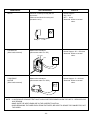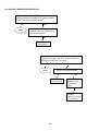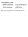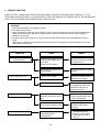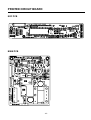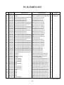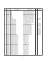
1
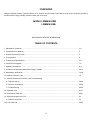
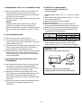
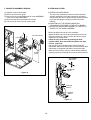
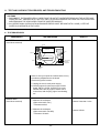
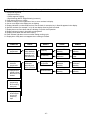
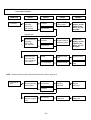
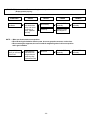
website http://www.lgservice.com
MICROWAVE OVEN
SERVICE MANUAL
MODEL : LRMM1430SW
LRMM1430SB
CAUTION
BEFORE SERVICING THE UNIT, READ THE SAFETY PRECAUTIONS IN THIS MANUAL.
CAUTION
WARNING TO SERVICE TECHNICIANS
PRECAUTIONS TO BE OBSERVED BEFORE
AND DURING SERVICING TO AVOID
POSSIBLE EXPOSURE TO EXCESSIVE
MICROWAVE ENERGY
a. Do not operate or allow the oven to be operated with the door open.
b. Make the following safety checks on all ovens to be serviced before activating the magnetron or other
microwave source, and make repairs as necessary; (1) Interlock operation, (2) proper door closing, (3)
seal and sealing surfaces (arcing, wear, and other damage), (4) damage to or loosening of hinges and
latches, (5) evidence of dropping or abuse.
c. Before turning on microwave for any service test or inspection within the microwave generating
compartments, check the magnetron, wave guide or transmission line, and cavity for proper alignment,
integrity, and connections.
d. Any defective or misadjusted components in the interlock, monitor, door seal, and microwave
generation and transmission systems shall be repaired adjusted by procedures described in this
manual before the oven is released to the owner.
e. A Microwave leakage check to verify compliance with the Federal performance standard should be
performed on each oven prior to release to the owner.
• Proper operation of the microwave ovens requires that the magnetron be assembled to the wave guide and
cavity. Never operate the magnetron unless it is properly installed.
• Be sure that the magnetron gasket is properly installed around the dome of the tube whenever installing the
magnetron.
• Routine service safety procedures should be exercised at all times.
• Untrained personnel should not attempt service without a thorough review of the test procedures and safety
information contained in this manual.
-1-
FOREWORD
Read this Manual carefully. Failure to adhere to or observe the information in this Manual may result in exposing yourself to
the Microwave Energy normally contained within the oven cavity.
MODEL LRMM1430SW
LRMM1430SB
MECHANICAL SERVICE INFORMATION
TABLE OF CONTENTS
1. Adjustment Procedures ....................................................................................................................................... 3-4
2. Precautions on Installation .................................................................................................................................. 5
3. General Precautions in Use................................................................................................................................. 5
4. Trial Operation..................................................................................................................................................... 5
5. Features and Specifications ................................................................................................................................ 5-6
6. Overall Circuit Diagram ....................................................................................................................................... 7-8
7. Operating Procedures ......................................................................................................................................... 9-11
8. Procedure for Measuring Microwave Energy Leakage........................................................................................ 12-13
9. Disassembly Instructions..................................................................................................................................... 14-18
10. Interlock Continuity Test .................................................................................................................................... 19
11. Test and Checkout Procedures, and Troubleshooting
A. Test Procedures............................................................................................................................................. 20-22
B. Checkout Procedures..................................................................................................................................... 23-25
C. Troubleshooting ............................................................................................................................................. 26-30
12. Exploded View................................................................................................................................................... 31-37
13. Replacement Parts List ..................................................................................................................................... 38-41
14. Schematic diagram of P.C.B ............................................................................................................................. 42
A. Printed circuit board ....................................................................................................................................... 43
15.P.C.B Parts List .................................................................................................................................................. 44-46
-2-
ADJUST THE LATCH AND SWITCH CLOSINGS
1. ADJUSTMENT PROCEDURES
To avoid possible exposure to microwave energy
leakage, adjust the door latches and interlock switches,
using the following procedure.
(3) Loosen the screw holding the plastic latch board as
shown.
(4) With the oven door closed tightly, move the latch board
upward toward the top of the oven and/or away from the
door latch until the gaps are less than 1/64” (0.5 mm).
ONLY AUTHORIZED SERVICE PERSONNEL
SHOULD MAKE THIS ADJUSTMENT.
Hold the latch board tightly in this position until you
check the sequence of the switches in steps 5 and 6.
The Interlock Monitor and Primary Interlock Switch acts
as the final safety switch protecting the user from
microwave energy. The terminals between “COM” and
“NC” of the Interlock Monitor must close when the door
is opened. After adjusting the Interlock Monitor Switch,
make sure that it is correctly connected. See Figures 1-a
and 1-b throughout this procedure.
TEST THE LATCH AND SWITCH SEQUENCE
(5) Open the oven door slowly. Watch the door latch, the
Primary Switch. Release Rod and Lever on the switches
to make sure they are zero to the body of the switches
in the following sequence:
CHECK THE DOOR LATCH AND SWITCH
CLOSINGS.
- Primary Interlock Switch
- Secondary Interlock Switch
- Interlock Monitor Switch
NOTE: The out case of the microwave oven is
removed.
Adjust the latch board until the switches operate in this
sequence. See Steps 3 and 4.
(1) Set the microwave oven on its side so that you can see
the latch board and the switches, as shown in
Figure 1-a.
(6) Close the oven door slowly and be sure it is tightly
closed. Watch the three switches to make sure they are
zero to the body of the switches in the following
sequence:
(2) Close the door tightly and check gaps A and B to be
sure they are no more than 1/64” (0.5 mm). See Figure
1-b for close-up view of gaps A and B (door latches).
If all gaps are less than 1/64” (0.5 mm), adjustment of
the latch board may not be necessary. Go to Steps 5
and 6 to check the sequence of the switches.
- Interlock Monitor Switch
- Primary Interlock Switch
- Secondary Interlock Switch
NOTE: To correct sequence of the Primary Interlock
Switch, Secondary Interlock Switch and the
Interlock Monitor Switch is very important.
NOTE: The Interlock Monitor Switch is an added safety
check on the Primary and Secondary Interlock
Switches. If the Primary and Secondary Interlock
Switches allow the oven to operate with the door
open, the Monitor Switch will blow the fuse.
If any gap is larger than 1/64” (0.5 mm), you will need to
adjust the latch board-U, L. Go to step 3 and follow all
steps in order.
(7) When you achieve the proper sequence of switches in
Steps 5 and 6, tighten the latch board screws at that
point.
TEST THE MICROWAVE ENERGY LEAKAGE
(8) Using a survey meter, make sure the microwave energy
is below 5 mW/cm.sq.
-3-
LATCH BOARD
SECONDARY
INTERLOCK
SWITCH
DOOR LATCH
MONITOR
INTERLOCK
SWITCH
PRIMARY
INTERLOCK
SWITCH
Figure 1-a
LATCH
(B)
0-1/64"
LATCH BOARD
(A)
0-1/64"
-4-
Figure 1-b
2. PRECAUTIONS ON INSTALLATION
4. TRIAL OPERATION
(Figure 2)
A. Plug the power supply cord into a 120 V AC, 60 Hz,
single-phase power source with a capacity of at least 20
amperes.
B. Since the unit weights about 38 lbs., be sure to place it
on a sturdy and flat surface.
C. Avoid placing the unit in a location where there is direct
heat or splashing water.
D. Place the unit as far away as possible from TV, radio,
etc. to prevent interference.
After installation, the following sequences and results
should be checked carefully.
A. Put a container filled with water (about 1 liter) into the
oven, and close the door tightly.
B. Touch the STOP/CLEAR and the COOK TIME keys. “0”
appears in the display window.
C. Set cooking time for 10 minutes by touching “1” and
then “0” three times. “10:00” appears in the display
window.
D. Touch the START key.
Make sure the cavity light comes on. The unit will begin
cooking and the display window will show the time
counting down by seconds.
E. After about 5 minutes, make sure the primary interlock
switch, the secondary interlock switch and the interlock
monitor and oven lamp switch operate properly by
opening and closing the door several times. Touch the
START key each time the door is closed.
F. Continue operating the unit. Two short and a long beep
sound signal is heard when the time is up. The unit will
shut off automatically.
G. Confirm the water is hot.
H. Finally, measure the output power according to
“POWER OUTPUT MEASUREMENT” on page 13.
CAUTION
This unit is equipped with a 3-prong plug for your
safety. If the wall outlet is a grounded 3-hole type, the
unit will be grounded automatically.
Properly Polarized and
Grounded Outlet
Three-Pronged(Grounding)
Plug
Figure 2
5. FEATURES AND SPECIFICATIONS
3. GENERAL PRECAUTIONS IN USE
A. Never operate the unit when it is empty. Operating the
oven with no load may shorten the life of the magnetron.
Whenever cooking dry foods (dried fish, bread, etc.) or a
small amount of food, be sure to put a glass of water
into the cooking compartment. The turntable tray may
become hot after operating, be careful when touching it.
B. Aluminum foil should be avoided because it will disrupt
cooking and may cause arcing. However, small pieces
may be used to cover some parts of food to slow the
cooking. Any aluminum foil used should never be closer
than 2.5 cm to any side wall of the oven.
A. The safety systems incorporated in this model are:
(1) Primary interlock switch
(2) Secondary interlock switch
(3) Interlock monitor switch
(4) Choke system
(5) Oven cavity thermostat
(Note: This thermostat located on the oven cavity will
open and stop the unit from operation only if a high
temperature is reached, such as, a fire created by
overcooking food.)
B. Any one of 10 power output levels ranging 0W to 1200W
can be selected by the touch control and electronic
computer system.
C. Cooking time can be displayed on the digital readout.
D. Three different cooking stages (Include Defrost) can be
set. The oven remembers three cooking stages and
changes from one cooking stage to another. This is
made possible with the memory function of the
microprocessor.
-5-
SPECIFICATIONS
Rated Power Consumption
Output
Frequency
Power Supply
Rated Current
Magnetron Cooling
Microwave Stirring
Rectification
Door Sealing
Safety Devices
Magnetron
Cavity Lamp
Timer
Tray
Overall Dimensions
Oven Cavity Size
Effective Capacity of Oven Cavity
Accessories
1250W maximum
1200W maximum (*IEC 60705 Rating standard)
Adjustable 0W through 1200W, 10 steps
2,450 MHz 50 MHz
120V 12V AC, 60Hz
11 Amp.
Forced Air Cooling
Turntable
Rectification Voltage Doubler Half-Wave (Inverter type)
Choke System
Thermostat:
Open at 90 ˚C 5 ˚C
Close at 75 ˚C 5 ˚C
Fuse(20A)
Primary Interlock Switch
Secondary Interlock Switch
Interlock Monitor
2M261
125V, 20W
Digital, up to 99 mm. 99 sec. (in each cooking stage)
Tempered Safety Glass
203/4”(W) x 151/4”(D) x 191/4”(H)
171/4”(W) x 9”(D) x 163/4”(H)
1.4 Cu.ft.
Owner’s Manual & Cooking Guide ,Turntable, Rotating Ring Assembly.
SWITCH CHART
SWITCH MODE
CONDITIONS
DOOR OPEN
DOOR CLOSED
PRIMARY
INTERLOCK
SWITCH
COM
NO
∞
0
NOTE: Use the above switch chart with circuit diagram on page 7.
-6-
SECONDARY
INTERLOCK
SWITCH
COM
NO
∞
0
INTERLOCK
MONITOR
SWITCH
COM
NC
0
∞
6. OVERALL CIRCUIT DIAGRAM
A. SCHEMATIC DIAGRAM
Figure 3
-7-
B. MATRIX CIRCUIT FOR TOUCH KEY BOARD
Figure 4
-8-
7. OPERATING PROCEDURES
A. CONTROL PANEL
2
3
4
5
9
6
7
8
10
1
11
12
14
13
15
16
17
18
Figure 5.
1. Display. The Display includes a clock and indicators
that tell you time of day, cooking time settings, and
cooking functions selected.
2. Sensor Touch. This pad allows you to cook most of
your favorite foods without having to select cooking
times and power levels.
3. Homemade Bakery. Homemade bakery has 3 food
categories of preset cooking time and power level.
4. Chicken Choices. Chicken Choices has 4 food
categories of preset cooking time and power level.
5. Soften. Touch this pad to soften ice cream, cream
cheese, butter or frozen juice.
6. Children’s Lunch. Children’s Lunch has 3 food
categories of preset cooking time and power level.
7. Fast Breakfast. Fast Breakfast has 3 food
categories of preset cooking time and power level.
8. Melt. Touch this pad to melt chocolate, cheese,
butter or marshmallows.
9. Auto Defrost. This pad is an accurate defrosting
method for meat, poultry, fish and bread.
10. Q-Defrost. Touch this pad to defrost foods quickly.
11. More / Less. Touch these pads to adjust cooking
time in 10 second increments.
12. Cook time. Touch this pad to set a cooking time.
13. Power. Touch this pad to set a cooking power.
14. Clock. Touch this pad to enter the time of day.
15. Kitchen Timer. Touch this pad to use your
microwave oven as a kitchen timer.
16. Number pads. Touch Number pads to enter
cooking time, Power level, quantities, or weights.
17. Stop/Clear. Touch this pad to stop the oven or
clear entries. Also used to turn Child Lock on and
off.
18. Ez-ON. You can extend cooking time in multiples
of 30 seconds by repeatedly touching this pad
during cooking.
19. Start. Touch this pad to start the oven.
-9-
19
(9) STOP/CLEAR Key
Used to stop the oven or clear all entries except
CLOCK.
B. PANEL INSTRUCTIONS (Figure 5)
The entire operation is done by simple touch control pads.
(1) Display Window
Numbers and letters explained in Figure 5 are shown in
the display window (Vacuum Fluorescent Tube).
(a) The Time in four digits (12-hour indication): 00 Hour
00 Minute.
(b) Cooking Time of Day in four digits 00 Minutes 00
Seconds.
(c) Power Control Level in three digits: P-000
(d) Each Indicator Light shows which function is set and
involved in the course of cooking by turning itself on.
Indicator Lights automatically go out upon completion
of cooking.
(10) AUTO DEFROST key (DEFROST MEAT, POULTRY,
FISH & BREAD)
Used in setting AUTO DEFROST.
(2) SENSOR COOK key
Use humidity sensor for certain food item.
(14) Ez-ON Key
It will add 30 seconds up to 3 minutes 30 seconds:
after 3 minutes 30 seconds, every touch will add 1
minute up to 99 minutes 59 seconds.
(11) Q DEFROST key
Used in setting QUICK DEFROST.
(12) KITCHEN TIMER Key
Used as a kitchen timer.
(13) POWER Key
Used to select cooking power level.
(3) HOMEMADE BAKERY key
3 food categories of preset cooking time and power
level.
(Roll/Muffin, Pancake & French Toast)
(15) START Key
Touch the START key after setting the desired cooking
times etc. Also touch the START key to resume
cooking after the cooking is temporarily stopped by
opening the door. The key will not function unless the
door is closed.
(4) CHICKEN CHOICES key
4 food categories of preset cooking time and power
level.
(Chicken Wings, Chicken Nuggets, Spicy Chicken &
Mexican Chicken )
(16) Soften
Used to soften ice cream, cream cheese, butter or
frozen juice.
(5) CHILDREN’S LUNCH key
3 food categories of preset cooking time and power
level.
(Hot Dog Buns, Frozen Pizza & Canned Pasta)
(17) Melt
Used to melt chocolate, cheese, butter or
marshmallows.
(6) FAST BREAKFAST key
3 food categories of preset cooking time and power
level.
(Oatmeal, Bacon & Scrambled Eggs)
(18) More/Less
Used to adjust cooking time in 10 second increments.
(7) CLOCK Key
Used in setting Time of Day.
(8) COOK TIME Key
The TIME key is used to set the cooking time. Touch the
TIME key and then the number keys that correspond to
the desired cooking time. The remaining time is
continuously displayed during cooking.
-10-
C. EASY USE CHART
(1) CLOCK
1. Touch STOP/CLEAR.
2. Touch CLOCK.
3. Touch numbers for correct time of day.
4. Touch CLOCK.
(6) MELT
1. Touch STOP/CLEAR.
2. Touch MELT.
Four different melt menus are provided.
3. Select Menu 1 to 4- See cooking guide.
4. Enter the amount of the Category.
(2) “HI-POWER” COOKING
1. Touch STOP/CLEAR.
2. Touch COOK TIME.
3. Touch numbers for desired cooking time.
4. Touch START.
(7) AUTO DEFROST
1. Touch STOP/CLEAR.
2. Touch AUTO DEFROST.
Three different defrosting category are provided.
(MEAT, POULTRY, FISH, BREAD)
3. Enter the weight of your food.
4. Touch START
5. At beeping, turn food over by following the
instructions in the manual.
6. After turning food over, touch START to resume
defrosting.
(3) “MULTI-STAGE” COOKING
1. Touch STOP/CLEAR.
2. Touch COOK TIME.
3. Touch numbers for cooking time.
4. Touch POWER.
5. Touch number for cooking power level.
6. Repeat steps 2-5 to set 2nd cooking stage.
7. Touch START.
(8) Q DEFROST
1. Touch STOP/CLEAR.
2. Touch Q DEFROST.
(4) CHILD LOCK
To set:
1. Touch STOP/CLEAR.
2. Hold STOP/CLEAR more than 2 seconds.
To cancel:
1. Touch STOP/CLEAR.
2. Hold STOP/CLEAR more than 2 seconds.
(9) KITCHEN TIMER
1. Touch STOP/CLEAR.
2. Touch KITCHEN TIMER.
3. Touch correct numbers for time.
4. Touch START.
(5) SOFTEN
1. Touch STOP/CLEAR.
2. Touch SOFTEN.
Four different soften menus are provided.
3. Select Menu 1 to 4- See cooking guide.
4. Enter the amount of the Category.
-11-
8. PROCEDURE FOR MEASURING MICROWAVE
ENERGY LEAKAGE
A. CAUTIONS
(1) Be sure to check a microwave emission prior to
servicing the oven if the oven is operative prior to
servicing.
(2) The service personnel should inform the manufacturer,
importer, or assembler of any certified oven unit found
to have a microwave emission level in excess of
5mW/cm.sq. and should repair any unit found to have
excessive emission levels at no cost to the owner and
should ascertain the cause of the excessive leakage.
The service personnel should instruct the owner not to
use the unit until the oven has been brought into
compliance.
(3) If the oven operates with the door open, the service
personnel should;
- Tell the user not to operate the oven
- Contact the manufacturer and CDRH (Center for
Devices and Radiological Health) immediately.
NOTE: Address on CDRH
Office of Compliance (HFZ-312)
Center for Devices and Radiological Health
1390 Piccard Drive Rockville, Maryland 20850
(4) The service personnel should check all surface and
vent openings for microwave emission testing.
(5) Check for microwave energy leakage after every
servicing. The power density of the microwave radiation
leakage emitted by the microwave oven should not
exceed 1mW/cm.sq. And always start measuring of an
unknown field to assure safety for operating personnel
from radiation leakage.
NOTE: The standard is 5mW/cm.sq. while in the
customer’s home. 1mW/cm.sq. stated here is
manufacturer’s own voluntary standard for units in
customer’s home.
B. MEASURING MICROWAVE ENERGY LEAKAGE
(1) Pour 275 15cc of 20 5 ˚C water in a beaker which is
graduated to 600 cc, and place the beaker in the center
of the oven.
(2) Set the energy leakage monitor to 2,450 MHz and use it
following the manufacturer’s recommended test
procedure to assure correct result.
(3) When measuring the leakage, always use the 2 inch
(5 cm) spacer supplied with the probe.
(4) Operate the oven at its maximum output.
(5) Measure the microwave radiation using and
electromagnetic radiation monitor by holding the probe
perpendicular to the surface being
measured. (See Figure 7)
Move probe along shaded area.
Probe scanning speed
less than 2.5 cm/sec.
Figure 7
C. MEASUREMENT WITH THE OUT CASE REMOVED
(1) When you replace the magnetron, measure for
microwave energy leakage before the outer case is
installed and after all necessary components are
replaced or adjusted. Special care should be taken in
measuring the following parts.
- Around the magnetron
- The waveguide
EQUIPMENT
Electromagnetic energy leakage monitor (NARDA
8100B, HOLADAY HI 1501)
600cc glass beaker
Glass thermometer 1000C
WARNING: AVOID CONTACTING ANY HIGH VOLTAGE
PARTS.
Figure 6
-12-
G. POWER OUTPUT MEASUREMENT
Be sure oven cavity is clean and cool .
(not used recently)
D. MEASUREMENT WITH A FULLY ASSEMBLED OVEN
(1) After all components, including the outer panels, are
fully assembled, measure for microwave energy
leakage around the door viewing window, the exhaust
opening and air inlet openings.
(2) Microwave energy leakage must not exceed the values
prescribed below.
NOTES:
Leakage with the outer panels removed - less than
5mW/cm.sq. Leakage for a fully assembled oven
(Before the latch switch (primary) is interrupted) with the
door in a slightly opened position - less than 1 mW/cm
.sq.
(1) Fill the test beaker with 59 ˚F(15 ˚C) ~ 75 ˚F(24 ˚C) 1 liter tap
water.
(2) Stir the water in the beaker with thermometer (˚F or ˚C) and
measure temperature as T1.
(3) Place the beaker on the center of turntable.
(4) Set for one (1) minute.
(5) When the heating is finished, stir the water again with
thermometer and measure the temperature of water as T2.
(6) Subtract T1 from T2, this will give you the temperature rise.
(7) The microwave power output is within specification, if the
temperature rise is as shown below:
Voltage
(VAC under load)
120V
108V
E. NOTE WHEN MEASURING
(1) Do not exceed meter full scale deflection.
(2) The test probe must be removed no faster than 1
inch/sec (2.5cm/sec) along the shaded area, otherwise
a false reading may result.
(3) The test probe must be held with the grip portion of the
handle. A false reading may result if the operator’s
hand is between the handle and the probe.
(4) When testing near a corner of the door, keep the probe
perpendicular to the surface making sure the probe
horizontally along the oven surface, this may possibly
cause probe damage.
Temperature Rise
°C
°F
13 - 15
23.4 - 27
11.5 - 13.5
20.7 - 24.3
(8) Power output will be influenced by line voltage of power
supply. Consequently, correct power output must be
measured within 120V AC 1 Volt while unit is operating.
SPECIAL TIP
• This oven used the button head screws.
F. RECORD KEEPING AND NOTIFICATION AFTER
MEASUREMENT
Button Head
(Torx style 2)
(1) After adjustment and repair of any microwave energy
interruption or microwave energy blocking device,
record the measured values for future reference. Also
enter the information on the service invoice.
(2) Should the microwave energy leakage not be more
than 1mW/cm.sq. after determining that all parts are in
good condition, functioning properly and genuine
replacement parts which are listed in this manual have
been used.
(3) At least once a year, have the electromagnetic energy
leakage monitor checked for calibration by its
manufacturer.
• When you remove the screws, using the
tamper-resistant Torx driver have a pin-in-head.
-13-
9. DISASSEMBLY INSTRUCTIONS
Remove deco front
IMPORTANT NOTES:
UNIT MUST BE DISCONNECTED FROM ELECTRICAL
OUTLET WHEN MAKING REPAIRS, RE-PLACEMENTS,
ADJUSTMENTS AND CONTINUITY CHECKS. WAIT AT
LEAST ONE MINUTE, UNTIL THE HIGH VOLTAGE
CAPACITOR IN THE HIGH VOLTAGE POWER SUPPLY
HAS FULLY DISCHARGED.
THE CAPACITOR SHOULD BE DISCHARGED BY USING
INSULATED WIRE - I.E. TEST PROBE CONNECTED TO
10K-OHM RESISTOR IN SERIES TO GROUND.
WHEN RECONNECTING THE WIRE LEADS TO
ANY PART, MAKE SURE THE WIRING CONNECTIONS
AND LEAD COLORS ARE CORRECTLY MATCHED
ACCORDING TO THE OVERALL CIRCUIT DIAGRAM.
(ESPECIALLY SWITCHES AND HIGH VOLTAGE
CIRCUIT.)
Disconnect the lead wires
A. REMOVING OUT CASE (Figure 8)
(1)
(2)
(3)
(4)
Unfasten five screws from the rear section.
Unfasten two screws from the side section.
Push the out case back about 1 inch (3cm).
Lift the case from the set.
Remove choke cap
Choke Cap
Figure 8
Remove door
B. DOOR ASSEMBLY REMOVAL (Figure 9)
(1) Remove out case.
(2) Unfasten two screws for removing deco front.
(3) Disconnect the lead wires from main board and pull that out
from the cavity.
(4) Remove the choke cap very carefully with a flat-blade screw
driver.
(5) Lift up and pull out Door assembly carefully from the cavity.
CAUTION: Be careful not to damage door seal plate with
the screw driver.
Figure 9
-14-
C.
(1)
(2)
(3)
(4)
REMOVING CONTROL CIRCUIT BOARD (Figure 10)
Remove out case.
Remove door assembly.
Unfasten two screws.
Lift up and pull out control panel assembly carefully
from the cavity.
(5) Remove door frame.
(6) Remove the F.P.C connector from the terminal socket.
(7) Unfasten two screws which tighen the circuit board.
(8) Remove control circuit board from the door panel
assembly.
D.
(1)
(2)
(3)
(4)
(5)
(6)
(7)
SEPARATE CAVITY AND BASE PLATE (Figure 11)
Remove out case.
Remove Door Assembly.
Remove five screws at the base plate.
(Front 3 EA, Back 2 EA).
Disconnect the lead wires from filter.
Disconnect all the lead wires from main board.
Disconnect the MGT high voltage lead wire and turn
table motor lead wire.
Lift up the cavity and disconnect the fan motor lead wire.
CAUTION: BE CAREFUL NOT TO DAMAGE LEAD
WIRE.
Unfasten screws
Door frame
Unfasten screws
securing
Control Panel
Remove screw
Circuit Board
Disconnect the lead wires
F.P.C.Connector
Figure 10
Figure 11
-15-
E. AIR GUIDE REMOVAL (Figure 12)
(1) Separate cavity and base plate.
(2) Unfasten the screws which hold the air guide in the
base plate.
(3) Unfasten the air guide from hook.
G.
(1)
(2)
(3)
(4)
F. POWER BOARD AND INVERTER MODULE AND
SUCTION GUIDE (Figure 12)
(1) Separate cavity and base plate.
(2) Remove air guide.
(3) Unfasten the screws.
(4) Lift up the power board, inverter module and suction
guide.
SENSOR DUCT REMOVAL (Figure 13)
Remove out case.
Unfasten the sensor duct screw.
Disconnect sensor lead wire.
Pull the sensor duct out.
Figure 13
Figure 12
-16-
H. MAGNETRON REMOVAL
I. REMOVING THE TURNTABLE MOTOR
(1) Disconnect the leadwire from the magnetron.
(2) Carefully remove the mounting screws holding the
magnetron at the waveguide.
(3) Remove the magnetron from the waveguide.
(1) Remove the turntable and turntable roller rest.
(2) Lay the unit down on its back.
(3) Remove the turntable motor cover.
The turntable base cover is easily removed by pinching
the four parts with a wire cutting.
(4) Disconnect the leadwire from the turntable motor
terminals.
(5) Remove the screw securing the turntable motor to the
oven cavity ASSEMBLY.
(6) After repairing the motor, rotate the removed turntable
motor cover.
(7) Fit the turntable motor cover’s projecting part to the
base plate slit.
NOTE:
1. When removing the magnetron, make sure its dome
does not hit any adjacent parts, or it may be damaged.
2. When replacing the magnetron, be sure to install the
magnetron gasket in the correct position and be sure that
the gasket is in good condition.
3. After replacing the magnetron, check for microwave
leakage with a survey meter around the magnetron.
Microwave energy must be below the limit of 5 mW/cm2.
(With a 275 ml. water load).
Make sure that gasket is rigidly attached to the
magnetron. To prevent microwave leakage, tighten the
mounting screws properly, making sure there is no gap
between the waveguide and the magnetron.
NOTE:
1. Remove the lead wires from the turntable motor VERY
CAREFULLY.
2. Be sure to grasp the connector, not the wires, when
removing.
Magnetron
Magnetron
Lead Wires
Magnetron
Gasket
Turntable Motor
Waveguide
Bracket
Dome
Figure 15
Waveguide
Figure 14
-17-
J. FAN MOTOR ASSEMBLY REMOVAL
K. INTERLOCK SYSTEM
(1) Separate cavity and base plate.
(2) Remove air and suction guide..
(3) Remove the two screws holding the fan motor ASSEMBLY
to the suction guide ASSEMBLY.
(4) Disconnect the wires and unfasten the screws.
(5) Pull out the Fan motor from the suction guide.
(1) INTERLOCK MECHANISM
The door lock mechanism is a device which has been
specially designed to eliminate completely microwave
activity when the door is opened during cooking and thus
to prevent the danger resulting from the microwave
leakage.
(2) MOUNTING OF THE PRIMARY/MONITOR/
SECONDARY SWITCHES TO THE LATCH BOARD
(3) INSTALLATION AND ADJUSTMENT OF THE LATCH
BOARD TO THE OVEN ASSEMBLY
• Mount the latch board to the oven assembly.
• Adjust the latch board in the arrow direction so that oven
door will not have any play in it when the door is closed.
• Tighten the mounting screw.
• Check for play in the door by pushing the door
release button. Door movement should be less than
0.5 mm. (1/64 inch)
Don't push the door release button while making this
adjustment. Make sure that the latch moves smoothly after
adjustment is completed and that the screws are tight.
Make sure the primary, monitor, and secondary switches
operate properly by following the continuity test procedure.
Fan Motor ASS’Y
Inverter
Suction
Guide
ADJUSTMENT
DIRECTION
SECONDARY
SWITCH
Figure 16
MONITOR
SWITCH
PRIMARY
SWITCH
Figure 17
-18-
10. INTERLOCK CONTINUITY TEST
WARNING : FOR CONTINUED PROTECTION AGAINST EXCESSIVE RADIATION
EMISSION, REPLACE ONLY WITH IDENTICAL REPLACEMENT PARTS.
TYPE NO. SZM-V 16-FA-63 OR VP-533A-OF OR V-5230Q FOR PRIMARY SWITCH
TYPE NO. SZM-V 16-FA-62 OR VP-532A-OF OR V-5220Q FOR MONITOR SWITCH
TYPE NO. SZM-V 16-FA-63 OR VP-533A-OF OR V-5230Q FOR SECONDARY SWITCH
A. PRIMARY INTERLOCK SWITCH TEST
B. SECONDARY INTERLOCK SWITCH TEST
When the door release button is depressed slowly with
the door closed, an audible click should be heard at
the same time or successively at intervals. When the
button is released slowly, the latches should activate
the switches with an audible click.
If the latches do not activate the switches when the
door is closed, the switches should be a adjusted in
accordance with the adjustment procedure. Disconnect
the wire lead from the primary switch. Connect the
ohmmeter leads to the common (COM) and normally
open (NO) terminal of the switch. The meter should
indicate an open circuit in the door open condition.
When the door is closed, the meter should indicate a
closed circuit.
When the primary switch operation is abnormal, make
the necessary adjustment or replace the switch only
with the same type of switch.
COMPONENTS
SWITCHES
(Lead wires removed)
Disconnect the wire lead from the secondary switch.
Connect the ohmmeter leads to the common (COM)
and normally open (NO) terminals of the switch. The
meter should indicate a open circuit in the door open
condition. When the door is closed, meter should
indicate an closed circuit. When the secondary switch
operation is abnormal, make the necessary adjustment
or replace the switch only with the same type of switch.
C. MONITOR SWITCH TEST
Disconnect the wire lead from the monitor switch.
Connect the ohmmeter leads to the common (COM)
and normally closed (NC) terminals of the switch. The
meter should indicate closed circuit in the door open
condition. When the door is closed, meter should
indicate an open circuit. When the monitor switch
operation is abnormal, replace with the same type of
switch.
NOTE: After repairing the door or the interlock system,
it is necessary to do this continuity test before
operating the oven.
TEST PROCEDURE
Check for continuity of the
switch with an Ohm-meter
Primary
Switch
Monitor
Switch
Secondary
Switch
RESULTS
Door
open
NO
COM
NC
COM
NO
COM
NOTE : After checking for the continuity of switches, make sure that they are
connected correctly.
-19-
Door
closed
11. TEST AND CHECKOUT PROCEDURES, AND TROUBLESHOOTING
CAUTIONS
1. DISCONNECT THE POWER SUPPLY CORD FROM THE OUTLET WHENEVER REMOVING THE OUTER CASE
FROM THE UNIT. PROCEED WITH THE TEST ONLY AFTER DISCHARGING THE HIGH VOLTAGE CAPACITOR
AND REMOVING THE LEAD WIRES FROM THE INVERTER MODULE.
2. ALL OPERATIONAL CHECKS WITH MICROWAVE ENERGY MUST BE DONE WITH A LOAD (1 LITER OF
WATER IN CONTAINER) IN THE OVEN.
A. TEST PROCEDURES
COMPONENTS
TEST PROCEDURE
RESULTS
INVERTER
(Lead wires removed)
CN702
Heat Sink
E701
120V AC
CN701
High Voltage
Output to
Magnetron
CN703
Control Signal
In/Out
Note: Do not try to repair the inverter board, nor try
to make any adjustments to the board.
Check wiring to the inverter:
1. Unplug the oven’s main power supply.
2. Visually inspect 4 connectors on the inverter
board: CN701, CN702, CN703, E701 to see
whether there are any signs of failure due to
loose wires, bad crimping, sign of overheating,
etc.
MAGNETRON
(Lead wires removed)
1. Measure the resistance.
(Ohm-meter scale: Rx1)
• Filament terminal
2. Measure the resistance.
(Ohm-meter scale: Rx1000)
• Filament to chassis
-20-
Normal: Less than 1 ohm
Normal: Infinite
COMPONENTS
TEST PROCEDURE
RESULTS
Antenna
Gasket
Chassis
Filament
NOTE: When testing the magnetron, be sure to install the magnetron gasket in
the correct position and be sure that the gasket is in good condition.
SENSOR
1. Disconnect sensor connector from micom
computer board.
2. Measure resistance terminal to terminal
(Select the ohm scale on the meter)
Normal: Approximately
BK-RD: 5.2 Kohms
RD-WH: 2.1 Kohms
BK-WH: 2.1 Kohms
Abnormal:
Infinite or several
NOTE: MAKE SURE THE LEAD WIRES ARE
IN THE CORRECT POSITION.
WHEN REMOVING THE LEAD
WIRES FROM THE PARTS, BE
SURE TO GRASP THE
CONNECTOR, NOT THE WIRES.
-21-
*Sensor cooking condition
1. Oven should be plugged in at
least 5 minutes before sensor
cooking.
2. Room temperature should not
exceed 95˚F.
3. Be sure the exterior of the
cooking container and the
interior of the oven are dry.
4. The oven will not generate
microwave energy for the first
28 seconds of the sensor
cooking cycle.
COMPONENTS
RELAY
TEST PROCEDURE
Check for continuity of relay with an
ohm-meter.
(Remove lead wires from relay and
operate the unit.)
RESULTS
Normal: Approx.
ON: 0 ohm
OFF: ∞ ohms
Abnormal: Infinite or several
ohms.
Relay 2
FAN MOTOR
(Wire leads removed)
Measure the resistance.
(Ohm-meter scale: R x 100)
A(RD)
B(BK)
Normal: Approx. 50 ~ 150 ohms
Abnormal: Infinite or several
ohms.
C(WH)
TURNTABLE
MOTOR
(Wire leads removed)
Measure the resistance.
(Ohm-meter scale: R x 1000)
Normal: Approx. 2 ~ 4K ohms
Abnormal: Infinite or several
ohms.
NOTE : • A MICROWAVE LEAKAGE TEST MUST ALWAYS BE PERFORMED WHEN THE UNIT IS SERVICED FOR
ANY REASON.
• MAKE SURE THE WIRE LEADS ARE IN THE CORRECT POSITION.
• WHEN REMOVING THE WIRE LEADS FROM THE PARTS, BE SURE TO GRASP THE CONNECTOR, NOT
THE WIRES.
-22-
B. CHECKOUT PROCEDURES
(1) CHECKOUT PROCEDURES FOR FUSE BLOWING
CAUTION: REPLACE BLOWN FUSE WITH 20 AMPERE FUSE.
PROBLEMS
Fuse blows immediately after
the door is closed.
Fuse blows immediately after
the door is opened.
Fuse blows when the door is closed and START key
is touched.
CAUSES
Improper operation of the primary interlock,
secondary interlock switches and/or the interlock
monitor switch.
Malfunction of the Inverter, the magnetron,
the fan motor or the circuit board.
NOTES:
- If the fuse is blown by an improper switch operation, replace the defective switches and the fuse at the same time.
After replacing the defective switches with new ones, make sure that they are correctly connected.
- Check for microwave energy leakage according to “1. ADJUSTMENT PROCEDURES” on page 3, when the primary
interlock, secondary interlock switches and/or the interlock monitor switches are adjusted or replaced.
-23-
(2) CHECKOUT PROCEDURES FOR RELAY
- PROBLEM (A) FAN motor and oven lamp turn on without touching
START key when the door is closed.
NO
GOOD
YES
Remove the mate connector of I/O
CON from the circuit board does
the unit still operate?
NO
Replace the
circuit board
- PROBLEM (B) FAN motor and oven lamp turn on When the door is
closed and START key is touched.
NO
YES
Check the interlock switches
GOOD
NO
Replace the
micro switches.
YES
Defective
RELAY or poor
connection of
relay
Replace
RELAY or correct
the connection.
-24-
(3) CHECKOUT PROCEDURES FOR CIRCUIT BOARD
The following symptoms indicate a defective circuit
board.
(1) Check the input current. If the input current is more
than 20A, check the magnetron and wiring. If the
input current is less than 0.5 A, there is no input to
the inverter.
(2) The start function fails to operate but the interlock
switches, the door sensing and the relay check
good.
(3) The unit with a normal relay continuously operates.
(4) The buzzer does not sound or continues to sound.
(5) Some segments of one or more digits do not light
up, or they continue to light up, or segments light
when they should not.
(6) Wrong figures appear.
(7) The figures of all digits flicker.
(8) Some of the indicators do no light up.
(9) The clock does not keep time properly.
NOTE: A MICROWAVE ENERGY LEAKAGE TEST MUST ALWAYS BE PERFORMED WHEN THE UNIT IS
SERVICED FOR ANY REASON.
-25-
C. TROUBLE SHOOTING
WHEN YOU GET A COMPLAINT FROM YOUR CUSTOMER, EVALUATE THE COMPLAINT CAREFULLY. IF THE
FOLLOWING SYMPTOMS APPLY, PLEASE INSTRUCT THE CUSTOMER IN THE PROPER USE OF THE MICROWAVE
OVEN. THIS CAN ELIMINATE AN UNNECESSARY SERVICE CALL.
CAUTIONS
1. Check grounding before checking for trouble.
2. Be careful of the Inverter.
3. When checking the continuity of the switches or of the inverter, disconnect one lead wire from these parts
and then check continuity with the AC plug removed. To do otherwise may result in a false reading or
damage to your meter.
4. Do not touch any part of the circuit on the PCB since static electric discharge may damage this control
panel.
Always touch yourself to ground while working on this panel to discharge any static charge built up in your
body. (Micom model only)
CONDITION
CAUSE
REMEDY
Microwave oven
does not work.
Inserting many plugs into one
outlet and using them at the
same time.
(blown fuse or breaker)
Avoid using other electrical
appliances when you use the
microwave oven.
Microwave oven plug is not
inserted tightly.
Insert microwave oven plug
securely.
Low AC input voltage.
Use the microwave oven at
adequate line voltage.
Food temperature is too low.
This may not be a defect.
It is possible that the food
should be cooked for a
longer time period.
Using metallic ware and
allowing it to touch the oven
wall.
Do not use metallic ware for
cooking except where noted
in the cooking guide.
Ceramic ware trimmed in
gold or silver powder is used.
Do not use any type of
cookware with metallic
trimming.
Inconsistent intensity of
microwave by their
characteristics.
1. Use plastic wrap or lid.
2. Stir once or twice while
cooking soup, cocoa or
milk, etc.
Output power is too low.
Sparks occur.
Uneven cooking.
-26-
(TROUBLE 1) The following visual conditions indicate a probable defective control circuit.
1. Incomplete segments.
• Segment missing.
• Partial segment missing.
• Digit flickering (NOTE: Slight flickering is normal.)
2. Colon does not turn on or blink.
3. A distinct change in the brightness of one or more numbers in display.
4. One or more digits in the display are not lighting.
5. Display indicates a number different from one touched, for example, key in 5 and 3 appears in the display.
6. Specific numbers (for example 7 or 9) will not display when key pad is touched.
7. Display does not count down with time blinking or up with clock operation.
8. Display obviously jumps in time while counting down.
9. Display counts down too fast while cooking.
10. Each indicator light does not turn on after setting cooking cycle.
11. Display time of day does not reappear when cooking is finished.
CONDITION
CHECK
1. No input can be
programmed.
Check the connection between
membrane key
assembly and
PCB assembly.
Continuity
Defective PCB
assembly.
Replace PCB
assembly.
No continuity
Loose
connection.
Connect them
tightly.
Replace key
membrane
assembly and
check operation.
Everything works
as specified.
Defective key
membrane
assembly.
Replace key
membrane
assembly.
Defective PCB
assembly.
Replace PCB
assembly.
2. Some inputs
cannot be
programmed.
3. Display shows a
number or figure
different from one
touched.
RESULT
Still have trouble.
4. Random
programming
when touching
other pads.
5. Display is fixed
at some figure
and can not
accept any
input.
-27-
CAUSE
REMEDY
(TROUBLE 2) Oven does not operate at all, Display window does not display any figures,
and no input is accepted.
CONDITION
1. Fuse blows.
CHECK
Check continuity
of monitor
switch (with
door closed).
RESULT
Continuity.
CAUSE
REMEDY
Malfunction of the
monitor switch.
Replace fuse,
primary, monitor
switches, and
RELAY of P.C.B
Assembly.
Shorted contact at
the primary switch.
Replace fuse,
primary, monitor
switches, and
RELAY of P.C.B
Assembly.
No continuity.
Replace fuse
Check continuity
of primary
switch (with
door opened).
Continuity.
Disconnect one
side of the lead
wires connected
from Inverter.
Normal.
Defective control
PCB.
Replace Inverter.
Fuse blows again
Defective Inverter.
Replace control
PCB.
No continuity.
NOTE : All these switches must be replaced at the same time. Refer to page 18, 19
2. Fuse does not
blow.
Check continuity
of thermostat.
No continuity.
Defective
thermostat.
Replace
thermostat.
Defective power
supply cord.
Replace power
supply cord.
Continuity.
Check continuity
of power supply
cord.
No continuity.
-28-
(TROUBLE 3) Display shows all figures set, but oven does not start cooking while desired
program times are set and START pad is touched.
CONDITION
CHECK
1. Setting time
does not count
down when
touching START
pad.
Check continuity
of secondary
switch (with
door closed).
2. Fan motor or
oven lamp do
not turn on.
RESULT
No continuity.
CAUSE
REMEDY
Defective
secondary switch.
Replace
secondary switch.
Continuity.
Check the connection between
CN1 connector
and PCB
assembly.
Continuity
Defective Power
PCB assembly.
Replace Power
PCB assembly.
No continuity
Loose connection.
Connect them
tightly.
Check fan motor.
Abnormal
Defective fan motor.
Replace fan motor.
Check oven lamp.
Abnormal
Defective oven lamp.
Replace oven lamp.
Normal
(TROUBLE 4) Oven seems to be operating but little heat is produced in oven load.
CONDITION
Output is low
CHECK
Check the
power source
voltage.
RESULT
CAUSE
REMEDY
Lower than 90% of
rating voltage.
Decrease in power
source voltage
with load.
Suggest customer
contact local
electric power
utility co. or
qualified
electrician.
Defective
Magnetron.
Replace
Magnetron.
Normal
NOTE : Simple test of power output-conducted by heating one liter water for one min. if available.
Minimum 8.5°C temperature rise is normal condition.
-29-
(TROUBLE 5) No microwave oscillation even though oven lamp and fan motor run.
(Display operates properly)
CONDITION
No microwave
oscillation.
CHECK
Disconnect the
wire leads from
relay and check
continuity of
relay. (Operate
the unit)
RESULT
CAUSE
No continuity.
Defective PCB
assembly.
Continuity.
Replace Inverter
and Magnetron.
REMEDY
Replace PCB
assembly.
NOTE : • Make sure the wire leads correct position.
• When Removing the lead wires from the parts, be sure to grasp the connector, not the wires.
• When removing the magnetron, be sure to install the magnetron gasket in the correct position
and in good condition.
Output is full power
when you set lower
power level.
Disconnect the
lead wires from
relay and check
continuity relay .
(Operate the unit)
Abnormal.
-30-
Defective PCB
assembly.
Replace PCB
assembly.
EXPLODED VIEW
INTRODUCTION
-31-
DOOR PARTS
13552A
13536A
15006A
13581A
13213A
WTP002
14026A
WTP002
13551A
14970A
268711
23506A
-32-
13806A
CONTROLLER PARTS
WTP002
13551A
268711
23506A
-33-
OVEN CAVITY PARTS
WSZ185
33112U
WTT022 :Model LRMM 1430SW
W107 :Model LRMM 1430SB
33390G
33052A
35889A
36549S
WTP013
13806F
647781
-34-
LATCH BOARD PARTS
43501A
WSZ085
466001
43500A
466003
466001
-35-
OVEN INTERIOR PARTS
WTT021
WTT028
56501A
54974T
56930V
56912B
56324A
WSZ002
43500A
-36-
BASE PLATE PARTS
56411A
WTT028
WTT028
268712
56851H
WTT028
568771
WTT021
WSZ002
56549F
WTT034
WTT028
35264A
568711
568772
54974S
55900A
50FZZA
55238A
56201A
54980A
63302A
65006B
-37-
43501A
REPLACEMENT PARTS LIST
FOR MODEL : LRMM1430SB
LOC.
NO.
*01
*02
*10
13213A
13536A
13552A
13581A
13806F
14026A
14970A
15006A
23506A
268711
268712
33052A
33112U
33390G
35264A
35889A
36549S
43500A
43501A
466001
466003
50FZZA
54974S
54974T
54980A
55238A
55900A
56201A
56324A
56411A
56501A
56549F
56851H
568711
568771
568772
56912B
56930V
63302A
647781
65006B
W107
WSZ002
WSZ085
WSZ185
PART NO.
3828W5A3194
3828W5S3066
3890W3W376B
3213W0A008B
3536W1A002A
3552W0A009A
3581W0A077B
3806W1A062A
4026W1A025A
4970WRA001C
5006W1A005A
3506W1A443B
6871W1S144C
6871W1S145A
3052W3A015A
3112W0U048C
3390W1A017A
4974W0A006A
5889W1A003A
6549W1S015A
3500W0A002A
3501W1A030A
6600W1K004C
6600W1K004B
3B74133K
4974W1A014A
4810W1A079A
4B73792B
4974W1A013A
2B72125A
6201W1A008F
6324W1A002B
6411W1A027A
6501W1A006E
6549W1F008B
6850W1A001B
6871W1S019A
6877W1A434A
6631W3A003Q
6912W3B002Q
6930W1A001J
3302W0A041A
4778W1A002A
5006W3A016B
1TTL0402416
1SBF0402418
4B70188C
1SZZW2A002A
DESCRIPTION
MANUAL,OWNERS
MANUAL,SERVICE
BOX,WHITE
DOOR FRAME ASSEMBLY
SEAL TAPE
CHOKE COVER
DOOR ASSEMBLY
DECO,FRONT
LATCH
SPRING
CAP,CHOKE COVER
KEY MEMBRANE
PWB(PCB) ASSEMBLY,SUB
PWB(PCB) ASSEMBLY,SUB
CANOPY,RESIN
OUT CASE,U-BENDING
TRAY,GLASS
GUIDE,AIR
ROTATING RING ASSEMBLY
MOTOR(CIRC),SYNCHRONOUS
BOARD,LATCH
BOARD ASSEMBLY,LATCH
SWITCH,MICRO
SWITCH,MICRO
FUSE,DRAWING
GUIDE,SUCTION
BRACKET,SENSOR
SUPPORTER
GUIDE,AIR
FAN
FILTER ASSEMBLY(CIRC)
MAGNETRON
POWER CORD ASSEMBLY
SENSOR ASSEMBLY
MOTOR(CIRC),FAN
CABLE,HIGH VOLTAGE
PWB(PCB) ASSEMBLY,SUB
HARNESS
HARNESS
LAMP,DRAWING
THERMOSTAT
BASE PLATE
LEG
CAP,BASE PLATE
SCREW TAPPING, TRUSS HEAD
SCREW TAP TITE(S),BINDING HEAD
SCREW,DRAWING
SCREW,DRAWING
SVC
R
R
R
R
S
R
R
R
R
R
R
R
R
R
R
R
R
R
R
R
R
R
R
R
R
R
R
R
R
S
R
R
R
R
R
R
R
R
R
R
R
R
R
R
R
R
R
R
ALTER
6549W1S011A
3B73362F
3B73361E
3B74133H
6411W1A027B
6549W1F005B
6912W3B002G
6930W1A003A
R,S: SERVICE PARTS
-38-
LOC.
NO.
WTP002
WTP013
WTT021
WTT028
WTT034
PART NO.
1TPL0302018
1TPL0402418
1TTL0402418
1TTL0402818
1TTL0403418
DESCRIPTION
SCREW TAPPING,PAN HEAD
SCREW TAPPING,PAN HEAD
SCREW TAPPING,TRUSS HEAD
SCREW TAPPING,TRUSS HEAD
SCREW TAPPING,TRUSS HEAD
SVC
ALTER
R
R
R
R
R
R,S: SERVICE PARTS
-39-
FOR MODEL : LRMM1430SW
LOC.
NO.
*01
*02
*10
13213A
13352A
13536A
13552A
13581A
13720D
13806F
14026A
14970A
15006A
23506A
268711
268712
33052A
33112U
33390G
35264A
35889A
36549S
43500A
43501A
466001
466003
50FZZA
54974S
54974T
54980A
55238A
55900A
56201A
56324A
56411A
56501A
56549F
56851H
568711
568771
568772
56912B
56930V
63302A
647781
65006B
WSZ002
WSZ085
PART NO.
3828W5A3340
3828W5S3192
3890W3W377A
3213W0A008C
3352W1A144A
3536W1A002A
3552W0A009A
3581W0A077E
3720W0D308A
3806W1A062B
4026W1A025A
4970WRA001C
5006W1A005A
3506W1A443C
6871W1S144C
6871W1S145A
3052W3A015A
3112W0U048D
3390W1A017A
4974W0A006A
5889W1A003A
6549W1S015A
3500W0A002A
3501W1A030A
6600W1K004C
6600W1K004B
3B74133K
4974W1A014A
4810W1A079A
4B73792B
4974W1A013A
2B72125A
6201W1A010C
6324W1A005A
6411W2A002R
6501W1A006E
6549W1F008B
6850W1A001F
6871W1S019A
6877W1A481A
6631W3A003Q
6912W3B002Q
6930W1A001J
3302W0A041A
4778W1A002A
5006W3A016B
1SBF0402418
4B70188C
DESCRIPTION
MANUAL,OWNERS
MANUAL,SERVICE
BOX,WHITE
DOOR FRAME ASSEMBLY
FRONT SCREEN
SEAL TAPE
CHOKE COVER
DOOR ASSEMBLY
PANEL,DOOR
DECO,FRONT
LATCH
SPRING
CAP,CHOKE COVER
KEY MEMBRANE
PWB(PCB) ASSEMBLY,SUB
PWB(PCB) ASSEMBLY,SUB
CANOPY,RESIN
OUT CASE,U-BENDING
TRAY,GLASS
GUIDE,AIR
ROTATING RING ASSEMBLY
MOTOR(CIRC),SYNCHRONOUS
BOARD,LATCH
BOARD ASSEMBLY,LATCH
SWITCH,MICRO
SWITCH,MICRO
FUSE,DRAWING
GUIDE,SUCTION
BRACKET,SENSOR
SUPPORTER
GUIDE,AIR
FAN
FILTER ASSEMBLY(CIRC)
MAGNETRON
POWER CORD ASSEMBLY
SENSOR ASSEMBLY
MOTOR(CIRC),FAN
CABLE,HIGH VOLTAGE
PWB(PCB) ASSEMBLY,SUB
HARNESS
HARNESS
LAMP,DRAWING
THERMOSTAT
BASE PLATE
LEG
CAP,BASE PLATE
SCREW TAP TITE(S),BINDING HEAD
SCREW,DRAWING
SVC
R
R
R
R
S
S
R
R
R
R
R
R
R
R
R
R
R
R
R
R
R
R
R
R
R
R
R
R
R
R
R
S
R
R
B
R
R
R
R
R
R
R
R
R
R
R
R
R
ALTER
6549W1S011A
3B73362F
3B73361E
3B74133H
6549W1F005B
6912W3B002G
6930W1A003A
R,S: SERVICE PARTS
-40-
LOC.
NO.
WTP002
WTP013
WTT021
WTT022
WTT028
WTT034
PART NO.
1TPL0302018
1TPL0402418
1TTL0402418
1TTL0402422
1TTL0402818
1TTL0403418
DESCRIPTION
SCREW TAPPING,PAN HEAD
SCREW TAPPING,PAN HEAD
SCREW TAPPING,TRUSS HEAD
SCREW TAPPING,TRUSS HEAD
SCREW TAPPING,TRUSS HEAD
SCREW TAPPING,TRUSS HEAD
SVC
ALTER
R
R
R
R
R
R
R,S: SERVICE PARTS
-41-
SCHEMATIC DIAGRAM OF P.C.B
-42-
PRINTED CIRCUIT BOARD
KEY PCB
MAIN PCB
-43-
P.C.B. PARTS LIST
LOC.
NO.
AR1
BZ1
C01
C02
C03
C04
C05
C06
C08
C09
C10
C11
C14
C15
C16
C20
C21
C25
C45
C50
C60
C61
C62
C63
C65
C80
C81
C82
C83
C84
CN5
CN6
CR1
CU4
D01
D02
D03
D05
D10
D11
D12
D15
D20
D25
D26
D30
D32
D38
D60
PART NO.
0RZ1503G610
6908W3YA01C
0CK1040K948
0CE2276K618
0CE4771J618
0CE4756K638
0CK2230K948
0CK1040K948
0CE1076D638
0CK2230K948
0CK1040K948
0CE1076K638
0CK1040K948
0CE1076K638
0CE1066K638
0CK2230K948
0CK2230K948
0CK2230K948
0CK1020K518
0CE4766K638
0CK2230K948
0CK2230K948
0CK2230K948
0CK2230K948
0CK2230K948
0CK2210K518
0CK2210K518
0CK2210K518
0CK2210K518
0CK2210K518
6877W1A437A
6877W1A437A
6212W5M002A
4850W4C001A
0DD400209AA
0DD400209AA
0DD400209AA
0DD414809AB
0DD400209AA
0DD414809AB
0DD414809AA
0DD400209AA
0DD414809AA
0DD414809AB
0DD414809AB
0DD414809AB
0DD414809AB
0DD414809AB
0DD414809AA
DESCRIPTION
RESISTOR,DRAWING
BUZZER
CAPACITOR,FIXED CERAMIC(HIGH DIELECTRIC)
CAPACITOR,FIXED ELECTROLYTIC
CAPACITOR,FIXED ELECTROLYTIC
CAPACITOR,FIXED ELECTROLYTIC
CAPACITOR,FIXED CERAMIC(HIGH DIELECTRIC)
CAPACITOR,FIXED CERAMIC(HIGH DIELECTRIC)
CAPACITOR,FIXED ELECTROLYTIC
CAPACITOR,FIXED CERAMIC(HIGH DIELECTRIC)
CAPACITOR,FIXED CERAMIC(HIGH DIELECTRIC)
CAPACITOR,FIXED ELECTROLYTIC
CAPACITOR,FIXED CERAMIC(HIGH DIELECTRIC)
CAPACITOR,FIXED ELECTROLYTIC
CAPACITOR,FIXED ELECTROLYTIC
CAPACITOR,FIXED CERAMIC(HIGH DIELECTRIC)
CAPACITOR,FIXED CERAMIC(HIGH DIELECTRIC)
CAPACITOR,FIXED CERAMIC(HIGH DIELECTRIC)
CAPACITOR,FIXED CERAMIC(HIGH DIELECTRIC)
CAPACITOR,FIXED ELECTROLYTIC
CAPACITOR,FIXED CERAMIC(HIGH DIELECTRIC)
CAPACITOR,FIXED CERAMIC(HIGH DIELECTRIC)
CAPACITOR,FIXED CERAMIC(HIGH DIELECTRIC)
CAPACITOR,FIXED CERAMIC(HIGH DIELECTRIC)
CAPACITOR,FIXED CERAMIC(HIGH DIELECTRIC)
CAPACITOR,FIXED CERAMIC(HIGH DIELECTRIC)
CAPACITOR,FIXED CERAMIC(HIGH DIELECTRIC)
CAPACITOR,FIXED CERAMIC(HIGH DIELECTRIC)
CAPACITOR,FIXED CERAMIC(HIGH DIELECTRIC)
CAPACITOR,FIXED CERAMIC(HIGH DIELECTRIC)
HARNESS
HARNESS
RESONATOR,CERAMIC
CUSHION
DIODE,RECTIFIERS
DIODE,RECTIFIERS
DIODE,RECTIFIERS
DIODE
DIODE,RECTIFIERS
DIODE
DIODE,SWITCHING
DIODE,RECTIFIERS
DIODE,SWITCHING
DIODE
DIODE
DIODE
DIODE
DIODE
DIODE,SWITCHING
SPECIFICATION
150KOHM 1/4W 5% 3216 BULK 8 PIN
TFM-57 CW NINGBO EAST PIEZO 2048HZ 70D
0.1UF D 50V 80%,-20% F(Y5V) TA26
220UF SMS,SG 50V 20% FL TP 5
470UF SM,SA 35V 20% FL TP 5
4.7UF SMS,SG 50V 20% FM5 TP 5
22NF D 50V 80%,-20% F(Y5V) TA26
0.1UF D 50V 80%,-20% F(Y5V) TA26
100UF SMS,SG 10V 20% FM5 TP 5
22NF D 50V 80%,-20% F(Y5V) TA26
0.1UF D 50V 80%,-20% F(Y5V) TA26
100UF SMS,SG 50V 20% FM5 TP 5
0.1UF D 50V 80%,-20% F(Y5V) TA26
100UF SMS,SG 50V 20% FM5 TP 5
10UF SMS,SG(HR) 50V 20% FM5 TP 5
22NF D 50V 80%,-20% F(Y5V) TA26
22NF D 50V 80%,-20% F(Y5V) TA26
22NF D 50V 80%,-20% F(Y5V) TA26
10KPF D 50V K B TA26
47UF SMS,SG 50V 20% FM5 TP 5
22NF D 50V 80%,-20% F(Y5V) TA26
22NF D 50V 80%,-20% F(Y5V) TA26
22NF D 50V 80%,-20% F(Y5V) TA26
22NF D 50V 80%,-20% F(Y5V) TA26
22NF D 50V 80%,-20% F(Y5V) TA26
220PF D 50V 10% B(Y5P) TA26
220PF D 50V 10% B(Y5P) TA26
220PF D 50V 10% B(Y5P) TA26
220PF D 50V 10% B(Y5P) TA26
220PF D 50V 10% B(Y5P) TA26
CONTROLLER LGECW SEARS MS-1442KCSV
CONTROLLER LGECW SEARS MS-1442KCSV
CSTS0400 MURATA 4MHZ +/-0.5% TP 15PF
3.5T 15W 40L RUBBER BLACK
1N4002 PYUNG CHANG TP26 DO41 100V 1A 30
1N4002 PYUNG CHANG TP26 DO41 100V 1A 30
1N4002 PYUNG CHANG TP26 DO41 100V 1A 30
1N4148M PYUNG CHANG TP26 DO34 60V 0.5A 0
1N4002 PYUNG CHANG TP26 DO41 100V 1A 30
1N4148M PYUNG CHANG TP26 DO34 60V 0.5A 0
1N4148 ROHM TP26 DO35 100V 450MA 2A 3NS
1N4002 PYUNG CHANG TP26 DO41 100V 1A 30
1N4148 ROHM TP26 DO35 100V 450MA 2A 3NS
1N4148M PYUNG CHANG TP26 DO34 60V 0.5A 0
1N4148M PYUNG CHANG TP26 DO34 60V 0.5A 0
1N4148M PYUNG CHANG TP26 DO34 60V 0.5A 0
1N4148M PYUNG CHANG TP26 DO34 60V 0.5A 0
1N4148M PYUNG CHANG TP26 DO34 60V 0.5A 0
1N4148 ROHM TP26 DO35 100V 450MA 2A 3NS
SVC
R
R
R
R
R
R
R
R
R
R
R
R
R
R
R
R
R
R
R
R
R
R
R
R
R
R
R
R
R
R
R
R
R
R
R
R
R
R
R
R
R
R
R
R
R
R
R
R
R
ALTER
6908W3YA01A
R: SERVICE PARTS
-44-
LOC.
NO.
D61
D90
D91
D92
D93
D94
D95
D96
DP1
IC1
PT1
Q01
Q02
Q20
Q30
Q36
Q37
Q38
Q50
Q51
Q71
Q72
Q73
Q74
Q75
Q98
Q99
R01
R02
R03
R04
R05
R06
R07
R10
R100
R101
R103
R104
R11
R110
R12
R13
R20
R21
R22
R23
R25
R26
PART NO.
0DD414809AA
0DD414809AB
0DD414809AB
0DD414809AB
0DD414809AB
0DD414809AB
0DD414809AB
0DD414809AB
6302W5A023A
0ISS791500A
6010W2P043P
0TR101509AB
0TR101509AB
0TR181509AB
0TR105009AD
0TR107009AE
0TR181509AB
0TR107009AE
0TR107009AE
0TR107009AD
0TR107009AE
0TR107009AE
0TR107009AE
0TR107009AE
0TR107009AE
0TR107009AE
0TR107009AE
0RD1001F608
0RD1501F608
0RD4701F608
0RD1001F608
0RN5601F408
0RN2702F408
0RD1001G608
0RD1000F608
0RD4702F608
0RD1002F608
0RD4702F608
0RD4702F608
0RD0102G608
0RD4701F608
0RD0102G608
0RD1003F608
0RD1002G608
0RD1001F608
0RD2202F608
0RD1002F608
0RD3901G608
0RD1001F608
DESCRIPTION
DIODE,SWITCHING
DIODE
DIODE
DIODE
DIODE
DIODE
DIODE
DIODE
DIGITRON
IC,LINEAR
TRANSFORMER,POWER
TRANSISTOR,BIPOLARS
TRANSISTOR,BIPOLARS
TRANSISTOR,BIPOLARS
TRANSISTOR,BIPOLARS
TRANSISTOR,BIPOLARS
TRANSISTOR,BIPOLARS
TRANSISTOR,BIPOLARS
TRANSISTOR,BIPOLARS
TRANSISTOR,BIPOLARS
TRANSISTOR,BIPOLARS
TRANSISTOR,BIPOLARS
TRANSISTOR,BIPOLARS
TRANSISTOR,BIPOLARS
TRANSISTOR,BIPOLARS
TRANSISTOR,BIPOLARS
TRANSISTOR,BIPOLARS
RESISTOR,FIXED CARBON FILM
RESISTOR,FIXED CARBON FILM
RESISTOR,FIXED CARBON FILM
RESISTOR,FIXED CARBON FILM
RESISTOR,FIXED METAL FILM
RESISTOR,FIXED METAL FILM
RESISTOR,FIXED CARBON FILM
RESISTOR,FIXED CARBON FILM
RESISTOR,FIXED CARBON FILM
RESISTOR,FIXED CARBON FILM
RESISTOR,FIXED CARBON FILM
RESISTOR,FIXED CARBON FILM
RESISTOR,FIXED CARBON FILM
RESISTOR,FIXED CARBON FILM
RESISTOR,FIXED CARBON FILM
RESISTOR,FIXED CARBON FILM
RESISTOR,FIXED CARBON FILM
RESISTOR,FIXED CARBON FILM
RESISTOR,FIXED CARBON FILM
RESISTOR,FIXED CARBON FILM
RESISTOR,FIXED CARBON FILM
RESISTOR,FIXED CARBON FILM
SPECIFICATION
1N4148 ROHM TP26 DO35 100V 450MA 2A 3NS
1N4148M PYUNG CHANG TP26 DO34 60V 0.5A 0
1N4148M PYUNG CHANG TP26 DO34 60V 0.5A 0
1N4148M PYUNG CHANG TP26 DO34 60V 0.5A 0
1N4148M PYUNG CHANG TP26 DO34 60V 0.5A 0
1N4148M PYUNG CHANG TP26 DO34 60V 0.5A 0
1N4148M PYUNG CHANG TP26 DO34 60V 0.5A 0
1N4148M PYUNG CHANG TP26 DO34 60V 0.5A 0
10-MT-127GN 9 MS-2142KSZ SEARS,2-LINE 3KA7915 FAIRCHILD 3PIN TO220 BK REGULARTO
120V 60HZ DC 12V / AC 3.4V LGETA LEADER(
A1015(KTA12660) KEC TP TO92 50V 150MA
A1015(KTA12660) KEC TP TO92 50V 150MA
KTC1815-Y(KTC3198Y) KEC TP TO92 50V 150M
KRA105M KEC TP TO92 50V 100MA
KRA107M KEC TP TO92M 50V 100MA
KTC1815-Y(KTC3198Y) KEC TP TO92 50V 150M
KRA107M KEC TP TO92M 50V 100MA
KRA107M KEC TP TO92M 50V 100MA
KRC 107M KEC TP TO92M 50V 100MA
KRA107M KEC TP TO92M 50V 100MA
KRA107M KEC TP TO92M 50V 100MA
KRA107M KEC TP TO92M 50V 100MA
KRA107M KEC TP TO92M 50V 100MA
KRA107M KEC TP TO92M 50V 100MA
KRA107M KEC TP TO92M 50V 100MA
KRA107M KEC TP TO92M 50V 100MA
1K OHM 1/6 W 5% TA26
1.5K OHM 1/6 W 5% TA26
4.7K OHM 1/6 W 5% TA26
1K OHM 1/6 W 5% TA26
5.6K OHM 1/6 W 1% TA26
27K OHM 1/6 W 1% A26
1K OHM 1/4 W 5% TA26
100 OHM 1/6 W 5% TA26
47K OHM 1/6 W 5% TA26
10K OHM 1/6 W 5% TA26
47K OHM 1/6 W 5% TA26
47K OHM 1/6 W 5% TA26
10 OHM 1/4 W 5% TA26
4.7K OHM 1/6 W 5% TA26
10 OHM 1/4 W 5% TA26
100K OHM 1/6 W 5% TA26
10K OHM 1/4 W 5% TA26
1K OHM 1/6 W 5% TA26
22K OHM 1/6 W 5% TA26
10K OHM 1/6 W 5% TA26
3.9K OHM 1/4 W 5% TA26
1K OHM 1/6 W 5% TA26
-45-
SVC
R
R
R
R
R
R
R
R
R
R
R
R
R
R
R
R
R
R
R
R
R
R
R
R
R
R
R
R
R
R
R
R
R
R
R
R
R
R
R
R
R
R
R
R
R
R
R
R
R
ALTER
0IKE791500A
6010W2P043A
0TRFC90002A
0TRFC90021A
0TRFC90021A
0TRFC90021A
0TRFC90021A
0TRFC90021A
0TRFC90021A
0TRFC90021A
0TRFC90021A
0TRFC90021A
0TRFC90021A
LOC.
NO.
R38
R39
R45
R46
R47
R50
R52
R55
R60
R61
R62
R63
R67
R68
R69
R70
R71
R72
R73
R74
R75
R80
R81
R82
R83
R84
R90
R91
R92
R93
R94
R95
R96
R98
R99
RY1
RY2
U01
U02
VR1
ZD1
ZD2
PART NO.
0RD5601G608
0RD1002F608
0RD4702F608
0RD3302F608
0RD1001F608
0RD1001G608
0RD5600F608
0RD1004F608
0RD4702F608
0RD2701G608
0RN2003F408
0RN1001F408
0RN1072F408
0RN1002F408
0RD6600H608
0RD6600H608
0RD1503F608
0RD2703F608
0RD5103F608
0RD1004F608
0RD2004F608
0RD2202F608
0RD2202F608
0RD2202F608
0RD2202F608
0RD2202F608
0RD2202G608
0RD2202G608
0RD2202G608
0RD2202G608
0RD2202G608
0RD2202G608
0RD2202G608
0RD4702F608
0RD4702F608
6920W2D010A
6920W5A012A
0IZZW5A191B
0IKE455800A
6102W5V006A
0DZ510009AE
0DZ750009AC
DESCRIPTION
RESISTOR,FIXED CARBON FILM
RESISTOR,FIXED CARBON FILM
RESISTOR,FIXED CARBON FILM
RESISTOR,FIXED CARBON FILM
RESISTOR,FIXED CARBON FILM
RESISTOR,FIXED CARBON FILM
RESISTOR,FIXED CARBON FILM
RESISTOR,FIXED CARBON FILM
RESISTOR,FIXED CARBON FILM
RESISTOR,FIXED CARBON FILM
RESISTOR,FIXED METAL FILM
RESISTOR,FIXED METAL FILM
RESISTOR,FIXED METAL FILM
RESISTOR,FIXED METAL FILM
RESISTOR,FIXED CARBON FILM
RESISTOR,FIXED CARBON FILM
RESISTOR,FIXED CARBON FILM
RESISTOR,FIXED CARBON FILM
RESISTOR,FIXED CARBON FILM
RESISTOR,FIXED CARBON FILM
RESISTOR,FIXED CARBON FILM
RESISTOR,FIXED CARBON FILM
RESISTOR,FIXED CARBON FILM
RESISTOR,FIXED CARBON FILM
RESISTOR,FIXED CARBON FILM
RESISTOR,FIXED CARBON FILM
RESISTOR,FIXED CARBON FILM
RESISTOR,FIXED CARBON FILM
RESISTOR,FIXED CARBON FILM
RESISTOR,FIXED CARBON FILM
RESISTOR,FIXED CARBON FILM
RESISTOR,FIXED CARBON FILM
RESISTOR,FIXED CARBON FILM
RESISTOR,FIXED CARBON FILM
RESISTOR,FIXED CARBON FILM
RELAY
RELAY
IC,DRAWING
IC,LINEAR
VARISTOR
DIODE,ZENERS
DIODE,ZENERS
SPECIFICATION
5.6K OHM 1/4 W 5% TA26
10K OHM 1/6 W 5% TA26
47K OHM 1/6 W 5% TA26
33K OHM 1/6 W 5% TA26
1K OHM 1/6 W 5% TA26
1K OHM 1/4 W 5% TA26
560 OHM 1/6 W 5% TA26
1M OHM 1/6 W 5% TA26
47K OHM 1/6 W 5% TA26
2.7K OHM 1/4 W 5% TA26
200K OHM 1/6 W 1% TA26
1K OHM 1/6 W 1% TA26
10.7K OHM 1/6 W 1% TA26
10K OHM 1/6 W 1% TA26
660 OHM 1/2 W 5% TA26
660 OHM 1/2 W 5% TA26
150K OHM 1/6 W 5% TA26
270K OHM 1/6 W 5% TA26
510K OHM 1/6 W 5% TA26
1M OHM 1/6 W 5% TA26
2M OHM 1/6 W 5% TA26
22K OHM 1/6 W 5% TA26
22K OHM 1/6 W 5% TA26
22K OHM 1/6 W 5% TA26
22K OHM 1/6 W 5% TA26
22K OHM 1/6 W 5% TA26
22K OHM 1/4 W 5% TA26
22K OHM 1/4 W 5% TA26
22K OHM 1/4 W 5% TA26
22K OHM 1/4 W 5% TA26
22K OHM 1/4 W 5% TA26
22K OHM 1/4 W 5% TA26
22K OHM 1/4 W 5% TA26
47K OHM 1/6 W 5% TA26
47K OHM 1/6 W 5% TA26
OJ-SS-112LM OEG 250VAC 3A 12VDC 1A NO VE
G5G-1A-DT1-LG OMRON 250VAC 16A 12VDC 1A
TMP87CM14N 64SDIP BK MS-1443ASV LGEUS MO
KIA4558P KEC 8DIP BK LIN OPAMP
SVC271D-14A SAMWHA UL/CSA/VDE TP
UZ5.1BS/B GRADE 2 PERCENT TOLERANCE ROHM
UZ-7.5BS PYUNG CHANG TP26 DO34 500MW 7.5
SVC
R
R
R
R
R
R
R
R
R
R
R
R
R
R
R
R
R
R
R
R
R
R
R
R
R
R
R
R
R
R
R
R
R
R
R
R
R
R
R
R
R
R
ALTER
6920W2D010B
R: SERVICE PARTS
-46-
P/NO : 3828W5S3066
May, 2003
Printed in Korea