1
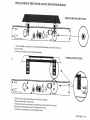
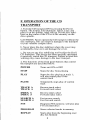
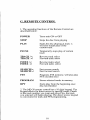
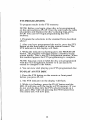
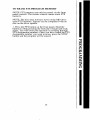
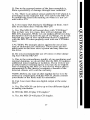
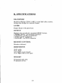
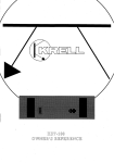
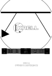
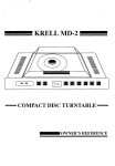
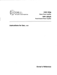
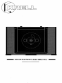
MD-20 OWNER’S REFERENCE
A. INTRODUCTION
Congratulations on your purchase of the MD-20CD
turntable and welcometo the KRELL
family of audio
components.Youhave joined a select group of listeners
whoenjoy only the finest in music reproduction.
Weare dedicated to the~ developmentof technologically
advancedcomponentstor the reproduction o,f diglt~ly
recorded music and continuing the Krell tradition ot
uncompromisedperformance through leading-edge teclanology.
This Owner’sReferenceis divided into several sections,
each designedto performa different function. Basic
installation, operation and a Questionand Answersection
are included, where answers to common
questions are
provided. Shouldyou have any questions or suggestipns,
i~lease feel free to contact yourauthorizeddealer or tlae
KRELL
staff for assistance.
In the unlikely, event that your.MD-20
should require
service youwill be pleased~to ~nowthat it is backedby a
c.omprehensiveCustomerbatistaction policy and one of
toe mostadvancedservic.e facilities in the industry. For
detailed informationon the terms and conditions of service please consult your warra,nty registration card or
your authorized KRELL
Distributor.
2
B. TABLE OF CONTENTS
3
UNPACKING AND ASSEMBLY
4
CUSTOM DUST COVER INSTALLATION
6
BASIC INSTALLATION AND CONNECTIONS
8
OPERATION OF THE CD TRANSPORT
10
REMOTE CONTROL
11
TRACK AND FTS PROGRAMMING
15
MAINTENANCE
16
QUESTIONS AND ANSWERS
18
SPECIFICATIONS
19
WARRANTYAND SERVICE INFORMATION
C. UNPACKING AND ASSEMBLY
1. Openthe box and removethe top layer of protective
foam. Thefollowing items will nowbe visibIe:
1 CDStabilizer
1 ACpower cord
1 MD-20RCRemote Control
1 Packet containing the Owner’sReference and warranty
card
NOTE:Ifany of these items are not included, please
contact your authorized dealer immediatelyf6r assistance.
2. Removethe layer of foamcontaining these items and
set it aside for later use. Carefully removethe MD-20
from its box and removethe protective plastic wrap.
NOTE:Save all packing mate.rials. If you must ship your
MD-20
in the future, repacktlae unit in its original pa.ckagingto preventtransit damage.If the unit is returnecl to
KRELL
for service, please send the cover and the remote
control unit.
CAUTION:
If your MD-20has the Custom cover do not
removethe acrylic dust cover from its protective sleeve
at this time! This cover is extremelydelicate and c.an be
permanentlyscarred if mishandled.Please follow tlae
1.nstructions providedin this Referenceafter safe installation.
3
D. CUSTOM DUST COVER
INSTALLATION
1. Standard Version SmokedTop Cover:
Removethe top cover, in its protective sleeve, from the
s.hippingfoam.Toprevents.c.ra.tching, leave tlae protective
sl.eeve on tlae top cover until t~lae cover mountingis complete. T.here are two pairs ot screws .with w~asher-type
receptacles attachedto t-he backpanel of the unit tor mounti.ng the top cover. Centerthe hingepins on the top coverov.er
toe two pairs of screws. Carefullyslide the hinges into tlae
.slots formedby the washers.Pusti the cover downevenlyon
both sides until it is fully seated. Finally, removethe
protective sleeve.
2. CustomVersion Clear Lucite Top Cover:
Removethe top cover from the protective foam and its
protectivesleeve. Th. ere are twopairs of.screwswith washertype lainge receptacl.es on the ba.ck of tlae unit. Remove
the
four screws from tlae unit and take off the black .hin.ge
receptacles. Carefullyplace the lucite top cover sucla tlaat
the circular milled-out portion is centered over the transport. Align the slots in the cover’s hinge blocks with the
holes in the backof the chassis. Threadthe four screwsinto
the chassis t.hroughthe hingeblocks: Tigh. ten dow~n
light.ly
and adjust the cover so it is centerec~on the unit. Oncethe
cover as aligned, tighten downthe supporting screws.
NOTE:
The clear lucite cover must be loweredmanually, as
it is very heavy and does not have a dampingmechanism.
4
INSTALLATION
OF THE CUSTOM ACRYLIC
DUSTCOVER FOR MD-20
REMOVEABLE MOLDED COVER
MD-20
MADE
INU.S.A.
NOU~ER
SERVICEABLE
PARTS
INSIDE
XLR
O
SPECIAL
1. To removemoldedcover, slide the cover assemblyupwarduntil the hinges are cleared from both sets of
screws and washers.
2. Be sure to save all the screwsand washersafter disassembly.
CUSTOM ACRYLIC COVER
E PARTSINSIDE
~
~
SPECIAL
1. Remove
the four original hinge retaining screwsfromthe backof the unit.
2. Remove
the three washers from each screw.
3. Gentlyplace acrylic coveron the chassis top, center the hingesto matchthe holes in the chassis.
4. Insert the four screwswithoutwashersinto the hingeand fasten loosely.
5. Center the cover with the chassis and secure hinge block screws.
SEPT.EMBER
1, 1992
E. BASIC INSTALLATION AND
CONNECTIONS
1. Place the unit on a clean, level surface awayfrom
excessive heat, moist,ure or light. Ideally, the MD-20
should be placed on tlae top of an audio componentcabinet or other "openair" rigid platform.
2. TheMD-20
may.be. placed in a cabinet. It will require.
17.0 inches of vertical clearance betweenthe bottomancl
top shelves for proper operation of the cover.
3. I.f space is limited, the MD-20
can be operated without
its clust cover. Six inches vertical clearanceis adequateto
allow convenientaccess to the disc transport area.
4. The location of the unit should be within 2 meters of
the digital signal processor.If longerdistanc, e is re~quired,
we recommend
using an AT&T
fibre optic clata linl~ o.r an
AES/EBU
balancedi:lata link, as they are moresuitecl to
long distance runs.
5. Connectthe ACpowercord to the back of the unit.
Oncethe powercord is secured, plug the cord into an AC
outlet.
6. Press the POWER
button on the front panel. The display will illuminate and the transport willnowbe active.
NOTE:While the MD-20has superb regulation and does
not require a dedicated ACcircuit, we strongly advise
against any. connectionsthrough extension cords or multiple ACai:laptors. High quality 15 ampgroundedAC
sti-ips are acceptable.
7. Connectthe Digital Output from the MD-20to a Krell
Dig!tal Processor or other compatibledigital-to-analog
aualo processor.
The MD-20is compatible with industry standard Fibre
~Optic, Coaxial RCA,AT&T
wide bandwidth Fibre Optic
bl’ type and AES/EBU
XLRoutput connectors.
NOTE:
Care should be taken in selecting the type_ of
cable used to lin.k the MD-20
to your processor. We
recommend
botla the AT&T
Fibre Optic due to its superior bandwidthand, signal isolation properties, and tile
AES/EBU
format clue to its higher voltage transmission
and noise rejection due to balancedformat.
6
CAUTION:
The MD-20is a CDTransport only. It is not
designed to connect directly to any preampor analog
signal processor.
The MD-20is equipped with a special termination system called TimeSync.TimeSyncis a system that locks.
the clock betweenthe MD-20
and specific Krell digitalto-analog processors. This connectionis labeled SIRE,
CIALon the back of the MD-20.The termination is via
an AT&T
fibre op.tic cable only and is used in con.junction with any of the other digital links like the AT&T
or
AES/EBU.
The TimeSyn.coption c.an be ordered with the MD-20or
installed at a later time by an authorizedKrell dealer or
distributer.
NOTE:The TimeSyn¢syst.em can ~ be utilized with
certain Krell digital-to-analog converters and will not
work with any other makeor model. Please consult your
dealer or the Krell staff for specific information.
NOTE:The TimeSyncoutput can not be used as an additional digital output.
TIMESYNC CONNECTION
The TimeSyncsystem is terminated via an AT&T
ST
fibre optic cable.
1. Connectthe AT&T
fibre optic cable to the termination
labeled SPECIAL
on the MD-20.Makesure the small
key at the top of the fibre optic cable is upright and fits
smoothlyinto the AT&T
receptacle, twist the collar
clockwiseto lock the cable in place.
2. Connectthe free end of the fibre optic cable to the
termination labeled Time.Sync/Extclock on the back of
your Krell digital-to-analog converter.
3. Connectyour digital interlink betweenthe transport .
and digital-to-analog converter, if not already connectecl.
4. Select a digital source and press the TimeSyncbutton
on the front of yourdigital-to- analog, converter. The
correspondingIed wilFilluminate indicating the
TimeS-yncis Iocked. Should the TimeSy_ncLED
flash,
this meansthe TimeSyncclock has not.locked and. requires, resettin.g. Select anyoth.er digital input.ontlae
cfigital-tg-analog converterancl then reselect the input.
you wisla to use. The TimeSyncLEDwill nowbe steacly
and the clock will be locked.
7
F. OPERATIONOF THE CD
TRANSPORT
1. Turn the CDtransport ONby pressing the Power
b.utton. The display will illuminate. Select a disc and.
p.lace it o.n the spindl_e, label side up. Put the disc staNIizer on the center of the CDso it fits securely on the
drive spindle.
CAUTIONS:
Never operate the CDtransport without the
disc stabilizer. This can result in damageto the transport
or your valuable compact discs.
b. Never place the disc stabilizer where the cover may
accidentally close on it and damagethe cover.
c. Donot use any disc stabilizing tool besides the Krell
CDStabilizer. This device has been specially machined
to precisely match the CDtransport. Failure to heed this
warning may cause damageto the laser transport.
2. The functions of the front panel buttons that control
the transport are described below.
POWER
Turns unit ONor OFF
STOP
Stops the disc from playing
PLAY
Starts the disc playing at. track 1;
will also restart play of the
current track
PAUSE
Tem.porarily stops play of current
track
TRACK I<
TRACK >l
Reverse track select
Forward track select
INDEX I<
INDEX >1
Reverse index select
Forward index select
SEARCH I<
SEARCH >l
Fast reverse search
Fast forward search
FTS
Programs FTS memory; will also play
FTSencoded discs
PROGRAM
Stores selected tracks in memory
REPEAT
Starts play from the beginning once
disc has finished
8
3. Select a track on the CDto play with the remotecontrol or via the front panel and press the Play button. The
music will nowbegin.
9
G.
REMOTE CONTROL
1. The operating functions of the RemoteControl are
describei:l below:
POWER
Turns unit ONor OFF
STOP
Stops the disc from playing
PLAY
Starts the disc playing at. track 1;
will also restart pIay of the
current track
PAUSE
Tem.porafily stops play of current
track
TRACK I<
TRACK >1
Reverse track select
Forward track select
INDEX I<
INDEX >1
Reverse index select
Forward index select
SEARCH I<
SEARCH >1
Fast reverse search
Fast forward search
FTS
Programs FTS memory; will also play
FTS encoded discs
PROGRAM
Stores selected tracks in memory
RPT
Starts play from the beginning once
disc has finished
2. The MD-20remote control has a 10 .dj.git keypad. The
keypadallows for direct access to specific trac.ks. Pu.nch
in the t.rack numberyou want and pressPlay, the tracl~
you selected w~ill begin playing. The direct access keypad
is convenient tor track and~FTSprogramming.
10
H.
TRACK PROGRAMMING
The remote control or the front panel of the MD-20can
be used to programspecific tracks on a disc to be played
in the order you choose. The MD-20can store up to 20
selections per program.
1. Select the track numberwhichwill start the sequence
into the keypad, then push the PROGRAM
or PROGR
button. A "P" will appear next to the track number.
2. Enter the rest of the track selections in. yourprogramin
the same manner rememberingto push the program
buttonafter eachtrack selecte~t.
3. Once you have finished your programming,push the
PROGRAM
or PROGRbutton again ending the program
sequence. The machinewill then review the tracl~s you
have selected.
4. Press the PLAY
button and the programwill begin.
Whilethe .program is running you can Pause, Search and
select trac~:s within the program.Youcan start a track
playing from the beginningby pressing the Play button.
P.ress STOP
only to defeat, or erase, ttie programfunction.
5. Press the REPEAT
button and the machinewill play
your selected tracks over again in the sameorder they
were programmed.
6. To cancel your programpush the STOPbutton.
FTS MEMORY
FTS,or Favorite TrackSelection, is a feature that enables
youto store desired tracks on a CD,in a sp~ecific order,
into
9- the memoryof the MD-20.Once you have pr
grammeda disc with FTS, the machinewill give that
specific CDa reference number. The machine remembers
.tfiis inform.ationand will play the tracks youhaveselected for that CDwith a simple command.The machine
can also play the entire disc should you choose.
11
FTS
PROGRAMMING
To program tracks in the FTS memory:
NO.TE: Before you begin,place disc to be progra.mmed
on tl~e unit and press PLAY.Oncetl~e unit reads tl~e table
of contents and displays the disc’s playing time,press
STOE You can now begin programming fhe FTS
memory.
1. Programthe selections in the standard form described
above.
. After you have progra.mmedthe tracks, press the FTS
~utton
on the front panel or on the remote control. The
FTSindicator in the display will flash.
. While the indicator is flashing press the PROGRA.M
~utton.
The machine will then display a numberon tl~e
screen briefly. This is the FTS designation number. When
this number appears the FTS programming is complete.
NOTE:You may want to label the disc you programmed
with the FTS designation numberso it can easiIy be
erased or changed-in the future.
4. You can now start
playing your FTS programmeddisc.
TO PLAY AN FTS DISC
1. Press the FTSbutton on the remote or front panel
before you press PLAY.
2. The FTSindicator on the display will flash.
3. While it is flashing, press the PLAYbutton and the
.MD-10wi.ll play_ only trie tracks in FTSmemqry.If you
do not wisl~ to play.only the FTSselected tracl~s on a
disc, press Play wltl~ out pressing the FTSbutton first.
The entire disc will nowplay.
12
TO ERASE FTS
PROGRAM MEMORY
NOT.E:FTS memorycan only be .erased via the front
panel controls. The remote control cannot erase FTS
memory.
NOTE:The disc does not have to be on the MD-20to
erase FTS memory. Erasure can be completed with no
disc on the drive spindle.
. Press the FTSbutton on the front panel. Hold the .
~u.tton
in while pressingthe forward or backward track
select. Youwill notice the machineis scrolling through
FTS des!gnation numbers. Once you have found the FTS
bdesignatlo.n
you
want
erase, press the STOP
utton and thenumber
program
will
betoerased.
13
I.
MAINTENANCE
.B. ecause of its superb build quality the MD-20
requires
little maintenance.Shouldthe unit becomeexcesslvly
dirty, clean the lens assemblywith a cameralens brush
madeof a soft material like camelhair. Theacrylic top
plate and dust cover should be cleaned with the polistiing
kit provided. Readthe directions on the containers for
best polishingresults.
REMOTE CONTROL BATTERY INSTALLATION
AND REMOVAL
The batteries in the remote control should be changed
whenthe tran.sport is no longer understan~ding9r correctly respondingto the commands
sent trom the unit.
R~e.movethe four socketcap screws from the back portion
ot tlae remotecontrol. Remove
the back plate to expose
the battery storage compartment.Refer to the polarity
drawingwhile inserting the batteries. Replacethe back
plate and insert the four socketcapscrews.
FUSE INSTALLATION AND REMOVAL
the MD-20does not seem to power-up, unplug the unit
~om
the ACwall socket and cl’/eck tlae tuse.
1. Locatethe fuse holder on the back of the unit labled
FUSE.Turn the fuse holder counterclockwise and gently
pull the fuse free fromthe chassis.
2. Checkto makesure the foil in the center of the fuse is
still connected.If youare still unsure, measurethe fuse
with an ohmmeter to determine if it is intact. The MD-20
uses a 1 ampfast-blow fuse. Shouldthe fuse need replacing, use only the fuse specified.
3. Place the fuse into .the receptacle and p_ushand tu.m
gently, clockwiseuntil the fuse holder is ~ully seated.
Plug tlae unit into the ACwall socket and press the Power
button.
CAUTION:
Should the MD-20n.ot power-up and
con.tinous.ly blowfuses, unplugtlae unit trom the ACwall
outlet and contact yourKre-ll dealer or distributor.
15
J.
QUESTIONS AND ANSWERS
Q. MyDigital to Analog processor will accommodate
eather fibre optic or coaxial digital inputs. Whichoutput
should I use on the MD-20?
A. Whilea high quality coaxial willperform quite well,
were.commend
glass fibre optic cable due to its ab.ility to
completelyisolate the grouni:ling planes betweentlae
transport and processor, and its resistance to RFinterference. If an AT&T
or AES/EBU
input is available, we
recommend
one of these interfaces be utilized.
IQ.
Whenlistening
to wrong
certainwith
discs
skipping noises.
s there
something
theI hear
MD-20?
A. Dueto the accuracyof the laser reading systemin the
MD-20,discs must be kept reasonably clean. If the disc
is mistracking, it could be becauseof excessivedirt or
fingerprints. Cleanthe disc andretry. If the disc still
skips, try severalothers. If it is onlythe first disc that is
skipping, the disc mayneed to be replaced. If the unit
mistracks on several discs, contact your Krell dealer or
distributor.
Q. I can not seemto get the FTSprogrammingfeature to
programmydiscs, is there something wrong?
A. Makesure the disc you wish to programis indexed, or
read, by the machinebefore you start your program.
Refer to the FTSprogramming
instructions in this refere.nce..Make sure whenyou are playing FTSencoded
cliscs tlaat the FTSbuttonis pr.esseit andthe display reads
FTS.If the sequenceis alterecl the MD-20
can not correctly correlate the FTSinformation.
Q. Do you recommendI leave the MD-20ONat all
times?
A. Yes, Thesecircuits are most accurate and stable when
left to idle whennot in use. In fact, discrete parts age
.faster when cycled ONand OFEThe MD-20will sound
better and last longer if left ON.
NOTE:Youshould disconnect the ACcord from the wall
outlet before any electrical storms or if you plan to be
awayfrom your homefor prolonged periods of time.
Q. Will the MD-20
play if the dust cover is fully raised?
A. Certainly. Theunit will function perfectly even with
the dust cover removed.
16
Q. Dueto the exposednature of the laser assemblyis
there a possibility of damagethrough laser radiation?
A. No. There is an optical sensor under the CDwhenit is
positioned on the transport hub. This allows the MD-20
to prohibit the laser fromturning on whenit is not covered with a CD.
a~Ile own
many
CDsdiscs
that with
have the
CDRings
on them. AmI
to use
these
MD-20?
A. Yes, TheMD-20will accept discs with :’CDRin.gs".
Dueto their very low mass, they will not damagethe
MD-20’stransport. While we can neither affirm nor deny
the b.enefits derived fromthe use of CDRing.s, wedo not
fee! that any type of disc equilibriumdevice is require.d
with the MD-20whenproperly used with our CDStabilizer.
CAUTION:
Westrongly advise against the use of any
type of additional disc stabilizer. Theseitems add too
muchmass to the laser servo system and mayburn out
the drive.
Q. Do you recommendthe use of Cones or other damping feet with the MD-20?
A. Dueto the extraordinary rigidit.y of our machiningand
internal damping,we do not fgel that the MD-20
requires
additionalrn.ass co.uplingor isolation. If youwisht.o use
an atter-market isolation device you maydo so without
fear of dam. agingthe MD-20.Anydevice which affixes
permanentlyto t-he chassis or requires a breach of the
external chassis will void the warranty.
NOTE:Before any type of after market device is to be
utilized in conjunction with the MD-20,please consult
yourdealer or the Krell staff for assistance.
Q. Can I use morethan one digital output at the same
time?
A. Yes, TheMD-20
can drive up to four different digital
to analog converters.
Q. Will the MD-20play CDsingles?
A. Yes, the MD-20will play CDsingles.
17
K. SPECIFICATIONS
TRANSPORT
Modified Philips CDM-1MK11with Hall effect
swing-arm design in a unicast frame.
LASER
Single Beamwith glass lens
OUTPUT
Digital only in industry standard SPDIFformat.
1 FIBREOPTICvia standard interface
1 COAXIALvia RCAconnector
1 AT&Tvia ST connector
1 AES/EBUvia XLRconnector
REMOTE CONTROL
Wireless infrared
DIMENSIONS
19.0" wide,
12.5" deep
6.0" high, cover closed
15.0" high with cover open
WEIGHT
20 pound_s unit only
33 pounds in box
18
motor,
L. WARRANTYAND SERVICE
INFORMATION
There are no user-serviceable parts inside the MD-20.
The MD-20has a limited warranty of three years parts
and labor on transport-related parts; five years parts and
labor on electronic parts. Returnfreight is includedin the
warranty. Thewarranty period b.egins on t~e date of
p_u_rchaseand is activated with the return ot the enclosed
Warran.tyCardand a copy of the Sales receipt. Please
return the warrantycard immediatelyafter successful
installation and operation are completed.
The warranty for Krell products is valid ~ in t,he count~ry to whichthey wereoriginally shippeda.nd at tlae
ta.ctory. If youthink there are prgblemsw!tla yourunit
please contact your dealer, distributor or the tactory
immediately.
he operatingvoltageof this unit is determ,ined by the
~a
cto_ry_and c.a.n only be changedby_an autl~.orized .
KRELL
distributer or the KR-ELL
factory. Anyunautlaoihzed
voltage cooversio~n
will void
the
warranty.
Should
e operating
voltage ot your
MD-20
require
changing,
contact KRELL
Industries.
Plea~s.e do not retur9, any unit to KRELL
for repair without first calling to discuss the problemand to obtain a
Return Authorization number.-Freightto the factory or
distributor is yourresponsibili.ty. R.~turnfreight to you
will be paid by the factory or dlstrit)utor. Anyunautlaori.’zed disassembly,.updatesor modificationsperformedto
tlae unit will voidtlae warranty.
19
t
0
I
0
0
KRELL DIGITAL INC.
35 HIGGINS DRIVE MILFORD,CT 06460
SALES203-874-3139 FAX203-878-8373
COPYRIGHT1992 KRELLDIGITAL INC.
(MD209209)