1
Quick Reference
Table of Contents:
Pages
01
cl1
13
m
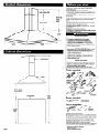
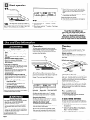
Product dimensions
Cabinet dimensions
q
Before you start
02
cl3
Venting requirements
@l
Installation steps
cl5
Use and Care Information
Electrical requirements
m
Warranty; Accessories
piiziiq
Wiring diagram
The KitchenAid Consumer Assistance Center:
The KitchenAid Consumer Assistance Center is open 24 hours a day,
7 days a week. Call l- (800) 422-1230. (The call is free within the
continental United States.)
Call the KitchenAid Consumer Assistance Center when you:
q
q
Have questions about range hood installation or operation.
Need to obtain the name and number of a KitchenAid-authorized
service company.
When you call, you will need:
q
q
The range hood model number.
The range hood serial number.
Both numbers are listed on the serial/rating
range hood on the rear wall.
5-v
plate, located inside the
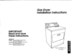
Important: Observe all governing
and ordinances.
f
t
1” min. - IO-3/8” max.
upper chimney height
codes
Proper installation is your responsibility:
Have a qualified technician install this range hood.
Comply with installation clearances specified on the
serial/rating plate.
Serial/rating plate is located inside the range hood on
the rear wall.
Range hood location should be away from strong draft
areas, such as windows, doors and strong heating
vents.
Cabinet opening dimensions that are shown must be
used. Given dimensions provide minimum clearance.
Consult your cooktop/range manufacturer installation
instructions before making any cutouts.
Grounded electrical outlet is required. See “Electrical
requirements.”
Ductwork must terminate outdoors,
All openings in ceiling and wall where range hood will
be installed must be sealed.
l
l
24-518” min. 34-314” max.
overall
chimney
height
23-518” lower
chimney height
I
t
10-l/4”
canopy
Electrical Shock Hazard
It is the customer’s responsibility:
*To contact a qualified electrical installer.
*To assure that the electrical installation is
adequate and in conformance with National
Electrical Code, ANSVNFPA 70 - latest edition’,
and all local codes and ordinances.
Failure to do so could result in fire, electrical shock
or other personal injury.
upper chimney
Electrical Shock Hazard
*Take special care cutting holes into ceiling or wall.
Electrical wires may be concealed behind the
ceiling or wall cover and contact with them could
result in electrical shock.
Locate any electrical circuits that could be
affected by the installation of this product and
disconnect power circuit.
Failure to do so could result in fire, electrical shock
or other personal injury.
lower chimney
Personal Injury Hazard
Reaching over a heated cooking surface should be
avoided. To reduce the hazard of being burned, the
range hood should extend a minimum of 5 inches
out from the bottom of the cabinet.
Reaching over a heated cooking surface could
result in a serious burn.
l
support
structure
IP
-
-
Tools needed:
/
-
canopy
-
l-1/4” drill bit
caulking gun and
\
I
saw
24” min. bottom
of canopy to
cooking surface
flat
duct tape
cooking surface
-f
8’ min. 9’ max.
ceiling
to floor
allen
wrench
Parts needed:
2 U.L.-listed, l/2” conduit
connectors
power supply cable
wall or roof cap
metal ductwork
36” base
cabinet
height
Mobile
home installation
The installation of range hood must conform to the
Manufactured Home Construction and Safety Standards,
Title 24 CFR, Part 3280 (formerly the Federal Standard
for Mobile Home Construction and Safety, Title 24, HUD
Part 280); or when such standard is not applicable, the
Standard for Manufactured Home Installation 1982
(Manufactured Home Sites, Communities and Setups),
ANSI Z225.1/NFPA 501A, or with local codes.
Four-wire power supply must be used and the appliance
wiring must be revised. See “Electrical requirements.”
Copies of the standards
l
Page 1
listed may be obtained
National Fire Protection Association
Batterymarch Park
Quincy, Massachusetts 02269
from:
For the most efficient and quiet operation:
Fire Hazard
*Terminate venting system to outside.
l Do Not terminate
the vent in an attic or other enclosed
space.
l Use only metal ductwork.
l Do Not use 4” laundry-type
wall caps.
l Do Not obstruct
the flow of combustion and ventilation
air.
Failure to follow these instructions could result in a fire.
q
It is recommended that the range be vented
vertically through the roof through 9” round
ductwork.
q
The length of ductwork and number of elbows
should be kept to a minimum to provide
efficient performance.
q
q
q
The size of the ductwork should be uniform.
q
If roof or wall cap has a damper, Do Not use
damper supplied with the range hood.
q
Use duct tape to seal all joints in the ductwork
system.
q
Use caulking to seal exterior wall or roof
opening around the cap.
Use no more than three 90” elbows.
Make sure there is a minimum of 24 inch of
straight duct between the elbows if more than
one elbow is used.
m Do Not install two elbows together.
q
Property Damage
l
l
Determine which venting method is best for your
application and follow “Installation steps” on
Page 3.
jJ 9” round duct is recommended for remote
blowers.
Before making cutouts, make sure there is proper
clearance within the wall or roof for the exhaust duct.
Do Not cut a joist or stud unless absolutely necessary.
If a joist or stud must be cut, then a supporting frame
must be constructed.
Failure to follow these instructions
property damage.
Ducting should transition to 9” round duct as
soon as possible.
may result in
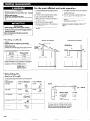
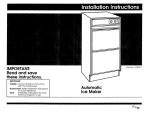
Venting methods
Vertical roof venting
Horizontal
wall venting
This range hood can be installed as either ducted or
ductless.
Ductwork needed for installation is not included.
3-l/4” x IO” rectangular, 7” round, 8” round or 9” round
ducting may be used.
Ductwork can terminate either through the roof or wall.
To vent through a wall, a 90” elbow is needed.
The ductwork length should not exceed the lengths
shown in the chart below.
Duct size
Maximum
length
3-l/4” x 10”
35 feet
7” round
40 feet
8” round
50 feet
9” round
60 feet
Ductless installations vent out the grates in the sides of
the chimney. Ductless installations require a Ductless
Installation Kit, Part Nos: 4378624 (almond),
4378625 (stainless steel),
4378626 (white),
available from your
KitchenAid dealer.
Calculating the
ductwork length
To calculate the length of the system you need, add the
equivalent feet for each ductwork piece used in the
system.
Ductwork Piece
3-l/4”
x IO” Rectangular
45” elbow
7.0 feet
.s:i:..
.,::,i;ijiig
,..:::,:p’
.,.:.;::
:~:
90” elbow
90” flat elbow
5.0 feet
3-l /4” x IO” ductwork system
7”, 8” or 9” Round
2.5 feet
..:&~
,.:,:.:.:.:.:
:.:
.~~~ii:,
5.0 feet
,f:~fiigl-::‘::i:~
..+y:,:::.
...>F.
::.::
,,.:.:3::;:sy
:::1
:.:.;:::::.:::.;:.:
@::.;::
:,:~:siigijipijii:g:
,.l):.:........~.~~
12.0 feet
....,...
.&:..
...,.,
..1.
.+>>,.
.A..
‘&,.?$>.
@..:.
.:;*;:{:A
,.,..
3-l 14” x
10” elbow
w
..:.:.:.:.:.:.:.:.:
:.:..
.:::liis:..
Maximum length
5.0 feet
=
=
=
3-l/4” x IO” system
= 13 ft.
.: ..::;:;
i;:i:g:o
jz$j:.
“:
wall cap
Page 2
0.0 feet
35 feet
1 - 90” elbow
.. i::.::;
:.:.:.:.:
>:,:::.,,
..:.::>>.......-....:i:~B:
..::‘:::::::‘:::..
..,.,.....,.,...,.....,
..) :;“‘::.,:;:::;:;:;:;:;:;
:~i.~:i:i:‘:~:i:8:i:8::::~.,
~~~~
transition to round
q
Note: Flexible ductwork is Not recommended.
If it is used, each foot of flexible ductwork used is
equivalent to two feet of straight metal ductwork
when calculating the ductwork length. (Example:
A flexible elbow equals two standard elbows.)
5ft.
8ft.
oft.
wall cap
Electrical Shock Hazard
Electrical ground is required on this
appliance.
Do Not ground to a gas pipe.
Do Not have a fuse in the neutral or
grounding circuit. A fuse in the neutral or
grounding circuit could result in electrical
shock.
9 Check with a qualified electrician if you are in
doubt as to whether the appliance is properly
grounded.
q
A U.L.-listed conduit connector must be used at
each end of the power supply cable.
q
Allow some slack in the cable so appliance can
be moved if servicing is ever necessary.
l
l
l
Failure to follow these instructions could
result in a fire, serious injury or death.
Wire sizes (COPPER ONLY) must conform with
rating of the appliance, as specified on the
serial/rating plate, and to the requirements of the
National Electrical Code, ANSI/NFPA 70-latest
edition (*See Page I), and all local codes and
ordinances.
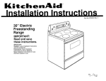
/
Emounting
template
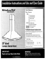
Wiring diagram is shown on the back cover of
these instructions.
support
mounting
bracket
Power cable opening
SUPPlY
cable
support
system
If codes permit and a separate grounding wire is
used, it is recommended that a qualified electrician
determine that the grounding path is adequate.
F po
Electrical Shock Hazard
q
A 120-volt, 60-Hz, AC-only, fused electrical
supply is required on a separate 15-amp circuit,
fused on both sides of the line.
Care must be taken when drilling holes into
ceiling or wall. Electrical wires may be
concealed behind the ceiling or wall covering.
q
A time-delay fuse or circuit breaker is
recommended.
Failure to do so could result in fire, electrical
shock or other personal injury.
q
q
CONNECT WITH COPPER WIRE ONLY.
Connect directly to the fused disconnect (or
circuit breaker box) through flexible, armored or
non-metallic sheathed, copper cable (with
grounding wire).
-
DI I
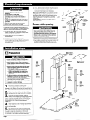
1. Determine and clearly mark a vertical centerline
on ceiling where range hood will be installed.
2. Use template to determine the proper location for
the power supply cable opening. Drill a l-1/4”
diameter hole through the ceiling at this point.
Preparation
Property/Product Damage
. Cover countertop, cooktop or range with a
thick, protective covering.
Before making cutouts, make sure there is
proper clearance within the ceiling or wall for
exhaust duct.
Because of the size and weight of this range
hood, the support system must be securely
attached to the ceiling.
- For plaster or sheet rock ceilings, the
support must be attached to joists.
- If this is not possible, you must build a
support structure behind the plaster or
sheet rock.
Do Not cut a joist or stud unless absolutely
necessary. If a joist or stud must be cut, then a
supporting frame must be constructed.
9 Securely attach support mounting bracket to
ceiling BEFORE attaching canopy.
I
Failure to follow these instructions may result
in property or product damage.
w
mounting
template
support system
l
l
l
upper +
chimney
trim
+
lower -D
chimney
trim
e
1
n
4
#J
Install ductwork. (See “Venting requirements”
section, Page 2.) Use caulking to seal exterior
wall or roof openings.
5
n
Run wiring through ceiling according to the
National Electrical Code and local codes and
ordinances. Feed enough power supply cable through
the wall to make the connections in the hood’s
terminal box. Do Not turn on power until installation
is completed. Use caulking to seal all openings.
Page 3
power
yplv
cai3le
n
upper
chimney
trim
attach
lower
chimney
-
Determine and mark the centerline on the
ceiling where the range hood will be installed.
Using the mounting template, mark the
3 n location of the support mounting bracket holes,
ductwork and power supply cable cutouts on the
ceiling. Use drill and saber saw to cut openings for
power supply cable and ductwork. (See “Venting
requirements” and “Electrical requirements,”
Pages 2-3).
.
b
Put a thick, protective covering over
n countertop, cooktop or range to protect from
damage or dirt. Select a flat surface for assembling the
unit. Cover that surface with a protective covering and
place all range hood parts and hardware on it.
2
attach upper
chimney to
support
sttGture
first
lower
chimney
trim
7
Align support mounting bracket with holes in
ceiling. Attach support system frame to
ceiling using anchors recommended for your type of
ceiling:
n
Concrete ceiling - use inserts and screws
provided.
Wood ceiling - use 4” long wood screws.
Plaster or sheet rock ceiling - attach support
mounting bracket to ceiling joists if possible. If
ceiling joists are not available, you must build a
supporting structure behind the plaster or sheet
rock.
l
l
l
screws
Make sure the support is connected firmly to
ceiling.
9
Press on
handle in front of
filters to release filters
from range hood
canopy. Remove filters
and set aside.
10
Remove the terminal box cover from the
range hood. Remove the power supply
cable knockout using a flat-blade screwdriver.
Attach conduit connector into power supply cable
opening so that conduit connector clamping screws
are inside the terminal box.
I
6
n
n
Personal Injury Hazard
Because of the weight and size of the range
hood canopy, two or more people are needed to
move and safely install the range hood canopy.
Failure to lift range hood properly could result
in damage to the product or personal injury.
Remove the four screws on the upper
chimney and disassemble chimney pieces
from support frame.
n
four set
Personal Injury Hazard
Because of the size and weight of this range
hood, the support must be firmly attached to the
ceiling.
For plaster or sheet rock ceilings, the support
must be attached to joists. If this is not
possible, you must build a support structure
behind the plaster or sheet rock.
Make sure the support is connected firmly to
ceiling.
. Firmly tighten all four set screws before
attaching canopy.
l
l
Failure to follow these instructions could lead to
personal injury or property damage.
8
Determine the height of the canopy. The
range hood requires at least 24 inches of
clearance between bottom of range hood canopy
and cooking surface.
n
The bottom of the canopy will be approximately 9
inches below the bottom of the support system. To
change the canopy height, loosen the four set
screws on the support frame. Adjust support frame
to the desired length and tighten all four set
screws firmly in place before attaching canopy.
located next to
exhaust opening so that there is
approximately l/4 inch space between bolt head
and canopy. Lift canopy and insert bolts into slots
in support system frame. Tighten bolts to support
system frame and canopy.
Electrical connection
12
Electrical Shock Hazard
l
Electrical ground is required on this
the appliance is permanently grounded.
. Disconnect power to the junction box before
making the electrical connection.
*This appliance must be connected to a
grounded, metallic, permanent wiring
system, or a grounding connector should be
connected to the grounding terminal or wire
lead on the appliance.
q
q
q
n
q
Connect the white wire of the power supply
cable with the white lead in the range hood,
using a twist-on connector; connect the black
wire of the power supply cable with the black
lead in the range hood, using a twist-on
connector.
q
Connect the power supply green (green and
yellow) grounding wire under the green,
grounding screw.
q
q
Tighten conduit connector screws.
Make electrical connection:
Disconnect power supply.
Feed enough power supply cable through
conduit connector to make electrical
connections.
Connect the power supply cable to range hood
terminal box through the U.L.-listed conduit
connector.
Replace the terminal box cover.
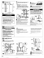
Install chimney
sections
13
Attach damper to exhaust opening on
top of the canopy using two Phillipshead screws. Connect ductwork to damper and
seal all connections with duct tape.
n
chimney
screw
15
16
Cut upper chimney trim to correct length.
Attach trim strips with clips to cover
chimney seam.
14
Page 4
n
Position upper chimney section on
support system frame.
section. Check for proper position. Then secure
upper and lower chimney sections to support
system frame with four screws.
position.
n
n
Place filters in canopy opening so rear
edge is over flange. Press filters up into
Check operation
17
n
Turn power on.
I
q
Move the blower speed switch to the far left;
blower speed should be LOW. Move blower
speed to right; blower speed should gradually
increase until you reach HIGH speed at far
right.
q
Move blower and light switches to “0” position
to turn blower and light off.
1
” IQ I-w@
,
4: 0 1
4-O
I
-mma1
Gs 01
-\
light switch
19
18
The range hood controls are located in a
grey panel on underside of the canopy. To
open the panel, press on the front edge of panel and
release. The control panel will drop down.
n
blower switch
blower speed switch
q
Check that the circuit breaker is not tripped or
the house fuse blown.
Check the operation of the range hood:
q
Move light switch to “1” position.
should turn on.
q
Move blower switch to “1” position.
should operate.
n
If range hood does not operate:
The light
The blower
To get the most efficient use
from your new range hood, read the
“Use and Care Information”
section.
Keep your KitchenAid Installation
Instructions
and Use and Care Guide
close to range hood for easy reference.
Grease Fire Hazard
To reduce the risk of a range top grease fire:
. Keep fan, filters and grease-laden surfaces
clean.
Always turn hood ON when cooking at high
heat.
Only use high heat setting on range when
necessary.
Use low to medium setting to heat oil.
Never leave range unattended when cooking.
Always use cookware and utensils
appropriate to the type and amount of food
being prepared.
Operation
Cleaning
The range hood is designed to remove smoke,
cooking vapors and odors from the cooktop area.
For best results, start the range hood before
cooking and allow it to operate several minutes
after the cooking is complete to clear all smoke
and odors from the kitchen.
Filters:
The filters should be washed frequently. Place
metal filters in dishwasher or hot detergent
solution to clean.
Exterior
surfaces:
l
Clean the range hood with a mild detergent and
soft cloth. Do Not use abrasive cleanser or steel
wool pads.
l
l
Maintenance
l
l
In the event of a grease fire:
l
l
l
l
l
Smother flames with a tight-fitting lid, cookie
sheet or metal tray. Then turn off the
element/burner.
Evacuate and call the fire department if the
flames do not go out immediately.
Never pick up a flaming pan. You could be
seriously burned.
Do Not extinguish flames with water, wet
dishcloths or towels. Water creates a violent
steam explosion that could cause serious
burns.
ONLY use a fire extinguisher
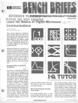
Opening
the range hood control
The range hood controls are located in a grey
panel on the underside of the canopy. To open the
panel, press on the front edge of panel and
release. The control panel will drop down.
if:
1. It is a Class ABC extinguisher
know how to use it.
and you
2. The fire is small and contained in the
area where it started.
3. You have called the fire department.
4. You can fight the fire with your back to
an exit.
Failure to take these precautions could lead to
serious personal injury or death.
” I-QI-w@ -i-Q I II
:6: 0 1
light switch
Operating
Operating
. Use range hood only
by the manufacturer.
about its use, contact
Consumer Assistance
in the manner intended
If you have questions
the KitchenAid
Center.
9 Disconnect power at service panel and lock
service panel before servicing or cleaning
unit.
9 If any electrical problem becomes evident
during use, disconnect power to range hood
at fuse or circuit breaker box.
Failure to follow these instructions
in electrical shock or fire.
Page 5
could result
Replacing
the light bulb:
Remove the retainer clips from both ends of the
light cover. Carefully slide the cover all the way to
the right. Then lower the left end of the glass
below the support flange and remove the glass by
sliding it back from the left.
Install a new fluorescent
-mmmm
@ 01
blower switch
blower speed switch
the light:
ON: Move the light switch to the “1” position.
OFF: Move the light switch to the “0” position.
Electrical Shock Hazard
clips
panel:
the blower:
ON: Move the blower switch to the “1 rr position.
OFF: Move the blower switch to the “0” position.
Adjusting
the blower
speed:
The blower has variable speed control.
Move the switch to the far left for LOW speed and
to the far right for HIGH speed.
Closing the range hood control
Position the right end of the light cover over the
flange and slide the cover all the way to the right.
Position the left end of the light cover over the
flange and slide the cover back to left. Reinstall
the retainer clips.
For assistance:
If you have questions about operating, cleaning or
maintaining your range hood:
q Call the KitchenAid Consumer Assistance
Center, l-(800) 422-l 230.
If you need service:
Maintain the quality built into your appliance by
calling a KitchenAid-authorized
service company.
To obtain the name and number of an authorized
service company:
q
q
panel:
Push up on the front edge of the control panel.
The control panel will slide up into the canopy.
light bulb.
q
Contact the dealer from whom you purchased
the appliance;
Look in the Yellow Pages of your telephone
directory under “Appliances - Household Major - Service and Repair;”
Call the KitchenAid Consumer Assistance
Center, l-(800) 422-l 230.
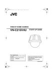
Internal blower
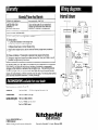
KitchenAid@ Range Hood Warranty
LENGTH OF WARRANTY
KitchenAid
LIMITED ONE-YEAR
WARRANTY
From Date of Purchase
Labor and any parts of your range hood
(except light bulbs and filters) which are
defective in materials or workmanship.
KitchenAid
WILL PAY FOR
Slide
WILL NOT PAY FOR
A. Consumable
parts such as light bulbs and filters.
B. Service calls to:
1. Correct the installation
of the range hood.
2. Instruct you how to use the range hood.
3. Replace house fuses or correct house wiring.
C. Repairs when range hood is used in other than normal,
use.
I \?
I
I
I
I
I
Lee---
Switches
B
I
r
k
single-family
household
1
D. Pickup and delivery. This product is designed to be repaired in the home.
E. Damage to range hood caused by accident, misuse, fire, flood, act of God or use of
products not approved by KitchenAid.
KITCHENAID SHALL NOT BE LIABLE FOR INCIDENTAL OR CONSEQUENTIAL
DAMAGES.
Some states do not allow the exclusion or limitation of incidental or consequential
damages so this limitation
or exclusion may not apply to you. This warranty gives you
specific legal rights, and you may also have other rights which vary from state to state.
Outside the United States, a different warranty may also apply. For details, please contact
your franchised KitchenAid distributor
or military exchange.
ELU
3
BLU /I- 5
i
I-
FLUORESCENT
LFlllP
FLUORESCENT
LAMP
-
2
Note: Instructions
are included with each kit.
Utensil Bar:
Part No. 4378619 -
15” (38 cm) long (stainless steel only).
Charcoal Filters:
Part No. 4378623 (2 per pkg.)
BLOWER ROTOR
B/SBK-0128
.-----L--------------
LINE
128
Ductless Venting Kits:
68HZ
Part No. 4378624 (almond)
Part No. 4378625 (stainless steel)
Part No. 4378626 (white)
Part No. 68995521883298 Rev. A
0 1997 KitchenAid
8 KitchenAid Registered Trademark of KitchenAid.
HOME APPLIANCES
Prepared by KitchenAid, St. Joseph, Michigan 49085
IN
URC