1
E
L
I
T
E
®
ilator
Use & Care / installation Manual
VE
Or
Manual de uso y cuidado /instalaci6n
Models
Modelos
233.59960400
233.59966400
o
u
O
99043579B
Sears, Roebuck and Co., Hoffman Estates, UL60179 U.S.A.
www.sears.com
SECTION .....................................................................
PAGE
Warranty ..............................................................................
2
Safety Instructions ...............................................................
2
Operation .............................................................................
3
Cleaning, Servicing ............................................................
3
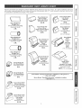
Parts Included With Downdraft ...........................................
4
Tools Needed For Installation ............................................
4
Equivalent Duct Length Chart ............................................
Prepare The Downdraft Location .......................................
Prepare The Downdraft ......................................................
Install The Downdraft ..........................................................
Connect The Wiring ............................................................
Complete The Installation .................................................
Master Protection Agreements .........................................
Service Parts .....................................................................
5
6
7
8
9
10
10
11
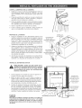
,A FOR DOMESTIC
WARNING
A
A
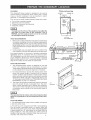
To reduce the risk of burns or ignition of clothing by reaching
across burners, the downdraft remote control MUST be mounted
in the countertop - at least 4" from the burners. See "INSTALL
COOKTOP" section on page 8.
TO REDUCE THE R_SK OF RRE, ELECTRIC SHOCK, OR
_NJURY TO PERSONS, OBSERVE THE FOLLOWING:
1. Use this unit only in the manner intended
by the
manufacturer.
If you have questions,
contact
the
manufacturer at the address listed in the warranty.
2. Before servicing or cleaning unit, switch power off at
service panel and lock the service disconnecting means
to prevent power from being switched on accidentally.
When the service disconnecting means cannot be locked,
securely fasten a prominent warning device, such as a
tag, to the service panel.
3. Installation work and electrical wiring must be done by a
qualified person(s) in accordance with all applicable codes
and standards, including fire-rated codes and standards.
4. Sufficient
air is needed for proper combustion
and
exhausting of gases through the flue (chimney) of fuel
burning equipment to prevent backdraftlng.
Follow the
heating equipment manufacturer's guideline and safety
standards such as those published by the National Fire
Protection Association (NFPA), and the American Society
for Heating, Refrigeration and Air Conditioning Engineers
(ASHRAE), and the local code authorities.
5. When cutting or drilling into wail or ceiling, do not damage
electrical wiring and other hidden utilities.
6. Do not use this unit with an additional speed control device.
7. Ducted fans must always be vented to the outdoors.
8. To reduce the risk of fire, use only metal ductwork.
9. Do not install this product with the activating switch directly
behind a burner or element. Minimum distance between
the switch and the edge of the burner should be 4 inches.
10. Loose-fitting or hanging clothing should never be worn
when operating this appliance. They may be ignited by
burners/elements on cooktop.
11. Children should not be left alone or unattended in the
area where this appliance is in use.
12. When flaming foods, turn the biower OFF. An operating
blower may spread the flames.
13. This unit must be grounded.
2
If within 1 year from the date of installation, any part of this
downdraft fails to function properly due to a defect in materia!
or workmanship, Sears will repair the part or furnish and
install a new part, free of charge.
FULL 30-DAY WARRANTY ON FINISH ON PAINTED OR
BRIGHT METAL PARTS
If within 30 days from the date of installation, the finish on any
painted or bright metal parts of this downdraft is defective in
material or workmanship, Sears will furnish and install a new
part, free of charge.
WARRANTY SERVICE _S AVAILABLE BY CONTACTING
THE NEAREST SEARS SEWOE CENTER/DEPARTMENT
IN THE UNITED STATES.
This warranty applies only while this product is in use in the
United States. This warranty gives you specific legal rights
and you may have other rights which vary from state to state.
Sears, Roebuck and Co., Dept 817WA, Hoffman Estates,
IL 60179
COOKING
WARNING
ONLY
A
A
TO REDUCE THE RISK OF A RANGE TOP GREASE FIRE:
1. Never leave surface units unattended at high settings.
Boilovers cause smoking and greasy spillovers that may
ignite. Heat oils slowly on low or medium settings.
2. Always turn hood ON when cooking at high heat or when
cooking flaming foods.
3. Clean ventilating fans frequently. Grease should not be
allowed to accumulate on fan or filter.
4. Use proper pan size. Always use cookware appropriate
for the size of the surface element.
TO REDUCE THE RISK OF INJURY TO PERSONS IN THE
EVENT OF A RANGE TOP GREASE FIRE, OBSERVE THE
FOLLOWING:*
1. SMOTHER FLAMES with a close-fitting lid, cookie sheet,
or metal tray, then turn off the burner. BE CAREFUL TO
PREVENT BURNS. If the flames do not go out immediately,
EVACUATE AND CALL THE FIRE DEPARTMENT.
2. NEVER PICK UPA FLAMING PAN - You may be burned.
3. DO NOT USE WATER, including wet dishcloths or towels
- a violent steam explosion will result.
4. Use an extinguisher ONLY if:
A. You know you have a Class ABC extinguisher and you
already know how to operate it.
B. The fire is small and contained in the area where it
started.
C. The fire department is being called.
D. You can fight the fire with your back to an exit.
* Based on "Kitchen Firesafety Tips" published by NFPA.
CAUTION
A
1. For general ventilating use only. Do not use to exhaust
hazardous or explosive materials and vapors.
2. To avoid motor bearing damage and noisy and/or
unbalanced impellers, keep drywall spray, construction
dust, etc. off power unit.
3. Clean filters and grease-laden surfaces frequently.
4. Do not repair or replace any part of this appliance unless
specifically recommended in this manual. Atl other servicing
should be done by a qualified technician.
5. Please read specification
label on product for further
information and requirements.
Always
turnthedowndraft
blower
onbefore
youbegincookingtoestabIish
anairflowinthekitchen.
LetthebIower
runfor
a fewminutes
tocleantheairafteryouturnthecooktop
off.
Thiswillkeepthewholekitchen
cleaner
andbrighter.
CONTROLS
WARNING:
Always
disconnect
supply
before
cleaning
unit.
electric power
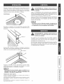
Use a mild detergent suitable for painted surfaces. DO NOT
USE ABRASWE CLOTH, STEEL WOOL PADS, OR SCOURING POWDERS. Vacuum blower to clean. Do not immerse
blower in water.
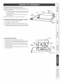
Wash the 2 aluminum grease filters in a mild detergent solution or a dishwasher. Remove them from the air vent by grasping the tab at the top of each filter.
Turnthedowndraft
blower
ONbypressing
downontheactivatingswitch.
Theairventwillrise.
The filters are different sizes. Be sure to repBace them as
removed (wider one on the meft),with tabs UP.
\
_
ARNING:
Atways
disconnect
supply
before
servicing
unit.
electric power
It may be necessary to remove the downdraft blower system
from the cabinet in order to service components such as the
blower motor or air vent mechanism.
Disconnect power to the cooktop and remove it first. Reverse
the steps under "MOUNT THE UNIT" to remove the downdraft
from the cabinet.
The blower can be turned ON or OFF and its speed can be
adjusted with the recessed knob on the right side of the air
vent.
Turn the downdraft blower OFF by pressing the activating
switch again. The air vent will go down and the blower will
shut OFF.
B
For most convenient
operation, set the bmower to your
favorite speed. The bmower will come on to this speed
whenever the activating switch is pressed and the air
vent rises.
t_
HEAT SENTRY
When chimney is UP and blower is ON (at any speed) or OFF:
If the exhaust temperature becomes higher than expected,
the Heat Sentry mode will activate and increase the blower
speed to HIGH.
Lowering the chimney
Sentry is active.
will turn blower OFF _ even if Heat
{b
2
B"
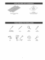
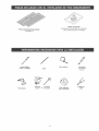
Aluminum
Grease Filters
(Qty. 2)
J
J
Screwdriver
(Fmat& Phillips)
Drill
Parts Bag
(Contains leveling brackets
& mounting hardware.)
Pencil
Sabre
Saw
-or=
Keyhome
Saw
Q
S
Tape
Measure
1/4"
Nutdriver
Duet Tape
Wire
Stripper
Kenmore
downdrafts
aredesigned
toperform
efficiently
whenattached
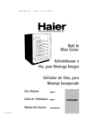
toIongrunsofduct=Asa pointofreference,
thishood
wiIIfunction
atapproximately
80%ofitsratedairflowwhen200equivalent
feetof7"roundductwork
isattached=
Usethischart
tocalculate
theequivalent
ductlengthofyoursystem=
Broan Model 428
3¼-in, × 10-in,
Right-angme Embow
Equivalent length
_
64n= Round
Wall Cap
Equivalent
Sears
Modemlength
59691
34 ft.
8.5 ft.
BroanModem
401
StraightDuct
(6-fL w/o damper)
3¼qn. x lOqn. x 2-ft, long
Equivalent length
O_
2ft.
D
3¼oin, × lO-in.
Right=angle Fiat Elbow
Broan
_lodelIength
429
Equivalent
7=in° Round
Wall Cap
Equivalent
length
Broan
ModeB
847
24 ft.
34 ft.
(6-fL w/o damper)
Broan Modem 408
Straight Duct
8=in. round × 2-ft. long
EquivaIent length
2ft°
3¼=in, × lOqn,
Right=angle
Short
Eave Embow
quivalent Iength
15ft.
Broan Modem 407
Straight Duct
7qn. round × 2-ft° long
EquivaIent length
2ft°
6qn. Round Elbow
Broan Modem
419
EquivaIent
length
8 ft.
2
45 ft.
(7-ft= w/o damper)
Broan Model 431
3¼qn. × lO=in,
Right-angle
Long
Eave Elbow
quivaIent length
15 ft.
8 ft.
7qn° Round Elbow
Broan
Modem
4!5
EquivaIent
length
Sears Modem
59391
3¼=in° ×
lO-in,
Wamm
Cap
Equivalent
length
Broan Model 430
Sears Modet "Ducting
Accessories"
available
1-800-4-MY-HOME _
_,lodel 59091
Roof Cap
(accepts 7-in° round
or 3¼qn° × !O-in, duct)
Equivalent length
30 ft. (7-ft= w/o damper)
by calling
Sears at
Broan Model "Ducting Accessories"
avaHabme by calling:
1=800=558=1711°
Sears Model 59581
3¼=in. × lO=in° to
6qn. Round Transition
Equivalent Iength
5.5 ft.
t_
re
Broan Model 412H
3¼=in, × lO-in, to
7=inoRound
Transition
Equivalent Iength
5.5 ft.
(b
2
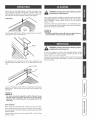
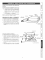
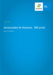
PLANNtNG
This downdraft blower system
exhaust airborne contaminants
of gas or electric cooktops. It
peninsula, or conventional walI
TYPICAL
_NSTA_ON
is designed to be used to
when cooking with a variety
can be mounted in island,
locations.
This unit can be easily installed following these basic steps:
® Cut out the countertop opening.
® Mount the unit in the cabinet.
® Connect the ductwork and electrical.
o Install the cooktop.
The high level of air flow of tHs appliance may affect the
gas flame on some types of gas cooktops°
This is
NORMAL and win cause no harm, but can be corrected
by lowering the speed of the blower.
3.1t_* X 10"
DUCT CONNE_CTOR
TAKE MEASUREMENTS
1= Refer to the cooktop installation instructions for dimensions
of cooktop, countertop cut-out, and cabinet requirements.
The Model 59960 will fit in most 30" wide cabinets and the
Model 59966 will fit in most 36" wide cabinets. However, it
is recommended that oversized cabinets be used for easier
installation.
2= Cooktop depth can vary greatly from one to another. This
may cause the fit of these two appliances to be rather tight.
Pay special attention to the areas of potential interference
highlighted above. A countertop with (A) a raised Iip and/or
(B) a backsplash may not allow enough flat countertop for a
proper installation. Note that 2" of fiat countertop is required
behind cooktop and that 1-3/4" is necessary between the back
edge of the cooktop and the inside of cabinet back.
A
f
DOWN@RAFT*"
1¢4f/1,_
-
PLAN THE DUCTWORK
1= This downdraft blower system is designed for use with
3-1/4" x 10" ductwork (can be transitioned to 6" round).
Three different discharge directions are available with sideto-side adiustment for accurate alignment of ductwork.
2. For best performance: Choose the ducting option which
allows the shortest length of ductwork and a minimum
number of elbows and transitions. Check location of floor
ioists, walI studs, electrical wiring or plumbing for possible
interference. NOTE: The unit is shipped with the 3q/4" x
10" discharge facing DOWN. See "CHANGING BLOWER
DISCHARGE" on page 7, if necessary.
3. The system wiII operate most efficiently when the ductwork
does not exceed 40 feet of equivalent duct. The chart,
above, shows equivalent feet of eibows and transitions.
The number of feet of straight duct pius the equivalent feet
of transitions and/or elbows to be used should equal 40
feet or less.
The equivalent feet of various roof and wan caps has been
taken into consideration° Do not include them in this camcumation.
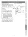
PLAN THE WiRiNG
1= The downdraft blower system draws 4 AMPS and requires
a 120 VAC, 60 Hz circuiL
2= The unit has a 2 fL long power cord with a 3-pronged plug.
Plan to provide a grounded outlet in a location which wiiI
allow the unit's power cord to reach= (Note: If the Model 59940
is being instalIed in a 30" wide cabinet or the Model 59946 is
being installed in a 36" wide cabinet, the outlet cannot be
located on the back waII of cabinet.) Outlet may also be waif
mounted, with access hole in cabinet.
6
LE_
D_SCHARGE
fRONTTO_CK
__
tasJ#eCASIN_T#EPT_ /
I
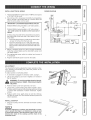
CHANGING
BLOWER
DISCHARGE
(Optiona0
Theblower
is shipped
withitsdischarge
facingDOWN.
FoF
lowthesestepsONLY
if:
o theposition
oftheblower
discharge
needs
tobemoved
soductwork
doesnotinterfere
withfloorjoists,plumbingorwiringbelow.
® itis necessary
torotatetheblower
discharge
tothe
RIGHT
orLEFT.
Placetheunitonitsbackona tableorworksurface.
BLOWER
NUTS
CLAMP
DOWN DISCHARGE o MOVING BLOWER LEFT OR R_GHT
1. Loosen the 4 nuts and 2 clamp channels.
2. Slide blower to desired position.
3. Use supplied cover plate to close open space (if any).
BOTTOM
FLANGE
4. Tighten nuts to secure top of blower and use sheet metal
screws through bottom flange to secure bottom of blower.
LEFT OR RIGHT DISCHARGE
1. Remove the 4 nuts and 2 clamp channels.
2. Carefully lift blower and disconnect motor plug if necessary.
Reposition blower and RECONNECT MOTOR PLUG.
3. Use supplied cover plate to close open space (if any).
NUT
4. Replace clamp channels and use nuts to secure the blower
in its new position.
_b
5. Use sheet metal screws through bottom flange to secure
bottom of blower.
t_
tD
_b
2
7
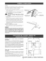
CUT COUNTERTOP
OPENING
1. Lay out and cut the cooktop cut-out far enough FORWARD
so downdraft will fit behind it.
2. Set cooktop in place and slide it as far forward as possible.
Center and square it with edges of countertop.
3. Place the plastic template against the back flange of the
cooktop and center it. Trace around template to mark the
downdraft opening.
4. Remove cooktop from countertop.
5. Cut downdraft opening. Be careful not to chip edges of
countertop.
MOUNT THE UNiT
1. Set downdraft into opening. Extend bveting brackets to
floor of cabinet so downdraft sits straight. (Note: Leveling
brackets can be removed and re-attached
in other
positions. Bottom flange may have to face inward in tight
cabinet installations.)
2. Secure the downdraft to the countertop as follows: Hold
the downdraft against the back of countertop cut-out and
tightening the 2 mounting screws (one on each end of
unit) on underside of countertop. Use a wood shim between
screw and underside of granite countertops.
3. Screw leveling brackets to bottom of cabinet. Tighten
screws holding leveling bracket to unit on each side.
MOUNTING
SCREWS
LEVELING
BRACKET
FLANGE FACING iN
INSTALL DUCTWORK
CAUTION:
BEFORE CUTTING HOLE tN CABINET
FOR DUCTWORK: Check for interference with floor
joists, wall studs, emectricamwiring or plumbing,
1. Cut hole in cabinet as well as holes in wail or floor as
necessary.
2. Mount the roof or wail cap and work back towards the
cabinet, attaching all ductwork, elbows and transitions as
previously planned. Tape all ductwork connections to make
them secure and air tight.
3. Connect ductwork (and transition, if required) to downdraft.
If necessary, LOOSEN nuts and screws that hold the blower
in place, and slide blower left or right to meet ductwork.
Re-tighten screws and nuts.
6" RD.
ELBOW
&
DUCTWORK
A 3-!/4" × 10" collar is provided for installers who prefer to
rivet the ductwork to the unit. This will allow blower to be
removed and repBaced easily in service situations without
disturbing ductwork,
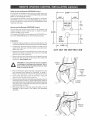
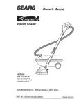
_NSTALL ELECTRICAL
W_RING
WIRING D_AGRAM
1. The Downdraft Blower system draws 4 AMPS and requires
a 120 VAC, 60 Hz circuit.
2. The unit has a 18 in. Iong power cord with a 3-pronged plug.
Plan to provide a grounded outlet in a location which will
allow the unit's power cord to reach.
UNE
tMPORTANT - LOCATION OF ELECTRICAL OUTLET:
If Model 59960 is being installed in a 30" wide cabineL_
or-
If Model 59966 is being installed in a 36" wide cabinet._
...the outlet cannot be mocated on the back wall of
cabinet.
in these cases, the width of the downdraft covers nearly
the entire width of the back waII of the cabinet. So you
must either:
,, mount the electricat box to a side wall or cabinet floor
- at least 12 inches from the back wail.
,, mount the electrical box to a wall stud behind the
cabinet - where it wilI not be covered by the downd raft.
Then provide a clearance hole in the back wail of the
cabinet.
2
3. Mount a standard wiring box, with 3-pronged receptacle,
inside the cabinet. Make sure the downdraft's power cord
can easily reach it.
4. Run appropriate power cable into cabinet and connect it
to receptacle.
5. Plug the downdraft's power cord into the outlet.
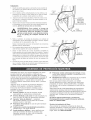
ADJUSTMENT
(b
The downdraft is factory-adjusted for proper operation. However, shipping and handling may affect the position of the
activating switch.
To adjust position of activating switch:
1. if downdraft is plugged into electrical outlet, unplug it.
S"
2. Lift air vent straight up and cock it slightly so it remains in
the UP position.
WARNING:
To avoid possible
electrical
personal
injury or death - Disconnect
caJ power.
shock,
etectri-
COV&R
3. Remove switch cover from right end of air vent.
4. Loosen the 2 screws holding the switch bracket in place.
Position switch bracket so that activating switch just comes
in contact with underside of switch membrane. Tighten
screws.
5. Repiace switch cover, gently iower air vent into chimney,
and plug in power cord. Re-connect electricai power and
check operation.
_NSTALL COOKTOP
1. Align the cooktop with the downdraft and fasten cooktop
in place.
_b
Accurate aBignment of cooktop and downdraft is necessary to ensure that there is no interference when air vent
is raised and Ioweredo There should be a gap of 1/32"-1/16"
between the back of the cooktop and the front of the
downdraft cover.
WhentousetheRemoteUP/DOWN
ControJ
TheRemote
UP/DOWN
Controlshould be used when
your
cooktop has a burner that is within 4 inches of the UP/DOWN
Button on the downdraft chimney.
The Remote UP/DOWN Control can be used for convenient
UP/DOWN operation of the downdraft chimney (even when a
burner is more than 4 inches from the UP/DOWN Button of the
downdraft chimney).
How to use the Remote
UP/DOWN
2.000
--f-
.250 DIA.
HOLES
.750
Contro!
Do net place the remote control where it wiII interfere with
cooking, where hot pans couId be set, or where hot liquids
could be spilled on the control.
The Remote UP/DOWN Control disables the UP/DOWN function of the UP/DOWN Button on the downdraft chimney.
2.000
Installation
1. Using the template at right, lay out the 3-hole pattern on the
counter top. Mark the centers of the three holes to be drilled.
2. Carefully drill the three holes through the counter top. Be
careful not to damage or chip the counter top surface when
drilling the holes.
3. Remove the control from the plastic bag. Line the control up
with the three holes and position the control so it is parallel
with the front of the counter top.
4. Remove the two nylon thumbnuts from the plastic bag and
thread onto the two studs on the control from below the
counter top. Hand tighten only.
WARNING: To reduce the risk of burns or ignition
of clothing by reaching across burners, the remote control must be mounted at least 4" away
from any cook top burner.
CUT OUT ON DOTTED
UNE
WIRING
BOX
LOWER
RIGHT
SIDE
OF
DOWNDRAFT
5. Remove the blower, clamp channels, and gearmotor cover
from downdraft (see"Prepare the Downdraft" on page 5).
Remove the large panel to expose the downdraft's wiring.
6. At the lower right hand corner of downdraft, unplug the
cabIe from the left side of the wiring box.
7. Remove remote cable from the plastic bag and plug into back of
control from below counter top. Route cable through cabinet to
lower right hand corner of downdraft and through the clearance
holes in the side of downdraft and wiring box. Plug cable into
circuit board plug, as shown=
8. Stuff excess cable out of the way, secure the cable so it is not
damaged by items stored in the cabinet, and reassemble
downdraft.
CABINET
FLOOR
WIRING
BOX
REMOTE
CABLE
Congratulations
on making a smart purchase. Your new
Kenmore ® product is designed and manufactured for years
of dependable operation. But like all products, it may
require preventive maintenance or repair from time to time=
That's when having a Master Protection Agreement can
save you money and aggravation.
_,/
Fast help by phone - phone support from a Sears
technician on products requiring in-home repair, plus
convenient repair scheduling
Power surge protection
against electrical damage
due to power fluctuations
Purchase a Master Protection Agreement now and protect
yourself from unexpected hassle and expense.
_/
Rental reiroburseroent
if repair of your covered
product takes longer than promised
The Master Protection Agreement also helps extend the life
of your new product= Here's what's included in the Agreement:
Once you purchase the Agreement, a simple phone call is
all that it takes for you to schedule service. You can call
anytime day or night, or schedule a service appointment
online,
Expert service by our 12,OOO professional repair
specialists
Uniiroited service and no charge for parts and labor
on ali covered repairs
"Noqeroon" guarantee - replacement
of your covered product if four or more product failures
occur within twelve months
Product
fixed
replaceroent
if your covered product can't be
Annual Preventive Maintenance
request - no extra charge
Check
at your
Sears has over 12,OOOprofessional repair specialists, who
have access to over 4.5 million quality parts and accessories. That's the kind of professionalism you can count on to
help prolong the life of your new purchase for years to
come. Purchase your Master Protection Agreement today!
Some ffroitations and exclusions appByo
For prices and additional inforroation call
1=8OO=827=6655.
Sears Installation Service
For Sears professional installation of home
appliances, garage door openers, water heaters, and other
major home items, in the U=S=A=call 1-8OO=44VlY=HOME®
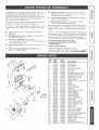
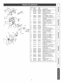
KEY
30N
NO. WIDTH
36N
WIDTH
1
2
3
4
5
6
7
8
9
10
11
12
13
14
15
16
17
18
19
20
21
22
23
24
20
27
28
29
30
31
32
33
34
35
36
37
35
39
46
97018668
99140195
99230345
97015971
97015874
98009358
97015973
98010013
99160421
99160419
99271218
99150471
97015842
99710032
99111184
97015975
99271210
99400060
99271295
99271292
99271291
97015674
97015977
99080542
98009801
97016670
98008158
98009773
99280488
97015700
98008150
98008157
98008167
99080362
99020247
99100484
99289477
99030323
98010010
11
97016667
99140195
99230345
97015970
97015874
98009358
97015973
98010013
99160421
99180419
99271218
99150471
97015841
99710032
99111184
97015974
99271210
99400060
99271295
99271292
99271291
97015674
97015977
99080518
98009802
97016669
98008158
98009778
99280488
97015700
98008150
98008157
98008167
99080362
99020247
99100484
99260477
99030323
98010010
DESCRiPTiON
TOP COVER
FILTERSPRING
POP RIVET
CHIMNEYWELDMENT
ENDCAP RH
ENDCAP LR
MACHINEDCHIMNEYSLIDE
MACHINEDAIRBOXSLIDE
SCREWRRM8-32x .375
SCREW8-32 x ..500PHL
GROUNDWIRE
SCREW10-32x .500TYPCA PH
FILTER
SPACER
SLIDE STRIPS
AIRBOXWELDMENT
CORD SET
STRAIN RELIEF BUSHING
WIRE HARNESS
SWITCH ASSEMBLY
CONTROLBOARD
CRANK ASSEMBLY
GEAR MOTOR BRACKET
GEAR MOTOR
FRONTAIRBOXBOTTOM
GEAR MOTOR COVER
AIRBOX OPENING COVER
AIRBOX CLAMP
WHIZNUT10-24
SCROLL BOX ASSEMBLY
SCROLL BOX COVER
CAPACITORCLAMP
EXT- SCROLLBOX WELDMENT
MOTORW/CAPACITOR
BLOWERWHEEL
MOTORMOUNTISOLATOR
WHIZNUT1/4-20
THERMOSTAT
THERMOSTAT BRACKET
_b
SECCION ................................................................
PAGINA
Garant_a ..............................................................................
12
Instrucciones de seguridad ..................................................
Operaci6n ...........................................................................
Limpieza y servicio ............................................................
Piezas induidas con el ventilador de tire
descendente
.....................................................................
Herramientas necesarias para ia instataci6n ..................
Cuadro de iongitudes equivaIentes de ducto ..................
Prepare ia ubicaci6n del ventilador de tire
descendente
.....................................................................
Prepare eI ventiiador de tire descendente ......................
Instab el ventilador de tire descendente .........................
Haga las conexiones elOctricas .......................................
Termine Ia instalaci6n .......................................................
Acuerdos de Protecci6n Maestros ...................................
Piezas de servicio .............................................................
12
13
18
14
14
15
_,
L_
PAPA REDUCIR
EL RIESGO DE INCENDIO_ CHOOUE
ELECTR_CO
O LES_ONES A PERSONAS,
CUMPLA
CON LAS S_GUIENTES
INDICACIONES:
2,
3,
4,
5,
6,
7,
8.
9,
10,
11,
12,
13,
cualquier
parfe de este
GARANTJA
PINTADAS
COMPLETA
DE 30 DJAS EN EL ACABADO
O DE _'IETAL LUSTROSO
DE PIEZAS
Si dentro de los 30 dias de la fecha de instalaci6n,
el acabado de
cualquier
pieza pintada o de metal lustroso de este ventilador
de tire
descendente
presenta
defecto de material
o mane de obra, Sears
proveera e instalara una pieza nueva sin cargo.
DE GARANTiA
SE OBTIENE
PONIENDOSE
EN
CONTACTO
CON EL CENTRO
DE SERWCmO O DEPARTAMENTO
SEARS MAS CERCANO
EN LOS ESTADOS
UNIDOS.
Esta garantia es v_lida 0nicamente
si este producto se encuentra
en
use dentro de los Estados Unidos. Esta garant[a le confiere derechos
legales
especificos
y Ud. puede tener ademas otros derechos
que
varian de estado a estado.
Sears,
PAPA
Roebuck
and Co,, Dept 817WA,
Noffman
Estates,
IL 60179
COCmNAR EN CASA
ADVERTENCmA,_
Para reducir el riesgo de quemaduras
de o que se incendie la ropa al
atravesarse
sabre las hornillas, el control remote del tire descendente
se DEBE montar en la superficie
de la cubierta, a una distancia
ml'nima de 10 cm (4 pulg.) de las hornillas. Vea la seccion "lnstale el
ventilador
de tire descendente"
de la pag. 18.
1,
dentro de 1 a[io de la fecha de la instalaci6n,
ventilador
de tire descendents
deja de funcionar
en forma apropiada
debido a defecto en el material o mane de obra, Sears reparar_ la pieza
afectada o proveer_ e instalar_ una pieza nueva sin cargo,
EL SERVICmO
16
17
18
19
20
20
21
mNDICADO SOLAMENTE
ADVERTENCmA
Si
Utilice esta unidad sOlo en la manera prescrita per el fabricante. Para
cualquier pregunta, pOngase en contacto con el fabricante en la direcciOn
o al telefono indicados en la garantia.
Antes de efectuar algun servicio o limpieza, desconecte
la corriente
electrica
en el tablero
de servicio
y cierre con Ilave el medio de
desconexion
del servicio para evitar que la corriente sea conectada
accidentalmente.
Cuando el medio de desconexion
del servicio no
pueda cerrarse con Ilave, ponga en el tablero de serqcio un dispositivo
de advertencia
muy visible, come per ejemplo, una etiqueta.
Todo trabajo de instalaci6n
y cableado electrico debe ser realizado
per personal calificado y de acuerdo con todos los codigos y normas
pertinentes,
incluyendo
los codigos y normas relacionados
con la
construcciOn clasificada para incendio.
Se necesita de la cantidad suficiente de aire para la adecuada combustion
y evacuaciOn de gases per la chimenea de la unidad y para evitar que
se forrnen corrientes gaseosas de tire invertido. Siga las instrucciones
y medidas
de seguridad
del fabricante
del equipo, tales come las
publicadas
per la National Fire Protection Association
(NFPA) y la
American
Society for Heating,
Refrigeration
and Air Conditioning
Engineers
(ASHRAE)
y las autoridades
locales
de codigos
de
seguridad.
AI cortar o perforar la pared o el techo, tenga cuidado para no dafiar el
cableado elOctrico u otros servicios publicos ocultos.
No utilice
esta unidad con dispositivos
de control
de velocidad
adicionales,
Los ventiladores
canalizados
deberan siempre descargarse
hacia el
exterior.
Para reducir el riesgo de incendio, use sOlo ductos de metal,
Cuando instale este producto, tenga cuidado de que el interrupter de
actNaciOn no quede directamente encima de ningOn elemento u hornilla,
La distancia minima que debe existir entre el interrupter y la orilla de
una homilla debe ser de al menos 10 cm (4 pulg.).
Nunca use accesorios
sueltos ni ropa holgada cuando hags use de
este aparato. Las homillas/elementos
de la superficie
de la estufa
pueden hacer que se incendien,
Cuando este utilizando este aparato nunca deje a los nifios solos o sin
vigilar en el area donde este se encuentra.
Alflambearalimentos,
APAGUE elventilador,
Unventiladorfuncionando
podria propagar las llamas.
Esta unidad se debe instalar con conexiOn a tierra,
12
PAPA REDUCIR
ESTUFA:
1,
2,
3,
4,
EL RIESGO
DE UN INCEND_O
POR GRASA
EN LA
Nunca deje las unidades de superficie sin supervisi6n cuando tengan
ajustes altos. Los reboses pueden provocar humo y derrames grasosos
que se pueden incendiar. Caliente lentamente
el aceite en un ajuste
bajo o medio.
Siempre ENCIENDA la campana cuando cocine con alta temperatura
o al flambear alimentos.
Limpie con frecuencia los ventiladores.
No debe permitir que la grasa
se acumule en el ventilador ni en el filtro.
Utilice un sarten de tama[io adecuado.
Siempre
adecuado al tama_io del elemento de superficie,
utilice
el utensilio
PARA REDUCIR
EL RIESGO DE LES_ONES A PERSONAS
EN
CASO DE _NCENDIO DE LA GRASA DE LA ESTUFA, OBEDEZCA
LAS S_GU_ENTES INDICACIONES*:
1,
2,
3,
4,
SOFOQUE
LAS LLAMAS
usando una tapa ajustada,
una plancha
para galletitas
o una charola
metalica, y luego apague la homilla.
TENGA CUIDADO
PARA EVlTAR QUEMADURAS.
Si las llamas no
se apagan
de inmediato,
EVACUE
EL LUGAR
Y LLAME
AL
DEPARTAMENTO
DE BOMBEROS.
NUNCA LEVANTE UNA SARTEN QUE ESTE EN LLAMAS - Ya que
podria quemarse.
NO UTIUCE AGUA, esto incluye toallas o trapos de cocina mojados
- puede provocarse
una violenta explosion de vapor.
Utilice un extintor SOLAMENTE
si:
A, Usted sabe que tiene un extintor de clase ABC y ya sabe utilizarlo
B.
El incendio
inicio.
es pequdio
y esta confinado
C.
D,
Se die aviso al departamento
de bornberos.
Puede cornbatir el incendio siempre que detras de usted haya una
salida.
Basado en "Consejos de Seguridad
publicados
per la NFPA,
Contra
dentro del area donde se
Incendios
en la Cocina"
PRECAUCION
1,
2,
3,
4,
5,
Solamente pars ventilasiOnde use general. No utilice
pars evacuar
materiales peligrosos o explosives ni vapores.
Para evitardaviesa los eojinetesdel motor y evitarque las paletasdei
ventiladoremitan touche ruido o estdn desbalanceadas, mantenga el
motor librede roeiados de yeso, pelves de construcci6n,etc,
Limpie con regularidadlos filtros
y las superficiesdonde se acumulen
grasas.
No repare ni cambie ninguna pieza de este aparato a menos que este
manual Io recomiende de manera especifica. Todos los demas serqcios
deben ser realizados per un tecnico calificado.
Per favor, para rnas informaciOn
y requisites
lea la etiqueta de
especificaciones
adherida al producto,
Siempre
encienda
eIventilador
detirodescendente
antesde
comenzar
a cocinar,
paraestablecer
unfiujodeaireenIa
cocina.
Despues
deapagarlaestufadejequeeIventilador
funcioneunosminutosma.sparaIimpiarel aire. Esto
mantendra
todalacocinamaslimpiay brillante.
CONTROLES
ADVERTENCIA:
Siempre
desconecte
el
suministro de energ_a etectrica antes de timpiar
Ja unidad.
Utilice un detergente suave adecuado para superficies
pintadas. NO UTHUCE TELAABRASWA, HBRA METAUCA O
POLVOS DESENGRASANTES.
Limpie el ventilador con una
aspiradora. No sumeria el ventilador en agua.
Lave Ios 2 filtros de aluminio para grasa en una soluci6n de
detergente suave o en una lavaplatos. Qu[telos de la ventila
de aire sujet_ndolos
de la lengOeta que esta en la parte
superior de cada filtro.
Los fHtros son de diferente
tama_o, Asegurese
de
co_ocarlos igual que como fueron retirados (eramas ancho
ama izquierda) y con las mengQetas hacia ARR_BA.
Encienda el ventilador de tiro descendente (posici6n ON)
oprimiendo el interruptor de activaci6n. La ventila de aire se
levantar&
_
ADVERTENCIA:
Siempre
desconecte
el
suministro
de energ_a
electrica
antes darle
servicio a la unidad.
. PERILLA
Es posibie que sea necesario sacar de! mueble aI sistema
ventilador de tiro descendente
para que se de servicio a
componentes
tales como eI motor del ventilador
o el
mecanismo de la ventila de aire.
En primer lugar desconecte la energ[a electrica de la superficie
de Ia estufa y ret[rela. Para quitar el ventilador
de tiro
descendente del mueble invierta los pasos que se describen
en "MONTAJE DE LA UNDAD'L
Usted puede encender o apagar el ventilador (posiciones
ON y OFF) y con la perilla empotrada en el lado derecho de la
ventila de aire puede ajustar su velocidad.
O,
Apaguo el ventilador do tiro descendente (posici6n OFF)
oprimiendo de nuevo el interruptor de activaci6n. La ventila
de aire descenderb, y el ventilador se apagarb..
Para la operaci6n
m_s adecuada, ajuste eB ventHador en la
veBocidad de su prel_erencia. El ventHador funcionar_
a esta
velocidad
carla
vez que se optima
el interrupter
de
activaci6n
y se levante la ventHa de aire.
TERMOSTATO
HEAT SENTRY
Cuando la chimenea estA ARRIBA y el ventilador
cualquier velocidad) o apagado:
est_ encendido
(a
_b
Si la temperatura de descarga aumenta m_s de Io esperado, el modo
Heat Sentry se activar_ y aumentarA la ve!ocidad del ventilador al
ajuste ALTO.
Si se desciende la chimenea se apagara e! ventilador,
Heat Sentry esta activo.
incluso si e!
O
13
BoJsa
conpiezas
(Contiene
Iasescuadras
deniveiaci6n
y losaccesorios
parael montaje)
FHtros
dealuminioparagrasa
(Cantidad:
2)
J
J
DestornHBador
(chato y Phillips}
Pedoradora
Q
Cinta
m_trica
L_piz
Sierra de
punta
"°"
Serrucho
de punta
14
Cinta adhesiva
para conductos
S
Ajustador
de tuercas
de 1/4"
PeRador de
cable
Los ventiladores de tire descendente Kenmore fueron disehados para que funcionen de manera eficiente al conectarse a largos recorridos
de conducto. Como punto de referencia, esta campana funcionara a aproximadamente el 80% de su fluio de aire nominal cuando se conecte a
61 m (200 pies) equivalentes de conducto redondo de 17.8 cm (7 pulg.). Utilice este cuadro para calcular el largo eqovalente de conducto de su
sistema.
Sears
Broan Modelo 428
Acodado de 90 ° de
3¼ pulg. x 10 pulg.
Largo equivalente
2.6m(8.5
Broan ModeBo 401
Conducto
recto
3_A-pulg. × 1O-pulg. × 2-pies
de largo
Largo equivalente
6°pulg.
59691
10 m (34 pies)
pies)
(!.8 m [8 pies] sin
regulador de tire)
Broan ModeBo 429
Acodado piano de 90 °
de 3_A pulg. x 10 pulg.
Largo equivalente
0.61 rn (2 pies)
(
Modelo
Tap6n de pared
redondo de 6 pulg.
Largo equivalente
0
Broan Modelo 847
Tap6n de pared
redondo de 7 pulg.
Largo equivalente
7.3 m (24 pies)
_O
¢#
10 m (34 pies)
(!.8 m [6 pies] sin
regulador de tire)
Broan ModeBo 408
Conducto
recto
alrededor × 2 pies de largo
Largo equivalente
Broarl
0.(}1 rn (2 pies)
Sears Modelo
59391
ModeBo 430
Acodado de 90 °
con alero corto de
_A pulg. x 10 pulg.
Largo equivalente
Tap6n de pared
de 3_A pulg. x
10 pulg.
Largo
equivalente
.6 rn (15 pies)
14 m (45 pies)
(2.1 m [7 pies] sin
regOador de tire)
2
O,
Broan Modelo 407
Conducto
recto
7-pumg. amrededor × 2 pies de margo
Largo eqovalente
Broan
Modelo
431
Acodado
de 90 °
con alero largo de
¼ pulg. x 10 pulg.
Largo equivalente
0.(}1 rn (2 pies)
_59091
Sears
p-
Largo eqovalente
TapTn de techo
(acepta ducto redondo
de 7 pulg. o ducto
de 3¼ pulg. x 10 pulg.)
Largo equivalente
2.4 rn (8 pies)
9.1 rn (30 pies)
.6 m (15 pies)
Acodado
redondo
Broande Modelo
8 pulg. 419
N
(2.1 m [7 pies] sin
regulador de tire)
Acodado
redondo
Broande Modelo
7 pulg. 415
Largo equivalente
2.4 rn (8 pies)
"Accesorios
para conductos"
"Accesorios
modelo Sears disponibles
I=SOO=4-MY HOME e_
para conductos"
modeBo Broan
1-800-558-1711.
Ilarnando
disponibles
a Sears en
Ilamando
a:
Transici6n
redonda
de
3_A pulg. x 10 pulg.
Sears aModelo
8 pulg. 59581
Largo equivalente
1.7 rn (5.5 pies)
N
TransiciTn
redonda de
3¼ pulg. x 10 pulg.
Broan a Modelo
7 pulg. 412H
Largo equivalente
¢0
{b
1.7 rn (5.5 pies)
15
PLANEACI6N
Eldiseflo
deestesistema
ventilador
detirodescendente
permite
que
seutilice
paraevacuar
loscontaminantes
transportados
pore!aire
cuando
cocina
conunavariedad
decubiertas
deestufa
e!_ctricas
o
degas.Elmontaie
puede
serdetipoisia,peninsula
oenunapared
tNSTALAC!6N
CUBIERTA
®
®
o
o
Corte una abertura
Monte la unidad en
Conecte los ductos
Instale la superficie
siguiendo
SUPERFICIE
DE LA ESI'UEA
convenciona].
Esta unidad puede ser f#_cilmente instalada
b_tsicos:
TiPICA
PARTE SUPERIOR
DE LA CHIMENEA
estos pasos
VENTILA
DE ARE
en la cubierta.
el mueble.
y los cables e!_ctricos.
de la estufa.
ENCHUFE
PUESTO ATIERRA
DEI_
VCA
El nivel alto en el flujo de aire de este aparato puede afectar
la llama en algunos tipos de superficies
de estufas de gas.
Esto es NORMAL y no ocasiona
ningQn perjuicio,
aunque
puede corregirse
disminuyendo
la velocidad
tier ventHador.
MIDA
1.
Consulte en las instrucciones de instalaci6n las dimensiones de
la superficie de la estufa, del corte en la cubierta y los requisitos
del mueble. E! Modelo 59940 se ajusta a en la mayoria de los
muebles de 76.2 cm (30 pulg.) de ancho y el Modelo 59946 se
ajusta a en la mayoda de los muebles de 91.4 cm (36 pulg.) de
ancho. No obstante, para facilitar la instalaci6n se recomienda
realizada en muebles de mayor tamaf_o.
CONECTOR
DE DUCTO
DE 8.25 x 25.4 cm
(3-1/4" x 10")
2.
La profundidad de la superficie de la estufa puede variar mucho
de un tama[io a otro. Esto puede provocar que e! ajuste de estos
dos aparatos sea muy apretado.
Ponga especial atenci6n en las Areas de interferencia
potencial
mencionadas arriba. Es posible que una cubierta que tenga un labio
levantado (A) y/o un tablero de protecci6n contra salpicaduras (B)
no sea Io suficientemente
plana para permitir una instalaci6n
adecuada. Observe que detrAs de la superficie de la estufa se
necesitan 2 pulg. de la cubierta plana y que entre e! borde posterior
de la superficie de la estufa y el interior de la parte posterior de!
mueble se necesitan 1 3/4 pulg.
PLANEE
1.
2.
3.
EL SISTEMA
DE DUCTOS
Este sistema ventilador de tiro descendente estA dise[iado para
usarlo con ductos de 3 1/4 pulg. x 10 pulg. (aunque puede
ponerse una transici6n a ducto redondo de 6 pulg.). Se cuenta
con tres diferentes direcciones de descarga con aiuste de lado
con lado para la precisa alineaci6n del sistema de ductos.
Para el meior desempef_o: Elija la opci6n del sistema de ductos
que tenga la menor Iongitud y el menor nOmero de codos y
transiciones. Verifique la ubicaci6n de vigas de piso, montantes
de pared, canalizaciones
e!_ctrica o de plomeria para evitar
posibles interferencias. NOTA: La unidad sale de fAbrica con la
descarga de 3 1/4 pulg. x 10 pulg. orientada hacia abaio. En caso
necesario, vea "CAMBtO DE LA DESCARGA DEL VENTILADOR"
en la pa.gina 17.
El funcionamiento mAs eficiente del sistema se obtiene cuando el
sistema de ductos no excede una Iongitud equivalente de !2.2 m
(40 pies). El cuadro de arriba muestra la Iongitud equivalente de
codos y transiciones. El nOmero de metros (o de pies) de ducto
recto m5s la Iongitud equivalente
de codos y/o transiciones
utilizados debe set menor o igua! a 122 m (40 pies).
Se ha tornado en cuenta la Iongitud
equivalente
de los
diversos
tapones de techo y de pared. No los incluya en
este c_lculo.
PLANEE LA INSTALACm6N EL_:CTRICA
1. El sistema ventilador de tiro descendente consume 4 amp y necesita
un circuito de 120 VCA y 60 Hz.
2. La unidad tiene un cable de alimentaci6n de 0.61 m (2 pies) y una
clavija de 3 puntas. Planee colocar una toma de corriente puesta a
tierra en un lugar que permita tenet acceso al cable de alimentaci6n de
la unidad. (Nota: En caso de que e! Modelo 59940 se instale en un
mueble de 76.2 cm (30 pulg.) de ancho o el Modelo 59946 se instale
en un mueble de 91.4 cm (36 pulg.), e! enchufe no debe ubicarse en
la pared posterior del mueble.) El enchufe o toma de corriente tambi_n
puede montarse en la pared, a trav_s de un orificio de acceso en el
mueble.
16
DESCARGA
DESCARGA
HACIA ABAJO
(tal colno sale de fAbrJca)
_b
CAMBIO
DE LA DESCARGA
DEL VENTILADOR
(Opcional)
El ventilador sale de f&brica con Ia descarga orientada hacia
abajo. Siga estos pasos SOLAMENTE en e! case de que:
o se necesite cambiar la posici6n de la descarga del
ventilador, de mode que el sistema de ductos no
interfiera
con las vigas deI piso o con las
canalizaciones electrica o de plomer[a que estan
debajo.
®
sea necesario girar la descarga del ventilador
hacia Ia DERECHA o la IZQUERDA.
VENTILADOR
TUERCAS
DESCARGA
VENTJLADOR
HACIA
ABAJO
o DESPLACE
EL
A LA IZQUJERDA O A LA DERECHA
t_
TORNILLO
Ponga Ia unidad apoyada sobre su parte posterior
encima de una mesa o superficie de trabajo.
CANAL DE
ABRAZADERA
1. Affoje las 4 tuercas y los 2 canaIes de abrazadera.
2. Deslice el ventilador hacia Ia poslci6n deseada.
PARA _.
LAMINA
-...
3. Utilice Ia placa de cubierta suministrada para cerrar
el espacio abierto (en case de que haya alguno).
4. Apriete Ias tuercas para asegurar Ia parte superior
del ventilador y use tornilIos para I_mina a traves de
la pesta_a inferior para asegurar Ja parte inferior del
ventilador.
PESTA_IA
INFERIOR
2
O,
VENTILADOR
TUERCA
p_
O SO A OO OAOO
_CLAVIJA DEL
MOTOR
1. Quite Ias 4 tuercas y los 2 canales de abrazadera.
2. Levante con cuidado et ventilador
y, en case
necesario, desconecte la clavija de! motor. Vuelva a
colocar el ventiJador y A CONECTAR LA CLAVHA A
DEL MOTOR.
XS
N
3. Utilice Ia placa de cubierta suministrada para cerrar
e! espacJo abierto (en case de que haya alguno).
4. Vuelva a colocar los canales de abrazadera y utilice
las tuercas para asegurar el ventiJador en su nueva
posici6n.
5. Use tornilios para I_mina a traves de la pesta_a
inferior para asegurar Ja parte inferior del ventilador.
PLACA DE CUBIERTA
N
17
CORTE LA ABERTURA
EN LA CUB[ERTA
1_ Distribuya y haga el corte en [a superficie de la estufa Io
suficientemente a[ejado HACHA EL FRENTE, de modo
que el ventilador de tiro descendente quede detr_s del
mismo.
2. Ponga la superficie de Ia estufa en su Iugar y desifcela Io
m_s que pueda hacia et frente. Centrela y p6ngala a
escuadra con los bordes de la cubierta.
3. Ponga Ia pIantilla de plastico contra la pestafia posterior
de la superficie de Ia estufa y centrela. Trace eI contorno
de Ia plantiIla para marcar Ia abertura del ventilador.
4. Quite Ia superficie de Ia estufa de Ia cubierta.
5. Corte Ia abertura para el ventilador. Tenga cuidado de
que no se despostil[en los bordes de la cubierta.
MONTAJE
DE LA UNIDAD
1, Ponga el venti[ador de tiro descendente
dentro de la
abertura, Extienda las escuadras de nivelaeiSn hasta el
piso de[ mueb[e, de modo que e! ventiIador asiente en
forma recta. (Nota: Las escuadras de nive[aci6n pueden
quitarse y volver a colocarse en otras posiciones. La
pestaha inferior puede estar orientada hacia adentro en
instalaciones apretadas en el mueble.)
2. Asegure el ventilador de tiro descendente en la cubierta
de [a siguiente forma: Sostenga el ventilador de tiro
descendente contra Ia parte posterior det corte de Ia
cubierta y apriete los 2 tomiHos de montaje (uno en cada
extremo de la unidad) pot el lado inferior de la cubierta.
Use una calza de madera entre el tornillo y el lado inferior
de cubiertas de granito.
3. Atorniile Ias escuadras de nivelaci6n en la parte inferrior
del mueble. Apriete a cada Iado los tornillos
que
sostienen a la escuadra de nivelaci6n en la unidad.
TORNILLOS
DE MONTAJE
ESCUADRA DE
NIVELACIONPESTANA ORIENTADA
HACIA AFUERA
ESCUADRA DE
NIVELACtONPESTANAOR[ENTADA
HACIA ADENTRO
\
\
[NSTALE EL S[STEMA DE DUCTOS
PRECAUCION:
ANTES DE QUE CORTE EN EL
MUEBLE EL AGUJERO PARA EL DUC TO: Vedfique
que no haya interferencia
con lae vigas del piso,
los montantes
de pared,
las cana[izaciones
electrica o de pmomeria.
1. Corte e! agujero en e! muebie as( como Ios agujeros en
la pared o el piso segOn sea necesario.
2. Monte eI tap6n del techo o de Ia pared y trabaje en
sentido inverso hacia el mueble, conectando todos Ios
ductos, codos y transiciones conforme aI plan previsto.
Ponga cinta en todas Ias uniones deI sistema de ductos
para asegurarlas y hacerlas hermeticas aI aire.
3. Conecte e! sistema de ductos (y la transici6n, en caso
de que se necesite) a[ ventilador de tiro descendente.
En caso necesario, AFLOJE las tuercas y los tomiIIos
que sostienen al ventilador en su lugar y desliceio hacia
la izquierda o la derecha para conectarIo con el sistema
de ductos. Vuelva a apretar los tornillos y las tuercas.
Para los que prefieran remachar e[ ducto ama unidad, se
proporciona un collaffn de 8,25 x 25.4 cm (3_A" x 10"), Eeto
permitira que el venti[ador ee quite y se vue[va a coBocar
faci[mente para daHe servicio sin que se altere emsistema
de ductoe.
18
TRANSICION
RECTANGULAR
DE 8.25 x 25.4 cm
(3 1/4" x !0")
A CIRCULAR DE
t52
cm (6")
CODO REDONDO
DE15.2cm(6")
Y DUCTOS
INSTALE EL CABLEADO
ELI_CTRJCO
DIAGRAMA
DE CONEXtON
ELC:CTRICA
1. Ei sistema de ventiiaci6n de tiro descendente interior
consume 4 amperios y requiere an circaito de 120 VCAy
60 Hz.
2.
La unidad tiene un cable de alimentaci6n de 45 cm (18")
con una clavija de tres patas. Planee colocar un
tomacorriente con conexi6n a tierra en an iugar que el
cable de alimentaci6n de la unidad pueda aicanzar.
IMPORTANTE:
ELC:CTRICO:
UBICACION
Y_L
WNT
"-
iLK
INTERRUPTOR
NC
B_.K
DEL TOMACORRIENTE
t_
Si se va a instalar ei modelo 59960 en an maeble de
76 cm (30") de ancho_.
- o bien, Si se va a instaiar el modelo 59966 en an mueble de
91 cm (36") de ancho_.
oo.emtomacordente
no puede estar en ma pared
posterior demmuebleo
O,
?
En estos casos, la anchura dei tiro descendente cubre
casi ia totalidad de ia anchura de la pared posterior del
maeble. Debe hacer cualquiera de io siguiente:
,, montar la caja electrica en una pared lateral o en
ei piso dei maebie - a una distancia mfnima de 30.5
cm (12") de Ia pared posterior.
,, montar la caja el_ctrica al montante de ia pared que
estA detras del mueble, en donde no quedara
cubierto por el tiro descendente. Luego proporcione
an orificio de separaci6n en la
pared posterior del maeble.
GRN =VERDE
WHT = BLANC()
BLK = NEGRO
YEL = AMARILLO
RED = ROJO
BLB = AZUL
ORG = ANARANJADO
2
O,
3. Dentro del mueble instale una caja de conexiones
est_ndar con un recept_cuio para 3 puntas. Aseg0rese
de que el cable de alimentaci6n del ventilador de tiro
descendente pueda alcanzarse faciimente.
4. Tienda en el muebie el cable de alimentaci6n adecuado
y conecteio en ei receptaculo.
5. Enchufe el cable de alimentaci6n del ventilador de tiro
descendente en el tomacorriente.
N
N
19
AJUSTE
E! ventilador de tire descendente se ajusta en la f_brica para un
funcionamiento
adecuado= Sin embargo, et transporte y el manejo
podrian afectar la posici6n de! interrupter de activaci6n=
Para ajustar la posici6n de1 interrupter
de activaci6n:
1.
En case de que la campana est_ conectada a la toma de corriente
electrica, desconectela.
2.
Levante verticalmente la ventila de aire e inclinela ligeramente de
manera que permanezca en la posici6n hacia ARRIBA=
MEMBRANA
INTERRUPTOR
TORNILLOS
ADVERTENC_A:
Rata evitar
personales
egectrica,
un posible
choque
electrico,
Besiones
o ma muerte
= Desconecte
ma energia
3a Retire la cubierta del interrupter desde e! extremo derecho de la
ventila de aire=
CUBIERTA DEL
INTERRUPTOR
INTERRUPTOR
4a Afloie lOS 2 tornillos que sujetan la escuadra del interrupter en
su lugara Coloque la abrazadera del interrupter de manera que
el interrupter de activaci6n se ponga en contacto con la parte
inferior de la membrana del interrupter. Apriete los tornillos.
5.
Vuelva a cotocar la cubierta del interrupter, suavemente baie la
ventila de aire hacia el interior de la chimenea y enchufe el cable
de alimentaci6n.
Vuelva a conectar la corriente e!_ctrica y
verifique la operaci6n.
INSTALE LA SUPERRCIE
DE LA ESTUFA
1.
Alinee la superficie
de la estufa con el ventilador
de tiro
descendente y sujete en su Iugar la superficie de la estufa.
E$ necesaria Baprecisa aHneaci6n de Basuperficie de ma
estufa y el ventilador de tiro descendente
pat'a aaegurar
que no haya interferencia cuando la ventima de aire se
levante y descienda.
Debe e×iatir aria separaci6n
de
1/32"ol/16" entre la parte posterior de la superficie de la
estufa y el frente de macubierta del ventilador
de tiro
descendenteo
Cu_ndo
usar
DESCENSO
eJ control
remoto
de
'_
ASCENSO/
Ei control remoto de ASCENSO/DESCENSO
debe usarse
cuando Ia estufa tiene una hornilla que est& a una distancia
no mayor de 10 cm (4 pulg.) del bot6n de ASCENSO/
DESCENSO de la chimenea del tiro descendente.
El control remoto de ASCENSO/DESCENSO
puede usarse
para el ASCENSO/DESCENSO
conveniente de Ia chimenea
deI tiro descendente (aOn cuando una hornilla este a una
distancia mayor de 10 cm (4 pulg.) del bot6n de ASCENSO/
DESCENSO de la chimenea del tiro descendente).
C6mo
usar
DESCENSO
eJ control
remoto
de
ASCENSO/
No coioque el control remoto en un iugar en ei que estorbe
sus actividades en la estufa, en donde se vayan a coiocar
cacerolas calientes, ni en donde se puedan derramar I[quidos
calientes sobre el control.
Et control remoto de ASCENSO/DESCENSO
desactiva Ia
funci6n de ASCENSO/DESCENSO
deI bot6n de ASCENSO/
DESCENSO de la chimenea del tiro descendente.
2O
2.000
lnstalaciSn
1. Usando la plantilla que aparece a la derecha, trace el patr6n de
tres orificios en la cubierta. Marque el centre de los tres orificios
qu@
se
van
CAJA
DE
CABLEADO
a Racer.
2. Con un taladro, perfore cuidadosamente los tres orificios en la
superficie de la cubierta. Tenga cuidado de no da[iar ni astillar
la superficie de la cubierta cuando perfore los orificios.
3. Saque e! control de la bolsa de plastico. Alinee e! control con los
tres orificios y col6quelo de manera que quede paralelo con la
parte frontal de la cubierta.
4. Saque las dos tuercas de mariposa de nil6n de labolsa de pl_stico
y enr6squelas en los dos pemos del control desde debaio de la
cubierta. Apriete las tuercas s6Ro con los dedos.
LADO
DERECHO
INFERIOR
DEL TIRO
DESCENDENTE
ADVERTENCJA:
Para reducir
em riesgo
de
quemadoras o de que se incendie maropa at tratar
de atravesarse
sobre las horniHas, eB control
remote se debe rnontar a una distancia minima
de 10 cm (4pumg.) de cualquier
horniHa de ma
estufa,
5.
Retire el ventilador, los canales de abrazadera y la cubierta del
motorreductor del tire descendente (consulte la secci6n "Prepare
el ventilador de tire descendente", p_g. 17).
Saque el panel grande
6.
7.
8.
PHSO
DEL MUEBLE
para poner a! descubierto
el_ctricas de! tire descendente.
En la esquina inferior derecha del tire descendente,
cable del lade izquierdo de la caja de cableado.
las conexiones
desenchufe
CAJA
DE
CABLEADO
el
Saque el cable remoto de la bolsa de plAsticoy encht3felo en
la parte posterior de! control desde abaio de la cubierta. Tienda el
cable a tray,s del mueble hasta la esquina inferior derecha del tiro
descendente, y a trav_s de los orificios de separaci6n que estAn
a un lade de! tire descendente y caja de cableado. Enchufe el cable
en el enchufe del tablero de circuitos, tal come se muestra en la
figura.
CABLE
REMOTO
Acomode el exceso de cable donde no estorbe y fije el cable para
que no resulte da[iado per los artfculos que se almacenan en el
mueble. Vuelva a armar el tiro descendente.
Feficidades per hacer una compra Lotelidente. Su nuevo
producto Kenmore ® esta diseCiado y fabricado para
ofrecerle af_os de funcionamiento confiable. No obstante,
aI igual que todos Ios productos, posiblemente necesite de
vez en cuanto del servicio de mantenimiento preventivo o
de alguna reparaci6n. Y cuando tiene un Acuerdo de
Protecci6n Maestro usted podra ahorrar dinero y evitarse
molestias.
Adquiera ahora un Acuerdo de Proteccidn Maestro y
prot#jase contra gastos y problemas inesperados.
El Acuerdo de Protecci6n Maestro tambien ayuda a
prolongar la vida de su producto nuevo. EI Acuerdo
incluye Io siguiente:
_,/ Servicio experto de parte de nuestros 12,000
especialistas en reparaciones profesionales
_,/ Servicio Hirnitade y sin costo en todas las piezas y la
mane de obra de todas Ias reparaciones incluidas
_,/ Garantia "Libre de defectos" - reemplazo
deI producto cubierto si en el plazo de 12 meses
presenta cuatro o mas fallas
_,/ ReempBazo del producto en caso de que el producto
no tenga arreglo
_/ Verificaci6n anual de mantenimiento
preventivo a
solicitud suya - sin cargo adicional
Ayuda rapids pot teBefono - apoyo telef6nico pot
parte de un tecnico de Sears en productos que
necesiten repararse en casa, mAs la adecuada
programaci6n de la reparaci6n
21
_J--
_,/
Proteccion
contra sobrecargas
de energ_a protege
contra daSos el6ctricos debidos a fiuctuaciones en el
suministro de energfa
Reembolso de rentas si Ia reparaci6n de su producto
cubierto se Ileva mas tiempo deI prometido
Una vez que usted compra el Acuerdo, una simple
llamada telef6nica es todo !o que tiene que hacer para
programar un servicio. Usted puede Ilamar a cualquier
hora del dfa o de Ia noche o programar en Ifnea una cita
para servicio.
Sears tiene mas de 12,000 especialistas en reparaciones,
quienes tienen acceso amAs de 4.5 milIones de piezas y
accesorios de calidad. Esa clase de profesionalismo y servicio
Io ayudar& a prolongar la vida de su nuevo producto en los
aries per venir, iCompre hey su Acuerdo de Protecci6n
Maestro!
Se apmican algunas Bimitaciones y e×clusiones.
Para preguntar precios y pedir informaci6n
adicionam,
Harne al 1-800=827-6655,
Servicio
de instalaci6n
de Sears
Para contratar ta instalacidn profesiona/ de Sears de
aparatos domesticos, motores para puertas de cocheras,
calentadores de agua y otros importantes art[culos para el
hogar, Ilame ai 1-800=4_MY=HOME ®
¼
Ctave 30N
n.°
WIDTH
36N
WIDTH
1
2
3
4
97016667
99140195
99230345
97015970
97016668
99140195
99230345
97015971
5
6
7
97015874
98009358
97015973
97015874
98009358
97015973
98010018
98010013
9
10
11
99160421
99160419
99271218
99160421
99160419
99271218
12
13
14
15
16
99150471
97015841
99710032
99111184
97015974
99150471
97015842
99710032
99111184
97015975
99271210
99400060
99271210
99400060
19
20
21
22
23
99271295
99271292
99271291
97015674
97015977
99271295
99271292
99271291
97015674
97015977
24
26
99080513
98009802
99080542
98009801
27
97016669
97016670
28
98008158
98008158
29
98009773
98009773
30
31
%
33
34
99260488
97015700
98008150
98008157
98008167
99260488
97015700
98008150
98008157
98008167
35
36
37
99080362
99020247
99100484
99080362
99020247
99100484
38
39
46
99260477
99030323
98010010
99260477
99030323
98010010
DESCRiPTiON
CUBIERTA SUPERIOR
RESORTEDEL FILTRO
REMACHETUBULAR
ESTRUCTURASOLDADADE LA
CHIMENEA
TAPA TERMINALDERECHA
TAPA TERMINAL IZQUIERDA
CORREDERAMAQUINADADE LA
CHIbIENEA
CORREDERAMAQUINADADE LA
CAJA DE VENTILACION
TORNILLORHMDE 8-32 x .375
TORNILLO8-32x 500PHL
ALAMBREDE CONEXIONA
TIERRA
TORNILLO10-32x .500TYPCA PH
FILTRO
SEPARADOR
TIRAS DE LA CORREDERA
ESTRUCTURASOLDADADE LA
CAJA DE VENTILACION
JUEGODEL CORDON
CASQUILLODE ALIVlO DE
TENSION
COLECTORDE CABLES
MONTAJEDEL INTERRUPTOR
TABLERODE CONTROL
CONJUNTO DE MANIVELA
SOPORTEDEL MOTOR DE
ENGRANAJE
MOTOR DE ENGRANAJE
PARTE INFERIORDE LA CAJA DE
VENTILACIONFRONTAL
CUBIERTADEL MOTORDE
ENGRANAJE
CUBIERTADE LA ABERTURADE
LA CAJA DE VENTILAC!ON
ABRAZADERADE LA CAJA DE
VENTILACION
TUERCAWHIZDE 10-24
CONJUNTO DE LA CAJAESPIRAL
CUBIERTADE LA CAJA ESPIRAL
ABRAZADERADEL CAPACITOR
ESTRUCTURASOLDADADE LA
CAJA ESPIRAL, EXT.
MOTORCON CAPACITOR
RODETEDEL VENTILADOR
AISLADORDE MONTAJEDEL
MOTOR
TUERCAWHIZDE 1/4-20
TERMOSTATO
SOPORTE DE TERMOSTATO
t_
N
O,
22
23
......
,,,, ,,i,
Your Home
'ii'ii'ii'ii'ii'ii'ii'ii'ii'ii'ii'ii'ii'ii'ii'ii'ii'iill
For repair-in
your home-of
all major brand appliances,
lawn and garden equipment, or heating and cooling systems,
no matter who made it, no matter who sold it!
For the replacement parts, accessories and
owner's manuals that you need to do-it-yourself.
For Sears professional installation of home appliances
and items like garage door openers and water heaters.
(1-800-469-4663)
Call anytime,
day or night (U.S.A.
www.sears.com
and Canada)
www.sears.ca
iiiiiiiiiiiiiiiiiii
iiiiiiiiiiiiiiiiiii
iiiiiiiiiiiiiiiiiii
iiiiiiiiiiiiiiiiiii
iiiiiiiiiiiiiiiiiii
iiiiiiiiiiiiiiiiiii
iiiiiiiiiiiiiiiiiii
iiiiiiiiiiiiiiiiiii
iiiiiiiiiiiiiiiiiii
iiiiiiiiiiiiiiiiiii
iiiiiiiiiiiiiiiiiii
iiiiiiiiiiiiiiiiiii
iiiiiiiiiiiiiiiiiii
iiiiiiiiiiiiiiiiiii
iiiiiiiiiiiiiiiiiii
iiiiiiiiiiiiiiiiiii
iiiiiiiiiiiiiiiiiii
iiiiiiiiiiiiiiiiiii
iiiiiiiiiiiiiiiiiii
iiiiiiiiiiiiiiiiiii
iiiiiiiiiiiiiiiiiii
iiiiiiiiiiiiiiiiiii
iiiiiiiiiiiiiiiiiii
Our Home
For repair of carry-in items like vacuums, lawn equipment,
and electronics, call or go on-line for the location of your nearest
Sears Parts & Repair
Call anytime,
Center.
day or night (U.S.A. only)
WWW.Sea_S.com
iiiiiiiiiiiiiiiiiii..................
iiiiiiiiiiiiiiiiii
i
................... Para pedir servicio
adomicilio,
de reparaci6n
Au Canada
yparaordenarpiezas:
pour service
en frangais:
1-800"LE-FOYER
Me
iiiiiiiiiiiiiiiiii
iiiiiiiiiiiiiiiiii
iiiiiiiiiiiiiiiiii
1-888-SU-HOGARSM
(I-8oo-533-6937)
<1-888-784-6427>
S A/ S
@ Registered Trademark / TM Trademark / SM Service Mark of Sears, Roebuck and Co.
@ Marca Registrada / TMMama de Fabrica / s_4Marca de Servicio de Sears, Roebuck and Co.
McMarque de commerce / MDMarque deposee de Sears, Roebuck and Co.
@ Sears, Roebuck and Co.
iiiiiiiiiiiiiiiiii