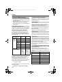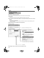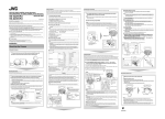
1
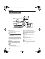
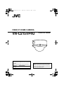
VN-C215VP_EN.book Page 1 Wednesday, December 20, 2006
4:26 PM
FIXED IP DOME CAMERA
VN-C215VP4U
START-UP GUIDE
For Customer Use:
Enter below the Serial No. which is located on
the body.
Retain this information for future reference.
VN-C215VP4U
Model No.
Serial No.
Thank you for purchasing this JVC product.
Before beginning to operate this unit,please
read the instructions carefully to ensure the
best possible performance.
LST0530-001A
VN-C215VP_EN.book Page 2 Wednesday, December 20, 2006
4:26 PM
Introduction
Safety Precautions
FOR USA
These are general IMPORTANT SAFEGUARDS and certain items may not apply to
all appliances.
IMPORTANT SAFEGUARDS
Read all of these instructions.
Save these instructions for later use.
All warnings on the product and in the operating instructions should be adhered to.
Unplug this appliance system from the wall outlet before cleaning. Do not use liquid cleaners or
aerosol cleaners. Use a damp cloth for cleaning.
5. Do not use attachments not recommended by the appliance manufacturer as they may cause hazards.
6. Do not use this appliance near water - for example, near a bathtub, washbowl, kitchen sink, or
laundry tub, in a wet basement, or near a swimming pool, etc.
7. Do not place this appliance on an unstable cart, stand, or table. The appliance may PORTABLE CART WARNING
fall, causing serious injury to a child or adult, and serious damage to the appliance. (symbol provided by RETAC)
Use only with a cart or stand recommended by the manufacturer, or sold with the
appliance. Wall or shelf mounting should follow the manufacturer's instructions,
and should use a mounting kit approved by the manufacturer. An appliance and
cart combination should be moved with care.
Quick stops, excessive force, and uneven surfaces may cause the appliance and
cart combination to overturn.
8. Slots and openings in the cabinet and the back or bottom are pro-vided for
S3125A
ventilation, and to insure reliable operation of the appliance and to protect it from
overheating, these openings must not be blocked or covered. The openings
should never be blocked by placing the appliance on a bed, sofa, rug, or other similar surface.
This appliance should never be placed near or over a radiator or heat register. This appliance should
not be placed in a built-in installation such as a bookcase unless proper ventilation is provided.
9. This appliance should be operated only from the type of power source indicated on the marking label.
If you are not sure of the type of power supplied to your home, consult your dealer or local power
company. For appliance designed to operate from battery power, refer to the operating instructions.
10.For added protection for this product during a lightning storm, or when it is left unattended and
unused for long periods of time, unplug it form the wall outlet and disconnect the antenna or cable
system. This will prevent damage to the product due to lightning and power-line surges.
11.Do not allow anything to rest on the power cord. Do not locate this appliance where the cord will be
abused by persons walking on it.
12.Follow all warnings and instructions marked on the appliance.
13.Do not overload wall outlets and extension cords as this can result in fire or electric shock.
14.Never push objects of any kind into this appliance through cabinet slots as they may touch
dangerous voltage points or short out parts that could result in a fire or electric shock. Never spill
liquid of any kind on the appliance.
15.Do not attempt to service this appliance yourself as opening or removing covers may expose you to
dangerous voltage or other hazards. Refer all servicing to qualified service personnel.
16.Unplug this appliance from the wall outlet and refer servicing to qualified service personnel under
the following conditions:
1.
2.
3.
4.
a.
b.
c.
d.
When the power cord or plug is damaged or frayed.
If liquid has been spilled into the appliance.
If the appliance has been exposed to rain or water.
If the appliance does not operate normally by following the operating instructions. Adjust only those controls
that are covered by the operating instructions as improper adjustment of other controls may result in damage
and will often require extensive work by a qualified technician to restore the appliance to normal operation.
e. If the appliance has been dropped or the cabinet has been damaged.
f. When the appliance exhibits a distinct change in performance - this indicates a need for service.
17.When replacement parts are required, be sure the service technician has used replacement parts
specified by the manufacturer that have the same characteristics as the original part. Unauthorized
substitutions may result in fire, electric shock, or other hazards.
18.Upon completion of any service or repairs to this appliance, ask the service technician to perform
routine safety checks to determine that the appliance is in safe operating condition.
2
VN-C215VP_EN.book Page 3 Wednesday, December 20, 2006
FOR USA AND CANADA
CAUTION
RISK OF ELECTRIC SHOCK
DO NOT OPEN
CAUTION :
TO REDUCE THE RISK OF
ELECTRIC SHOCK. DO NOT
REMOVE COVER (OR BACK). NO
USER-SERVICEABLE
PARTSINSIDE.REFER SERVICING
TO QUALIFIED SERVICE
PERSONNEL.
The lightning flash wish arrowhead
symbol, within an equilateral triangle is
intended to alert the user to the presence of uninsulated "dangerous voltage" within the product's enclosure that
may be of sufficient magnitude to constitute a risk of electric shock to persons.
The exclamation point within an equilateral triangle is intended to alert the
user to the presence of important operating and maintenance (servicing)
instructions in the literature accompanying the appliance.
INFORMATION (FOR CANADA)
RENSEIGNEMENT (POUR CANADA)
4:26 PM
Information for USA
This device complies with part 15 of the FCC Rules.
Changes or modifications not approved by JVC could
void the user's authority to operate the equipment.
This equipment has been tested and found to comply
with the limits for a Class A digital device, pursuant
to Part 15 of the FCC Rules. These limits are
designed to provide reasonable protection against
harmful interference when the equipment is operated
in a commercial environment. This equipment
generates, uses, and can radiate radio frequency
energy and, if not installed and used in accordance
with the instruction manual, may cause harmful
interference to radio communications. Operation of
this equipment in a residential area is likely to cause
harmful interference in which case the user will be
required to correct the interference at his own
expense.
This device complies with Part 15 of the FCC Rules.
Operation is subject to the following two conditions:
(1)This device may not cause harmful interference,
and (2) this device must accept any interference
received, including interference that may cause
undesired operation.
Due to design modifications, data given in this
instruction book are subject to possible change
without prior notice.
This Class A digital apparatus complies with
Canadian ICES-003.
Cet appareil num rique de la Classe A est
WARNING (FOR EUROPE):
This is a Class A product. In a domestic environment
this product may cause radio interference in which
case the user may be required to take adequate
measures.
3
VN-C215VP_EN.book Page 4 Wednesday, December 20, 2006
4:26 PM
Introduction
Safety Precautions
(continued)
Information for Users on Disposal of Old Equipment
[European Union]
This symbol indicates that the electrical and electronic equipment should not be
disposed as general household waste at its end-of-life. Instead, the product
should be handed over to the applicable collection point for the recycling of
electrical and electronic equipment for proper treatment, recovery and recycling
in accordance with your national legislation.
By disposing of this product correctly, you will help to conserve natural resources
and will help prevent potential negative effects on the environment and human
health which could otherwise be caused by inappropriate waste handling of this
product. For more information about collection point and recycling of this product,
please contact your local municipal office, your household waste disposal service
or the shop where you purchased the product.
Attention:
This symbol is
only valid in
the European
Union.
Penalties may be applicable for incorrect disposal of this waste, in accordance
with national legislation.
(Business users)
If you wish to dispose of this product, please visit our web page
www.jvc-europe.com to obtain information about the take-back of the product.
[Other Countries outside the European Union]
If you wish to dispose of this product, please do so in accordance with
applicable national legislation or other rules in your country for the treatment of
old electrical and electronic equipment.
Dear Customer,
This apparatus is in conformance with the valid
European directives and standards regarding
electromagnetic compatibility and electrical safety.
European representative of Victor Company of
Japan Limited.is:
JVC Technology Centre Europe GmbH
P.O.Box 10 05 52
61145 Friedberg
Germany
4
Sehr geehrter Kunde, sehr geehrte
Kundin,
dieses Gerät stimmt mit den gültigen europäischen
Richtlinien und
Normen bezüglich elektromagnetischer
Verträglichkeit und elektrischer
Sicherheit überein.
Die europäische Vertretung für die Victor Company
of Japan, Limited ist:
JVC Technology Centre Europe GmbH
Postfach 100552
61145 Friedberg
Deutschland
VN-C215VP_EN.book Page 5 Wednesday, December 20, 2006
䢇 The unit is to be powered by a DC 12 V
power supply.
䢇 The unit is to be powered by a UL Listed
DC12 V power supply. (For U type)
䢇 The 12 V DC power supply shall conform to
the following: Class 2 only (For USA),
Isolated power supply only (For Europe).
䢇 This installation should be made by a
qualified service person and should conform
to all local codes.
䢇 This installation shall be in accordance with
the National Electrical Code, ANSI/NFPA 70.
4:26 PM
This START-UP GUIDE basic usage of VNC215VP4U.
For detailed usage of VN-C215VP4U,
please refer to AINSTRUCTIONSB.
For latest information, please refer to
AReadmeB file in the supplied CD-ROM.
● The supplied CD-ROM includes
[INSTRUCTIONS (this manual)] (pdf), [API
Guide] (pdf) and [Search Tool].
● To view file in pdf format, the installation of
AAdobe ReaderBon the Computer is required.
䢇 Any Mention in this manual of Alarm inputs
have not been evaluated by UL to be used for
Burglar Alarm Functionality.
䢇 Special technique is required when installing
this product. Please refer to your dealer for
installation.
䢇 Rating label is pasted at the bottom of the
camera.
䢇 JVC is not liable for any compensation if you
drop the camera due to insecure mounting by
not following the installation description. Pay
careful attention during installation.
䢇 When mounting this product to a ceiling or
wall, select a location strong enough to
support the weight of this camera. If the
location is not strong enough to support the
weight, be sure to reinforce the ceiling or wall
before installation.
䢇 The camera may drop if the mounting screws
or pipings are not tightened securely. Check
that the screws are tightened appropriately
and securely.
䢇 Do not install the camera near lighting
fixtures of high temperature, such as spot
lights. It might result in failure or fires.
● Before starting an important recording, be
sure to perform a test recording in order to
confirm that a normal recording is possible.
● We do not accept liability for the loss of a
recording in the case of it becoming
impossible to record due to a problem in
the video camera, VTR, hard disk recorder
or video tape.
● Make sure you touch the metal surface of
the [MONITOR] terminal to release the
static electricity in your body before
adjusting the camera shooting direction.
5
VN-C215VP_EN.book Page 6 Wednesday, December 20, 2006
4:26 PM
Introduction
Main Features
䡵 High anti-dust and waterproof
performance
The anti-dust and waterproof mechanism allows
outdoor installation as the camera is not affected
by rain.
(IP66 specifications)
䡵 High Picture Quality
The camera unit employs a 380,000-pixel CCD
(1/4") which enables high quality image
monitoring.
䡵 Wide shooting range
䡵 Motion Detection Feature
This feature enables output of an alarm upon
detection of motion in the image within a preset
area.
Pre-recorded/post-recorded image files can be
sent via FTP using the alarm input.
䡵 Built-in Viewer
Monitoring via a computer is possible by
downloading the built-in viewer onto the
computer.
䡵 HTTP-based API
This product comes with a HTTP-based API.
This feature enables setting and control via the
network.
The adjustment range of the shooting direction is
wide and the camera can be mounted on a wall
with the use of a rotation adjustment
mechanism.
䡵 Unblocked Design
The dome-shaped design enables ease of use
without being blocked by the camera.
䡵 High-power varifocal lens
The built-in varifocal lens (optical zoom 3.6x)
makes detailed surveillance possible.
䡵 Night surveillance
This product comes with a low luminance feature
(Easy Day and Night), which switches
automatically to the high sensitivity mode (blackand-white) under low illumination.
䡵 Support for PoE (Power over Ethernet)
How to view this manual
䡵 Symbols used
Note
: Describes items concerning the
operation of this product.
Memo
: Describes reference information,
such as functions and usage
restrictions of this product.
A
: Indicates the reference page
numbers and reference items.
This product supports PoE (IEEE802.3af) and
enables power supply from a LAN cable.
䡵 Realization of Full Frame Rate
Data transmission is possible in VGA size at a
rate of 30 fps.
䡵 Built-in Web Server
Setting is possible using the Internet Explorer.
䡵 Support for Multicast
This product supports multicast, which enables
transmission of an image data to multiple
computers on the network without lowering the
frame rate.
6
䡵 About the contents of this manual
● All rights reserved by JVC. Unauthorized
duplication or reprinting of this manual, in
whole or in part, is strictly prohibited.
● Windows is a registered trademark of
Microsoft Corporation in the U.S.
● All other product names used in this
manual are trademarks or registered
trademarks of their respective companies.
Note that marks such as 姠, 姞 and 姝 have
been omitted in this manual.
● Illustrated designs, specifications and other
contents of this manual are subject to
change for improvement without prior
notice.
VN-C215VP_EN.book Page 7 Wednesday, December 20, 2006
Contents
Introduction
Safety Precautions ............................. 2
Main Features ..................................... 6
Contents ............................................. 7
Operating Environment ....................... 8
Cautionary Notes ................................ 8
Name and Function of Parts ............. 10
Features ........................................... 14
Setup
Procedures ....................................... 16
Removing the dome cover ................ 17
Mounting the base ............................ 17
Cable connection .............................. 18
Mounting the camera ........................ 19
Mounting the camera
via electrical box ........................ 21
Mounting the camera via piping ........ 22
Power Connection ............................ 24
Base GND cable connection ............ 25
Heater cable connection ................... 26
LAN Cable Connection ..................... 26
Alarm Input/Output
Cable Connection ...................... 27
Adjusting Images .............................. 28
Mounting the inner dome .................. 30
Mounting the dome cover ................. 30
4:26 PM
Setting
Network Requirements ..................... 32
IP Address Settings .......................... 33
● For Setting Using Internet Explorer,
please refer to the[INSTRUCTIONS]
(pdf) in the supplied CD-ROM.
Operation
Operation of Built-in Viewer .............. 39
Setting Up the Internet Explorer .... 40
Installing the built-in viewer ........... 42
Screen Configuration of Built-in
Viewer ..................................... 43
Quitting the Built-in Viewer ............ 44
Shortcut for Built-in Viewer ............ 44
Others
Specifications .................................... 45
7
VN-C215VP_EN.book Page 8 Wednesday, December 20, 2006
4:26 PM
Introduction
Operating Environment
䡵 PC Specification Requirements
OS
: Windows XP (Professional or
Home Edition) (SP2)
CPU
: Pentium4 1.5 GHz (or higher)
Memory
: 1 GB and above
Hard disk space : Free space of 20 MB and
above
Video Card
: 1024⳯768 pixels or higher,
True Color (24 or 32 bits)
Web browser
: Internet Explorer Version 6.0
䡵 LAN Environment
● 10BASE-T/100BASE-TX(PoE) network
interconnected using an IEEE802.3compliant switching hub.
● IEEE802.3af-compliant switching hub when
PoE is in use.
● IGMPv2-compliant network when multicast is
in use.
Memo:
● The above PC specifications are merely
guides for smooth use of the applications,
and not a guarantee of their operation.
● Depending on the condition of use,
applications may not run smoothly even when
the user’s computer meets the specification
requirements.
Cautionary Notes
Maintenance and operating
environment
䢇 Do not store in the following environments.
It might result in malfunctions or failure.
● Hot or cold locations beyond the
surrounding temperature range of -10I to
50I.
● Locations beyond the allowable operating
humidity range of 35%RH to 85%RH.
(condensation is not allowed)
● Near equipment that produces strong
magnetic fields, such as transformers or
motors.
● Near equipment that emits radio waves,
such as transceivers and mobile phones.
● Locations with excessive dust and sand.
● Locations that are subject to excessive
vibration.
● Locations prone to moisture such as window
side.
● Locations subject to steam or oil, such as
kitchens.
● Locations that emit radiation, X-rays or
corrosive gases.
䢇 Use of this product and cables connected to
this product at locations where strong electric
waves and magnetic waves are generated
(e.g., near radio, TV, transformer, motor, etc.)
may cause noise interferences in the images
or changes in the color.
䢇 Do not install at locations where cold air is
circulated, such as near the air vent of an air
conditioner.The drastic change in
temperature may fog up the dome cover.
䢇 Do not install at locations that may trap heat.
This product also discharges heat from the
surface. As such, do not install it at locations
that may trap heat, such as wall corners.
䢇 Compliance to IP66 standards does not
guarantee that the product is free from water
seepage under any environment.
Handling of Equipment
䢇 Do not block vents around the equipment.
Inadequate heat ventilation may result in
malfunction of this product. Be sure not to block
vents around the product.
8
VN-C215VP_EN.book Page 9 Wednesday, December 20, 2006
Others
䢇 This product has a built-in AGC circuit. When
AGC is AOnB, the product sensitivity
increases automatically at dark places and
the image on the screen may appear grainy.
This is not a malfunction.
䢇 When White Balance is set to AAutoB, the
principle of automatic tracking white balance
circuit may cause the color of the image to be
different from the actual color of the object,
depending on the condition of the object.
However, this is not a malfunction.
䢇 If a high-intensity object (such as a lamp) is
shot, vertical lines may appear on the image
(smear phenomenon) or blurring may occur
around the high-intensity object (blooming
phenomenon). This is a CCD characteristic
and is not a malfunction.
䢇 The electronic shutter of this product is set to
1/60 by default. To prevent flickering under
fluorescent lighting (except inverter
illumination) in a location with commercial
power frequency of 50 Hz, switch the shutter
speed to 1/100. (The sensitivity decreases a
little when the shutter speed is 1/100.)
䢇 When Easy Day and Night is set to AOnB, the
image becomes black and white in dark
locations. As the sensitivity is increased at
this time, the screen may appear grainy and
white spots may also increase. In addition,
when color images are changed to black and
white, bright areas of the screen are
emphasized and they may be difficult to see.
However, this is not a malfunction.
4:26 PM
䢇 To prevent fogging caused by temperature
changes, be sure to put the supplied silica gel
at the specified location. (A Pg. 20)
䢇 When multicast is in use, use the IGMPv2compliant network switch.
䢇 Electricity can be supplied to this product
either by using the PoE or connecting to the
DC12 V power supply. Make sure to select
only one mode of electrical supply.
Connecting the power cable and the LAN
cable for the PoE at the same time may result
in failure or malfunction of the camera.
(A Pg. 24)(A Pg. 25)
Copyrights of video
䢇 With the exception of the user being the
copyright holder or when permission has
been granted concerning duplication, etc. by
the copyright holder, permission is required in
principle for the duplication, modification,
transmission, etc. of copyrighted video/audio.
Unauthorized duplication, modification,
transmission, etc. of copyrighted material
may constitute a copyright infringement and
the user may be liable to compensate for any
damages. When using copyrighted video/
audio, be sure to check thoroughly the
license agreement, etc. of the copyrighted
material.
When there are rights or rights holders of the
duplicating subject, permission may be
required for shooting or using (processing) it.
Be sure to check thoroughly the licensing
conditions.
䢇 The image may be distorted or be mixed with
noises when the power voltage is cut off
instantaneously or is lowered by a lightning
strike or by switching on an air conditioner.
Maintenance
䢇 When this product is moved from a cold place
to a warm room, condensation may occur
and the product may not operate properly. In
this case, leave it for an hour under room
temperature before turning on the power.
䢇 Wipe off dirt on the dome cover with a lenscleaning cloth or a soft cloth. Wiping with
thinner or benzene may dissolve or tarnish its
surface. For dirt that cannot be easily
removed, wipe using a neutral detergent
diluted with water, followed by wiping with a
dry cloth.
䢇 The rotation angle of this product is set to
wide angle to support wide range equipment.
When the lens zoom is wide and the tilt angle
is approximately ±70⬚, the rotation angle may
cause part of the product to be reflected in
the image.
In this case, adjust the field angle if required.
(A Pg. 28)
䢇 Be sure to turn off the power before
performing maintenance.
Saving Energy
䢇 When not in use for a long period, turn off the
power of the system to prevent risk and to
reduce power consumption.
9
VN-C215VP_EN.book Page 10 Wednesday, December 20, 2006
4:26 PM
Introduction
Name and Function of Parts
Camera unit
K
J
A
I
B
H
G
C
D
E
F
A Mounting hole ⳯ 2
D Piping hole plug/Piping hole (side)
Use these when mounting the base to the
ceiling, wall or electrical box.
(A Pg. 17)(A Pg. 21)
This is used to mount the camera directly on the
piping from the side. A piping hole plug is
attached to this hole by default. (A Pg. 23)
Note:
E Dome cover
● To mount the camera using an electrical box,
please check with your dealer or nearest JVC
servicing center.
B Holes for connection cable and piping
This hole is for pulling out the connection cable.
You can also use this hole to mount the camera
directly on the piping. (Piping hole: G3/414UNC)
(A Pg. 22)
C Fall-prevention wire mounting screw
This is used to mount the fall-prevention wire to
the camera. (The fall-prevention wire is not
supplied.)
Note:
● Connect the fall-prevention wire to prevent
the camera from dropping.
10
The dome cover is fragile. Take care when
handling it.
F Inner dome
Before mounting the camera, remove it and
perform image angle setting.
(A Pg. 17)
G Dome cover fastening screw
These are fastening screws for the dome cover.
H Base
Mount the base to the ceiling, wall or electrical
box before mounting the camera.
(A Pg. 17)(A Pg. 21)
VN-C215VP_EN.book Page 11 Wednesday, December 20, 2006
4:26 PM
I Power cable for heater (AC 24 V)
(Gray, White)
Note:
● When installing a heater (sold separately:
KA-ZH215) to this product, be sure to
connect to AC 24 V.
● The AC 24 V power supply should conform to
the following : Class 2 only (For USA),
Isolated power supply only (For Europe).
● Please consult your nearest JVC dealer
regarding heaters.
J Base GND cable (Purple)
(A Pg. 25)
K Power supply/Alarm signal cable
(A Pg. 24)(A Pg. 27)
Signal name
Cable color
Alarm input 1
Pink
Alarm input 2
Blue
Alarm output 1
Orange
Alarm output 2
Yellow
GND
Brown
DC 12 V power supply+
Red
DC 12 V power supply-
Black
Note:
● Do not use PoE together with DC 12 V power
supply. Simultaneous connection will cause
failure or malfunction.
11
VN-C215VP_EN.book Page 12 Wednesday, December 20, 2006
4:26 PM
Introduction
Name and Function of Parts
(continued)
Inside the camera
L
Lens section
(A Next page)
M
N
O
P
Q
R
S
b
a
Z
Y
MAC address
X
T
U
W
V
L [10BASE-T/100BASE-TX(PoE)]
10BASE-T/100BASE-TX terminal
This is a 10BASE-T/100BASE-TX terminal.
It connects to the network via LAN cable.
(A Pg. 26)
M Rotation Knob
This knob rotates the lens section and adjusts
the tilting of the image. (A Pg. 28)
N Rotation center mark
(A Pg. 28)
O Fall-prevention wire
It connects the base H to the dome cover E.
P Camera Fastening Screw ⳯2
This secures the camera unit T and the base H.
How to remove (A Pg. 17)
12
Q [RESET] Reset button
This is a button for rebooting the camera. Press
this button and release within 5 seconds to
reboot the camera. It takes about 1 minute for
the camera to reboot. During startup, [RESET]
button is disabled.
Note:
● Pressing the [RESET] button for 5 seconds or
longer switches the camera to the service
verification mode. Do not press the button for
5 seconds or longer.
R Status indicator
This indicator appears blinking when the power
is turned on and turns off when the camera
startup is completed. Check the camera or the
connected device if the indicator remains
blinking when the camera is in use.
VN-C215VP_EN.book Page 13 Wednesday, December 20, 2006
S [MONITOR] Monitor terminal (RCA pin)
(A Pg. 28)
T Heater power connector
This power connector is used when the camera
is installed with a heater (sold separately: KAZH215).
4:26 PM
Lens section
SPOT
c
U Heater space
FOCUS ADJ
IRIS ADJ
Memo:
● When mounting the heater (sold separately
:KA-ZH215), read the instruction manual of
the heater carefully before mounting.
FOR SERVICE
d
V Camera unit
L
IRIS
LEVEL
H
e
f
W Camera Fastening Claw ⳯2
This claw fastens the camera unit to the base. To
remove the base, push it towards the direction of
the arrow and remove. (A Pg. 17)
X [MAC address] MAC address indicator
The MAC address is a unique physical address
of the product. This address cannot be altered.
Y Tilt fastening screw
After adjusting the field angle, tighten the screw
so that the camera field angle will not be
misaligned when using the camera in locations
with vigorous vibrations. (A Pg. 28)
Z Imaging Direction mark
Install the camera facing the arrow in the
shooting direction.
a Lug plate
This plate fastens the silica gel.
(A Pg. 20)
b Silica gel insertion space
(A Pg. 20)
c [FOCUS ADJ] Focus adjustment button
This is used to adjust the lens focus.
Press the button to open the lens iris for 30
seconds. The focus is now easier to adjust as
the depth of field becomes shallow. (A Pg. 29)
Memo:
● Pressing the focus adjustment button
automatically activates the electronic shutter. The
screen may flicker but this is not a malfunction.
d [IRIS LEVEL] Iris level adjustment dial
This dial adjusts the iris level of the auto iris lens.
Normally, adjustment is not required. Adjust if
required, depending on the conditions of the object.
To darken: Anti-clockwise direction (towards L)
To brighten: Clockwise direction (towards H)
Memo:
● Adjust the iris level after [AGC] is set to AOffB.
For AAGC function settingsB, please refer to
the [INSTRUCTIONS](pdf) in the supplied CDROM.
● If AOffB is not set, turning the dial towards L
will activate the AGC function. The camera
sensitivity increases and the image quality
becomes grainy.
e Focus adjustment ring
Move the ring to the left and right to adjust the focus.
(A Pg. 29)
f Zoom adjustment ring
Move the ring to the left and right to adjust the field angle.
(A Pg. 29)
13
VN-C215VP_EN.book Page 14 Wednesday, December 20, 2006
4:26 PM
Introduction
Features
Saving JPEG images to the FTP server
at regular intervals
Monitoring Via Built-in Viewer
VN-C215VP4U comes with a built-in ActiveX
viewer.
Monitoring of VN-C215VP4U images using the
computer is possible by installing this built-in
viewer on the computer. Images that are
currently displayed may also be captured in the
computer’s hard disk.
AOperation of Built-in ViewerB (A Pg. 39)
JPEG images may be uploaded to the FTP
server at regular intervals.
VN-C215VP4U
Network
VN-C215VP4U
Computer
Sending latest
images to FTP
regularly
Alarm
Network
Computer
Monitoring Via Multicast
Monitoring using multiple computers is possible
via multicast.
VN-C215VP4U comes with a motion detection
feature and dual alarm input.
By motion detection or alarm input, action such
as mail delivery, message transmission via TCP/
UDP, alarm output can be triggered.
Combination of alarm inputs can be trigger.
Installing an FTP server enables uploading of
images before and after the alarm input time
(pre-/post-recording) to the server.
VN-C215VP4U
VN-C215VP4U
Alarm Device
Computer
IGMPv2
compliant
Network
Network
Computer
Computer
14
Sending images
before and after
alarm input
Computer
VN-C215VP_EN.book Page 15 Wednesday, December 20, 2006
4:26 PM
Restrictions on Clients
It is possible for VN-C215VP4U to permit or deny
image acquisition of designated IP addresses.
Control via customized application
software
The following uses are also possible by
developing a customized application software
that supports the API of VN-C215VP4U.
For details, please refer to the [API Guide] in the
attached CD-ROM.
● Monitoring via the computer while at the
same time recording images to the HDD.
● Recording by changing the frame size/frame
rate during alarm occurrence.
● Recording the type and time of alarm occurrence
to the computer.
● For detailed usage of VN-C215VP4U ,
please refer to [INSTRUCTIONS] (pdf) in
the supplied CD-ROM.
15
VN-C215VP_EN.book Page 16 Wednesday, December 20, 2006
4:26 PM
Setup
Procedures
The connection and setup procedures are
described as below.
䢇 Make sure you touch the metal surface of
the [MONITOR] terminal to release the
static electricity from your body. Static
electricity may cause the camera to
malfunction.
䢇 Make sure that various parts of the camera
do not drop on the floor when mounting the
base to the ceiling or connecting the cable
of the camera unit.
䢇 When mounting the heater (sold separately
: KA-ZH215), read the instruction manual of
the heater carefully before mounting.
Setup (A Pg. 16)
step 1
Mount the camera and configure
image settings.
K
Network Settings
(A Pg. 32)
step 2
Configure the network settings of
the computer and this camera.
K
Internet Explorer Settings
step 3
T For details, please refer to the
[INSTRUCTIONS](pdf) in the
supplied CD-ROM.
K
Operation of Built-in Viewer
(A Pg. 39)
step 4
16
Monitoring and still image saving
operations are possible using the
built-in viewer.
VN-C215VP_EN.book Page 17 Wednesday, December 20, 2006
Removing the dome cover
1. Remove the dome cover
Loosen the dome cover fastening screws (x3)
with the wrench (supplied) and remove the dome
cover.
Memo:
● The dome cover is connected to the base via
a fall-prevention wire.
4:26 PM
Mounting the base
Remove the camera unit from the base and
mount the base to the ceiling or wall.
To mount on a wall, use the same procedures
below but replace the word “ceiling” with “wall”.
Setup
If necessary, use the attached template to drill
a hole (R30 mm, 1-1/8 inches) for mounting.
R30 mm
(1-1/8 inches)
Wrench (Supplied)
Fall-prevention wire
(not attached)
Approx. 100 mm
(3-7/8 inches)
Power cable,
alarm cable,
heater cable
Fall-prevention
wire
LAN cable
1. Remove the camera unit from the base
2. Remove the inner dome
The inner dome is secured by 3 claws. Remove
the inner dome from the claws.
Note:
● Make sure you touch the metal surface of the
[MONITOR] terminal to release the static
electricity from your body. Static electricity
may cause the camera to malfunction.
A Loosen the camera fastening screws (x2)
with the screw driver.
B Remove the camera from the base while
pressing in the two claws.
A
B
Claw
(2 locations)
Inner
dome
Camera unit
Base
Claw
(3 locations)
17
VN-C215VP_EN.book Page 18 Wednesday, December 20, 2006
4:26 PM
Setup
Mounting the base (continued)
2. Mount the fall-prevention wire to the base
(The fall-prevention wire is not attached)
Remove the fall-prevention wire mounting screw
of the base and mount the fall-prevention wire.
Cable connection
1. Connect the LAN cable (A Pg. 26)
2. Connect the power cable, alarm cable and
heater cable
(A Pg. 24)(A Pg. 26)(A Pg. 27)
Memo:
Note:
● Also pay careful attention to the length,
strength, wiring and material (insulation
quality) of the fall-prevention wire to be used.
● For the fall-prevention wire, the inside
diameter of the ring section to be mounted on
the camera unit should be between R4.1 mm
and R6.5 mm, and the outside diameter
should be below R12 mm.
3. Mount the fall-prevention wire to a strong
● The power cable must not be connected
when PoE is used.
● When the camera is installed with a heater
(sold separately: KA-ZH215), be sure to
connect it to AC 24 V power supply.
● The AC 24 V power supply should conform to
the following : Class 2 only (For USA),
Isolated power supply only (For Europe).
3. Wind the waterproof tape
location.
Mount the fall-prevention wire to a strong
location to prevent fall.
4. Mounting the base
Face the imaging direction mark inside the base
(j) in the shooting direction and mount the base.
When mounting to a wall, face the imaging
direction mark (j) upwards.
Use two R4 mm screws for mounting.
Power cable, alarm
cable
2
LAN cable
Note:
● When mounting to a wall, be sure to face the
imaging direction mark (j) upwards.
● R4 mm screws are not supplied. Use the
appropriate type according to the material of
the location for mounting.
● The two attached screws (M4 ⳯8 mm) are
for mounting the base to the adapter plate.
Do not use them here.
3
Base
Wind the
waterproof tape
3
Wind the insulation tape
1
10BASE-T/
100BASETX(PoE)
terminal
Fall-prevention
wire
8 mm
Solder or crimp
2
LAN cable
2 mm
Note:
Towards the shooting
direction
(Face upwards when
mounting to wall)
18
4
R4 mm screw
● Be careful not to drop the camera when it is
removed from the base.
VN-C215VP_EN.book Page 19 Wednesday, December 20, 2006
4:26 PM
2. Mount the camera to the base
Mounting the camera
Fill up the piping hole and mounting hole with
sealant, mount the camera to the base and
insert silica gel.
1. Fill up the holes with sealant
Use sealant to fill up the mounting holes (x2) to
which the piping hole and screws are mounted.
Push in the two claws until you hear a click
sound.
Note:
● Mount the camera such that the cables and
fall-prevention wire of the dome cover are not
caught in between.
3. Secure the camera with the camera
fastening screws (x2).
Tighten the camera fastening screws (x2) with
the screw driver and secure the camera.
2
Sealant
Claw
(2 locations)
Memo:
● Use GE silicon or other equivalent for the
sealant.
Note:
3
● If the mounting holes (x2) are not completely
sealed up with sealant, water or moisture
may seep in and fog up the lens and dome
cover. Seal up these holes completely.
19
VN-C215VP_EN.book Page 20 Wednesday, December 20, 2006
Setup
Mounting the camera
(continued)
4. Insert the supplied silica gel
Take out the silica gel from its aluminum pack,
insert it in the space for silica gel inside the
camera and secure with a lug plate.
Space for inserting
silica gel
Silica gel
Lug plate
Memo:
● Be sure to replace the silica gel when you
reconnect or reinstall the camera during
repair or maintenance.
● For replacement, please consult your nearby
JVC’s dealer.
Use silica gel of service parts number
LW40500-001A for the parts to be replaced.
Note:
● Pay attention that rain does not seep into the
camera when mounting it during rainy days.
● Be sure to use the supplied silica gel. Failure
to do so may fog up the camera lens or dome
cover.
● If the field angle is not adjusted immediately
after mounting the camera, insert the silica
gel after adjustment. The silica gel will lose its
effect if it is exposed to air for a long time.
20
4:26 PM
VN-C215VP_EN.book Page 21 Wednesday, December 20, 2006
4:26 PM
Mounting the camera via
electrical box
Mount the base to an electrical box.
1. Remove the camera unit from the base
(A Pg. 17)
2. Mount the base to the electrical box
Use two mounting holes and two M4 screws to
mount the base to the electrical box.
Memo:
● M4 screws are not supplied.
4 inch square electrical box
M4 screw (not supplied)
3. The following procedures are the same as
normal mounting
● Cable connection (A Pg. 18)
● Mounting the camera to the base
(A Pg. 19)
● Image adjustment (A Pg. 28)
● Mounting the inner dome (A Pg. 30)
● Mounting the dome cover (A Pg. 30)
21
VN-C215VP_EN.book Page 22 Wednesday, December 20, 2006
4:26 PM
Setup
Mounting the camera via
piping
Seal tape
4
12 mm and below
Use a piping hole to mount the camera.
7
Use the piping hole at the bottom of the
base to mount the camera
Fall-prevention wire
5
1. Remove the camera unit from the base
(A Pg. 17)
2. Mount the fall-prevention wire to the base
3
8 mm
(A Pg. 18)
2 mm
3. Wind the seal tape
Wind the joint (where the threaded portion of the
piping hole and the tapped hole of the piping
meets) of the piping with seal tape for more than
2 rounds.
4. Mount the base to the piping
Turn the base in a clockwise direction and screw
into the piping. (Piping hole: G3/4-14 UNC)
Note:
● Do not screw in the piping for more than 12
mm deep. Otherwise, it may damage the
internal parts of the camera.
5. Secure the base to the ceiling
Use RM4 mm screws (x2) to secure the base
tightly to the ceiling.
● Check that there is no gap between the
ceiling and the base.
Note:
● RM4 screws are not supplied. Use the
appropriate type according to the material of
the location for mounting.
● The two attached screws (M4 ⳯8 mm) are
for mounting the base to the adapter plate.
Do not use them here.
AMounting the camera via electrical boxB
(A Pg. 21)
6. Mount the fall-prevention wire to a strong
location (A Pg. 18)
22
6
RM4 mm screw
7. The following procedures are the same as
normal mounting
● Cable connection (A Pg. 18)
● Mounting the camera to the base
(A Pg. 19)
● Image adjustment (A Pg. 28)
● Mounting the inner dome (A Pg. 30)
● Mounting the dome cover (A Pg. 30)
VN-C215VP_EN.book Page 23 Wednesday, December 20, 2006
Using the piping hole at the side of the
base to mount the camera
4:26 PM
4. Mount the piping hole plug to the piping
hole at the bottom of the base
5. Mount the base to the piping
When the camera is not directly mounted on a
ceiling, use the piping hole at the side of the
base to mount the camera to the piping.
Screw the piping into the piping hole at the side
of the base.
(Piping hole: G3/4-14 UNC)
1. Remove the camera unit from the base
Note:
and mount the fall-prevention wire
(A Pg. 17)(A Pg. 18)
2. Wind the seal tape
Wind the joint (where the threaded portion of the
piping hole and the tapped hole of the piping
meets) of the piping with seal tape for more than
2 rounds.
● Do not screw in the piping for more than 12
mm deep. Otherwise, it may damage the
internal parts of the camera.
Piping hole
plug
Seal tape
3. Remove the piping hole plug of the base
Loosen the mounting screw (M3 x 6 mm) with a
straight slot screw driver and pull out the plug
from the side of the base.
Piping hole plug
6. The following procedures are the same as
normal mounting
● Cable connection (A Pg. 18)
● Mounting the camera to the base
(A Pg. 19)
● Image adjustment (A Pg. 28)
● Mounting the inner dome (A Pg. 30)
● Mounting the dome cover (A Pg. 30)
Mounting
screw
23
VN-C215VP_EN.book Page 24 Wednesday, December 20, 2006
4:26 PM
Setup
Power Connection
Connecting to the DC12 V power supply
Electricity can be supplied to this product either
by using the PoE or connecting to the DC 12 V
power supply.
Connect this product to the DC12 V power
supply when not using the PoE.
Connect the polarity correctly.
䢇 When electricity is supplied to the camera,
the status indicator blinks, and turns off when
startup is complete.
Red
: DC12 V+
Black
: DC12 V-
Note:
Note:
● Make sure to select only one mode of
electrical supply. Connecting the power cable
and the LAN cable for the PoE at the same
time may result in failure or malfunction of the
camera.
● Make sure to select only one mode of
electrical supply. Connecting the power cable
and the LAN cable for the PoE at the same
time may result in failure or malfunction of the
camera.
Using the PoE
Connect to a device that supports PoE and
supply electricity from the LAN cable.
Base
Power cable
What is PoE (Power over Ethernet)?
This is a function that enables operation of a
LAN equipment without a power cable by
supplying power simultaneously with the data
using a LAN cable.
Connect to PoEcompatible device
Black:
DC12 VLAN cable
Red:
DC12 V+
Solder or
crimp
Wind the
waterproof
tape
Insulation tape
Heater power cable
(White, Gray)
10BASE-T/
100BASETX(PoE)
terminal
LAN cable
Memo:
● For details on the connection method and
cable type, please refer to ALAN Cable
ConnectionB (A Pg. 26).
24
Memo:
About the power cable
● When using 2-core VVF (Vinyl-insulated
vinyl-sheath cable), the connection distance
is as follows: (Reference value)
Maximum
extension
90 m
(300 ft)
240 m
(790 ft)
390 m
(1280 ft)
Conductor
Diameter
(mm)
R1.0 and
above
R1.6 and
above
R2.0 and
above
VN-C215VP_EN.book Page 25 Wednesday, December 20, 2006
Warning
The rated power of this product is DC12 V.
Make sure to use it with the correct voltage.
Supplying a power different from the rated
value may result in failures and in the worst
scenario, smoking and fire.
4:26 PM
Base GND cable connection
To mount the camera to the base at a location
insulated from the ground, connect DC12 V(Black) cable with the base GND cable (Purple).
Memo:
● In a system where multiple units of VNC215VP4U are used, turn on the power of
only 1 unit to configure the IP address
settings via the Internet Explorer. Upon doing
so, turn on the power of the second unit and
configure accordingly. Configure the camera
settings using the same procedure.
● Whenever duplication of IP addresses
occurs, check that there is only one VNC215VP4U under the same LAN
environment and wait for at least 10 minutes.
Access to VN-C215VP4U may be denied
unless you restore the power supply of all
network devices under the same LAN
environment.
● To use AA-P700 in the power supply unit,
connect one unit of this product. Also refer to
the AA-P700 instruction manual.
Base
Base GND cable
(Purple)
Solder or crimp
Wind the waterproof tape
Insulation tape
DC12 V- cable
(Black)
25
VN-C215VP_EN.book Page 26 Wednesday, December 20, 2006
4:26 PM
Setup
Heater cable connection
LAN Cable Connection
Connect the camera to a hub or computer using
a LAN cable.
䡵 When connecting to a hub
Make use of a straight cable.
䡵 When connecting to a computer
Make use of a Cross Over cable.
AC24 V power supply
Solder or
crimp
Wind the
waterproof tape
Insulation tape
Heater power cable
(White, Gray)
10BASE-T/
100BASETX(PoE)
terminal
LAN cable
Note:
● When installing a heater unit (sold
separately: KA-ZH215) to this product, be
sure to connect to AC 24 V.
● When installing a heater unit (sold
separately: KA-ZH215), read the heater
instruction manual carefully before installing.
● The AC 24 V power supply should conform to
the following : Class 2 only (For USA),
Isolated power supply only (For Europe).
● Please consult your nearest JVC dealer
regarding heaters.
䢇 About heater cables
Maximum
extension
40 m
(130 ft)
120 m
(390 ft)
180 m
(590 ft)
Conductor
Diameter
(mm)
R1.0
R1.6
R2.0
26
Note:
● Cross cables cannot be used with some
computer models. When connecting VNC215VP4U directly to a computer, make sure
to check the computer’s LAN specifications in
advance.
Memo:
● Sealed cables are recommended for outdoor
use.
● Make use of a Category 5 (or higher) cable in
the case of 100BASE-TX.
VN-C215VP_EN.book Page 27 Wednesday, December 20, 2006
Alarm Input/Output Cable
Connection
Connect the alarm input/output cables with
external devices such as a sensor, buzzer, etc.
Signal name
Cable color
Alarm input 1
Pink
Alarm input 2
Blue
Alarm output 1
Orange
Alarm output 2
Yellow
GND
Brown
4:26 PM
Alarm Input
Connect this terminal to sensor devices, such as
an infrared sensor, door sensor, metal sensor,
manual switch, etc.
䡵 Input requirements
● No-voltage relay NPN open collector input
● Polarity of input detection can be selected
using a software
● Make/Break (500 ms and above)
● Circuit current at low level: 0.3 mA
● Applied voltage at high level: 3.3 V
Camera
unit
DC3.3 V
R
Cable to use
● Length of 50 m or shorter
● UL1007, UL1015 or equivalent products
● AWG#22 - AWG#18 or equivalent products
Sensor example (1)
Input 1
or Input 2
VCC
R
OUT
3.3 V
0.3 mA
GND
GND
(Alarm input equivalent circuit)
Sensor example (2)
Relay switch etc.
OUT
GND
Alarm input/output
cables
Alarm Output
Solder or crimp
LAN cable
Connect this terminal to annunciating devices, such
as annunciators, indicators, lights, buzzers, etc.
䡵 Output requirements
Wind the
waterproof
tape
3
Insulation tape
● Equivalent to NPN open collector output (Set
the output put logic via the Internet Explorer)
● Allowable applied voltage: DC12 V and below
● Allowable inflow current: 50 mA
● Momentary (100 ms to 5000 ms) output
(Set time via the Internet Explorer )
Example of
annunciating
devices
Camera
unit
Output 1
or Output 2
DC 12 V
IN
R
Note:
● Noises from an external source may cause
malfunctions even when the cable used is
shorter than 50 m. In this case, use a
shielded cable or move the cable away from
the noise source.
GND
GND
(Alarm output equivalent circuit)
Note:
● Connect the GND cable of this camera to the
GND of the annunciating device.
27
VN-C215VP_EN.book Page 28 Wednesday, December 20, 2006
4:26 PM
Setup
Adjusting Images
Pan: ±175 ⬚
When the camera is mounted, adjust the image
settings while looking at the actual image.
Mounting the test monitor
Connect the [MONITOR] terminal of the camera
to the test monitor to adjust the camera shooting
direction, field angle and focus.
T When configuring, turn on the power of the
camera.
Rotation: ±175 ⬚
Tilt: ±70 ⬚
[MONITOR]
terminal
Shooting direction mark
Pan center mark
Rotation center mark
SPOT
S ADJ
S ADJ
75 K terminated
CE
IRIS
EVEL
H
Rotation clasp
:Make sure you hold
and turn this clasp when
adjusting the rotation.
Memo:
Test monitor
Adjusting the camera shooting direction
This camera can be adjusted for pan, tilt and
rotation. Adjust the direction and face the
camera towards the object.
Note:
● Make sure you touch the metal surface of the
[MONITOR] terminal to release the static
electricity from your body. Static electricity
may cause the camera to malfunction.
28
● Rotate both pan and rotation ±175 ⬚ from the
positions aligned with the camera imaging
direction mark, pan center mark and rotation
center mark. Make sure you hold the rotation
knob and adjust the rotation without holding
the lens section.
● After adjusting the field angle, tighten and
secure the tilt fastening screw so that the field
angle will not be misaligned when using the
camera in locations with vigorous vibrations.
(A Pg. 12)
Note:
● Moving the camera when it has exceeded the
adjustment range may cause its performance
to deteriorate.
● As the tilt and rotation range of this camera is
wide, part of the camera may be reflected in
the shooting screen depending on the field
angle and direction.
● Do not hold the lens section when adjusting
the camera direction. The lens section may
be damaged if you apply force to it.
VN-C215VP_EN.book Page 29 Wednesday, December 20, 2006
Adjusting field angle, focus and
brightness
Once you have decided the shooting direction,
you can adjust the field angle, focus and
brightness.
Note:
● Be sure to hold the dome cover over the lens
when adjusting the focus. The dome cover is
made thicker for performance purposes. If
focus is not adjusted with the dome cover
held over the lens, the camera may be out of
focus when the dome cover is actually
attached.
● When adjusting focus, hold the dome cover
over the lens such that the optical axis of the
lens and the center of the dome cover is
perpendicular to each other and the image is
not distorted. (Refer to the diagram below)
4:26 PM
Field angle adjustment
Loosen the fastening screw of the zoom
adjustment ring, move the ring left and right and
adjust the image size.
Focus adjustment
Press the focus adjustment button. The Iris will
open for approximately 30 seconds. Loosen the
fastening screw of the focus adjustment ring,
move the ring left and right and adjust the focus.
Memo:
● Repeat “Field angle adjustment” and “Focus
adjustment” two to three times to adjust the
settings.
After adjustment is complete, tighten and
secure the respective fastening screws.
● Pressing the focus adjustment button
automatically activates the electronic shutter.
The screen may flicker but this is not a
malfunction.
Brightness adjustment
Normally, adjustment is not required. If
necessary, adjust the Iris level.
Op
ti
ca
xis
FOCUS ADJUST
IRIS
LEVEL
Iris level
adjustment dial
H
: Anti-clockwise direction
(towards L)
To brighten
: Clockwise direction (towards
H)
lA
Focus
adjustment button
L
To darken
Note:
● Do not adjust the iris level within 30 seconds
after pressing the focus adjustment button.
The electronic shutter will activate and you
will not be able to adjust correctly.
● When adjusting the iris level, set the [AGC]
function to AOffB. Otherwise, when the level is
turned too far toward L, the [AGC] function
activates, hence increasing sensitivity and
the picture may look grainy.
Zoom adjustment ring
W
T
Focus adjustment ring
N
F
29
VN-C215VP_EN.book Page 30 Wednesday, December 20, 2006
4:26 PM
Setup
Mounting the inner dome
Mounting the dome cover
After all settings are complete, mount the inner
dome to the camera.
1. Clean the dome cover
1. Mount the inner dome
Before mounting, remove and clean any dust or
dirt on the dome cover.
Mount the inner dome to the claws (x3).
Memo:
● Dirt on the dome cover may be reflected in
the images.
Note:
● Do not pull or apply excessive force to the
dome cover.
Claw
(3 locations)
2. Mount the dome cover to the base
Align the base with the position alignment marks
(x3) on the dome cover and mount the dome
cover.
3. Secure the dome cover
Inner
dome
Tighten the dome cover fastening screws (x3)
with wrench (supplied) and secure.
38
Position alignment marks
(3 locations)
Note:
● Mount the inner dome without covering the
lens.
● When mounting the inner dome, make sure
that the position of the lens is not shifted.
Otherwise, the configured field angle will be
distorted.
3
Wrench (Supplied)
30
2
VN-C215VP_EN.book Page 31 Wednesday, December 20, 2006
4:26 PM
Note:
● Secure the dome cover tightly. Insecure
mounting may increase humidity, fog up the
camera or the cover may drop.
● When the cover is removed again after
mounting the dome cover, adjust the field
angle.
● Make sure that the fall-prevention wire of the
dome cover is not caught between the dome
cover and the base. Otherwise, the anti-dust
and waterproof function may not work
properly.
31
VN-C215VP_EN.book Page 32 Wednesday, December 20, 2006
4:26 PM
Setting
Network Requirements
Insufficient network bandwidth
● Ensure that there is sufficient network
bandwidth for the data volume to be sent out
by VN-C215VP4U.
● Data volume to be sent by VN-C215VP4U varies
with the settings and number of distributions.
● The maximum bit rate from VN-C215VP4U is
about 9 Mbps.
When there is insufficient bandwidth, the number
of JPEG frames (frame rate) that the client can
acquire will decrease.
Estimation of total bit rate
The JPEG file size per frame varies with the encoding
settings as well as input video signals. The following
table may be used as a reference. When VFS is
selected, the quantization table during JPEG
encoding will be maintained and the file size will
increase/decrease according to the input signals.
When AFS is selected, encoding will be performed
such that the average size of multiple JPEG images is
the target file size.
Picture Quality
Control Method
VGA File
Size
QVGA File
Size
VFS
(Variable
File Size)
1 (High)
80 KB
27 KB
2
60 KB
20 KB
3
40 KB
13 KB
4
(Medium)
30 KB
10 KB
5
25 KB
8 KB
6
20 KB
7 KB
7 (Low)
15 KB
AFS
(Average File Size)
Selection
may be
made from
the range
between 10
and 100 KB
5 KB
Selection
may be
made from
the range
between 3
and 33 KB
VN-C215VP4U accepts requests from up to a
maximum of 5 clients. In addition, it also allows
transmission of 1 multicast stream. The total frame
rate refers to the sum of these frame rates.
For example, when 10 fps is requested by 2
clients, and in addition multicast is transmitted at
a rate of 10 fps, the total frame rate will be:
10 + 10 + 10 = 30 fps
If the JPEG file size per frame is 30 KB, then the
total bit rate will be:
30 KB x 30 fps = 900 KB/s = Approx. 7.2 Mbps
32
Network Delay
When the client acquires JPEG via TCP, VNC215VP4U will send out data while checking the
ACK from the client at the same time. For
networks with considerable delay, data cannot be
sent out until ACK is received, and therefore the
frame rate will drop.
Drop of frame rate due to network delay can be
eliminated by sending data via multicast.
Network Jitter
When there is considerable network jitter, delay time
may be prolonged and the image frame rate may drop.
Packet Loss
When acquiring images from VN-C215VP4U via
TCP, packet loss may be recovered by resending
by TCP. When there is considerable delay during
resending, however, missing data may occur and
the image frame rate may drop.
When packet loss occurs during multicast
sending from VN-C215VP4U, the image frame
rate may drop.
List of protocols and port numbers used
by VN-C215VP4U
VN-C215VP4U uses the protocols and port
numbers listed below. Ensure that these ports are
allowed through the firewall when a firewall is to be
installed.
Protocol/Port No.
Purpose of Use
TCP/80
JPEG acquisition, Web
Settings page, API
TCP/20, 21
FTP
TCP/25
Mail delivery
TCP/User Setting No.
Alarm sending
UDP/User Setting No.
Alarm sending
UDP/User Setting No.
Multicast sending
UDP /123
SNTP
VN-C215VP_EN.book Page 33 Wednesday, December 20, 2006
IP Address Settings
Setting IP address with the default VNC215VP4U settings
There are 2 methods to set the IP address when
VN-C215VP4U is in its default settings.
4:26 PM
䡵 (B) Assigning a static IP address
䢇 System configuration required for setting
IP address
VN-C215VP4U is set to ADHCP EnableB (the
DHCP client function is ON) by default. Start VNC215VP4U in LAN without DHCP server. After
DHCP timeout, VN-C215VP4U starts with the
following IP address.
(A) Assigning an IP address to VN-C215VP4U
from the DHCP server
IP address
Subnet mask
: 255.255.255.0
(B) Assigning a static IP address to VNC215VP4U
Default gateway
: None
䡵 (A) Assigning an IP address from the
DHCP server
● VN-C215VP4U is set to ADHCP EnableB (the
DHCP client function is ON) by default. To
assign an IP address from DHCP server,
connect VN-C215VP4U to LAN with DHCP
server, and turn on VN-C215VP4U. Allowing
the DHCP server to assign the same IP
address to VN-C215VP4U every time eases
access to VN-C215VP4U.
● For details on IP addresses assigned to VNC215VP4U, please consult your network
administrator.
● You can look up the IP address of VNC215VP4U using the [Search Tool] in the
attached CD-ROM.
For details, please refer to the AReadmeB file
in the attached CD-ROM.
Note:
● Set the DHCP server such that constant IP
address is assigned to VN-C215VP4U based
on the MAC address of VN-C215VP4U.
Access by clients can fail if the above setting
is not performed.
: 192.168.0.2
Memo:
● To set a static IP address for VN-C215VP4U,
connect VN-C215VP4U, switching hub and
computer for setting using a straight LAN
cable of Category 5 and above.
䢇 Set up the computer for setting the IP
address.
● Minimum computer specifications for
setting
OS
: Windows XP (Professional or
Home Edition) (SP2)
Web browser : Internet Explorer Version 6.0
Note:
● When setting the IP address for VNC215VP4U, do so by using a network that is
made up only of VN-C215VP4U, the
computer for setting and the switching hub.
● Using a hub connected to other network
devices can cause problems.
33
VN-C215VP_EN.book Page 34 Wednesday, December 20, 2006
4:26 PM
Setting
IP Address Settings
(continued)
䢇 IP Address setting at the computer
Set the computer to an IP address that enables communication with VN-C215VP4U.
1. Click [Start]
● Select in the order of [Control Panel]-[Network Connection]-[Local Area].
2. The computer with which Internet Explorer is launched automatically selects the connected
network
● Right-click and select [Properties].
● Check to ensure that the [Client for Microsoft Networks] and [Internet Protocol(TCP/IP)] check
boxes are selected.
3. Select [Internet Protocol(TCP/IP)] and click [Properties].
4. Set the IP address
A Select [Use the following IP adress].
B Set the [IP Address]. (For example, use
192.168.0.100 when VN-C215VP4U is in its
default settings)
Memo:
● Make sure that you take note of the
original IP address before altering.
Note:
● When setting, ensure that a duplicate IP
address is not used within the same
network environment.
C Set [Subnet Mask] to a value that is
appropriate for the setting operation. Clarify
with the network administrator if you have
any queries.
(Use 255.255.255.0 when the camera is in
its default settings)
D When a [Default Gateway] is present, make
use of the IP address (e.g., 192.168.0.254).
E Click [OK].
5. Click [OK] on the [Local Area Connection Properties] screen
34
VN-C215VP_EN.book Page 35 Wednesday, December 20, 2006
4:26 PM
䢇 Changing the IP address using the Internet Explorer
1. Launch the Internet Explorer on the computer
2. When proxy setting is enabled in the Internet Explorer, follow the steps below to disable the
proxy of the Internet Explorer
● Select in the order of [Tools]-[Internet Options...]-[Connections]-[LAN Setting], followed by
deselecting the check for [Use a proxy server for your LAN] in [Proxy Server] of the [Local Area
Network(LAN)Settings] window.
Deselect the check
3. If Active scripting of the Internet Explorer is not set to AEnableB, follow the steps below to enable it
● Select [Trusted sites] under [Tools]-[Internet Options...]-[Security]. Upon doing so, the [Sites...]
button directly below becomes active. Click on this button and deselect the check for [Require
server verification(https:) for all sites in this zone] in the displayed window. Next, add VNC215VP4U web site to the zone.
Example: http://192.168.0.2
● Next, select [Trusted sites] under [Tools]-[Internet Options...]-[Security], and press the [Custom
Level] button. Select [Enable] under [Scripting]-[Active scripting] of the [Security Settings]
window that has been opened.
Select [Enable]
35
VN-C215VP_EN.book Page 36 Wednesday, December 20, 2006
4:26 PM
Setting
IP Address Settings
(continued)
䢇 Changing the IP address using the Internet Explorer (continued)
4. Launch the Internet Explorer
A Enter the following IP address in the address field.
http://192.168.0.2
B Click [Go].
Memo:
● If the proxy server setting in Internet Explorer is enabled, you may not be able to specify the IP
address directly. In this case, change the proxy settings of the Internet Explorer.
● After the Security Warning screen appears, press the [OK] button to proceed.
5. Enter the user name and password (login as an administrator)
VN-C215
A Enter the user name.
This is set to AadminB by default.
B Enter the password.
This is set to Avn-c215B by default.
C Click [OK].
Memo:
● After the Security Alarm screen appears, press the [Yes] button to proceed.
36
VN-C215VP_EN.book Page 37 Wednesday, December 20, 2006
4:26 PM
6. The top page of VN-C215VP4U appears
Click on [Network], followed by [Basic]
on the next submenu.
7. The Basic page with the IP address settings appears
A Set the [IP Setting] item to [DHCP
Disable].
B Enter the values you wish to specify in
[IP Address], [Subnet Mask] and
[Default Gateway].
C Click [OK].
A confirmation screen appears. Press the [OK] button. The VN-C215VP4U restarts using the new IP
address. It takes about 1 minute for the camera to reboot.
Memo:
● Access from this computer may fail when the IP address of VN-C215VP4U is changed. To enable
access to VN-C215VP4U from the same computer, alter the IP address at the computer accordingly.
37
VN-C215VP_EN.book Page 38 Wednesday, December 20, 2006
Setting
IP Address Settings
(continued)
When the IP address of VN-C215VP4U is
known
When the IP address of VN-C215VP4U is
known, it can be changed by using Internet
Explorer on the computer to access the built-in
web page of VN-C215VP4U.
T Please refer to the ASetting Using Internet
ExplorerB of the [INSTRUCTIONS](pdf) in the
supplied CD-ROM.
When the IP address of VN-C215VP4U is
unknown
Changing of settings by accessing via a computer
is not possible when the IP address of VNC215VP4U is unknown.
In this case, you can know the IP address using
the following method.
● The attached CD-ROM comes with a
ASearch ToolB. Using this tool enables you to
look up VN-C215VP4U within the LAN.
For details on the Search Tool, please refer to
AReadmeB file in the supplied CD-ROM.
38
4:26 PM
VN-C215VP_EN.book Page 39 Wednesday, December 20, 2006
4:26 PM
Operation
Operation of Built-in Viewer
Using the built-in viewer enables display of a
series of images, one-shot recording of images
and receiving of alarm information.
⽧Setting Up the Internet Explorer (A Pg. 40)
⽧Installing the built-in viewer
(A Pg. 42)
⽧Screen Configuration of Built-in Viewer
(A Pg. 43)
⽧Quitting the Built-in Viewer (A Pg. 44)
⽧Shortcut for Built-in Viewer (A Pg. 44)
● For Built-in Viewer Settings please refer to
the [INSTRUCTIONS] (pdf) in the supplied
CD-ROM.
39
VN-C215VP_EN.book Page 40 Wednesday, December 20, 2006
4:26 PM
Operation
Operation of Built-in Viewer
(continued)
Setting Up the Internet Explorer
1. Launch the Internet Explorer on the computer
2. When proxy setting is enabled in the Internet Explorer, follow the steps below to disable the
proxy of the Internet Explorer
● Select in the order of [Tools]-[Internet Options...]-[Connections]-[LAN Setting], followed by
deselecting the check for AUse a proxy server for your LANB in [Proxy Server] of the [Local Area
Network(LAN)Settings] window.
Deselect the check
40
VN-C215VP_EN.book Page 41 Wednesday, December 20, 2006
4:26 PM
Setting Up the Internet Explorer
(continued)
3. If ActiveX controls and plug-ins of the Internet Explorer is not set to AEnableB, follow the
steps below to enable it
● Click [Trusted sites] under [Tools]-[Internet Options...]-[Security]. Upon doing so, the [Sites...]
button directly below becomes active. Click on this button and deselect the check for [Require
server verification(https:) for all sites in this zone] in the displayed window. Next, add the IP
address of VN-C215VP4U. If the setting is factory default, add the following web site to the zone.
http://192.168.0.2
● Click [Trusted sites] under [Tools]-[Internet Options...]-[Security]. Select the [Custom Level]
button and open the [Security Settings] window. From the opened window, set all the items in
[ActiveX controls and plug-ins] to [Enable].
4. If the pop-up block function of the Internet Explorer is enabled, follow the steps below to
disable it
T The built-in viewer cannot be used when the pop-up block function is AEnableB.
● Selecting [Tools]-[Pop-up Blocker]-[Turn Off Pop-up Blocker] permits all sites.
● To allow only specific sites such as VN-C215VP4U, select [Tools]-[Pop-up Blocker]-[Turn On
Pop-up Blocker], followed by selecting the active [Tools]-[Pop-up Blocker]-[Pop-up Blocker
Settings], and open the [Pop-up Blocker Settings] window. In the opened window, add the
address of VN-C215VP4U as an allowed web site address.
5. When plug-in tools such as the Yahoo or Google toolbar are included in the Internet Explorer,
disable the pop-up block function of these plug-in tools as well
41
VN-C215VP_EN.book Page 42 Wednesday, December 20, 2006
4:26 PM
Operation
Operation of Built-in Viewer
(continued)
Installing the built-in viewer
1. Enter the URL of the built-in viewer in the address field of Internet Explorer
For example, if the IP address of VN-C215VP4U is 192.168.0.2, enter as follows:
http://192.168.0.2/cgi-bin/c215viewing.cgi
A Enter the URL of the built-in viewer of this camera.
(The default URL is http://192.168.0.2/cgi-bin/c215viewing.cgi)
B Select [Go]
http://192.168.0.2/cgi-bin/c215viewing.cgi
2. Enter the user name and password
VN-C215
A Enter the user name.
This is set to AadminB by default.
B Enter the password.
This is set to Avn-c215B by default.
C Click [OK].
3. The viewer is installed and launched
42
VN-C215VP_EN.book Page 43 Wednesday, December 20, 2006
4:26 PM
Screen Configuration of Built-in Viewer
● VN-C215VP4U is set to encode at 15 fps by default.
A
B
C
D
E
A Alarm
Appears blinking when alarm packets are sent from VN-C215VP4U to
the computer.
The alarm will continue blinking until the auto clear operation of the
alarm is performed. Clicking the blinking button turns the light off.
B Display Size
Switches the display size. (VGA or QVGA)
C Pause
Pauses/Resumes playback of images.
D Capture
Captures the currently displayed image on the computer.
Images captured will be stored as a JPEG file in the AC215_JPEGB
directory that is created under [My Document] of the computer. The file
name is made up of year/month/day, hour/minute/second and the
millisecond.
The time denoted by the file name is based on the time at the computer
and not the internal clock of VN-C215VP4U.
This feature is unable to capture motion images.
E Setup
Displays the setting window of the built-in viewer.
This setting screen is used to set the built-in viewer as a software on the
computer.
Note:
● Settings on this setting screen are not applied as settings to the VNC215VP4U unit.
T For details of the settings, please refer to the ABuilt-in Viewer
SettingsB of the[INSTRUCTIONS](pdf) in the supplied CD-ROM.
43
VN-C215VP_EN.book Page 44 Wednesday, December 20, 2006
4:26 PM
Operation
Operation of Built-in Viewer
(continued)
Quitting the Built-in Viewer
To quit, press the [Close] button at the top right
of the window.
Click [Close].
Shortcut for Built-in Viewer
Creating a shortcut for the built-in viewer on the
Desktop screen of the computer saves you the
trouble of having to enter the URL in the Internet
Explorer.
Create the shortcut using the procedures below.
1. Launch the Internet Explorer
2. Right-click on Internet Explorer
on the
screen and select [Create Shortcut]
Click the [OK] button on the confirmation
screen and a shortcut will be created on the
Desktop screen.
3. Right-click
on the shortcut icon on the
Desktop screen and select Properties
The setting screen appears.
4. Enter the URL of the built-in viewer in the
URL field
For example, if the IP address of VNC215VP4U is 192.168.0.2, enter as follows:
http://192.168.0.2/cgi-bin/c215viewing.cgi
● To restart the built-in viewer, launch the
Internet Explorer and enter the URL of the
built-in viewer in the address field.
For example, if the IP address of VNC215VP4U is 192.168.0.2, enter as follows:
http://192.168.0.2/cgi-bin/c215viewing.cgi
● After the Security Warning screen
appears, press the [OK] button to
proceed.
44
5. Click the [OK] button to end
Clicking on the shortcut created will help to
save you the trouble of having to enter the
URL in the Internet Explorer.
Memo:
● Before starting up the built-in viewer using
the shortcut, close all Internet Explorer
windows. Starting up the built-in viewer using
the shortcut while leaving other Internet
Explorer windows opened may result in
malfunction of the built-in viewer.
VN-C215VP_EN.book Page 45 Wednesday, December 20, 2006
4:26 PM
Others
LAN Specifications
Specifications
Camera Unit
Image pickup
device
Effective pixels
: 1/4 inch Interline transfer
CCD
: Approx. 380,000 pixels 768
(H) ⳯ 494 (V)
[Monitor Output]
Monitor output x 1 (75 , 1 Vp-p)
Horizontal
resolution
: 540 TV lines (typ.)
Compliant with IEEE802.3, IEEE802.3u and
IEEE802.3af
Communication
protocol
: TCP/IP, UDP, HTTP, FTP,
ICMP, ARP, RTP, DHCP,
SNTP, SMTP, IGMP
Lens
Focal length
: 2.8 mm to 10 mm (variable)
Zoom ratio
: Approx. 3.6
Maximum aperture: F1.3 (f = 2.8 mm) to F3.0
(f = 10 mm)
Minimum object illumination
Color mode
Black and
White mode
Video S/N ratio
: 2.5 lx (typ., 50 %, F1.3,
wide-angle lens, AGC ON)
0.75 lx (typ., 25 %, F1.3,
wide-angle lens, AGC ON)
: 1.4 lx (typ., 50 %, F1.3,
wide-angle lens, Easy Day
and Night ON)
0.4 lx (typ., 25 %, F1.3,
wide-angle lens, Easy Day
and Night ON)
Angle adjustment
range
Pan
: ±175⬚
Rotation
: ±175⬚
Tilt
: ±70⬚
Angle of vision
: f = 2.8 mm
73 ⬚(H) x 54 ⬚(V)
f = 10 mm
20 ⬚(H) x 15 ⬚(V)
: 50 dB (typ., 50 %, AGC
OFF)
[Network Output]
Image
compression
format
: JPEG
Frame size
: 640⳯480
320⳯240
Network interface : RJ-45 100BASE-TX/
10BASE-T/FULL/HALF/
auto negotiation supported
45
VN-C215VP_EN.book Page 46 Wednesday, December 20, 2006
4:26 PM
Others
Specifications (continued)
Start-up Guide ................................................. 1
General
Alarm input
CD-ROM .......................................................... 1
: No-voltage a contact input,
NPN open collector input,
low level, latch/momentary
(500 ms and above) (Circuit
current during low level: 0.3
mA; Applied voltage during
high level: 3.3 V)
Alarm output
: NPN open collector output
(Allowable applied voltage:
12 V; Allowable inflow
current: 50 mA)
Internal memory
: 8 MB
Supply voltage
: DC12 V d or DC -48 V
(Supply by power feeding
device that supports Power
over Ethernet)
: AC24 VH 50 Hz/60 Hz
(When using KA-ZH215)
Consumption
current
Ambient
temperature
When using
KA-ZH215
: 0.5 A (VN-C215VP4U)
: 18 W(KA-ZH215)
: -10 I to 50 I
(14 g to 122 g)
(operation)
: 0 I to 40 I
(32 g to 104 g)
(recommended)
: -30 I to 50 I
(-22 g to 122 g)(operation)
: -20 I to 40 I
(-4 g to 104 g)
(recommended)
Ambient humidity : 35 % RH to 85 %RH
(without condensation)
Anti-dust/
Waterproof
performance
: IP66
Mass
: Approx. 1.3 kg
46
Attachments/Accessories
Installation Precautions ................................... 1
Warranty Card ................................................. 1
Service Information Card ................................. 1
Silica gel .......................................................... 1
Wrench ............................................................ 1
Template.......................................................... 1
VN-C215VP_EN.book Page 47 Wednesday, December 20, 2006
4:26 PM
Dimension [Unit: mm (inch)]
121(4-3/4)
113(4-1/2)
-1
6
0(
/4
9
(3/8)
42(1-5/8)
5(1/4)
16
Ǿ
.7
53 / 8 )
SR 2-1
(
125(4-7/8)
G3/4-14 UNC screw
for piping (bottom
surface, side surface)
Ǿ160(6-1/4)
T Specifications and appearance of this unit
and related products are subject to change
for product improvement without prior notice.
47
VN-C215VP_EN.book Page 48 Wednesday, December 20, 2006
4:26 PM
VN-C215VP4U
FIXED IP DOME CAMERA
© 2006 Victor Company of Japan, Limited
LST0530-001A