1
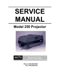
SERVICE
MANUAL
Model 200 Projector
DECLARATION OF CONFORMITY
PER ISO/IEC GUIDE 22 AND EN 45014
Manufacturer: Hughes JVC
2310 Camino Vida Roble
Carlsbad, Ca 92009
USA
Hughes-JVC declares that this product conforms to the following Product
Specifications (Directive/Standard):
Safety:
EN 60950
IEC 950 (1992)
EMC:
EN 55022 (1988) / CISPR-22 (1986) Class "A"
EN 50082-1 (1992) / IEC 801-2(1991)
EN 50082-1 (1992) / IEC 801-3(1984)
EN 50082-1 (1992) / IEC 801-4(1988)
ANSI C63.4-1992, FCC, Part 15, Class A
In addition, the above product complies with the requirements of the Low
Voltage Directive 73/23 EEC and the EMC Directive 89/336/EEC.
104111 First Edition
104111 Rev A
November 1996
February 1997
Confidential and proprietary information.
© Copyright 1993 by Hughes-JVC Technology Corporation.
All worldwide rights reserved.
This manual was produced by Hughes-JVC Technology Corporation and may be
revised without prior notice.
No part of this manual may be reproduced in any form without the express
written permission of Hughes-JVC Technology Corporation.
®
ILA is a registered trademark of Hughes-JVC Technology Corporation.
ii
Model 200 Service Manual
Table of Contents
Safety Information .................................................................................. v
Chapter 1 Introduction
1.1
1.2
1.2
1.4
Acronyms Used in Manual......................................................................... 1-1
Safety ........................................................................................................ 1-2
Updates ..................................................................................................... 1-2
Tool List..................................................................................................... 1-2
Chapter 2 Functional Description
2.1
2.2
2.3
2.4
Introduction................................................................................................ 2-1
Optical Section .......................................................................................... 2-2
Electronics System .................................................................................... 2-7
Image Light Amplifier Technology ............................................................. 2-63
Chapter 3 Service Adjustments
3.1 Arc Lamp Focus and Alignment ................................................................ 3-1
3.2 Arc Lamp Current Setting .......................................................................... 3-4
3.3 Electronic Module Tilt-Up .......................................................................... 3-5
®
3.4 ILA Back Focus ....................................................................................... 3-5
3.5 CRT Mechanical Focus ............................................................................. 3-7
3.6 CRT Rotation............................................................................................. 3-9
3.7 CRT Electronic Focus ............................................................................... 3-10
®
3.8 ILA Overlap ............................................................................................. 3-10
3.9 Jumper Settings (Front/Rear or Inverted Vertical)..................................... 3-12
3.10 Vertical and Horizontal Size Settings ........................................................ 3-13
3.11 Software Updating ..................................................................................... 3-15
®
3.12 Cleaning Lenses, ILA Assemblies and Mirrors ....................................... 3-17
Chapter 4 Maintenance (Removal/Replacement)
4.1 Introduction................................................................................................ 4-1
4.2 Projector Covers........................................................................................ 4-4
4.3 Air Filters ................................................................................................... 4-5
4.4 Arc Lamp Assembly................................................................................... 4-5
4.5 Arc Lamp Power Supply ............................................................................ 4-8
4.6 Low Voltage Power Supply........................................................................ 4-8
4.7 High Voltage Power Supply....................................................................... 4-8
4.8 Raster Timing, System Controller, Video Processor PCBs ....................... 4-10
4.9 Convergence/Deflection PCB.................................................................... 4-11
4.10 Horizontal/Vertical Deflection PCB ............................................................ 4-12
4.11 Video Input Cards (VICs) .......................................................................... 4-13
4.12 Video Amplifier PCB .................................................................................. 4-14
4.13 Scan Reversal Board ................................................................................ 4-16
4.14 CRT/Yoke Assembly ................................................................................. 4-16
®
4.15 ILA Assembly .......................................................................................... 4-18
4.16 Relay Lens ................................................................................................ 4-19
4.17 Projection Lens.......................................................................................... 4-20
4.18 Prism Assembly......................................................................................... 4-21
Model 200 Service Manual
iii
Chapter 5 Troubleshooting
PCB Status LEDs .............................................................................................. 5-1
Error Codes ................................................................................................... 5-4
Troubleshooting Guide...................................................................................... 5-5
Chapter 6 Parts List .............................................................................. 6-1
Appendix A Import/Export ................................................... A-1
Appendix B Glossary ............................................................................ B-1
iv
Model 200 Service Manual
Safety Information
Safety Information
Introduction
Read entire Safety Chapter thoroughly before performing any
maintenance or service on the projector. Only qualified service
personnel should perform procedures and adjustments.
Safety Equipment: Use safety equipment specified in the
projector’s Maintenance training and certification program or
equivalent maintain equipment.
WARNINGS AND CAUTIONS!
Warnings and Cautions in this manual should be read thoroughly
and strictly adhered to. Warning and Caution definitions and
symbols are as follows:
WARNING SYMBOL
Warns user of a
potential electric shock hazard in a procedure or situation that
could result in personal injury if improperly performed.
CAUTION SYMBOL
Warns user of a
potential safety hazard or potential light hazard from ultraviolet,
infrared or bright light that could cause severe eye injury or a
situation that could result in damage to the equipment if
improperly used.
Model 200 Service Manual
v
Safety Information
Installation Safeguards
WARNING!!! Procedures in this service manual require
removing the projector’s covers to access internal component to
remove, replace, service and adjust the projector. Only HughesJVC Certified Technicians are qualified to perform these
procedures. Before removing or replacing any internal
components or subassemblies, verify that the circuit breaker on
the back panel is in the Off position and remove the power plug.
Any adjustments performed that require covers off and power on
should be performed with extreme care. Be especially aware of
all hazardous areas indicated by warning and caution labels.
CAUTION!!! Do not use a forklift to lift the projector without
using a safe shipping pallet. Lifting the projector without
supporting the weight at the foot locations can cause severe
damage to the projector.
If there is any visible damage to the power cable, disconnect
power to the projector until the damaged cable is replaced. Install
the projector on a smooth, vibration-resistant level surface, or
ceiling mount, in an area free from dust and moisture. Do not
place the equipment in direct sunlight or near heat-radiating
appliances. Smoke, steam and exposure to direct sunlight could
adversely affect the internal components.
If mounting the projector, use hardware that can handle a
minimum of three (3) times the projector weight.
Heat Safeguards
Fans and Ventilation: The projector has multiple fans to cool the
system. Do not block the intake or outflow of any fans. Heat is
emitted within the system and must be properly dissipated to keep
the system running correctly. Blocking air intake or exhaust ports
can lead to projector overheating. Do not enclose the unit in a
restricted space (refer to the physical access and thermal
clearance illustration guidelines).
vi
Model 200 Service Manual
Safety Information
CAUTION! Do not unplug the power cord until after the arc
lamp fan has stopped running. This fan protects the arc lamp from
overheating. Disconnecting power before the cooling fans have
stopped running can shorten Arc Lamp life.
Light Safeguards
Ultra Violet and Infrared Light
Eye and face protection from ultra violet light and infrared light in
accordance with the following conditions:
1. X3 (up to 375 nanometers), ANSI approved, shade
goggles must be worn by anyone near the projector
when it is lit and the cover is off.
2. X5 (375 to 700 nanometers), ANSI approved, shade
goggles when actually working on the projector
near the arc lamp source.
WARNING, BRIGHT LIGHT!!!
Never look directly at the Arc Lamp, the lighted Projection
Lens or into the lamp housing, from any distance, when the
projector is on. Direct exposure to light of this brightness can
cause severe eye injury.
Dangerous levels of ultraviolet and infrared radiation,
dangerous glare, very high temperatures (180°C to 300°C) and
high internal gas pressure are present at the Xenon Arc
Lamp. The lamp is contained in a protective reflector housing
module and should not be operated outside this housing or
outside of the projector. When replacement is needed, the arc
lamp must be replaced as an entire module, as shown in this
Model 200 Service Manual. Do not open the lamp housing or
attempt to replace the Arc Lamp inside its module! Do not
touch the Arc Lamp, or any connections, when the lamp is
ignited or is arcing. Any servicing of the Arc Lamp must
remain restricted to Hughes-JVC certified maintenance
personnel.
Model 200 Service Manual
vii
Safety Information
Electrical Safeguards
High voltage access. Front
and rear covers contain
safety interlocks. Defeat
restricted to Hughes-JVC
certified service personnel!
WARNING!!! High Voltage points up to 40,000 volts
are exposed inside the covers. Allow at least one minute for
the high voltage to bleed off, even after power is turned off.
Due to high voltage danger, DO NOT TOUCH
•
•
•
•
•
CRT cables. These cables can cause severe shock from a
tiny, invisible crack or hole and should never be touched
while projector power is on.
CRT anodes.
Main power ± supply posts.
Arc Lamp main power ± posts.
CRT yoke assemblies and other proximity electrical
®
assemblies, components and wiring. If performing the ILA
Back Focus, CRT Mechanical Focus, CRT rotation, or
®
ILA Overlap adjustment, as outlined in Chapter 3, always
use an ANSI/ASTM 10,000 volt rated glove. Periodically
check the condition of the gloves for cracks.
Power Supply
The projector operates from a 100V - 240V, 20 Amp, singlephase, 50/60 Hz AC power source. Ensure local power source
matches these requirements before operating!
For continued safe and reliable operation, only use cables
supplied by the manufacturer for power and signal connections.
Fluid Safeguards
Certain components of the projector contain fluid. If any fluid from
the projector contacts the skin, wash off with soap and water. If
any fluid from the projector splashes into the eyes, rinse with cool
running water.
viii
Model 200 Service Manual
Safety Information
Ventilation and Foreign Object Retrieval
CAUTION! Ensure projector’s multiple fans are free from
obstructions and operating properly. Air filters are located at vent
ports on the cover. Air filters require periodic cleaning to ensure
adequate cooling of the projector (Section 4.3). Ensure that all
vent ports are clear of obstructions.
Keep the inside of the projector free from foreign objects, such as
hairpins, nails, paper, etc. Do not attempt to retrieve any object or
insert metal objects such as wire and screwdrivers inside the unit.
If an object falls inside the projector, immediately unplug the
projector and call a Hughes-JVC certified technician to remove
object.
Model 200 Service Manual
ix
Safety Information
x
Model 200 Service Manual
Chapter 1---Introduction
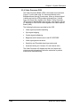
1.0 Introduction
This Service Manual is designed to be used with the Model 200
User’s Guide. This service manual provides information on the:
— Projector functional description;
— Service adjustments, removal and replacement of
subassemblies; and
— Troubleshooting.
The user’s guide covers the projector’s installation, operation,
setup adjustments, and specifications. Together the service
manual and user’s guide provide a qualified service person with
information to operate and maintain the projector.
1.1
Safety
This projector contains high voltages and high intensity light
sources in its internal system and power supplies. Read entire
Safety Chapter at the front of this manual before performing any
adjustments or maintenance.
When performing procedures that call for projector’s power to be
on, always wear high voltage gloves (ANSI/ASTM 10,000 volt
rated) when working around the CRTs, Arc Lamp or power
supplies. Wear safety goggles (rated X5) when working anywhere
near the light path from the Arc Lamp or the projection lens at all
times.
1.2
Updates
Hughes-JVC will periodically provide bulletin and /or manual
supplements to ensure the accuracy of this service manual.
1.3
Tool List
The following tools are required to perform service adjustments:
All Purpose Tools=Diagonal Sidecutters, Wirestrippers,
Slot Adjustment Screwdriver (Tweeker),
Mirror/Magnet Pick-Up Tool, Flashlight, 6” Crescent
Wrench, Needlenose pliers, 6” Vise Grips
Balldriver, 1.5mm
Balldriver, 3mm
Balldriver, 3mm, Long
Balldriver, 4mm
Balldriver, 5mm, Long, T-handle
Balldriver, 6mm
Model 200 Service Manual
1-1
Chapter 1---Introduction
Balldriver, 8mm
Ballpoint L-Wrench Set, 1.5-5mm
Delrin .100 Hex Alignment Tool
Gloves, ANSI/ASTM 10,000 volt rated, Safety
Goggles, Safety, x3(covers on) and x5(covers off)
Hex Ballpoint Driver, 3mm
Hex Ballpoint Driver, 5mm
Nutdriver, 10mm
Nutdriver, 11mm (or 7/16”)
Nutdriver, 5mm
Nutdriver, 7mm
Nutdriver, 8mm
Screwdriver, Phillips, #1
Screwdriver, Phillips, #2
Screwdriver, Pozidrive, #1
Screwdriver, Pozidrive, #2
Screwdriver, Slot ¼”
Screwdriver, Slot, ½”
Screwdriver, Slot, 3/16”
Socket, ¼” drive, 7mm-deep
1.4
Acronyms Used in this Manual
ALPS
CDB
CH
CPU
CRT
EMI
FLASH
EPROM
FPGA
F to V
G2
HVDB
HDTV
Hz
HSYNC
HVDB
HVPS
IIC
®
ILA
I/O
I/R
kHz
LED
LVPS
NTSC
PAL
PCB
PLL
1-2
Arc Lamp Power Supply
Convergence/Deflection Board
Channel
Central Processing Unit
Cathode Ray Tube
Electromagnetic Interference
Erasable Programmable Read-Only Memory
Field Programmable Gate Array
Frequency to Voltage
CRT Grid 2
Horizontal/Vertical Deflection Board
High Definition Television
Hertz
Horizontal Sync
Horizontal/Vertical Deflection Board
High Voltage Power Supply
Inter-Integrated Circuit
Image Light Amplifier
Input/Output
Infrared
Kilohertz
Light Emitting Diode
Low Voltage Power Supply
National Television Standards Committee
Phase Alternating Line
Printed Circuit Board
Phase Lock Loop
Model 200 Service Manual
Chapter 1---Introduction
PLUGE
RAM
RGB
RGBHV
ROM
RTG
SCB
SECAM
SRB
SYNC
TTL
UL
UV
VAB
VCO
VIC
VIN
VPB
VSYNC
VTR
YC
Model 200 Service Manual
Picture Line-Up Generating Equipment
Random Access Memory
Red, Green and Blue
Red, Green, Blue, Horizontal, Vertical
Read Only Memory
Raster Timing Generator
System Controller Board
Sequential couleur a memoire (sequencial
color with memory
Scan Reversal Board
Synchronization
Transistor-Transistor Logic
Underwriter Laboratories
Ultraviolet
Video Amplifier Board
Voltage Controlled Oscillator
Video Input Card
Video Input
Video Processor Board
Vertical Sync
Video Tape Recorder
Luminance/Chrominance
1-3
Chapter 1---Introduction
1-4
Model 200 Service Manual
Chapter 2---System Description
2.0 System Description
Contents
2.1 Introduction .............................................................................. 2-1
2.2 Optical System......................................................................... 2-2
2.2.1 Image Path................................................................... 2-2
2.2.2 Arc Lamp Light Path .................................................... 2-4
2.3 Electronics System .................................................................. 2-7
2.3.1 General Description ..................................................... 2-7
2.3.2 Power Supplies ............................................................ 2-8
2.3.3 Video Input Cards ........................................................ 2-14
2.3.4 Video Processor PCB .................................................. 2-24
2.3.5 Video Amplifier PCB .................................................... 2-30
2.3.6 System Controller PCB ................................................ 2-34
2.3.7 Raster Timing Generator PCB ..................................... 2-40
2.3.8 Horizontal/Vertical Deflection PCB .............................. 2-45
2.3.9 Convergence/Deflection PCB ...................................... 2-51
2.3.10 Scan Reversal PCB ..................................................... 2-57
2.3.11 Backplane PCB............................................................ 2-62
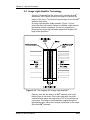
2.4 Image Light Amplifier Technology ........................................... 2-63
2.1 Introduction
The assemblies and components in the Model 200 projector are
contained mainly in the five sections below:
•
The Optics Assembly Section is located at the front area of
the projector. The Optics Assembly Section includes the
Condensing Lens, Cold Mirror/IR Filter (
CAUTION!: The term "cold mirror" is used because
the mirror passes infrared light and its reflection contains only
"cold' light that does not transmit appreciable heat. As a result
of the absorption of infrared heat radiation, "cold" mirrors can
get very hot.), Ultraviolet Filter, Dichroic Mirror Assembly,
Prisms, Combining Prism, Image Mirrors, and the Zoom
Projection Lens.
•
The Arc Lamp Assembly section is located in the right front
area of the unit. It contains the Ignitor, Laser Power Supply,
Xenon Arc Lamp and Elliptical Reflector.
Model 200 Service Manual
2-1
Chapter 2---System Description
•
The Power Supply Section is located at the right front area of
the projector below and to the rear of the Arc Lamp. It contains
the Low Voltage Power Supply, the High Voltage Power
Supply, and the Arc Lamp Power Supply.
•
The Projector Electronics Section is located mainly in the
back half of the projector. It consists of the Electronics Module
that houses 6 of the electronics printed circuit boards used in
the projector, and their associated cabling. It also contains the
Backplane board which is used to electrically interconnect the
printed circuit boards, power supplies and various other units
in the projector and the Video Input Cards that interface with
different kinds of input signals.
•
The CRT Section is located beneath the electronics card cage
®
and contains the 3 CRTs, 3 Relay Lenses, 3 ILA s and the
Video Amplifier Board.
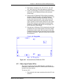
2.2 Optical System
Introduction: The Model 200 Optics Assembly divides white light
from the Arc Lamp into its three color components, Red, Green
and Blue. This light is then modulated with the image signal to
form three single color images. The light is then recombined at the
4P (combining) prism and transmitted through the projection lens
to the projector screen. The explanation below is divided into two
sections. The first section follows the image path from the CRT to
the projector screen. The second section follows the high intensity
®
light path from the Arc Lamp Ignitor to the ILA assemblies, where
it combines with the image. The Red, Green, and Blue image and
light paths are identical. Refer to Figure 2-1.
CAUTION! The alignment of system optical
components is critical. Replacement of individual mirrors or prisms
requires removing the projector cover and must be performed only
by Hughes-JVC Certified technicians. Consult the factory before
removing or aligning any mirrors or prisms.
2.2.1 Image Path
CRT Assemblies: The three CRT/Yoke assemblies are located
beneath the Electronics Module card cage. Two exhaust fans at
the rear help cool the CRT assemblies. Each CRT is sent a red,
green, or blue signal, but they do not emit a red, green, or blue
color, as in traditional projectors. The CRTs are not used as a
2-2
Model 200 Service Manual
Chapter 2---System Description
primary light source. The light output to the screen is the function
of the Arc Lamp. The purpose of the CRTs is to generate an
®
image and to control the amount of modulation the ILA
assemblies introduce on the light coming from the Arc Lamp. The
Red, Green, and Blue image signals are routed to the CRTs from
the Video Amplifier Board through the CRT socket connectors.
Relay Lens: The relay lens picks up the image from the face of
the CRT and focuses the image to the ILA® assembly.
Image Light Amplifier (ILA®) Assembly: The CRT image is
received from the relay lens onto the input side of the ILA®
assembly. The input and output sides of the ILA® assembly are
isolated from each other electrically and optically but are coupled
electrostatically.
At the same time as the image is received at the input side of the
ILA® assembly, the output side of the ILA® assembly is receiving
high intensity light from the arc lamp through the prism. This high
intensity light is modulated (changing its polarization) by the signal
on the input side of the ILA® assembly. The light is then reflected
®
back from the output side of the ILA assembly, then travels
through the prism to be picked up by the projection lens.
NOTE: The prism reflects horizontally polarized light and passes
vertically polarized light. Light from the arc lamp is polarized
horizontally and reflects from the prism into the ILA® assembly
then back out again, after being modulated by the image signal
into vertically polarized light. The vertically polarized light then
passes through the prism to the projector lens. In this manner the
ILA® assembly combines the image from the CRT with the high
intensity light from the arc lamp. Thus, the maximum brightness of
the screen image is not dependent on the brightness of the CRT,
but on the light from the arc lamp.
®
For a more detailed description of how the ILA assembly works,
refer to Section 2.7 below.
Polarizing Prism: The polarizing prism receives the high intensity
light from the xenon arc lamp and polarizes the light horizontally.
The prism reflects virtually all of this light toward the ILA®
assembly. This light is then modulated (altered) into a vertical
plane by the image on the input side of the ILA® assembly and
then reflected back into the same prism. Since the prism reflects
only horizontal light and passes vertical light, this high intensity,
vertically polarized image goes straight through the prism toward
the Combining Prism. Light that is not completely polarized
horizontally or vertically passes through the prism in varying
degrees of brightness, according to how polarized it is (fully
polarized light resulting in maximum brightness on the screen).
Image Mirror: The Image Mirrors direct the blue and red images
toward the Combining Prism.
Model 200 Service Manual
2-3
Chapter 2---System Description
Combining (4P) Prism: The combining prism consists of
separate prisms that polarize each of the three high intensity
signals and direct them toward the projection lens.
Projection Lens: The Projection Lens picks up the high intensity
image from the Combining Prism and transmits it to the projector
screen.
2.2.2 Arc Lamp Light Path
The Arc Lamp assembly produces the high intensity light used to
transmit bright images to the screen. It consists of a Xenon Arc
Lamp containing xenon gas under pressure, an ignitor assembly
that provides the spark to light the arc lamp, and a laser power
supply to provide the boost voltage to the Ignitor. An exhaust fan
helps keep the arc lamp cool. The description below follows the
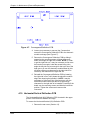
sequence of the light path. (See Figure 2-1).
Ignitor and Laser Power Supply: The Laser Power Supply
provides a boost voltage through a spark gap to the Ignitor circuit
which then provides a momentary High Voltage, (32,000 volts), to
excite the xenon gases inside the Xenon Arc Lamp. After the arc
lamp ignites, it is maintained ON by high current and low-voltage
(approximately 37.5 amps and +20 volts). The arc lamp Ignitor
and Laser Power Supply are mounted next to the arc lamp, inside
the Arc Lamp assembly housing.
WARNING!!!
The Xenon Arc Lamp produces high
intensity white, ultraviolet and infrared light capable of severe eye
injury. Never look directly at or touch the Xenon Arc Lamp.
Service should be performed by Hughes-JVC certified
technicians only.
Xenon Arc Lamp/Condensing Lens: High pressure, ionized
xenon gas supports a high-current electrical arc to produce the
intense, white light used in the Model 200 projector. The high
intensity light output from the Xenon Arc Lamp is reflected by an
elliptical metal reflector to a Condensing Lens where the light
beam is condensed and directed to the Cold Mirror.
Cold Mirror/IR Filter and Ultraviolet Filter: The arc lamp light
beam passes through the Condensing Lens to the Cold Mirror and
Infrared Filter which removes most of the IR light, then through the
Ultraviolet filter which removes most of the UV light. The light
beam then proceeds toward the Dichroic Mirror Assembly. In this
manner most of the IR and UV light is filtered out before the light
beam enters the more sensitive portions of the optics, leaving only
the visible portion.
Dichroic Mirror Assembly: The condensed and filtered white
light beam enters the Dichroic Mirror Assembly which separates
(dichroic mirrors reflect only one color and pass all others) the
2-4
Model 200 Service Manual
Chapter 2---System Description
light into its Red, Green and Blue components. The first mirror in
®
the Dichroic Mirror Assembly reflects blue light to the blue ILA
®
assembly, the second mirror reflects green light to the green ILA
®
assembly, and the third reflects red light to the red ILA assembly.
®
Thus, each ILA is sent only one color of light.
Prepolarizers and Polarizing Prisms: Each individual light beam
is polarized (directed) toward its own Polarizing Prism where it is
directed toward the output side of its ILA® Assembly and
combined with the signal from the input side of the ILA®
Assembly.
Each of these three light beams independently combine with the
image in their own (Red, Green or Blue) color systems at the ILA®
assemblies as described in Section 2.2.1, Image Path.
Model 200 Service Manual
2-5
Chapter 2---System Description
Figure 2-1. Optical System Block Diagram
2-6
Model 200 Service Manual
Chapter 2---System Description
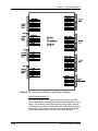
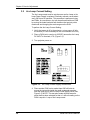
2.3 Electronics System
2.3.1 General Description
The Model 200 Electronics System includes nine printed circuit
assemblies. They provide all the controlling voltages and signals
to adjust and correct picture settings, geometry, convergence, and
shading (see Chapter 4 of the User’s Guide). The Electronics
System also controls video and sync input signals, LED displays
on PCBs at the rear and side of the projector, two RS-232
communications ports, and two IR receivers for remote control of
the projector.
The descriptions in this portion of the manual are based on an
overall Electronics System block diagram and simplified block
diagrams for each of the nine printed circuit assemblies. The
diagrams and descriptions serve two purposes; first, to provide the
technician with an overall grasp of how the system works and how
each assembly works with other assemblies in the system,
second, to provide the technician with enough information to
troubleshoot to the assembly level, if needed.
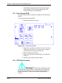
Figure 2-2 provides an overall System Block Diagram to show how
the Optical System, Arc Lamp, and Electronics System combine to
provide the bright screen image.
LAMP
COLD MIRROR
IGNITER
INTEGRATOR
CONDENSING
LENS
LINE
FILTER
UV FILTERS
HIGH
VOLTAGE
CROSS
DICHROICS
HIGH VOLAGE FOCUS
POWER SUPPLY
LOW VOLTAGE
POWER SUPPLY
G2
TO CRTS
VIDEO INPUT
CARDS
VIDEO
PROCESSOR
RASTER TIMING
GENERATOR
P LA N E
CONVERGENCE
DEFLECTION
BACK
AC
INPUT
LAMP
POWER SUPPLY
SYSTEM
CONTROLLER
SCAN REVERSAL
HORIZONTAL
VERTICAL
DEFLECTION
VIDEO AMPLIFIERS
TO YOKES
PROJECTION
LENS
CRTS
RELAY
LENSES
OPTICS MODULE
ILA’S
ELECTRONICS MODULES
Figure 2-2. Model 200 System Block Diagram
Model 200 Service Manual
2-7
Chapter 2---System Description
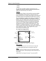
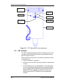
2.3.2 Power Supplies
The Model 200 includes three power supply assemblies.
•
Low Voltage Power Supply
•
Arc Lamp Power Supply
•
High Voltage Power Supply
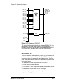
Low Voltage Power Supply (LVPS)
P76
P75
AC
1
INPUT 3
5
Line
Earth
Neutral
LV Ret
/LV_ENA
/LV_OK
+24v Fans
+5.1v STBY
+5.1v
+6.2v
+15V
-15v
+80V
/COVER_ON
/FAN_ENA
1-7
8
To P8 on
9
10 Backplane
11
12
13
14
15
16
17
18
Figure 2-3. LVPS Input/Output Diagram
Main Functions:
•
Provide all the low voltages needed by the projector.
•
Provide standby power when the projector is OFF.
•
Provide power for all cooling fans.
Inputs:
The Low Voltage Power Supply receives AC input power directly
from the power source. The input range is from 100 VAC to 240
VAC, at 50 or 60 Hz.
/LV_ENA: Enabling signal from the System Controller Enables the
LVPS when the System Controller receives a Power On
command.
/FAN_ENA: From System Controller. Enables the +24v standby
voltage for the projector fans.
/COVER_ON: Cover interlock signal. Indicates both covers in
place. Enables the non-standby outputs.
Outputs:
+ 5.1VDC Main
+ 5.1VDC Standby
+ 6.2VDC
± 15VDC
2-8
Model 200 Service Manual
Chapter 2---System Description
+ 24VDC
+ 80VDC
/LV_OK: When /LV-ENA is enabled, this diagnostic signal
indicates to the System Controller the status of the non-standby
supply (all outputs working or not working).
Operation:
The main power is filtered via the input filter to prevent radiation
from escaping back to the power line. From the line filter, AC
power is fed into the Low Voltage Power Supply module where AC
is rectified, filtered, and compensated for power factor correction.
The +5.1V Standby is on whenever AC power is connected to the
projector and the circuit breaker on the rear panel is in the On
position. The +24V standby power for the fans turns on when the
/FAN_ENA signal is received from the System Controller (this
turns off in 5-8 minutes if power is not turned on by the remote
control or a PC). All other voltages supplied by the LVPS are
activated when power is turned on at the remote or PC. These
include +5.1V for digital components, +6.2V for CRT filaments,
±15V for analog circuits, and the +80V supply which is used by the
High Voltage Power Supply, Video Amplifier PCB, and the
Horizontal/Vertical Deflection PCB.
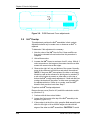
Arc Lamp Power Supply (ALPS)
P74
P71
AC
1
INPUT 3
5
Line
Earth
Neutral
LAMP_OUT
LAMP_RET
P72
1
To P9 on
2
Backplane
3
4
5
6
1
2
To Lamp
Module, J74
P73
GND
/LAMP_LIT
/LAMP_OK
/LAMP_ENA
COVER_ON
GND
LAMP_OK
GND
1
2
To Lamp
Module, J74
Figure 2-4. Arc Lamp Power Supply, Block Diagram
Main Functions:
• Provides ignition power to turn the Xenon Arc Lamp ON.
• Provides steady state power to maintain the lamp ON.
Inputs:
The Arc Lamp Power Supply receives AC input power directly
from the power source. The input range is from 100-240 VAC, at
50 or 60 Hz.
/LAMP_ENA: From System Controller. Turns on the ALPS.
Model 200 Service Manual
2-9
Chapter 2---System Description
/COVER_ON: Cover interlock signal. Indicates both covers are in
place.
/LAMP_OK: Tells the ALPS that the lamp is installed, the
temperature is within limits, and the lamp cooling blower is
working.
Outputs:
+140 VDC boost voltage to the Laser Power Supply.
Voltage: 18 to 25 VDC to maintain the arc lamp ON.
Current: 30 to 38 amps to maintain the arc lamp ON.
LAMP_OUT: Lamp output voltage, positive.
LAMP_RTN: Lamp return.
/LAMP_LIT: Signal to SCB that the lamp is lit.
Operation:
Two signals (/COVER_ON and /LAMP_OK) are required in order
for the arc lamp to light. /COVER_ON from the cover interlock
switches tells the Arc Lamp Power Supply that the covers are in
place and the interlock switches are pressed down. /LAMP_OK
informs the System Controller that the lamp is installed (a
mechanical switch activates when lamp is installed). The System
Controller sends the /LAMP_ENA signal to the Arc Lamp Power
Supply. The /LAMP_ENA signal turns on the ALPS.
The Arc Lamp Power Supply then provides the +140 VDC boost
voltage to a spark gap and high voltage transformer which steps
up the voltage to approximately 32KV and ignites the Xenon Arc
Lamp. After the Arc Lamp is lit, it is maintained on by the ALPS at
a steady 20 volts and 37 amps. The /LAMP_LIT signal output
informs the System Controller if the lamp is lit or not.
The Arc Lamp Power Supply is electrically and magnetically
shielded to prevent noise or disturbances in the CRTs or other
circuitry.
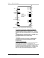
High Voltage Power Supply (HVPS)
The High Voltage Power Supply (HVPS) is located on top of the
LVPS on the right side of projector ( as viewed from rear). This
supply provides the anode, focus, and screen voltages required
for the three CRTs in the Model 200 projector.
The following functions are provided by HVPS:
2-10
•
Phase locked loop circuit for synchronization to the horizontal
sync
•
Generation of anode voltages (25 KV) for all three CRTs
(RGB)
Model 200 Service Manual
Chapter 2---System Description
•
Generation of focus voltage (G3) for all three CRTs (RGB)
•
Generation of screen (G2 supply-Black Level) voltage for all
three CRTs
•
Generation of G1 supply (Blanking) voltage
•
Dynamic focus amplifier using H and V parabolas
•
External ON/OFF and generation of /HV_OK signal
G A N O D E J5 9-1
B A N O D E J60-1
FR OM LVPS
R F O C U S J58-1
+ 80V
8
+15 V
9
-15
/H V E N A (/V A _O K )
(From VPB)
HIGH
VOLTAGE
POWER
SUPPLY
10
G F O C U S J59-1
B F O C U S J60-1
J44
3
12
FR OM C D BO AR D
1
H P A R A B O LA
6
V PARABOLA
13
ARC GND
G 2 S U P P LY
J45
11
5
G 1 S U P P LY
/H V O K
TO C R TS
R A N O D E J58-1
14
T O C R T S V IA V A B
J45
H V P S _S Y N C
TO C R TS VIA VAB
FR OM RTG
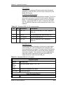
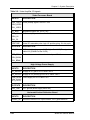
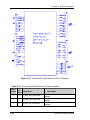
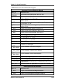
The High Voltage Power Supply I/O diagram (Figure 2-5) and the
list of inputs and outputs (Table 2-1), provide an understanding of
the operation of the HVPS to allow the technician to perform
module level troubleshooting.
Figure 2-5. High Voltage Power Supply, I/O Diagram
The HVPS Input/Output
This section provides a comprehensive description of the inputs to
and outputs from the HVPS. The I/O descriptions are arranged by
the source/destination of the signal. The format used is such that
the assembly communicated with is used as the primary heading
of each output. Input refers to an input to the HVPS. Output refers
to an output from the HVPS. In each case the signals direction is
noted.
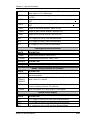
Table 2-1. High Voltage Power Supply I/O signals
Raster Timing Generator PCB
INPUT
DESCRIPTION
Model 200 Service Manual
2-11
Chapter 2---System Description
HVPS_SYNC
Square wave HCT level with 50 or 33% duty cycle synchronized to
horizontal sync.
Video Processor PCB
INPUT
DESCRIPTION
/HV_ENA
The HVPS enable line. A low enable the HVPS (VA_OK from VPB).
Video Amplifier PCB
OUTPUTS
DESCRIPTION
G1_SUPPLY
DC supply about -150 V for driving the G1 of CRTs
G2_SUPPLY
DC supply about 1.3 KV for driving the G2 of CRTs
ARC_GND
Return (ground) line for the CRT anodes
Convergence/Deflection PCB
INPUTS
H_
PARABOLA
DESCRIPTION
Horizontal parabola for use by the dynamic focus amplifier
V_
PARABOLA
Vertical parabola for use by the dynamic focus amplifier
System Controller PCB
OUTPUT
DESCRIPTION
/HV_OK
The high voltage status line. Low = operational HVPS
Low Voltage Power Supply
INPUTS
DESCRIPTION
+ 15V
+ 15 V for use by the HVPS
+ 80V
+ 80 V for use by the HVPS
- 15V
- 15V for use by the HVPS
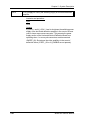
2-12
Model 200 Service Manual
Chapter 2---System Description
CRTs
OUTPUTS
DESCRIPTION
RED_ANODE
GRN_ANODE
BLU_ANODE
Anode supply for the three CRTs. About 25 KV
RED_FOCUS
GRN_FOCUS
BLU_FOCUS
Focus voltage for the three CRTs. About 7 KV
Interlocks and protection:
This section describes the interactions between boards where one
board may cause others to perform protection functions.
Input
A high signal at /HV_ENA shuts off the HVPS.
Model 200 Service Manual
2-13
Chapter 2---System Description
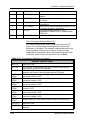
2.3.3 Video Input Cards
The four types of Video Input Cards that can be used with the
Model 200 Projector are:
•
Standard RGB Video Input Card, which is supplied with each
projector and is used for RGB standard formats
•
Optional Four Input RGB VIC used in a similar manner as a
switcher.
•
Optional HDTV VIC used for High Definition Television.
•
Optional Quad Standard Decoder VIC used for NTSC, PAL
SECAM and other composite sources.
Standard RGB Video Input Card (RGB_VIC)
The RGB Video Input Card (RGB_VIC) is located on the back side
of the projector. It has five BNC input connectors. It provides the
RGB and sync interface for the Model 200 projector.
The following functions are provided by the RGB VIC:
•
Video and sync interface for red, green and blue
•
LED indication
•
IIC serial bus interface
B2
RED
GREEN
BLUE
HORIZ
VERT
IIC_CLK
IIC_DATA
IIC_INT
+5.1Vstby
+5.1V
+15V
-15V
B4
B6
B8
B10
RED_VIC
GREEN_VIC
BLUE_VIC
H_VIC
V_VIC
B13
A13
A12
A16
B16
B15
B14
IIC
12
Pin callouts are to P12, P14, or P18
depending on which VIC slot is used.
A1
A2
A3
/SEL_VIC
GND
GND
GND
Figure 2-6. Standard RGB VIC I/O
Video and sync interface for red, green and blue
The RGB VIC provides a high bandwidth interface for the three
color video signals. The video signals are routed to the Backplane
Board without any distortion or modification. The sync signals
(horizontal and vertical) are also directly connected to the
Backplane Board.
2-14
Model 200 Service Manual
Chapter 2---System Description
LED indication
The RGB VIC includes an LED which glows when the board is
selected (i.e. when the /SEL_CH line is low) as the input for the
Model 200 Projector.
IIC serial bus interface section
The RGB_VIC is controlled by the serial bus interface. The IIC bus
comes from the System Controller Board through the Backplane
Board. The information transferred over the IIC bus is indicated
below (I = input to the RGB VIC, and O = output from the RGB
VIC). The RGB VIC does not use the interrupt line of the IIC bus
interface:
Table 2-2. Standard RGB VIC IIC communication
I/O
Bits Information
Description
I
1
/SEL_CH
Select line for the RGB_VIC. Low = Selected
RGB_VIC.
O
4
VIC_ID
VIC identification lines. 0000 for RGB_VIC.
O
1
VIC_MODEL
Revision of the RGB_VIC.
O
1
/VIC_OK
RGB_VIC status line. Low = operational
RGB_VIC.
The RGB_VIC I/O
This section provides a description of the inputs to and outputs
from the RGB_VIC. The I/O descriptions are arranged by the
source/destination of the signal. The format used is such that the
assembly communicated with is used as the primary heading of
each group of signals. Those signals are further subdivided into
inputs and outputs. Input refers to an Input to the RGB_VIC,
output refers to an output from the RGB_VIC.
Table 2-3. Standard RGB VIC I/O signals
Projector Inputs
INPUTS
DESCRIPTION
RED
GREEN
BLUE
Video input signals. about 0.7 to 1 VPP
HORIZ.
Horizontal or composite sync signal
VERTICAL
Vertical sync signal
Video Processor Board
OUTPUTS
DESCRIPTION
Model 200 Service Manual
2-15
Chapter 2---System Description
/SEL_VIC
Select line for VIC. A low indicates the RGB_VIC is selected.
RED_VIC
GRN_VIC
BLU_VIC
Video signals. about 0.7 to 1 VPP
H_VIC
Horizontal or composite sync signals
V_VIC
Vertical sync signals
System Controller Board
INPUTS
DESCRIPTION
IIC_CLK
IIC clock line. Unidirectional clock line for control of synchronous
data transfer over the IIC bus interface.
IIC_DATA
IIC data line. Bidirectional serial line for synchronous data transfer
between system control board and the RGB_VIC.
OUTPUTS
DESCRIPTION
/IIC_INT
IIC interrupt line. RGB_VIC does not initiate an interrupt.
Low Voltage Power Supply
INPUTS
DESCRIPTION
+5.1 V
+5.1 V supply for use by RGB_VIC.
+15 V
+ 15 V supply for use by RGB_VIC.
-15 V
-15 V supply for use by RGB_VIC.
+ 5.1 V_stby
+ 5.1 V stand by supply for use by RGB_VIC.
Interlocks and protection
Input: None
Outputs: None
Quad Input RGB VIC
The Quad Input RGB VIC consists of four sets of RGBHV inputs
and operates in a manner similar to a switcher. The four inputs are
multiplexed so that only one is enabled at a specific time.
Software selects the desired input channel through the IIC bus
and ensures that only one RGB VIC is enabled. When one of the
channels assigned to the Quad RGB VIC is selected, the
/SEL_VIC line to the Video Processor is enabled.
2-16
Model 200 Service Manual
Chapter 2---System Description
RED_CH1
RED_CH2
RED_CH3
RED_CH4
GRN_CH1
GRN_CH2
GRN_CH3
GRN_CH4
BLU_CH1
BLU_CH2
BLU_CH3
BLU_CH4
4:1
VIDEO
MUX
and
BUFFERS
RED_VIC
GREEN_VIC
BLUE_VIC
H_VIC
V_VIC
HOR_CH1
HOR_CH2
HOR_CH3
HOR_CH4
VER_CH1
VER_CH2
VER_CH3
VER_CH4
IIC_CLK
IIC_DATA
IIC_INT
IIC
/SEL_VIC
+5.1Vstby
+5.1V
+15V
-15V
Figure 2-7. Quad Input RGB VIC
The same functions performed by the Standard RGBHV VIC are
performed by the Quad Input RGB VIC. The description of
operation and pinouts are the same as the Standard RGBHV VIC.
One of four LEDs indicates which of the four RGB inputs is
currently active.
HDTV YPbPr VIC
This color decoder video input card (YPbPr_VIC) is located on the
back side of the projector and contains three BNC input
connectors which can be used for two different inputs, YPbPr or
GBR. This board converts these color component signals to RGB
type video signals.
The following functions are provided by YPbPr_VIC:
•
Video input and output buffers
•
Conversion of color components signals to RGB video signals
•
Separation of syncs from the Y/G input signal
•
Hue, sharpness, gamma, and color adjustment
•
Selection of RGB input or color component input
Model 200 Service Manual
2-17
Chapter 2---System Description
•
LED indication
•
IIC serial bus interface
Y/G
B2
RED
Pb/B
B4
GRN
Pr/R
B6
BLU
IIC_CLK
IIC_DATA
B13
A13
B8
+5.1V_STBY
+5.1V
+15V
-15V
HOR
A16
B16
B12
/SELECT
B15
B14
Pin callouts are to P12, P14,
or P18, depending on which
VIC slot is being used.
Figure 2-8. HDTV YPbPr VIC Input/Output Diagram.
This VIC accepts two types of video signals, color components
(YPbPr) and RGB signals. In either case the output of this VIC is
RGB type signals. If the inputs are color components they will be
converted to RGB type signals.
The selection between color component input mode and RGB
input mode is controlled by an input. This input is controlled by the
System Controller Board via the IIC serial bus interface.
LED indication
There are two LEDs on this VIC. The RGB LED glows when the
YPbPr_VIC is selected and is in RGB input mode. The YPbPr LED
glows when the YPbPr_VIC is selected and is in YPbPr input
mode. Both LEDs are off when the YPbPr_VIC is not selected as
the input to projector. Only one LED can be on at one time.
IIC Interface
The YPbPr_VIC is controlled by the serial bus interface. The IIC
bus comes from the System Controller Board through the
Backplane Board. All required adjustments for this board are
provided via the IIC serial bus interface. The information
transferred over the IIC bus is indicated below (I = input to
YPbPr_VIC, and O = output of YPbPr_VIC). The selection of this
VIC is accomplished through the IIC control bus which provides
the /SEL_VIC signal.
2-18
Model 200 Service Manual
Chapter 2---System Description
Table 2-4. HDTV VIC IIC Interface
I/O
Bits
I
1
Information
Description
/SEL_YPbPr
Selects YPbPr input mode for the YPbPr_VIC.
Low = Selected YPbPr input mode.
I
1
/SEL_RGB
Selects RGB input mode for the YPbPr_VIC.
Low = Selected RGB input mode.
I
8
GAMMA
Data for adjustment of Gamma correction
I
8
COLOR
Data for adjustment of color
I
8
HUE
Data for adjustment of hue
I
8
SHARPNESS
Data for adjustment of sharpness
O
4
VIC_ID
VIC identification lines. 0001 for YPbPr_VIC
O
1
VIC_MODEL
Revision of the YPbPr_VIC.
O
1
/YPbPr_OK
YPbPr_VIC status line. Low = operational
YPbPr_VIC
The HDTV YPbPr_VIC I/O
This section provides a comprehensive description of the inputs to
and outputs from the YPbPr_VIC. The I/O descriptions are
arranged by the source/destination of the signal. The format used
is such that the assembly communicated with is used as the
primary heading of each group of signals. Those signals are
further subdivided into inputs and outputs. Input refers to an Input
to the YPbPr_VIC, output refers to an output from the YPbPr_VIC.
Table 2-5. HDTV VIC Signals
Projector Inputs
INPUT
DESCRIPTION
Y/G
Pb/B
Pr/R
Video input signals-about 0.7 to 1 VPP
Video Processor Board
OUTPUT
DESCRIPTION
/SELECT
Selection indicator for VIC. Low indicates the selected YPbPr_VIC.
RED
GRN
BLU
Video signals. about 0.7 to 1 VPP
Model 200 Service Manual
2-19
Chapter 2---System Description
HOR
Composite horizontal / vertical sync signal
System controller board
INPUTS
DESCRIPTION
IIC_CLK
IIC clock line. Unidirectional clock line for control of synchronous
data transfer over the IIC bus interface.
IIC_DATA
IIC data line. Bidirectional serial line for synchronous data transfer
between system control board and the YPbPr_VIC.
OUTPUTS
DESCRIPTION
/IIC_INT
IIC interrupt line. YPbPr_VIC does not initiate any interrupt
Low Voltage Power Supply
INPUTS
DESCRIPTION
+5.1 V
+5.1 V supply for use by YPbPr_VIC.
+15 V
+ 15 V supply for use by YPbPr_VIC.
-15 V
-15 V supply for use by YPbPr_VIC.
Interlocks and protection
Inputs:
None
Outputs:
None
Quad Standard Decoder VIC
The Quad Standard Decoder VIC is composite and S-Video
interface. It contains three BNC input connectors for Composite
Video and S-Video (luminance and chrominance). This decoder
VIC converts these color component signals to RGBHV type video
signals.
The following functions are provided by the Quad Standard
Decoder VIC:
2-20
•
Select input source-Composite or S-video
•
Select standard-AUTO/NTSC/PAL/SECAM/4.43NTSC
•
Conversion of composite and S-video signals to RGB video
signals
•
Separation of syncs from the input signal
Model 200 Service Manual
Chapter 2---System Description
•
Tint, sharpness, and color adjustment
•
LED indication of Composite or S-video
•
IIC serial bus interface
Comp
B2
R
Y in
B4
G
C in
B6
B
B8
/H
B10
/V
IIC_CLK
B13
IIC_DATA
+5.1V
+15V
A13
B16
B12
/SELECT
B15
Pin callouts are to P12, P14,
or P18, depending on which
VIC slot is being used.
Figure 2-9. Quad Standard Decoder I/O Diagram.
LED Indication
There are two LEDs on this VIC. The LED on the right side of the
board glows when Composite Video is selected and the LED on
the left glows when S-Video is selected. Only one LED can light at
one time.
IIC Interface
The Quad Standard Decoder VIC is controlled by the serial bus
interface. The IIC bus comes from the System Controller Board
through the Backplane Board. All required adjustments for this
board are provided via the IIC serial bus interface. The information
transferred over the IIC bus is indicated below (I = input to
YPbPr_VIC, and O = output of YPbPr_VIC). The selection of this
VIC is accomplished through the IIC control bus which provides
the /SEL_VIC signal.
Table 2-4. Quad Standard Decoder VIC IIC Interface
I/O
Information
Description
I
SOURCE
Selects input source (Composite Video or SVideo)
I
STANDARD
Selects signal standard
(AUTO/NTSC/PAL/SECAM/4.43NTSC)
Model 200 Service Manual
2-21
Chapter 2---System Description
I
TINT
Data for adjustment of Hue
I
COLOR
Data for adjustment of color
I
SHARP
Data for adjustment of Sharpness
I
VTR
Selection of VTR mode
O
VNR
Selection of Video Noise Reduction mode
Quad Standard Decoder VIC I/O
This section provides a description of the inputs to and outputs
from the Quad Standard Decoder VIC. The I/O descriptions are
arranged by the source/destination of the signal. The format used
is such that the assembly communicated with is used as the
primary heading of each group of signals. Those signals are
further subdivided into inputs and outputs. Input refers to an Input
to the VIC, output refers to an output from the VIC.
Table 2-6. Quad Standard Decoder VIC Signals
Projector Inputs
INPUT
DESCRIPTION
Composite V
Video input signals-about 0.7 to 1 VPP
S-Video
Video input signal-about 0.7 to 1 VPP for Luminance and about .3-.6
VPP for Chrominance (Burst)
Video Processor Board
OUTPUT
DESCRIPTION
/SELECT
Selection indicator for VIC. Low indicates the Quad VIC is selected.
RED
GRN
BLU
H, V
Video signals. about 0.7 to 1 VPP
Horizontal/vertical sync signals, about 1-1.25 VPP
System Controller Board
INPUTS
DESCRIPTION
IIC_CLK
IIC clock line. Unidirectional clock line for control of synchronous
data transfer over the IIC bus interface.
IIC_DATA
IIC data line. Bidirectional serial line for synchronous data transfer
between System Control Board and the VIC.
2-22
Model 200 Service Manual
Chapter 2---System Description
Low Voltage Power Supply
INPUTS
DESCRIPTION
+5.1 V
+5.1 V supply for use by The Quad Decoder VIC.
+15 V
+ 15 V supply for use by the Quad Decoder VIC.
Interlocks and protection
None
Model 200 Service Manual
2-23
Chapter 2---System Description
2.3.4 Video Processor PCB
The Video Processor Board (VPB) is the bottom-most card (see
Figure 5-1) in the card cage. It is connected directly to the
Backplane board through 2 connectors. When an external signal
is being received, the VPB provides Horizontal Sync, Vertical
Sync, and Green Sync signals to the Raster Timing Generator
(RTG) board. It also provides three primary color signals, and G2,
G1 bias and DC RESTORE control signals to the Video Amplifier
Board (VAB).
The following functions are provided by the VPB:
•
Video signal input and multiplexing
•
Sync signal stripping
•
Overlay signal multiplexing
•
Brightness and Contrast control, and DC RESTORE
•
Video signal gamma correction
•
Sensitivity and Threshold signal input and control
•
Automatic limiting for Contrast, G2, and internal video
The Video Processor I/O diagram and the list of inputs and
outputs provide information to allow the technician to perform
module-level troubleshooting.
2-24
Model 200 Service Manual
Chapter 2---System Description
J17
EXTERNAL
VIDEO
B31
B29
B27
B25
B23
B21
B19
B17
B15
B13
B11
B9
B7
B5
B3
A2
B1
A1
/SEL_VIC#1
/SEL_VIC#2
/SEL_VIC#3
J16
FROM
SCB
FROM RTG
J16
RED_VIC#1
RED_VIC#2
RED_VIC#3
GRN_VIC#1
GRN_VIC#2
GRN_VIC#3
BLU_VIC#1
BLU_VIC#2
BLU_VIC#3
H_VIC#1
H_VIC#2
H_VIC#3
V_VIC#1
V_VIC#2
V_VIC#3
B32 RED_OVER
B31 GRN_OVER
B30 BLU_OVER
H_SYNC
A17
V_SYNC
A16
GRN_SYNC B17
GRN INPUT A28
RED_VIDEO B2
GRN_VIDEO B4
BLU_VIDEO B6
TO
VAB
VIDEO
PROCESSOR
BOARD
B29 OVERLAY
B15 CLAMP
B15 BLANKING
RESTORE B16
FROM
SCB
TO
RTG
B27
B26
B25
B24
B23
TO
VAB
RED_SENS
GRN_SENS
BLU_SENS
RED_THRESH
GRN_THRESH
B22 BLU_THRESH
FROM/
TO VAB
B19
B20
B21
A13
RED_BEAM
GRN_BEAM
BLU_BEAM
/VA_OK (/HV_ENA)
RED_G2
GRN_G2
BLU_G2
G1_BIAS
A19
A20
A21
A11
TO
VAB
B12 IIC_CLK
B13 IIC_DATA
A12 /IIC_SINT
FROM
LVPS
A8
A9
A10
+5.1V
+15V
-15V
Figure 2-10. Video Processor I/O Diagram
IIC Interface
The VPB communicates with the SCB via the IIC bus. The
information transferred over the bus (as shown in Table 2-6) is
indicated as follows (I = Input to the VPB, O = Output from the
VPB):
Table 2-6. Video Processor IIC communication
I/O
Information
Description
I
RED_CONT
Red Contrast level
I
GRN_CONT
Green Contrast level
I
BLU_CONT
Blue Contrast level
I
BRIGHTNESS
Brightness level
I
BEAM CURRENT
Beam Current
Model 200 Service Manual
2-25
Chapter 2---System Description
I
RED_G2
Red G2 Control
I
GRN_G2
Green G2 Control
I
BLU_G2
Blue G2 Control
I
WHT_BOOST
Gamma correction
I
BLK_BOOST
Gamma correction
I
G1_BIAS
G1 bias level
O
/VA_OK
Issues to SCB that Video Amplifier
is OK
O
BEAM_CURRENT
Beam current control
O
OK_DETECT
Issues to SCB that VPB is OK
Video Processor I/O
This section provides a comprehensive description of the inputs to
and outputs from the VPB. The I/O descriptions in Table 2-7 are
arranged by the source/destination of the signal. The format used
is such that the assembly communicated with is used as the
primary heading of each group of signals. Those signals are
further subdivided into inputs and outputs. Inputs refers to an input
to the VPB, while output refers to an output from the VPB.
Table 2-7. Video Processor I/O signals
System Controller Board
INPUT
DESCRIPTION
RED_OVER
Red signal of on-screen menu and/or internal test pattern
GRN_OVER
Similar to RED_OVER
BLU_OVER
Similar to RED_OVER
OVERLAY
Overlay control signal
RED_SENS
Sensitivity correction information for red. Real time data at
0 volt to 1 volt.
GRN_SENS
Similar to RED_SENS
BLU_SENS
Similar to RED_SENS
RED_THRES
Threshold correction information for red. Real time data at
0 Volt to 1 Volt
2-26
Model 200 Service Manual
Chapter 2---System Description
GRN_THRES
Similar to RED_THRES
BLU_THRES
Similar to RED_THRES
I/O
DESCRIPTION
IIC_DATA
IIC data line. Bidirectional serial line for synchronous data
transfer between SCB and other circuit boards. See detailed
description for list of signals transferred and data direction
IIC_CLK
IIC clock line. Unidirectional clock line for control of
synchronous data transfer over IIC bus.
IIC_INT
Interrupt output to SCB
Raster Timing Generator
INPUT
DESCRIPTION
CLAMP
Pulse signal input from the RTG board. Indicates the commanded
timing and duration of the DC RESTORE.
BLANKING
Pulse signal input from the RTG board. Indicates the commanded
BLANKING interval during the scan.
OUTPUT
DESCRIPTION
H_SYNC
Horizontal sync signal to RTG board
V_SYNC
Vertical sync signal to RTG board
GRN_SYNC
Green sync signal to RTG board
GRN_INPUT
Green video signal to RTG board
Video Amplifier
INPUT
DESCRIPTION
RED_BEAM
Voltage signal proportional to cathode current averaged
over several horizontal lines in the red CRT. Voltage
level is + mV/µA
GRN_BEAM
Similar to RED_BEAM
BLU_BEAM
Similar to RED_BEAM
/VA_OK
Issued from the VAB to indicate VAB working properly
Model 200 Service Manual
2-27
Chapter 2---System Description
OUTPUT
DESCRIPTION
RED_VIDEO
Red video output. 0 Volt to 1 Volt.
GRN_VIDEO
Similar to RED_VIDEO
BLU_VIDEO
Similar to RED_VIDEO
RESTORE
DC RESTORE control signal. When this signal is asserted, the
DC level of the video signal is clamped at the proper value
on the VAB.
RED_G2
Red CRT G2 voltage adjust control signal.
GRN_G2
Similar to RED_G2
BLU_G2
Similar to RED_G2
G1_BIAS
Control the adjustment of G1 voltage for all three CRTs
External Video
INPUT
DESCRIPTION
RED_VIC #1
Red video input from video input card #1
GRN_VIC #1
Similar to RED_VIC #1
BLU_VIC #1
Similar to RED_VIC #1
RED_VIC #2
Similar to RED_VIC #1
GRN_VIC #2
Similar to RED_VIC #1
BLU_VIC #2
Similar to RED_VIC #1
RED_VIC #3
Similar to RED_VIC #1
GRN_VIC #3
Similar to RED_VIC #1
BLU_VIC #3
Similar to RED_VIC #1
H_VIC #1
Horizontal sync signal input from video input card #1
H_VIC #2
Similar to H_VIC #1
H_VIC #3
Similar to H_VIC #1
V_VIC #1
Vertical sync signal input from video input card #1
V_VIC #2
Similar to V_VIC #1
V_VIC #3
Similar to V_VIC #1
2-28
Model 200 Service Manual
Chapter 2---System Description
/SEL_VIC #1
Input signal from RGB VIC board which is used to select
input video source from VIC #1.
/SEL_VIC #2
Similar to /SEL_VIC #1
/SEL_VIC #3
Similar to /SEL_VIC #1
Low Voltage Power Supply
INPUTS
DESCRIPTION
+ 5.1 volts
Power supply to digital components
+ 15 Volts
Power supply to analog components
- 15 Volts
Power supply to analog components
Model 200 Service Manual
2-29
Chapter 2---System Description
2.3.5 Video Amplifier
The Video Amplifier Board (VAB) is located at the back side of the
projector under the necks of the three CRTs. It contains three
separate video amplifiers, one each for red, green, and blue. The
outputs from these video amplifiers connect directly to the CRTs
and provide all electrical connections to the CRTS except for the
anode voltages.
The following functions are provided by VAB:
•
Amplification of video signals and driving the cathode of all
three CRTs
•
Sensing the cathode beam current for all three CRTs
•
G1 regulator for all three CRTs
•
Blanking drive section
•
Phosphor protection for all three CRTs
•
G2 regulator and adjustment of black level (screen) for all
CRTs
•
DC restoration for the video signals
•
CRT interface for focus, heater voltage and ARC ground
The Video Amplifier Board I/O diagram (Figure 2-11) and the list
of Inputs and Outputs (Table 2-8) provide information for the
technician to perform module level troubleshooting.
G1 Regulator for three CRTs
The input supply for the G1 grid of the CRTs is G1_SUPPLY and
is about -200V. The VAB regulates this supply to about -80V to 30V. This supply can be adjusted by the G1_BIAS line. This
adjustment provides the brightness control function. The G1_BIAS
signal is an input of the VAB and is generated by the Video
Processor Board. In the event of a failure, such as lack of
deflection (a high on the /SWEEP_OK line), this output goes to the
most negative value of the input supply (about -200V).
G2 Regulator and black level adjustment for CRTs
The VAB also regulates the G2 grid of the CRTs. The supply for
the G2 grids (about 1200V) is generated by the HVPS. This
G2_SUPPLY is an input to the VAB. There are also three control
inputs (RED_G2, GRN_G2, and BLU_G2). The G2 voltage of
each CRT is adjusted individually by using these control lines.
This adjustment provides black level control. The G2 output
voltages are pulled down during shutdown mode.
2-30
Model 200 Service Manual
Chapter 2---System Description
J68
RED_BEAM
From
VPB
J67
2
4
6
J68
From VPB 23
From RTG
From HVPS
From VPB
RED _CATHODE 8
RED _GRID1
9
RED _GRID2
10 To RED
RED _HEAT+
6 CRT
RED _HEAT7
ARC _GND
3
J83
RED_VIDEO
GRN_VIDEO
BLU_VIDEO
J68
RESTORE
11
RED_G2
13
15
GRN_G2
BLU_G2
J69
From HVPS 1
J68
From HVDB 19
From
LVPS
GRN_BEAM
14 To VPB
GRN _CATHODE
GRN _GRID1
GRN _GRID2
GRN _HEAT+
GRN _HEATARC_GND
8
9
10 To GRN
6 CRT
7
3
BLU_BEAM
16 To VPB
BLU_CATHODE
BLU_GRID1
BLU_GRID2
8
9
10 To BLU
CRT
6
7
3
21 BLANKING
1 G1 SUPPLY
G1 BIAS
2
J85
VIDEO
AMPLIFIER
BOARD
From
VPB
3
12 To VPB
J68
G2 SUPPLY
/SWEEP_OK
BLU_HEAT+
BLU_HEATARC_GND
J68
+ 8OV
7
+ 15V
5
+ 6.2V
9
-15V
J87
/VA_OK
18 To VPB
ARC_GND
J84-1, To
J86-1, HVPS
J88-1
Figure 2-11. Video Amplifier PCB, Block Diagram.
CRT interface for Focus, heater voltages and ARC ground
The three CRT sockets are part of the VAB. They provide the
necessary interface for the input of the three CRTs. The Focus
voltage for each color is connected directly to the socket of each
CRT.
The VAB provides ARC grounds for each CRT which are used to
protect against arcing of the CRT anode supply.
IIC Interface
The VAB does not use the IIC interface. All adjustments are
accomplished by the control lines coming from the Video
Processor Board.
The Video Amplifier Board I/O
This section provides a description of the inputs to and outputs
from the VAB. The I/O descriptions are arranged by the
source/destination of the signal. The assembly communicated with
is used as the primary heading of each group of signals. Those
signals are subdivided into inputs and outputs. Input refers to an
Input to the VAB, output refers to an output from the VAB.
Model 200 Service Manual
2-31
Chapter 2---System Description
Table 2-8. Video Amplifier I/O signals
Video Processor Board
INPUTS
DESCRIPTION
RED_VIDEO
Video preamp signals. About 0.5 VPP
GRN_VIDEO
BLU_VIDEO
G1_BIAS
Brightness control line. 0 to 5 V DC
RED_G2
Black level (G2) control lines 0 to 3.1 V
GRN_G2
BLU_G2
RESTORE
Video DC restoration pulse. logic HC positive going 4% duty cycle
OUTPUTS
DESCRIPTION
/VA_OK
VAB status line. Low = good VAB. High = Bad VAB (This signal is
called /HV_ENABLE at the HVPS).
RED_BEAM
Cathode beam current lines. about 1 volt per 100 UA
GRN_BEAM
BLU_BEAM
High Voltage Power Supply
INPUTS
DESCRIPTION
G1_SUPPLY
Supply for G1 grid of CRTs. About -200 V
G2_SUPPLY
Supply for G2 (screen) grid of CRTs. About 1200 V
RED_FOCUS
GRN_FOCUS
BLU_FOCUS
Focus supply for CRTs. about 7 KV
OUTPUTS
DESCRIPTION
ARC_GND
CRT ground (anode supply return line)
Horizontal/Vertical Deflection Board
INPUTS
DESCRIPTION
/SWEEP_OK
Deflection detection line. open collector, low = good deflection
2-32
Model 200 Service Manual
Chapter 2---System Description
Raster Timing Generator Board
INPUTS
DESCRIPTION
BLANKING
Blanking signal. logic F type
CRTs
OUTPUTS
DESCRIPTION
RED_FOCUS
GRN_FOCUS
BLU_FOCUS
Focus supply of CRTs. about 7 KV.
RED_GRID1G
RN_GRID1BL
U_GRID1
Grid 1 (G1) signal of CRTs.
RED_HEAT+
GRN_HEAT+
BLU_HEAT+
Positive side of the heater voltage for CRTs. About 6.2 V.
RED_HEATGRN_HEATBLU_HEAT-
Negative side (return line) of the heater voltage for CRTs. Ground
level.
RED_
CATHODE
GRN_
CATHODE
BLU_
CATHODE
Video output signals of the VAB. about 40 VPP with peak voltage of
about 70 V.
RED_GRID2
GRN_GRID2
BLU_GRID2
G2 (screen) supply of CRTs. about 600 to 800 V
OUTPUTS
DESCRIPTION
ARC_GRD
Ground of CRTs ( anode supply return line).
System Power Supply
INPUTS
DESCRIPTION
+6.2 V
+15 V
-15 V
+80 V
+6.2 V supply line (heater voltage).
+15 V supply for use by Video Amplifier Board.
-15 V supply for use by Video Amplifier Board.
+80 V supply for use by Video Amplifier Board.
Interlocks and protection:
None
Model 200 Service Manual
2-33
Chapter 2---System Description
2.3.6 System Controller PCB
The System Controller Board (SCB) is located in the electronic
card cage (Figure 5-1).
The Electronics System is controlled by the SCB. The SCB uses
digital and analog circuits to direct the operation of image and
raster generation circuits and to control the input/output of power
supply operation.
The SCB sets the operating parameters of the image, such as
brightness and contrast. It also produces internal test patterns and
generates on-screen display overlays. The SCB sets the timing for
the raster generation to adjust phase, geometric corrections,
shading corrections, and convergence. The program memory and
the memory for all convergence and shading maps are located on
the SCB.
The following functions are performed or controlled by the System
Controller:
•
Enables control for the Low Voltage Power Supply, Arc Lamp
and cooling fans.
•
Fault monitors the HVPS, LVPS, Arc Lamp, and fans.
•
Provides interboard communication via the IIC serial bus.
•
Controls Zoom and Focus of the Projection Lens.
•
IIC Interface control
•
Provides Video Overlays
•
X and Y convergence control
•
Threshold and Sensitivity for shading
•
I/O control
•
Two RS-232 serial interface ports
•
Infrared (IR) remote control interface. Accepts input from front
or rear IR detectors.
•
A 5-wire JTAG interface port for CPU emulation support.
•
External 3 color system status LEDs. Green indicates normal,
yellow is standby and red indicates a fault condition.
•
External Service Mode switch (see Figure 5-1). Pressing this
switch during a power-up sequence brings the system up in a
diagnostic mode (for maintenance) rather than a normal
operating mode.
The SCB I/O diagram (Figure 2-12) and the list of Inputs and
Outputs (Table 2-9) provide information for the technician to
perform module-level troubleshooting.
2-34
Model 200 Service Manual
Chapter 2---System Description
P11
Lens Zoom
Lens Focus
TO PROJ
LENS
B23
B24
FROM
LVPS
B28
B29
B27
FROM
HVPS
B26
/HV_OK
B31
B30
B32
/LAMP_OK
/LAMP_LIT
FROM
ALPS
FROM
RTG
B9
B10
B2
B1
B3
P10
/LV_ENA
/FAN_ENA
/LV_OK
/LAMP_ENA
ODD_FIELD
SRC_VALID
H_DRIVE_SC
RED_OVER
GRN_OVER
BLU_OVER
SYSTEM
CONTROLLER
BOARD
V_DRIVE
H_F2V
P10
B31
B30
A32
A31
A30
FROM
LVPS
Y_RED_CONV
Y_GRN_CONV
Y_BLU_CONV
X_RED_CONV
X_GRN_CONV
X_BLU_CONV
BLU_THRES
IIC_DATA
IIC_CLK
IIC_CLK1
IIC_CLK2
IIC_CLK3
A B
2 0 -2 0
2 1 -2 1
2 2 -2 2
2 3 -2 3
2 4 -2 4
2 5 -2 5
2 6 -2 6
2 7 -2 7
2 8 -2 8
2 9 -2 9
GRN_THRES
RED_THRES
BLU_SENS
GRN_SENS
RED_SENS
B18
B17
B16
B4
B5
B6
B1
B2
B3
B8
B9
B10
B11
B12
B13
TO
VPB
TO
CDB
TO
VPB
+ 5 .1 V stb y
+ 5 .1 V
+15V
-15 V
GND
Figure 2-12. System Controller Board, Block Diagram.
IIC Interface
Communications are performed through the IIC bus to the other
PCBs in the system.This three wire bus interface consists of clock
line, data line and interrupt line. Data transferred over the IIC bus
is listed in Table 2-9 (I/O signals).
System Controller Board Input/Output
This section provides a description of the inputs to and outputs
from the SCB. The I/O descriptions are arranged by the
source/destination of the signal. The format used is such that the
assembly communicated with is used as the primary heading of
each output. Input refers to an input to the SCB, output refers to
an output from the SCB.
Table 2-9. System Controller Board I/O signals
Video Processor Board
I/O
DESCRIPTION
IIC_CLK
IIC clock line. Clock line for control of synchronous data transfer over
the IIC bus interface.
Model 200 Service Manual
2-35
Chapter 2---System Description
IIC_DATA
IIC data line. Serial line for synchronous data transfer of the following
data between Video Processor Board and SCB board. I=Input,
O=Output.
I BEAM CURRENT
I OK DETECT
O RED_CONT
O GRN_CONT
O BLU_CONT
O BRIGHTNESS
O RED_G2
O BLU_G2
O GRN_G2
O WHT_BOOST
O BLK_BOOST
OUTPUTS
DESCRIPTION
OVERLAY
Overlay control signal
/IIC_INT
IIC interrupt line.
RED_OVER
Red signal of on-screen menu and/or internal test pattern
GRN_OVER
Similar to RED_OVER
BLU_OVER
Similar to RED_OVER
BLU_THRES
Threshold correction information for blue. Real time data at 0 volt to
1 volt.
GRN_THRES
Similar to BLU_THRES
RED_THRES
Similar to BLU_THRES
BLU_SENS
Sensitivity correction information for BLU. Real time data at O volt to
1 volt.
GRN_SENS
Similar to BLU_SENS
RED_SENS
Similar to BLU_SENS
Raster Timing Generator
INPUTS
DESCRIPTION
SOURCE_
VALID
This signal indicates a new source (or valid). A high indicates a valid
stable signal and low indicates change in input signal.
ODD_FIELD
Square wave with 50 % duty cycle which is low during the odd field
of an interlace signal. This signal is high for noninterlaced signals.
280_CLK
Square wave signal, 50 % duty cycle, 280 times the frequency of
horizontal sync. This clock is synchronized to the horizontal sync.
2-36
Model 200 Service Manual
Chapter 2---System Description
H_DRIVE
Square wave 50% duty cycle synchronized to selected horiz sync
V_DRIVE
Square wave negative going pulse synchronized to selected vertical
sync with pulse width of about 4 horiz lines
H_F2V
DC voltage proportional to horiz frequency
OUTPUTS
DESCRIPTION
ISYNC_CLK
IIC_CLK
5 mHz clock used to generate the internal sync signals
IIC clock line. Unidirectional clock line for control of synchronous
data transfer over the IIC bus interface.
IIC_DATA
IIC data line. Bidirectional serial line for synchronous data transfer
between System Controller and RTG.
Convergence/Deflection Board
OUTPUTS
DESCRIPTION
IIC_CLK
IIC clock line. Unidirectional clock line for control of synchronous
data transfer over the IIC bus interface.
IIC_DATA
IIC data line. Bidirectional serial line for synchronous data transfer
between the SCB and the Convergence/Deflection board.
X_RED_
CONV
Red X convergence waveform. The amplitude for full scale correction
is about 1 VPP.
X_GRN_
CONV
Grn X convergence waveform. The amplitude for full scale correction
is about 1 VPP.
X_BLU_
CONV
Blu X convergence waveform. The amplitude for full scale correction
is about 1 VPP.
Y_RED_
CONV
Red Y convergence waveform. The amplitude for full scale correction
is about 1 VPP.
Y_GRN_
CONV
Grn Y convergence waveform. The amplitude for full scale correction
is about 1 VPP.
Y_BLU_
CONV
Blu Y convergence waveform. The amplitude for full scale correction
is about 1 VPP.
CORR_
SYNC
Square wave HCT level synchronous signal for horiz axis.
Horizontal/Vertical Deflection Board
OUTPUTS
IIC_CLK
DESCRIPTION
IIC clock line. Unidirectional clock line for control of synchronous
data transfer over the IIC bus interface.
Model 200 Service Manual
2-37
Chapter 2---System Description
IIC_DATA
IIC data line. Bidirectional serial line for synchronous data transfer
between the SCB and the Horizontal/Vertical Deflection board.
I=Input, O=Output.
O V_RED_LIN_CONTROL
O V_GRN_LIN_CONTROL
O V_BLU_LIN_CONTROL
O V_RED_EDGE_CONTROL
O V_GRN_EDGE_CONTROL
O V_BLU_EDGE_CONTROL
O L/R_KEY_CONTROL
O L/R_PIN_CONTROL
O WIDTH_CONTROL
O H_RED_CENT_CONTROL
O H_GRN_CENT_CONTROL
O H_BLU_CENT_CONTROL
O V_RED_CENT_CONTROL
O V_GRN_CENT_CONTROL
O V_BLU_CENT_CONTROL
O FRONT/REAR
O FLOOR/CEIL
High Voltage Power Supply
INPUT
DESCRIPTION
/HV_OK
The high voltage status line. Low = operational HVPS.
Low Voltage Power Supply
INPUTS
DESCRIPTION
+ 5.1V
Power for digital portion of SCB
+15V
Power for the analog portions of the SCB
-15V
Power for the analog portions of the SCB
+5.1V_Stby
Standby power to the CPU and peripherals.
/LV_OK
Tells SCB status of non-standby supply (all outputs working or not)
OUTPUTS
DESCRIPTION
FAN_ENA
Signal to enable the 24V standby power
LV_ENA
Signal to enable the LVPS
Arc Lamp Power Supply
INPUTS
DESCRIPTION
/LAMP_OK
Informs SCB that the Arc Lamp is installed, temperature is within
limits, and lamp cooling blower is working
2-38
Model 200 Service Manual
Chapter 2---System Description
/LAMP_LIT
Informs the SCB that the Arc Lamp is lit or not lit
OUTPUTS
DESCRIPTION
/LAMP_ENA
Enables ALPS power
Projection Lens
OUTPUTS
DESCRIPTION
LENS_FOCUS
Signal to lens focus motor
LENS_ZOOM
Signal to lens zoom motor
Front IR
INPUTS
DESCRIPTION
/FRONT_IR
Input from front infrared receiver
/REAR_IR
Input from rear infrared receiver
Model 200 Service Manual
2-39
Chapter 2---System Description
2.3.7 Raster Timing Generator PCB
The Raster Timing Generator (RTG) is located in the electronic
card cage (Figure 5-1). The RTG I/O diagram (Figure 2-13) and
the list of inputs and outputs (Tables 2-10 and 2-11) provide
information to allow the technician to perform module level
troubleshooting.
The following functions are provided by RTG board:
•
Internal sync generation
•
Sync detection and selection
•
Serration and equalization pulse removal
•
Phase locked loop
•
Blanking pulse generation
•
Horizontal and vertical phase adjustments
•
Interlace detection and odd field pulse generation
•
Horizontal frequency band selection
•
Horizontal line count and vertical count generation
•
IIC interface
•
Video clamp pulse generation
•
Source change detection
•
HVPS sync generation
•
Horizontal deflection enable circuitry
The RTG I/O Diagram (Figure 2-13) and the list of inputs and
outputs (Tables 2-7 and 2-8) provide information for the technician
to perform module level troubleshooting.
Horizontal frequency band selection and LED logic.
The RTG produces a voltage that is proportional to the horizontal
frequency which is used by the Horiz/Vert Deflection board,
System Controller Board, and the phase locked loop (PLL) section
of the RTG board. This DC voltage is used to create the following
frequency bands:
Band A: from 15 KHZ to 24.5 KHZ.
Band B: from 24 KHZ to 29.5 KHZ
Band C: from 29 KHZ to 56 KHZ
Band D: from 55.5 KHZ to 90 KHZ.
These bands are outputted through the IIC interface to be used
by the System Controller Board. These lines are also outputs of
the RTG board through the Backplane Board. The
2-40
Model 200 Service Manual
Chapter 2---System Description
Horizontal/Vertical Deflection Board uses these lines for proper
selection of retrace times.
J13
FROM
VPB
FROM
SCB
B3
V_SYNC
B4
H_SYNC
B5
G_SYNC
A5
GRN_INPUT
B19
ISYNC_CLK
B27
IIC_CLK
B28
IIC_DATA
A29
FROM
LVPS
J13
RASTER
TIMING
GENERATOR
+5.1V_STBY
B29
GND
A32
+5.1V
B32
+5.1V
A31
+15V
B31
+15V
A30
-15V
B30
-15V
SOURCE_VALID
B24
ODD_FIELD
B23
280_CLK
B21
CLAMP
B2
BLANKING
B1
H_BAND0
B7
H_BAND1
B8
H_BAND2
B9
/H_ENABLE
B11
H_F2V
B12
H_DRIVE
B16
TO
SCB
TO
VPB
TO
HVDB
HVPS_SYNC
A14
TO
HVPS
V_DRIVE
B15
TO
CDB
Figure 2-13. Raster Timing Generator, Input/Output Diagram.
There are 9 LEDs on the RTG board (see Figure 5-2) that indicate
frequency bands, input modes and lock mode of the phase locked
loop.
IIC Interface
The RTG board uses the IIC bus interface for serial
communication with the System Controller Board. The information
transferred over the IIC bus is indicated below (I = input to RTG, O
= output from RTG). The RTG board does not use the interrupt
line of IIC bus interface:
Table 2-10. Raster Timing Generator IIC communication
Input /
Output
I
No.
of
bits
1
I
1
TRI_LEVEL
I
1
SYNC_TIP
I
I
1
9
VTR_MODE
Right blanking
Information
FORCE_INTERNAL
Model 200 Service Manual
Description
Selects internal syncs
Selects the tri level mode for the video clamp
signal (for HDTV)
Selects the Sync tip option of video clamp
signal
Selects VTR mode of operation
Data for adjustment of right blanking
2-41
Chapter 2---System Description
I
I
I
I
I
O
9
12
12
8
12
3
Left blanking
Top blanking
Bottom blanking
Horz. phase
Vert. phase
Frequency bands
O
1
/RTG_OK
O
O
2
12
RTG_MODEL
H_COUNT
O
O
O
12
3
1
V_COUNT
INPUT_MODE
INTERLACE
Data for adjustment of left blanking
Data for adjustment of top blanking
Data for adjustment of bottom blanking
Data for adjustment of horizontal phase
Data for adjustment of vertical phase
The frequency band associated with the current
signal
A low on this line indicates an operational RTG
board
The revision of the RTG board
The number of horizontal lines associated with
the current signal
Data for V_COUNT
Data indicating the selected sync signals
High indicates interlace pattern
Raster Timing Generator Input/Output
This section describes the inputs to and outputs from the RTG
board. The I/O descriptions are arranged by the source and
destination of the signal. The assembly communicated with is
used as the primary heading of each output. Input refers to an
input to the RTG, output refers to an output from the RTG.
Table 2-11. Raster Timing Generator I/O signals
System Controller Board
INPUTS
DESCRIPTION
ISYNC_CLK
5 mHz clock used to generate the internal sync signals
IIC_CLK
IIC clock line. Unidirectional clock line for control of synchronous
data transfer over the IIC bus interface
IIC_DATA
IIC data line. Bi directional serial line for synchronous data transfer
between system control board and RTG board
OUTPUTS
DESCRIPTION
/IIC_INT
IIC interrupt line. This is not used by the RTG board.
SOURCE_
VALID
This signal indicates a new source (or valid). A high indicates a valid
stable signal and low indicates change in input signal
ODD_FIELD
Square wave with 50 % duty cycle which is low during the odd field
of an interlace signal. This signal is high for noninterlaced signals
280_CLK
Square wave signal, 50 % duty cycle, 280 times the frequency of
horizontal sync. This clock is synchronized to the horizontal sync.
2-42
Model 200 Service Manual
Chapter 2---System Description
Video Processor Board
INPUTS
DESCRIPTION
V_SYNC
Input vertical sync
H_SYNC
Input horizontal or composite sync
G_SYNC
Sync on green signal which is stripped for the green video
GRN_INPUT
Buffered version of green video
OUTPUTS
DESCRIPTION
Clamp
A negative going video clamp signal with about 3 % duty cycle
Blanking
Blanking signal composed of right, left, top and bottom blanking
Horizontal/Vertical Deflection Board
INPUTS
DESCRIPTION
/H_
FLYBACK
Not used by the RTG board
OUTPUTS
H_BAND0
H_BAND1
H_BAND2
DESCRIPTION
Horizontal frequency band lines
Band A = 000, Band B = 001, Band C = 011 and band D = 111
/H_ENABLE
Low = enabled deflection and high = disabled deflection
H_F2V
H_DRIVE
A DC voltage proportional to horizontal frequency
Square wave 50 % duty cycle synchronized to the selected
horizontal sync.
High Voltage Power Supply
OUTPUT
HVPS_
SYNC
DESCRIPTION
Synchronization pulse for HVPS, synchronized with the selected
horiz. sync at either same, half or one third the frequency
ConvergenceDeflection Board
OUTPUT
V_DRIVE
DESCRIPTION
Square wave negative going pulse synchronized to the selected
vertical sync with pulse width of about 4 horizontal periods
Model 200 Service Manual
2-43
Chapter 2---System Description
Low Voltage Power Supply
INPUTS
DESCRIPTION
+5V
+15V
Power for digital portion of RTG board
Power for the phase locked loop and the supporting circuitry of RTG
board
Power for the phase locked loop and the supporting circuitry of RTG
board
-15V
+5.1V_STBY
Stand by + 5.1 V. Not used by RTG board.
Interlock and protection:
Input
None
Output
The RTG will disable the Horizontal Deflection Board by placing a
high on the /H_ENABLE line during any of following events:
A. During and about 2 seconds after the programming period of
the FPGA.
B. During frequency band change period.
C. During the period that the phase locked loop is out of lock.
2-44
Model 200 Service Manual
Chapter 2---System Description
2.3.8 Horizontal/Vertical Deflection PCB
The HVD board is located on the top side of the deflection cage in
front of the electronic card cage.
The Horizontal/Vertical Deflection Board I/O diagram (Figure 2-14)
and the list of inputs and outputs (Tables 2-10 and 2-11) provide
information for the technician to perform module level
troubleshooting.
The following functions are provided by the HVD board:
•
Horizontal raster centering for all three colors
•
Horizontal gate drive
•
Switch mode power supply generating the required
proportional DC supply
•
Horizontal width adjustment
•
Horizontal retrace switch network
•
Left/right pincushion and keystone correction
•
Drive main deflection coils to provide horizontal raster scan for
all three CRTs
•
Drive main vertical coils to provide vertical raster scan for all
three CRTs
•
Vertical linearity adjustments individually for all three colors.
•
Vertical raster centering for all three colors
•
IIC interface
IIC Interface
All adjustments for the HVD board are performed by the System
Controller via the IIC serial bus interface. This three wire bus
interface consists of a clock line, a data line, and an interrupt line.
The HVD board does not create any interrupt and the interrupt line
is not used for this application. Table 2-10 lists the adjustments
executed via the IIC bus interface (I = Input to HVD board , O =
Output from HVD board):
Model 200 Service Manual
2-45
Chapter 2---System Description
Figure 2-14. Horizontal/Vertical Deflection PCB I/O Diagram.
Table 2-10. Horizontal/Vertical Deflection IIC Data Interface
Input /
Output
No.
of
bits
I
8
V_RED_LIN_CONTROL
I
8
V_GRN_LIN_CONTROL
I
8
V_BLU_LIN_CONTROL
2-46
Information
Description
Data for adjustment of red vertical
linearity
Data for adjustment of green vertical
linearity
Data for adjustment of blue vertical
linearity
Model 200 Service Manual
Chapter 2---System Description
I
8
V_RED_EDGE_CONTROL
I
8
V_GRN_EDGE_CONTROL
I
8
V_BLU_EDGE_CONTROL
I
8
L/R_KEY_CONTROL
I
8
L/R_PIN_CONTROL
I
8
WIDTH_CONTROL
I
8
H_RED_CENT_CONTROL
I
8
H_GRN_CENT_CONTROL
I
8
H_BLU_CENT_CONTROL
I
8
V_RED_CENT_CONTROL
I
8
V_GRN_CENT_CONTROL
I
8
V_BLU_CENT_CONTROL
O
1
FRONT/REAR
O
1
FLOOR/CEIL
O
1
/DEFL_OK
O
2
HVD_MODEL
Model 200 Service Manual
Data for adjustment of red vertical edge
linearity
Data for adjustment of green vertical
edge linearity
Data for adjustment of blue vertical edge
linearity
Data for adjustment of left / right
keystone correction
Data for adjustment of left / right
pincushion correction
Data for adjustment of screen width
Data for adjustment of red horizontal
centering
Data for adjustment of green horizontal
centering
Data for adjustment of blue horizontal
centering
The data for adjustment of red vertical
centering
The data for adjustment of green vertical
centering
The data for adjustment of blue
centering
Front or rear projection status line front
= low and rear = high
Floor or ceiling projection status line
floor = low and ceiling = high
Deflection status. Low = operational
HVD board, High = Nonoperational HVD
board.
Revision of HVD board
2-47
Chapter 2---System Description
Horizontal/Vertical Deflection Board I/O
This section provides a description of the inputs to and outputs
from the HVD Board. The I/O descriptions are arranged by the
source/destination of the signal. The assembly communicated with
is used as the primary heading of each group of signals. Those
signals are subdivided into inputs and outputs. Input refers to an
Input to the HVD Board, output refers to an output from the HVD
Board.
Table 2-11. Horizontal/Vertical Deflection I/O signals
System Controller Board
INPUTS
IIC_CLK
IIC_DATA
DESCRIPTION
IIC clock line. Unidirectional clock line for control of synchronous
data transfer over the IIC bus interface.
IIC data line. Bidirectional serial line for synchronous data transfer
between the System Controller Board and the HVD Board.
OUTPUTS
DESCRIPTION
/IIC_SINT
IIC interrupt line. This is not used by HVD Board.
Video Processor Board
OUTPUTS
DESCRIPTION
/SWEEPOK
Low = good scan. High = no scan. Signal is dependent on two
inputs; DEFL_OK (from SRB) and /H_ENABLE (from RTG).
Scan Reversal Board
INPUTS
DESCRIPTION
FRONT/REAR
Front or rear projection status line. Front = low. Rear = high.
FLOOR/CEIL
Floor or ceiling projection status line. Floor = low. Ceiling = high.
DEFL_OK
Deflection OK signal. High = good (about 2 v). Low = no scan.
H_CUR_
FDBK
Horizontal current feed back. A DC voltage proportional to the output
current.
H_LOCK-
Horizontal interlock for yoke connectors. It should be 5 V when
closed or 0V when open.
V_RED-
Current feedback of red vertical amplifier
V_GRN-
Current feedback of green vertical amplifier
V_BLU-
Current feedback of blue vertical amplifier
OUTPUTS
H_OUT_
FLYBACK
DESCRIPTION
Horizontal output flyback pulse, about 800 VPP
2-48
Model 200 Service Manual
Chapter 2---System Description
H_LOCK+
H_RED+
H_GRN+
H_BLU+
Horizontal interlock for yoke connectors. This should be about 5 V
when closed or 15 V when open.
Output of horiz. red centering (also top of the red horiz. yoke). About
+ 5 VDC.
Output of horz. green centering (top of green horz. yoke). About + 5
VDC
Output of horiz. blue centering (top of blue horiz. yoke). About + 5
VDC.
V_RED+
Output of red vertical amplifier. About 40 VPP.
V_GRN+
Output of green vertical amplifier. About 40 VPP.
V_BLU+
Output of blue vertical amplifier. About 40 VPP.
+15 V
+15 V supply for use by Scan Reversal Board
-15 V
-15 V supply for use by Scan Reversal Board
+5 V
+5 V supply for use by Scan Reversal Board
Convergence/Deflection Board
INPUTS
DESCRIPTION
V_RAMP
Vertical ramp waveform. About 4 VPP.
V_PARAB
Vertical parabola waveform. About 4 VPP.
OUTPUTS
DESCRIPTION
WIDTH_CTRL
A DC waveform for controlling width of picture. About 4 V max.
Raster Timing Generator (RTG board)
INPUTS
/H_ENABLE
H_BAND:0
H_BAND:1
H_BAND:2
DESCRIPTION
A low on this line enables horizontal deflection. A high disables the
horizontal amplifier.
Horizontal frequency band line. 000 = band A, 001 = band B, 011 =
band C and 111 = band D.
HF_2V
Horizontal frequency to voltage converter. a DC signal proportional
to horiz. frequency. About 4.2 V at 90 kHz.
H_DRIVE
Horiz. drive pulse, 50 % duty cycle HCT level signal
System Power Supply
INPUTS
DESCRIPTION
+5 V
+ 5 V supply for use by HVD and Scan Reversal Boards
+15 V
+ 15 V supply for use by HVD and Scan Reversal Boards
-15 V
- 15 V supply for use by HVD and Scan Reversal Board
Model 200 Service Manual
2-49
Chapter 2---System Description
+80 V
+ 80 V supply for use by the switching supply of horizontal deflection
amplifier
Interlocks and protection:
Input
None
Outputs
H_LOCK + and H_LOCK-: Used to shut down the switching power
supply of the horizontal deflection amplifier in the event of a loose
yoke or loose scan reverse connector. This prevents the power
supply section of the Horizontal/Vertical Deflection Board from
operating when 1 or more yoke connectors are disconnected.
/SWEEP_OK: Shuts down the video amplifiers in the event of
deflection failure (if DEFL_OK or /H_ENABLE are not present).
2-50
Model 200 Service Manual
Chapter 2---System Description
2.3.9 Convergence/Deflection PCB
The Convergence/Deflection Board is located on the bottom side
of the card cage under the Horizontal/Vertical Deflection Board.
This board drives the convergence coils of the projectors.
The following functions are provided by C/D Board:
•
Generation of various waveforms for the horizontal and vertical
axes
•
Height control
•
Generation of waveforms for dynamic focus
•
Various geometry correction functions for the horizontal and
vertical axes
•
Convergence output amplifiers for all colors and both
horizontal and vertical axes
•
Convergence enable and raster fill function
•
ILA assembly driver circuitry with temperature compensation
•
Phase locked loop for ILA assembly drivers
•
IIC serial bus interface
®
®
The Convergence/Deflection Input/Output diagram (Figure 2-15)
and the list of inputs and outputs (Tables 2-12 and 2-13) provide
information for the technician to perform module level
troubleshooting.
Model 200 Service Manual
2-51
Chapter 2---System Description
J38
J32
1
FROM
SCB
GND
RED_ILA+
IIC_CLK
RED_ILA-
IIC_DATA
GRN_ILA+
/IIC_SINT
GRN_ILA-
2
3
4
BLU_ILA+
J31
1
FROM
SCB
BLU_ILA-
X_RED_CONV
4
X_GRN_CONV
6
X_BLU_CONV
X_RED-
8
Y_RED_CONV
X_GRN+
10
Y_GRN_CONV
X_GRN-
12
Y_BLU_CONV
X_BLU+
X_BLU-
GND
V_DRIVE
CONVERGENCE/
DEFLECTION
BOARD
TO
ILAs
5
7
8
1
2
3
4
TO/FROM
SRB
5
6
J40
Y_RED+
Y_REDY_GRN+
Y_GRNY_BLU+
J33
FROM HVDB 5
4
J39
X_RED+
18 CORR_SYNC
FROM RTG 17
2
GND
2
16
1
WIDTH_CONTROL
Y_BLU-
1
2
3
4
TO/FROM
SRB
5
6
J31
J32
FROM
LVPS
5
6
7
9
11
13
GND
+5.1V
6ND
+15V
GND
-15V
GND
H_PARABOLA
V_PARABOLA
V_RAMP
V_PARAB
GND
13
14
TO
HVPS
15
J33
1
3
2
FROM
HVDB
Figure 2-15. Convergence/Deflection Board I/O diagram.
IIC interface
Adjustments for this board are performed by the System Controller
via the IIC serial bus interface. This three wire bus interface
consists of a clock line, a data line and an interrupt line. The C/D
Board does not create any IIC interrupt. The following table lists all
adjustments performed via the IIC bus interface (I = Input to C/D
Board, O = Output from C/D Board):
Table 2-12. Convergence/Deflection IIC communication
Input/
Output
No. of
bits
I
1
ILA_FREQ_N1
Data for selection of frequency of ILA bias circuit
I
1
ILA_FREQ_N2
Data for selection of frequency of ILA bias circuit
I
1
ILA_FREQ_N3
Data for selection of frequency of ILA bias circuit
2-52
Information
Description
Model 200 Service Manual
Chapter 2---System Description
I
1
ILA_FREQ_N4
Data for selection of frequency of ILA bias circuit
I
1
ILA_FREQ_N5
Data for selection of frequency of ILA bias circuit
I
1
ILA_FREQ_N6
Data for selection of frequency of ILA bias circuit
I
1
ILA_FREQ_N7
Data for selection of frequency of ILA bias circuit
I
1
ILA_FREQ_N8
Data for selection of frequency of ILA bias circuit
I
8
ILA_RED_BIAS
Data for adjustment of red ILA bias
I
8
ILA_GRN_BIAS
Data for adjustment of green ILA bias
I
8
ILA_BLU_BIAS
Data for adjustment of blue ILA bias
I
1
ILA_FREQ_M1
I
1
ILA_FREQ_M2
I
8
LR_RED_SKEW
Data for selection of frequency of ILA bias circuit
(pre-scale counter)
Data for selection of frequency of ILA bias circuit
(pre-scale counter)
Data for adjustment of red left/right skew
I
8
LR_GRN_SKEW
Data for adjustment of green left/right skew
I
8
LR_BLU_SKEW
Data for adjustment of blue left/right skew
I
8
LR_BOW
Data for adjustment of left/right bow
I
8
HEIGHT
Data for adjustment of height for all colors
I
I
8
8
LR_KEY_BAL
LR_PIN_BAL
I
8
H_RED_LIN
Data for adjustment of left/right keystone balance
Data for adjustment of left/right pincushion
balance
Data for red horizontal overall linearity correction
I
8
H_GRN_LIN
I
8
H_BLU_LIN
I
8
I
8
I
8
I
8
H_RED_
EDGE_LIN
H_GRN
_EDGE_LIN
H_BLU
_EDGE_LIN
TP_RED_SKEW
Data for adjustment of red top/bottom skew
I
8
TP_GRN_SKEW
Data for adjustment of green top/bottom skew
I
8
TP_BLU_SKEW
Data for adjustment of blue top/bottom skew
I
8
TP_BOW
Data for adjustment of top/bottom bow
I
8
TP_PIN
Data for adjustment of top/bottom pincushion
I
8
TP_PIN_BAL
Data for adjustment of top/bottom pincushion
balance
Model 200 Service Manual
Data for green horizontal overall linearity
correction
Data for blue horizontal overall linearity
correction
Data for red horizontal edge linearity correction
Data for green horizontal edge linearity correction
Data for blue horizontal edge linearity correction
2-53
Chapter 2---System Description
I
8
TP_KEY
Data for adjustment of top/bottom keystone
I
8
TP_KEY_BAL
I
1
/RASTER_FIL
I
1
/CONV_ENABLE
O
1
ILA_LOCKED
O
1
/CD_OK
O
2
CD_MODEL
Data for adjustment of top/bottom keystone
balance
Control line for the raster fill option, low = raster
fill is active
Convergence enable line low = enabled
convergence
Status line for the lock indication of the PLL of the
ILA section with high = locked PLL
Convergence board status line. Low =
operational C/D Board, High = Nonoperational
C/D Board.
Revision of C/D Board
The Convergence/Deflection Board I/O
This section describes the inputs to and outputs from the C/D
Board. The I/O descriptions are arranged by the source and
destination of the signal. The assembly communicated with is the
primary heading of each group of signals. Those signals are
subdivided into inputs and outputs. Input refers to an Input to the
C/D Board, output refers to an output from the C/D Board.
Table 2-13. Convergence Deflection I/O signals
System Controller Board
INPUTS
IIC_CLK
IIC_DATA
X_RED_
CONV
X_GRN_
CONV
X_BLU_
CONV
Y_RED_
CONV
Y_GRN_
CONV
Y_BLU_
CONV
CORR_
SYNC
OUTPUTS
/IIC_SINT
2-54
DESCRIPTION
IIC clock line. Unidirectional clock line for control of synchronous
data transfer over the IIC bus interface.
IIC data line. Bidirectional serial line for synchronous data transfer
between the System Controller Board and the C/D Board.
Red X convergence waveform. The amplitude for full scale
correction is about 1 VPP.
Green X convergence waveform. The amplitude for full scale
correction is about 1 VPP.
Blue X convergence waveform. The amplitude for full scale
correction is about 1 VPP.
Red Y convergence waveform. The amplitude for full scale correction
is about 1 VPP.
Green Y convergence waveform. The amplitude for full scale
correction is about 1 VPP.
Blue Y convergence waveform. The amplitude for full scale
correction is about 1 VPP.
Square wave HCT level synchronization signal for horizontal axis
DESCRIPTION
IIC interrupt line. Convergence board does not initiate any IIC
interrupt.
Model 200 Service Manual
Chapter 2---System Description
ILAs
OUTPUTS
DESCRIPTION
RED_ILA+
The positive output of red ILA driver circuitry, about ± 12 VPP
RED_ILA-
The negative output of red ILA driver circuitry, about ± 12 VPP
GRN_ILA+
The positive output of green ILA driver circuitry, about ± 12 VPP
GRN_ILA-
The negative output of green ILA driver circuitry, about ± 12 VPP
BLU_ILA+
The positive output of blue ILA driver circuitry, about ± 12 VPP
BLU_ILA-
The negative output of blue ILA driver circuitry, about ± 12 VPP
ILA_THERM+
The positive side of the ILA temperature sense line
ILA_THERM-
The negative side of the ILA temperature sense line
Scan Reversal Board
INPUTS
DESCRIPTION
X_RED-
Current feedback of red horizontal (X) convergence amplifier
X_GRN-
Current feedback of green horizontal (X) convergence amplifier
X_BLU-
Current feedback of blue horizontal (X) convergence amplifier
Y_RED-
Current feedback of red vertical (Y) convergence amplifier
Y_GRN-
Current feedback of green vertical (Y) convergence amplifier
Y_BLU-
Current feedback of blue vertical (Y) convergence amplifier
OUTPUTS
DESCRIPTION
X_RED+
Output of red horizontal (X) convergence amplifier
X_GRN+
Output of green horizontal (X) convergence amplifier
X_BLU+
Output of blue horizontal (X) convergence amplifier
Y_RED+
Output of red vertical (Y) convergence amplifier
Y_GRN+
Output of green vertical (Y) convergence amplifier
Y_BLU+
Output of blue vertical (Y) convergence amplifier
Horizontal/Vertical Deflection Board
INPUTS
WIDTH_
CONTROL
DESCRIPTION
A DC wave form for controlling width of picture. About 4 V max.
OUTPUTS
DESCRIPTION
Model 200 Service Manual
2-55
Chapter 2---System Description
V_PARAB
Vertical parabola wave form. About 4 VPP.
V_RAMP
Vertical ramp wave form. About 4 VPP.
Raster Timing Generator Board
INPUTS
V_DRIVE
DESCRIPTION
Square wave HCT level synchronized to vertical sync with 4H duty
cycle.
High Voltage Power Supply
OUTPUTS
H_
PARABOLA
V_
PARABOLA
DESCRIPTION
Horizontal parabola for dynamic focus section of High Voltage Power
Supply
Vertical parabola for dynamic focus section of High v\Voltage Power
Supply
Low Voltage Power Supply
INPUTS
DESCRIPTION
+5.1 V
+ 5 V supply for use by convergence board.
+15 V
+ 15 V supply for use by convergence board.
-15 V
- 15 V supply for use by convergence board.
Interlocks and protection
None
2-56
Model 200 Service Manual
Chapter 2---System Description
2.3.10 Scan Reversal Board
The Scan Reversal Board (SRB) is mounted vertically on the right
side of the card cage.
The following functions are provided by the SRB:
•
Reversal of scan in both horizontal and vertical axes
•
Horizontal width adjustment for each color (R, G &B)
•
Horizontal current feedback
•
Scan failure detection for all six main (horizontal and vertical)
deflection amplifiers
The Scan Reversal Board Input/Output diagram (Figure 2-16) and
the list of inputs and outputs (Table 2-15) provide information for
the technician to perform module level troubleshooting. Table 2-14
shows the signal states for modes of projector operation.
The SRB does not require any IIC bus interface.
Table 2-14. Scanning signal states
Mode of Operation
Front and floor projection
Front and ceiling projection
Rear and floor projection
Rear and ceiling
Model 200 Service Manual
FRONT/REAR
line
Low
Low
High
High
FLOOR/CEIL
line
Low
High
Low
High
2-57
Chapter 2---System Description
Figure 2-16. Scan Reversal Board, Input/Output Diagram.
Scan Reversal Board I /O
This section describes the inputs to and outputs from the SRB.
The I/O descriptions are arranged by the source/destination of the
signal. The assembly communicated with is the primary heading
of each group of signals. Those signals are subdivided into inputs
and outputs. Input refers to an Input to the Scan Reversal Board.
Output refers to an output from the Scan Reversal Board.
2-58
Model 200 Service Manual
Chapter 2---System Description
Table 2-15. Scan Reversal Board I/O signals
Horizontal / Vertical Deflection Board
INPUTS
H_OUT_
FLYBACK
H_LOCK+
H_RED+
H_GRN+
H_BLU+
DESCRIPTION
Horizontal output flyback pulse, about 800 VPP
Horizontal interlock for yoke connectors. This should be about 5
V when closed or 15 V when open.
Output of horizontal red centering (also top of the red horiz yoke).
About + 5 Vdc.
Output of horizontal green centering (also top of the green horiz
yoke). About + 5 Vdc.
Output of horiz. blue centering (also top of the blue horiz yoke).
About + 5 Vdc.
V_RED+
Output of red vertical amplifier. about 40 VPP
V_GRN+
Output of green vertical amplifier. about 40 VPP
V_BLU+
Output of blue vertical amplifier. about 40 VPP
+15 V
+15 volt supply for use by SRB
+5 V
+5 volt supply for use by SRB
-15 V
-15 V supply for use by SRB
OUTPUTS
H_LOCK-
DESCRIPTION
Horizontal interlock for yoke connectors. It should be 5 V when
closed or 0 V when open.
V_REDV_RED_SENS
Current feedback of red vertical amplifier
V_GRNV_GRN_SENS
Current feedback of green vertical amplifier
V_BLUV_BLU_SENS
Current feedback of blue vertical amplifier
FRONT/REAR
Front or rear projection status line. Front = low and rear = high
FLOOR/CEIL
H_CUR_FDBK
Floor or ceiling status line. Floor = low and ceiling = high
Horizontal current feed back, a DC signal proportional to horz.
output current
DEFL_OK
Deflection status line high (about 2 V) = good low = no scan
Convergence/Deflection Board
INPUTS
DESCRIPTION
X_RED+
Output of horizontal red convergence amplifier
X_GRN+
Output of horizontal green convergence amplifier
Model 200 Service Manual
2-59
Chapter 2---System Description
X_BLU+
Output of horizontal blue convergence amplifier
Y_RED+
Output of vertical red convergence amplifier
Y_GRN+
Output of vertical green convergence amplifier
Y_BLU+
Output of vertical blue convergence amplifier
OUTPUTS
DESCRIPTION
X_RED-
Current feedback of horizontal red convergence amplifier
X_GRN-
Current feedback of horizontal green convergence amplifier
X_BLU-
Current feedback of horizontal blue convergence amplifier
Y_RED-
Current feedback of vertical red convergence amplifier
Y_GRN-
Current feedback of vertical green convergence amplifier
Y_BLU-
Current feedback of vertical blue convergence amplifier
Red Yoke Connector
NAME
DESCRIPTION
H_RED_YOK+
Top of red horizontal yoke
H_RED_YOK-
Bottom of red horizontal yoke
RED_LOCK+
Interlock for red yoke. 5 V when closed or 15 V when open.
RED_LOCK-
Interlock for red yoke. 5 V when closed or 0 V when open.
V_RED_YOK+
Top of red vertical yoke
V_RED_YOK-
Bottom of red vertical yoke
X_RED_YOK+
Top of red horizontal convergence yoke
X_RED_YOK-
Bottom of red horizontal convergence yoke
Y_RED_YOK+
Top of red vertical convergence yoke
Y_RED_YOK-
Bottom of red vertical convergence yoke
Green Yoke Connector
NAME
DESCRIPTION
H_GRN_YOK+
Top of green horizontal yoke
H_GRN_YOK-
Bottom of green horizontal yoke
GRN_LOCK+
Interlock for green yoke. 5 V when closed or 15 V when open.
GRN_LOCK-
Interlock for green yoke . 5 V when closed or 0 V when open.
2-60
Model 200 Service Manual
Chapter 2---System Description
V_GRN_YOK+
Top of green vertical yoke
V_GRN_YOK-
Bottom of green vertical yoke
X_GRN_YOK+
Top of green horizontal convergence yoke
X_GRN_YOK-
Bottom of green horizontal convergence yoke
Y_GRN_YOK+
Top of green vertical convergence yoke
Y_GRN_YOK-
Bottom of green vertical convergence yoke-
Blue Yoke Connector
NAME
DESCRIPTION
H_BLU_YOK+
Top of blue horizontal yoke
H_BLU_YOK-
Bottom of blue horizontal yoke
BLU_LOCK+
Interlock for blue yoke. 5 V when closed or 15 V when open.
BLU_LOCK-
Interlock for blue yoke . 5 V when closed or 0 V when open.
V_BLU_YOK+
Top of blue vertical yoke
V_BLU_YOK-
Bottom of blue vertical yoke
X_BLU_YOK+
Top of blue horizontal convergence yoke
X_BLU_YOK-
Bottom of blue horizontal convergence yoke
Y_BLU_YOK+
Top of blue vertical convergence yoke
Y_BLU_YOK-
Bottom of blue vertical convergence yoke-
Model 200 Service Manual
2-61
Chapter 2---System Description
2.3.11 Backplane PCB
The Backplane PCB is the interface that connects the Power
Supplies, VICs, PCBs, and other components together, either
through a direct connection to a connector on the Backplane or
through cables to connectors on the Backplane PCB. Signals are
not modified in any way by the Backplane. It serves only as an
interconnecting point. Refer to Figure 2-17 for a general idea of
how the projector wiring is interconnected through the Backplane
PCB.
LVPS
P76
VIC #1
P8
P9
P72
ALPS
P7
P43
HVPS
P12
P10
SCB
P11
VIC #2
P14
Backplane
PCB
P13
P16
VIC 3#
P18
RTG
VPB
P17
P2
P68
P1
P67
P3
P31
P4
P32
P5
P35
P6
P36
P19
P62
VAB
CDB
HVDB
Proj Lens
Fans
Figure 2-17. Backplane Board Interface Block Diagram.
2-62
Model 200 Service Manual
Chapter 2---System Description
2.4 Image Light Amplifier Technology
®
Section 2.2 explained how the various units, including the ILA
assemblies, in the Optical System work together to produce the
®
image on the screen. This section focuses mainly on how the ILA
assembly itself works.
An Image Light Amplifier (ILA®) assembly (Figure 2-18) is a
device that uses low-intensity images to modulate a high-intensity
light through a liquid crystal layer. It is the key component in
producing very bright, high resolution images from Hughes-JVC
large-screen projectors.
Figure 2-18. The Hughes-JVC Image Light Amplifier®.
®
Optically, there are two sides to an ILA assembly with a light
blocking layer in the center. On the input side there is a photoconductive layer where the image from a CRT is focused through
a relay lens. This image is electrostatically coupled through the
light-blocking layer and mirror to a liquid crystal layer on the output
®
side of the ILA assembly.
Model 200 Service Manual
2-63
Chapter 2---System Description
High intensity light from a Xenon Arc Lamp is applied, through a
®
prism (where it is polarized), to the output side of the ILA
assembly where the liquid crystal layer is located. The polarized
light passing through the liquid crystal is modulated (changing the
polarity of the light waves), in accordance with whatever image is
®
on the input side of the ILA assembly.
The axis of the polarized light is proportional to the brightness on
®
the input side of the ILA assembly. When the photoconductor on
the input side is not illuminated, the liquid crystal does not rotate
the polarized light from the Arc Lamp. No light passes through the
prism and the screen is dark. When the input side is fully
illuminated, the liquid crystal rotates the polarized light 90° from a
horizontal direction to a vertical direction. Ninety nine percent
®
(99%) of the light entering the ILA assembly is reflected and
passes through the prism resulting in a white screen.
The modulated high-intensity light is reflected back out of the
®
output side of the ILA assembly, through the Prism and the
Projection Lens and onto the screen. (see Figure 2-19).
Figure 2-19. Simplified image/optical path.
2-64
Model 200 Service Manual
Chapter 2---System Description
Model 200 Service Manual
2-65
Chapter 3---Service Adjustments
3.0 Service Adjustments
Contents
3.1
3.2
3.3
3.4
3.5
3.6
3.7
3.8
3.9
Arc Lamp Focus and Alignment............................................................... 3-1
Arc Lamp Current Setting ........................................................................ 3-4
Electronic Module Tilt-up ......................................................................... 3-5
®
ILA Back Focus ..................................................................................... 3-5
CRT Mechanical Focus............................................................................ 3-7
CRT Rotation ........................................................................................... 3-9
CRT Electronic Focus .............................................................................. 3-10
®
ILA Overlap............................................................................................ 3-10
Jumper Settings ....................................................................................... 3-11
3.9.1 Front/Rear Jumper Settings .......................................................... 3-11
3.9.2 Inverted Vertical Jumper Settings.................................................. 3-12
3.10 Vertical and Horizontal Size Settings....................................................... 3-12
3.11 Software Updating ................................................................................... 3-14
®
3.12 Cleaning Lens, ILA assemblies, and Mirrors ......................................... 3-16
This chapter details adjustment procedures required to maintain the Model 200.
Refer to Figures 4-1 and 4-11 to locate assemblies and components. For a
complete list of tools required to perform adjustments, refer to Chapter 1.
CAUTION! Before performing procedures in this chapter, review the chapter
on Safety at the beginning of this manual.
WARNING!!!
When performing procedures in this
chapter that require the projector covers to be removed, wear high voltage gloves
(ANSI/ASTM 10,000 volt rated) when working near the CRTs, Arc Lamp, or power
supplies. Wear safety goggles (rated X5) when working anywhere near the light
path from the arc lamp or the projection lens.
3.1
Arc Lamp Focus and Alignment
The Arc Lamp must be refocused and the XY axes realigned
whenever an Arc Lamp is replaced. The Arc Lamp can also
become defocused or misaligned from physical shock to the
projector.
1. Select and view Red, Green, and Blue.
2. Select Test Pattern 4, Flat Field.
Model 200 Service Manual
3-1
Chapter 3 Service Adjustments
3. Use the right/left arrow keys on the remote control and adjust
the Flat Field to 0%.
4. From the System menu, select Maintenance, then select #3,
®
ILA® Bias. Record the ILA Bias current value (the Green bias
will be readable). This bias value will be returned to when this
procedure is complete. The Green value only need be recorded
because Red and Blue returns to their original values when
Green is reset.
®
5. Use the right arrow key to increase the ILA Bias so the Flat
Field turns white. If the screen begins to turn from white to a
yellow-tinge, use the left arrow and adjust the bias back until an
all white flat field is observed. The flat field screen must be
white to properly perform the arc lamp focus and alignment.
6. Loosen the large flathead screw (½ turn CCW) at the bottom of
the Arc Lamp cover (Figure 4-2), and lift the cover.
7. Defocus the Arc Lamp by turning the Focus Adjust Screw (see
Figure 3-1) until a bright, circular area (see Figure 3-2) is
achieved. This is the Arc Lamp’s “hot spot.” The sides, top, and
bottom areas will taper off in brightness. When performing
defocus, do not attempt to narrow the circle too much-try to
obtain a uniform circular area.
Figure 3-1. Arc Lamp Focus adjustments.
8. Loosen the 4 X-axis (horizontal) alignment screws (indicated by
the letter H inside the screw heads in Figure 3-1).
3-2
Model 200 Service Manual
Chapter 3---Service Adjustments
Figure 3-2. Arc Lamp “Hot Spot” (whitest area) is off-center vertically
and horizontally. Adjust to center the “hot spot”.
9. Insert a flathead screwdriver into one of the horizontal
alignment slots shown in Figure 3-1 and pry back and forth to
slide the plate. Center the “hot spot” horizontally.
10. Tighten the 4 horizontal alignment screws.
11. Loosen the 2 vertical alignment screws indicated by the letter V
inside the screw heads in Figure 3-1.
12. Use a flathead screwdriver in the vertical alignment slots,
shown in Figure 3-1, to pry the vertical plate up or down so that
the “hot spot” is centered vertically.
13. Tighten the 2 vertical alignment screws.
14. Adjust the focus screw for overall brightness from the center to
the edges with a minimum of rolloff. NOTE: Rolloff is the
gradual difference in brightness from the center of the screen
to the edges. Ensure the bright area extends to the edges of
the screen but not over the edges. If possible, use a light
meter to perform this step. If using a light meter, try to achieve
a rolloff of no more than 4:1 to the screen corners. The darker
areas in each of the corners should be balanced evenly.
15. When the Arc Lamp is focused over the entire screen area and
balanced vertically and horizontally, reset the Green ILA® bias
to original value.
Model 200 Service Manual
3-3
Chapter 3 Service Adjustments
3.2
Arc Lamp Current Setting
The Arc Lamp current must be set whenever an Arc Lamp or Arc
Lamp Power Supply is replaced. Routinely recheck current about
every 500 hours of operation. This procedure is performed using
two DVMs, for convenience, but can be performed with one DVM
by moving the leads back and forth between the two test points
mentioned and changing the scale ranges on the DVM.
To perform the Arc Lamp Current Setting:
1. Verify that power is off to the projector, or turn power off with
the remote (it is not necessary for the circuit breaker to be off).
2. Place a DVM (set to read up to 200VDC) across the Arc Lamp
DC INPUT ± terminals, J74, (Figure 3-3).
3. Turn projector power on.
Figure 3-3. Arc Lamp Power Supply connections.
4. Place another DVM, set to read at least 200 millivolts dc,
across the test points inside the small rectangular aperture,
near the upper left of the Arc Lamp Power Supply cover (see
Figure 3-4). NOTE: This test point reads millivolts across a
shunt that has been selected so that a 1 millivolt reading on the
DVM is equal to 1 amp of Arc Lamp current.
3-4
Model 200 Service Manual
Chapter 3---Service Adjustments
Adjust the Arc
Lamp current
with this pot.
Place the
second DVM,
from Step 3,
across these
terminals.
Figure 3-4. Arc Lamp Power Supply aperture.
5. Multiply the results from Step 2 and Step 3 together (Bear in
mind that the millivolt reading from Step 3 should be interpreted
as amps, i.e. 1millivolt=1 amp).
6. The resulting power from Step 4 should equal 750 watts.
7. If the result is not 750 watts, adjust the trimmer pot (refer to
Figure 3-4). CW=increase, CCW=decrease. If increasing,
notice that the Arc Lamp voltage from Step 2 may decrease
slightly. Adjust the trimmer pot until power is 750 watts.
CAUTION! Do not adjust beyond 775 watts or damage to the
equipment may occur.
3.3
Electronic Module Tilt-up
1. Remove the rear cover (Section 4.2).
2. Release the clasp on the left side of the electronic module (turn
CCW and pull out).
3. Pull out the release pin on the rear-right side of the electronic
module to tilt it up. Tilt the electronic module up to a vertical
position.
4. Ensure the holding pin locks the electronic module in place.
3.4
ILA® Back Focus
®
®
The ILA Back Focus adjustment moves the ILA /Relay Lens/CRT
assemblies together to adjust the focal length. This adjustment
allows the zoom lens’ tracking to remain focused throughout the
entire range. Use Focus test pattern to perform this adjustment for
®
each color. This procedure performs the Green ILA Back Focus.
®
For best results, perform ILA Back Focus with 2 people. One
person will watch the screen close-up and the other will move the
®
ILA /Relay Lens/CRT assemblies back and forth. The adjustment
is factory-set but may need some touch-up in the field.
®
To adjust the ILA Back Focus:
1. Remove the rear cover (Section 4.2).
2. Tilt the Electronic Module up (Section 3.3).
3. For this procedure, view Green. Hide Red and Blue.
Model 200 Service Manual
3-5
Chapter 3 Service Adjustments
4. Select the Focus test pattern.
5. Select Projection Lens from the menu.
6. Use the up/down arrow keys to zoom the Projection Lens to full
telephoto position (smallest image). NOTE: Skip this step when
using an optional fixed lens.
7. Use left and right arrow keys to focus the projection lens to get
sharply focused spacer balls. NOTE 1: Spacer balls are used
®
inside the ILA Assembly to separate the layers. They are tiny,
random, irregularly-shaped spots that are visible throughout the
image. Look directly in front of the screen in the lighter areas of
the image to view. From throw distances shorter than 4 meters,
spacer balls are difficult to see.
8. Zoom the lens to a wide angle position (largest image). NOTE:
Skip this step when using an optional fixed lens.
9. Put on safety gloves (see Safety section for gloves type) then
loosen the wing nut on the Green Relay Lens (or whichever
®
lens is being focused). NOTE: If the ILA /Relay Lens/CRT
assembly cannot be moved close enough to get a good spacer
ball focus, loosen the CRT Lens Stopper Ring in front of the
CRT Holder Ring (Figure 3-5). Move the CRT snug against the
collar to get additional range, and then, retighten the collar.
®
10. Loosen the 2 hex bolts (Figure 4-12) on the ILA assembly in
front of the Relay Lens.
®
11. Slide the Relay Lens/CRT/ILA assembly forward or backward
until the sharpest spacer ball focus is achieved. NOTE: Do not
use the zoom lens focus while performing this step.
12. Repeat Steps 6-11 until the spacer balls stay in focus through
the entire zoom range. The spacer balls may go slightly out of
focus in spots while zooming up or down, but they should be in
focus at the smallest and largest images.
®
13. Tighten the hex bolts on the Green ILA Assembly and the
wing nut on the Green Relay Lens.
®
14. Repeat Steps 6-11 above for any other assembly needing ILA
Back Focusing. Be sure to hide the other 2 colors.
NOTE: The CRT Mechanical Focus procedure (Section 3.5) is often
performed sequentially with the CRT Rotation procedure (Section 3.6). The
same two set screws (Figure 3-5) are loosened when doing either of these
procedures. When performing the procedures in sequence, ensure the two set
screws are secure when either the focus lock screw or the CRT thumbscrew is
tightened after finishing each adjustment. Do not leave the set screws loose
when securing either the focus lock screw or the CRT thumbscrew. Turning
3-6
Model 200 Service Manual
Chapter 3---Service Adjustments
either one of these adjustments while the set screws are loose may
cause the CRT to go out of focus or rotate.
3.5
CRT Mechanical Focus
The CRT Mechanical focus is factory-set and will not normally
require adjustment. When a CRT is replaced, the CRT mechanical
focus must be reset. Adjust colors individually. After completing,
recheck other colors for additional adjustment. Replacing the CRT
could cause other colors to become misadjusted. Use the Focus
test pattern (an external signal or other test patterns can also be
used) for adjustment.
To adjust the CRT Mechanical Focus:
1. Remove the rear cover (Section 4.2)
2. Tilt the Electronic Module to the upright position (Section 3.3).
3. Select the Focus test pattern.
3. Zoom the Projection Lens to the widest angle (largest image)
and adjust the Projection Lens focus for the sharpest image of
the Focus test pattern.
4. Tilt the Electronic Module up (Section 3.3).
5. Loosen the two set screws (Figure 3-5) near the top of the CRT
sleeve.
6. Loosen the CRT focus lock screw located on the Guide Plate at
the top of the CRT shield (Figure 3-5). The CRT is now free to
slide.
7. Grasp the CRT thumbscrew (Figure 3-5) and slide the CRT
back and forth until the image is focused as sharply as possible
(be careful not to loosen the CRT thumbscrew which could
cause the CRT to rotate).
8. Tighten the set screws first, then the CRT focus lock screw.
NOTE: Tighten set screws before focus lock screw. The focus
lock screw can slightly defocus or rotate the CRT as it is being
tightened if the set screws are loose.
9. Repeat the above steps for the Red and Blue CRTs.
Model 200 Service Manual
3-7
Chapter 3 Service Adjustments
CRT Holder
Ring
Set Screw
Focus Lock
Screw
Set Screw
CRT Thumb
Screw
Guide Plate
CRT Shield
Figure 3-5. CRT Mechanical Focus adjustments.
3.6
CRT Rotation
The CRT tilt adjustment aligns the CRT level with the screen. This
is a factory-set adjustment and should not need adjusting unless
the CRT or yoke is moved.
Remove the rear cover (Section 4.2) and tilt the electronic module
up (Sections 3.3).
1. Select Test Pattern 8, Center/Lin.
2. View the color for the CRT that requires rotation. Hide the other
2 colors.
3. In the Geometry menu, set “Reg Enable” to off by unchecking
the box. Unchecking the Reg Enable box temporarily disables
any convergence corrections that have been performed with a
different CRT/Yoke assembly and sets these values to the
default levels so that CRT Rotation can be accomplished
correctly.
3-8
Model 200 Service Manual
Chapter 3---Service Adjustments
4. In the Geometry menu, access Bow, Skew, Pincushion, and
Keystone. Note the values for each setting. After recording
values, set each to the default level of 128 (For Skew, select
the color of the CRT that is to be rotated-the other functions are
not color-selectable). This is done so that the CRT Rotation can
be properly performed without the influence of any previous
corrections made for these adjustments.
5. Loosen the 2 set screws (Figure 3-5) near the top of the CRT
sleeve.
6. Loosen the CRT Thumbscrew (Figure 3-5) on the top of the
CRT Assembly.
7. Tilt the yoke by grasping the Thumbscrew and moving it in
whichever direction it takes to make the CRT raster square.
8. When the CRT raster is square on the screen, tighten the 2 set
screws first, then the CRT thumbscrew.
9. In the Geometry menu, toggle the Reg Enable box back to On.
10. Reset Bow, Pincushion, Keystone, and Skew (select proper
color for Skew) to the values noted previously in Step 4.
11. Recheck Bow, Pincushion, Keystone, and Skew and readjust if
necessary. Also recheck Convergence (refer to the Model 200
User’s Guide).
12. Repeat the above procedure for any other CRT that is not level.
3.7
CRT Electronic Focus
The Electronic Focus is factory-set and will not normally need to be
adjusted except after component replacement, maintenance, or if
wide temperature variations exist between the factory and the field
location. View one color at a time.
1. Select the Focus test pattern.
2. Zoom the Projection Lens to the widest angle and adjust the
Projection Lens focus for the sharpest image.
3. View Green. Hide Red and Blue.
4. Adjust the Green Electronic Focus (Figure 3-6) for a sharp
focus of the H pattern at the center of the screen.
5. Repeat the above steps for Red and Blue.
Model 200 Service Manual
3-9
Chapter 3 Service Adjustments
Figure 3-6. RGB Electronic Focus adjustments.
3.8
ILA® Overlap
®
This adjustment positions the ILA assemblies in their sockets.
®
Adjustment should only be made once or whenever an ILA is
replaced.
To determine if this adjustment is necessary:
®
1. Note the value of the ILA bias for Red, Green and Blue so
they can be returned to these levels when this procedure is
complete.
2. Hide all three colors.
®
3. Increase the ILA biases to maximum for all 3 colors. With all 3
colors at maximum, the image on the screen should be a white
screen with some colors at the edges.
4. Observe the right, left, top, and bottom of the screen. Normally,
green is the reference to which blue and red will be matched.
®
(NOTE: If the green ILA was replaced, the blue or red image
should be used as the reference to which green is matched.) If
a red or blue border is present on either side or at the top or
®
bottom the ILA overlap needs adjustment. If both red and blue
overlap, the border will be yellow. In either case, proceed with
®
the adjustment below. If there is no overlap, reset the ILA
biases to their previous levels from Step 2.
®
To perform an ILA Overlap adjustment:
Remove the rear cover (Section 4.2) and tilt the electronic module
up (Sections 3.3).
1. Continue with all three colors hidden.
®
2. Loosen the 2 wing nuts at the top of the ILA assembly to be
adjusted (Figure 4-12).
®
3. If the overlap is at the left or right, grasp the ILA assembly and
slide it to the right or left so that the edges coincide with the
®
edges of the other two ILA assemblies. CAUTION! To avoid
3-10
Model 200 Service Manual
Chapter 3---Service Adjustments
®
damaging the connector, grasp the ILA assembly itself, not
the connector at the top.
4. If the overlap is at the top or bottom, be sure the projector is
level, then slide the spring clip (Figure 4-12) at the top of the
®
®
ILA assembly backward and remove the ILA assembly (it will
slide out with some resistance). There are two adjustment
®
screws at the bottom of the ILA assembly which allow for up
and down movement. Turn these screws in or out very slightly
®
to allow the ILA to seat lower or higher, whichever is needed.
®
5. Reinstall the ILA assembly and replace the spring clip.
6. Repeat Step 4 if adjustment is still needed.
7. Retighten the 2 wing nuts.
®
8. Reset the ILA biases to their previous levels from Step 2.
3.9
Front/Rear or Inverted Projection Jumper Settings
3.9.1 Front/Rear Jumper Setting (Horizontal Reverse)
The Horizontal Scan Reversal Jumper reverses the image
projection for front or rear projection. Figure 3-7 illustrates the
jumpers’ location on the Scan Reversal Board, and the proper
location for front and rear projection.
The projector is shipped with the jumper plugs inserted in J50 and
J100 for front projection. For a rear projection setup, these jumpers
must be inserted into JA50 and J101.
HORIZ SIZE COILS
Figure 3-7. Scan Reversal Board.
To set the Horizontal Scan Jumper:
1. Turn power off at the projector and wait for the arc lamp to cool.
Model 200 Service Manual
3-11
Chapter 3 Service Adjustments
2. Remove the projector rear cover (Section 4.2).
3. Verify that the jumper is plugged into JA50 and J101 for rear
projection or J50 and J100 for front projection (See Figure 3-7).
Change jumper if necessary.
4. Replace the projector cover.
5. When changing jumpers for front or rear screen projection,
Centering, convergence and shading must be rechecked.
3.9.2 Inverted Vertical Jumper Setting
The Ceiling/Floor jumpers invert the image vertically for use in
situations using mirrors or ceiling projections. Figure 3-7 illustrates
the location of the jumpers on the Scan Reversal Board and
indicates the proper location for ceiling or floor projection. The
Model 200 Projector is shipped in the normal vertical projection
position with the jumper plug inserted into J53. For an inverted
vertical setup this jumper plug must be inserted into J53A. (Refer to
Figure 3-7).
To invert the vertical image:
1. Turn power off at the projector and wait for the arc lamp to cool.
2. Remove the projector rear cover (Section 4.2).
3. Tilt the electronic module up (Section 3.3).
4. Verify that the vertical jumper is inserted in the correct jacks for
appropriate application, (see Figure 3-7). Change jumpers if
necessary.
5. Replace the electronic module and rear cover.
6. When changing jumpers for floor or ceiling screen projection,
Centering, convergence and shading will need to be rechecked.
3.10 Vertical and Horizontal Size Settings
Adjust the vertical height pots and horizontal size coils when
replacing the Horizontal/Vertical Deflection board, Scan Reversal
board, or CRT/Yoke assembly. They may also be needed when the
convergence adjustment procedures fail to bring the colors into
convergence.
3-12
Model 200 Service Manual
Chapter 3---Service Adjustments
Vertical height pots.
Figure 3-8. Horizontal/Vertical Deflection Board.
To adjust the Vertical height (see Figure 3-8):
Remove the rear cover (Section 4.2).
1. Select Test Pattern 5, X-hatch.
NOTE: Green is the master to which Red and Blue will be
matched. The Green height pot should not need adjustment
except when the Green CRT assembly has been replaced.
2. Hide Blue and view Red and Green.
3. If Red is higher than Green at the top and lower than Green at
the bottom of the X-hatch image, or If lower than Green at the
top and higher at the bottom, adjust Red vertical pot to correct
the error.
If Red is higher than Green at the top and bottom, or lower than
Green at the top and bottom, this is most likely caused by Red
not being centered correctly and can be corrected with the
centering adjustment (User’s Guide, Section 5.5.11).
If the Red height pot does not completely eliminate the
difference in height between Red and Green, balance the error
at the top and bottom. Too much of an error at the top or
bottom makes convergence procedures harder to accomplish.
4. Repeat Steps 2 and 3 above for Blue while hiding Red.
5. Recheck all Geometry and Convergence settings (see User’s
Guide) and readjust wherever necessary.
Model 200 Service Manual
3-13
Chapter 3 Service Adjustments
To adjust the horizontal size coils (see Figure 3-7):
1. Continue to use Test Pattern 5, X-hatch.
2. Hide Blue. View Red and Green.
3. If Red is outside of Green on both sides, or inside of Green on
both sides, use a Delrin .100 hex alignment tool to adjust the
Red horizontal size coil to correct the error. If Red is outside of
Green on one side and inside of Green on the other side, this is
most likely caused by Red not being centered correctly and can
be corrected with the centering adjustment (User’s Guide,
Section 5.5.11).
If the Red horizontal size coil does not completely eliminate the
size error between Red and Green, balance the error on both
sides to allow for easier convergence.
4. Repeat Steps 2 and 3 above for Blue while hiding Red.
5. Recheck all Geometry and Convergence settings and readjust
wherever necessary.
6. Replace the electronic module and rear cover.
3.11 Software Updating
The projector's software resides in Flash Memory and is updated
via the projector's serial Port A. To perform an update, a disk
containing the updated Boot Software (boot.hex) and/or System
Software (zsys.hex) and a PC with Windows 3.1 (avoid Windows
95 at this time) is required to perform update.
Boot Manager Software and System Software are separate
products. Each may be updated independently. The System
Software will depend on a specific version of the Boot Manager.
Refer to the System Software release bulletin for Boot Manager
version dependencies.
To perform software upgrade:
1. Verify that the projector circuit breaker is off. Use a Null Modem
cable to connect a PC to the projector’s Serial Port A.
2. Start Windows 3.1.
3. Click on the terminal icon from the Accessories Directory.
4. From the Terminal menu, select Settings-Terminal Emulation
and click on DEC-VT-100(ANSI).
Select OK.
5. Under Settings choose Terminal Preferences.
6. Under Terminal Preferences the following selections are
appropriate; Terminal Modes=Sound, CR->CR/LF=Both off,
Columns=80, Cursor=Block & Blink, Terminal Font=Fixedsys
15, Translation=None, Show Scroll Bars=On, Buffer Lines=100,
Use Function Arrow & Control Keys for Windows=Off. Select
OK.
3-14
Model 200 Service Manual
Chapter 3---Service Adjustments
7. Under Settings select Text Transfer=Standard Flow Control.
Select OK.
8. Under Settings select Communications and choose;
Connector=select the PC port being used, Baud Rate=9600 or
19200 (depending on the System Controller Switch block Pos
4-see note below this step), Data Bits=8, Stop Bits=1,
Parity=None, Parity Check=Off, Carrier Detect=Off, Flow
Control=XON/XOFF. Select OK.
NOTE: Switch position 4 on the switch block at the card edge of
the System Controller (see Figure 5-1) controls the baud rate
for Serial Port A for the Boot Manager and System Software.
Down=9600, Up=19200. Ensure the other SCB switches (1, 2,
and 3) are in the Down position.
9. Turn the projector circuit breaker on while depressing and
holding down the service mode switch on the SCB (see Figure
5-1) for at least 5 seconds or until "Boot Manager" appears on
the terminal monitor. The Power On LED stays Red.
10. The following should be displayed on the Windows Terminal
screen (where x.x.0 is the currently loaded Boot Manager
version (e.g. 0.9.0 or 1.1.0).
–Boot Manager Ver x.x.0 (Service Mode Startup)
–Copyright (c) 1994 Hughes JVC Technology
–Command: _
11. Verify that the Boot Manager version is correct. If it is
necessary to update the Boot Manager, perform the following
steps. If the Boot Manager is already up to date, skip to Step 12
to update the System Software.
11A. Enter the command "loadboot" at the prompt. You should
see the following output:
Command: loadboot
Boot Manager software update procedure
***WARNING: IMPROPER USE MAY MAKE THIS
SYSTEM UNBOOTABLE*** (This warning relates
to the Flash Memory updating that occurs
in Step 11D. Do not turn projector power
off while the Flash Memory is updating)
Memory buffer reset to 0xff
Begin your S-Record upload now (Esc to
abort).
11B. From the Windows Terminal Menu (normally in
Accessories window), select "Transfers/Send Text File",
then select "List Files of Type:All Files", and select the
disk and/or directory with the projector software. You
should see a file named "boot.hex". Select this file and
press the OK button to begin the upload.
Model 200 Service Manual
3-15
Chapter 3 Service Adjustments
11C. During upload, a progress indicator updates the number
of records received. At the completion of the upload, the
system will display the following (numerical values are for
example only and depend on the Boot Manager version):
S-Records processed: 823
Upload Successful
Address Range: 0x00000000-0x00006687
Bytes Loaded:
26248
***WARNING: FLASH WILL NOW BE UPDATED***
Press Enter to continue, Esc to abort.
11D. The system has verified that the load module is correct
and is ready to update the Flash. Press Enter to perform
the update (press Esc now to abort the update with no
changes). While the Flash memory is being updated (1530 seconds), DO NOT turn off the projector circuit breaker
or the machine could be made unbootable, requiring a
new set of flash chips to be installed. When the update is
complete, the system will display the following:
Reprogramming Flash Sector 0 1
Boot Manager software update successful
Command: _
The Boot software has been successfully updated. To restart
the projector under control of the updated boot manager, enter
the "reboot" command while depressing the service mode
switch (Figure 5-1). The projector will now restart with the
updated boot manager software. You should see the following
displayed (where y.y.0 is the updated Boot Manager's version.
Boot Manager Ver y.y.0 (Service Mode
Startup)
Copyright (c) 1994-1996 Hughes-JVC
Technology
Command: _
12. To update the System Software from the Boot Manager prompt:
12A. Type in the command “loadsys” at the prompt. The
following should be displayed:
Command: loadsys
System software update procedure
***WARNING: IMPROPER USE MAY MAKE THIS
SYSTEM UNBOOTABLE*** (NOTE: This warning
relates to the Flash Memory updating that
occurs in Step 12D below. Do not turn
projector power off while the Flash Memory
is updating.)
Memory buffer reset to Oxff
3-16
Model 200 Service Manual
Chapter 3---Service Adjustments
Begin your S-Record upload now (Esc to
abort)
12B. Select “Transfers/Send Text File” from the Windows
Terminal Menu (normally in Accessories window). In the
“Send Text File Dialog” box, select “List Files of Type: All
Files” and select the disk and/or directory with the Model
220 software. Select file named “zsys.hex”. Press OK to
start upload.
12C. During upload, a progress indicator updates the number
of records received. When the upload is complete, the
system will display the following (numerical values are for
example only and depend on the System Software
version):
S-Records processed:11282
Upload Successful
Address Range: 0x00020000-0x000781cf
Bytes Loaded:360912
***WARNING: FLASH WILL NOW BE UPDATED***
Press Enter to continue, Esc to abort
12D. At this point the system has verified that the load module
is correct and is ready to update the Flash memory. Press
Enter to perform the update (Esc will abort the update
process with no changes). While the Flash is being
updated (approx 15-30 seconds), DO NOT turn off the
projector circuit breaker, this may make the machine
unbootable, requiring a new set of flash chips to be
installed. When the update is complete, the system will
display the following:
Reprogramming Flash Sector 2 3 4 5 6 7 8 9
System software update successful
Command: _
The software update is complete. To restart the projector, type in
the “reboot” command and press Enter. The projector will now
restart with the updated System Software.
3.12 Cleaning Lenses, ILA® Assemblies and Mirrors
The projection lens is the only item that will require periodic
cleaning. The other assemblies are covered to prevent dust from
entering or finger smudges. Cleaning may be needed due to
special circumstances such as replacing the assembly or an
adjacent assembly. Cleaning should only require removing
excessive dust (use canned compressed air such as “Office
Duster” or Aero Duster) or removing fingerprint smudges (use
“Kodak Lens paper”, or equivalent) from the projection lens. As
much as possible, clean the optics only when absolutely
necessary.
Model 200 Service Manual
3-17
Chapter 3 Service Adjustments
Projection Lens: Use lens paper and wipe the lens clean in a
vertical motion from top to bottom. Use compressed air to blow
excess dust from the lens. An optical lens cleaning solution can
also be used to remove finger smudges.
®
®
ILA Assembly: Clean the ILA assembly faces with compressed
air only. Do not wipe the ILA assembly faces.
CRT Faces: Use compressed air to blow dust off and lens paper
to clean face.
Relay Lens: Same as Projection Lens.
Mirrors and Polarizing Beam Splitter Windows: The Optical
Shield covers the Dichroic Mirror Assembly (X-Frame) and
Polarizing Beam Splitter windows. Normal cleaning is not required.
Clean only if absolutely necessary using compressed air. Do not
wipe mirrors.
3-18
Model 200 Service Manual
Chapter 4---Maintenance (Removal/Replacement)
4.0 Maintenance (Removal/Replacement)
Contents
4.1 Introduction .............................................................................. 4-1
4.2 Projector Covers ...................................................................... 4-4
4.3 Air Filters.................................................................................. 4-5
4.4 Arc Lamp Assembly................................................................. 4-5
4.5 Arc Lamp Power Supply .......................................................... 4-8
4.6 Low Voltage Power Supply...................................................... 4-8
4.7 High Voltage Power Supply ..................................................... 4-8
4.8 Raster Timing, System Controller, Video Processor PCBs ..... 4-10
4.9 Convergence/Deflection PCB .................................................. 4-11
4.10 Horizontal/Vertical Deflection PCB .......................................... 4-12
4.11 Video Input Cards (VICs)......................................................... 4-13
4.12 Video Amplifier PCB ................................................................ 4-14
4.13 Scan Reversal PCB ................................................................. 4-16
4.14 CRT/Yoke Assembly................................................................ 4-16
4.15 ILA® Assembly......................................................................... 4-18
4.16 Relay Lens............................................................................... 4-19
4.17 Projection Lens ........................................................................ 4-20
4.18 Prism Assembly ....................................................................... 4-21
4.1 Introduction
NOTE: Before removing the front or rear cover or replacing
any components or subassemblies, please review the Safety
Chapter at the front of this manual. Removal and replacement
procedures in this chapter must be performed by HughesJVC certified technicians and engineers only.
•
Model 200 Service Manual
Tools required to perform removal and replacement of
projector components and subassemblies are listed in Chapter
1, Introduction.
4-1
Chapter 4---Maintenance (Removal/Replacement)
WARNING!!!
Various procedures in this
chapter involve the removal and replacement of system
subassemblies. Ensure that the circuit breaker on the rear
panel of the projector is turned off and the AC power plug is
removed from the AC outlet PRIOR to attempting any of these
procedures.
When performing any maintenance procedures in this chapter,
follow the guidelines below:
Left/Right Orientation: When left and right is mentioned in this
chapter, it is with reference to standing at the rear of the projector,
facing the screen.
Connectors on subassemblies and PCBs have tabs that must be
released first before pulling on the connector. The proper
procedure is to push slightly IN on the connector, then squeeze
the tab, then pull the connector out.
Power off: After turning power off with the remote, wait until the
Arc Lamp cooling fans have stopped running, then toggle the
projector circuit breaker on the rear panel to OFF and disconnect
the power cord (allow a discharge time of at least a minute for the
high voltage to bleed off before removing the power plug).
NOTE: While performing any maintenance procedures, check the
prism diaphragm for dryness, crazing, cracking, or possible
leaking. If any problems are observed, call HJT.
When references are made to assemblies or components in this
chapter, refer to Figures 4-1 and 4-11 for locations.
4-2
Model 200 Service Manual
Chapter 4---Maintenance (Removal/Replacement)
Arc Lamp Air
Filter and Cover
Optical Shield
Horizontal/Vertical
Deflection PCB.
Convergence PCB
on opposite side.
Card Cage
containing System
Controller, Raster
Timing Generator,
Video Processor and
Video Input Cards.
Shutter Motors
Lamphouse
Dock and Arc
Lamp
Rollbar
Prism
Assembly
Arc Lamp
Power Supply
Lower Right Side
Panel. Remove to
provide access to
ALPS and LVPS.
CRT
Assemblies,
Relay Lenses,
®
ILA s, and
Video Amplifier
PCB. Tilt Card
Cage up for
access.
Metal Framed
Air Filter
behind Grille.
EMI Shield
High Voltage
Power Supply
Low Voltage
Power Supply
Scan Reversal
Board
Card Cage
Holding Pin
Figure 4-1. Major components of the Model 200 Projector.
Model 200 Service Manual
4-3
Chapter 4---Maintenance (Removal/Replacement)
4.2 Projector Covers
Prior to removing either cover, review the chapter on Safety and
adhere to all warnings and cautions.
Interlock Switch.
Pull up immediately after
removing front or rear cover
to reapply power to Arc
Lamp cooling fans.
Holding Slots
Latch Levers
Figure 4-2 Rollbar Assembly.
To remove the front or rear covers (refer to Figure 4-2):
1. Disconnect the projector power plug.
2. Loosen the two pozidrive spring screws at the front of
the front cover or the rear of the rear cover.
3. Tilt up the front or rear cover.
CAUTION! Do not leave either cover tilted
up! The covers can fall from this tilted up position and possibly
damage projector components. Remove the cover and set it
aside when servicing the projector.
4. Release the two Latch Levers on the Rollbar assembly
that hold the cover in place. Place the ends of the
Latch Levers into the holding slots.
CAUTION! Immediately after removing the front or
rear cover, pull up the power interlock switch. This allows
power to be reapplied to the fans to cool the Arc Lamp.
4-4
Model 200 Service Manual
Chapter 4---Maintenance (Removal/Replacement)
The power interlock switches for both covers are attached
to each cover hinge.
5. When the Latch Levers are inserted into the holding
slots, lift the cover off. Be careful not to brush against
any of the internal components of the projector when
removing the cover. If any undue resistance is felt, stop
to locate the source before proceeding.
6. Replace the covers in reverse order from above. When
replacing either cover, make sure the slot in the cover
fits over the bottom of the projector case or the cover
will not close correctly.
4.3 Air Filters
Air filters should be cleaned whenever necessary. In extremely
dusty or dirty conditions, the filters should be cleaned more
frequently. Remove the filters and vacuum them or blow them
clean with compressed air. They may also be washed with soap
and water.
There are 4 polyurethane air filters in the Model 200 that require
periodic cleaning. They are located as follows:
•
1 metal-framed filter in the rear of the projector in the bottom
cover-accessible when the rear cover is off (Figure 4-1).
•
1 filter on the bottom of the projector-slides out from the
middle-left side of the projector (grasp the hole in the filter
frame). The filter can be peeled off the Velcro on the frame, if
necessary (Figure 4-11).
•
1 filter under the front cover, on top of the Arc Lamp and
Optical Assemblies-accessible with the front cover off (Figure
4-1). This filter is also a peel-off type.
•
1 metal-framed filter in the front-left-bottom cover accessible
with the front cover off (Figure 4-11).
4.4 Arc Lamp Assembly
The Arc Lamp Assembly consists of the Arc Lamp, the Ignitor, and
the Laser Power Supply housed inside a Lamphouse Dock. An
Arc Lamp can be removed and replaced separately from the entire
assembly. The Ignitor and Laser Power Supply are sent back
together as part of the Lamphouse Dock.
Model 200 Service Manual
4-5
Chapter 4---Maintenance (Removal/Replacement)
WARNING!!! Dangerous light exists in
this area of the projector. Before proceeding with the removal
of any subassemblies below, verify that the circuit breaker at
the rear of the projector is turned off and the power plug is
removed from the AC outlet.
To remove the Arc Lamp from the Lamphouse Dock:
1. Remove the front cover (Section 4.2).
2. Disconnect the fan connector from the Arc Lamp
exhaust fan.
3. Loosen (½ turn) the large retainer screw at the bottom
of the Arc Lamp assembly cover (Figure 4-3).
Figure 4-3 Arc Lamp cover.
4. Lift the Arc Lamp assembly cover up and tilt it back.
5. Remove and label the two Arc Lamp cables at the
Ignitor side (these two connections are shown inside
the heavy circles in Figure 4-4). Leave these cables
connected to the Arc Lamp when returning it to the
factory.
6. Loosen the three Arc Lamp holding bolts (Figure 4-4).
4-6
Model 200 Service Manual
Chapter 4---Maintenance (Removal/Replacement)
Figure 4-4. Lamphouse Dock and Arc Lamp with cover off.
7. When reinstalling the Arc Lamp, be sure that the
Safety Shutter tab on the left side (Figure 4-4) engages
the left side of the housing so that the Arc Lamp
cooling door opens when the Arc Lamp is installed.
8. After reinstalling the Arc Lamp, perform the Arc Lamp
Focus, Alignment and Current Setting procedures as
shown in Sections 3.1 and 3.2.
To remove the Lamphouse Dock (Ignitor and Laser PS):
1. Remove the Arc Lamp as shown in the above
procedure. Store the Arc Lamp in a safe place.
2. Remove the 5 pozidrive screws securing the
projector’s lower-right-side panel (Figure 4-1) and
remove the panel.
3. Disconnect the fan connector from the Arc Lamp
cooling fan.
4. Disconnect and label the positive and negative cables
from the Arc Lamp Power Supply terminals marked
“DC OUTPUT” (Figure 3-3).
5. Remove the Arc Lamp Air Filter and cover by removing
the 3 pozidrive screws that secure it to the Lamphouse
Dock Assembly.
6. Remove the 3 hex screws at the inside-rear of the
Lamphouse Dock (1 on top and 2 on bottom). The
Lamphouse Dock is now free to return for repair.
7. Replace the Lamphouse Dock in reverse order. NOTE:
When replacing the Lamphouse Dock, be sure the 2
pins on the Collimator Lens line up with the holes on
the rear of the Lamphouse Dock.
Model 200 Service Manual
4-7
Chapter 4---Maintenance (Removal/Replacement)
4.5 Arc Lamp Power Supply
To remove the Arc Lamp Power Supply:
1. Remove the front cover (Section 4.2).
2. Remove the lower-right-front-side panel by removing
the 5 pozidrive screws securing it.
3. Remove the 2 pozidrive screws from the bottom of the
EMI shield and slide it out of the way to the left.
4. Remove and label the cables from the DC OUTPUT
terminal, J74.
5. Disconnect J71 (AC Input).
6. Disconnect J72 (SIGNAL CABLE).
7. Remove J73.
8. Remove the 2 screws at the bottom of the ALPS and
carefully slide it out of the projector.
9. Replace the Arc Lamp Power Supply in reverse order
from above. NOTE: When replacing the cables on the
± terminals on J74, a mechanical pickup tool is very
useful to start the screws.
10. Perform the Arc Lamp Focus, Alignment, and Current
Setting procedures as shown in Section 3.1 and 3.2.
4.6 Low Voltage Power Supply
To remove the Low Voltage Power Supply:
1. Remove the front cover.
2. Remove the lower-right-side panel by removing the 5
pozidrive screws securing it.
3. Remove the 2 pozidrive screws securing the EMI
Shield. Slide the shield to the left and remove it.
4. Remove J76 (DC Output) and J75 (AC Input) from the
left side of the Low Voltage Power Supply. NOTE:
These connectors may be difficult to remove and it may
be necessary to angle the LVPS partly out of the
chassis in order to get a firmer grip on the connectors.
5. Remove the 2 screws on the bottom side of the LVPS
and carefully slide it out of the projector.
6. Reinstall the LVPS in reverse order. After the LVPS is
installed, recheck Timing, Geometry, Electronic Focus,
®
ILA Bias/Sensitivity, Convergence, G2, and Shading.
4.7 High Voltage Power Supply
To remove the High Voltage Power Supply:
4-8
Model 200 Service Manual
Chapter 4---Maintenance (Removal/Replacement)
1. Remove the front and rear covers (Section 4.2).
2. Remove the High Voltage Power Supply cover (Figure
4-5) by removing the 2 pozidrive screws that secure
the HVPS at the top of the cover and loosening the 1
pozidrive screw at the bottom of the front flap (Do not
remove this bottom screw-it is difficult to reinstall. The
HVPS will slide up and over it).
Figure 4-5.
High Voltage Power Supply cover.
Figure 4-6 High Voltage Power Supply.
3. Carefully slide the cover upward and outward to
remove it.
Model 200 Service Manual
4-9
Chapter 4---Maintenance (Removal/Replacement)
NOTE: For the remainder of this procedure refer to Figure
4-6 above.
4. Disconnect the 3 CRT anode cables.
5. Disconnect P44-G2 Out (at the middle-front of the
HVPS).
6. Unsnap the cable clamp at the top of the HVPS.
7. Remove the anode cables and the P44 cable from the
cable clamp.
8. Disconnect P45 (“Control”) at upper left of HVPS.
9. Disconnect and label the 3 Focus cables. The square
tabs on these cables (see Figure 4-6) may have to be
lifted up by gently prying with a flathead screwdriver.
10. Remove all cables from the slot in the cable guide at
the left side of the HVPS.
11. Verify that all plugs and cables are removed and out of
the way so the HVPS is free to be removed.
12. Loosen (do not remove) the 2 pozidrive screws (at the
bottom of the HVPS) that secure the HVPS metal
housing to the projector.
13. Remove the 2 pozidrive screws that hold the top of the
HVPS metal housing to the projector frame.
14. Grasp the HVPS at the bottom and lift upward and
outward so that it slides away from the bottom screws.
15. Reinstall the HVPS in the reverse order from above.
When reinstalling, be sure that the HVPS slides over
the bottom screws and the lip at the top of the projector
frame. Make sure each anode cable “snaps” back into
its receptacle. The receptacles are about 2” inside the
hole where the cable fits into. Also, be sure the rear
flap on each focus cable connector snaps over the
square socket securely-wiggle the connector a little to
make it fit over.
16. Replace the HVPS cover. After the HVPS is replaced,
recheck CRT Mech Focus, Yoke Alignment, G2, and
Electronic Focus.
17. Replace the projector covers.
4.8 Raster Timing, System Controller, Video Processor
PCBs
All electrical connections to the Raster Timing Generator, System
Controller, and Video Processor boards are routed through the
backplane board. There are no connectors to remove.
4-10
Model 200 Service Manual
Chapter 4---Maintenance (Removal/Replacement)
To remove the Raster Timing Generator, Video Processor, or
System Controller PCBs:
1. Turn off power at the remote control and at the circuit
breaker on the projector rear panel.
2. Remove the projector rear cover.
3. For the Raster Timing Generator and Video Processor
PCBs, grasp the card extractor tabs at both ends of the
boards and pull out. To remove the System Controller
Board, use a small, flathead screwdriver and remove
the screw in the bracket in the center of the System
Controller Board (this bracket holds the SCB to the
card cage). Grasp the bracket and pull out the SCB.
4. When replacing boards, verify that power is off at the
circuit breaker, the power plug is disconnected and
there are no bent pins on any connectors. Make sure
the board is properly and securely seated before
reapplying power.
NOTE: To remove connectors on the printed circuit boards
below, push the connector in slightly, then squeeze the tab and
pull the connector out.
4.9 Convergence/Deflection PCB.
The Convergence/Deflection PCB is located on the bottom side of
the Electronic Module card cage.
To remove the Convergence/Deflection PCB:
1. Remove the rear cover (Section 4.2).
2. Tilt the Electronic Module up. (Section 3.3).
3. Disconnect 6 connectors; J31, J32, J33, J38, J39, and
J40. (Figure 4-6). Move the cables out of the way.
Model 200 Service Manual
4-11
Chapter 4---Maintenance (Removal/Replacement)
Figure 4-7. Convergence/Deflection PCB.
4. Loosen (not necessary to remove) the 5 screws that
secure the Convergence Deflection PCB to the electronic
module card cage (see Figure 4-7).
5. Remove the Convergence Deflection PCB by sliding it
upward so the mounting screws will clear the access
holes, then angle the right side outward. NOTE: In order
to get the right side out, it may be necessary to first move
the board out enough to clear the access holes, then
angle the left side out just enough for the top 2 fins of the
heat sync to fit over the electronic module frame lip (this
will allow a little more clearance for the right side to be
removed), then maneuver the right side out.
6. Reinstall the Convergence/Deflection PCB by lowering
the right side in first until it clears the electronic module
edge, then lowering the left side in. NOTE: it may be
necessary to fit the top 2 fins of the heat sync over the
electronic module frame lip at the left to get enough
clearance for the right side to be installed. Carefully fit the
board over the mounting screws and slide the board into
position. Tighten the screws and reconnect the
connectors.
4.10 Horizontal/Vertical Deflection PCB
The Horizontal/Vertical (H/V) Deflection PCB is located in the upper
portion of the Electronic Module card cage.
To remove the Horizontal/Vertical (H/V) Deflection PCB:
1. Remove the rear cover (Section 4.2).
4-12
Model 200 Service Manual
Chapter 4---Maintenance (Removal/Replacement)
2. Disconnect 6 connectors; J34, J35, J36, J41, J42, and
J43. (see Figure 4-8). Move the cables out of the way.
3. Loosen (not necessary to remove) the 5 pozidrive screws
that secure the H/V Deflection Board to the electronic
module cage.
4. Remove the H/V Deflection PCB by sliding it toward the
left side of the projector (this is the upward direction if the
electronic module is raised up) so that the mounting
screws clear the access holes. Then lift the side of the
board that is nearest the front of the projector first and
angle it upward so that the side closest to the rear clears
the lip of the electronic module frame. Be careful when
removing or reinstalling the board to avoid gouging it on
the fan screws or cable clamps.
5. Reinstall the HV Deflection PCB by lowering the side that
is nearest to the rear of the projector in first until it clears
the electronic module edge, then lowering the other side.
Carefully fit the board over the mounting screws and slide
the board into position. Tighten the screws and reconnect
the connectors.
Figure 4-8. Horizontal/Vertical Deflection PCB.
4.11 Video Input Cards (VICs)
The 4 types of Video Input Cards, RGB Standard, 4X RGB Mux (4
RGB Input), Quad Decoder, and HDTV (YPbPr) are all removed and
inserted in the same manner.
To remove a VIC:
1. Disconnect all video input connections from the VIC to be
removed.
Model 200 Service Manual
4-13
Chapter 4---Maintenance (Removal/Replacement)
2. Remove the 2 flathead screws that secure the VIC to the
projector rear panel.
3. Grasp the VIC connector bracket and pull the VIC out
(Wiggle the VIC a little, if necessary, to extract it).
4.12 Video Amplifier PCB
The Video Amplifier PCB for the 3 CRTs is located under the
Electronic Module, on the bottom frame of the projector behind and
under the CRT assemblies.
To remove a Video Amplifier PCB:
1. Remove the front and rear covers (Section 4.2).
2. Tilt the Electronic Module up (Section 3.3).
3. Loosen the Green CRT Holder Ring (knurled knob-see
Figure 3-5). Read the Caution below this step before
removing the CRT Holder Ring completely. NOTE: The
holder ring should only be hand-tight. If it cannot be
removed by hand, a flathead screwdriver can be used in
the slots on the CRT Holder Ring (Figure 3-5) to help
loosen it. Use care not to let the flathead screwdriver slip
out of the slot and possibly damage components. Do not
use a screwdriver or any other tool to tighten this ring-it
should be hand-tight only.
CAUTION! This step is performed with the CRT Socket
Connector still connected to the Green CRT and the ground
wire still connected from the CRT/Yoke Assembly to the CRT
Socket Connector. This is because the Green CRT Socket
Connector is close to the rear of the projector and is easier to
disconnect from the CRT after the CRT/Yoke Assembly is
loose and is moved away from the rear of the projector. Use
extreme care not to break any of these connections when
removing the CRT/Yoke Assembly.
4. Carefully remove the Green CRT/Yoke Assembly by
sliding it backward and upward as far as possible before
disconnecting the Green CRT Socket Connector from the
CRT neck. Use care to avoid bumping the CRT as it is
being removed and to avoid breaking any of the wires that
connect from the CRT Socket Connector to the Video
Amplifier.
5. Move the Green CRT/Yoke Assembly away from the rear
of the projector, then disconnect the Green CRT Socket
Connector and the ground wire between the CRT/Yoke
Assembly and the CRT Socket Connector. NOTE: It may
be helpful to perform this step with a partner-one person
to hold the CRT/Yoke Assembly firmly and the other to
remove the CRT Socket Connector and the ground wire.
6. Gently lay the Green CRT Socket Connector on the top of
the Video Amplifier PCB.
4-14
Model 200 Service Manual
Chapter 4---Maintenance (Removal/Replacement)
7. Place the Green CRT Assembly in a safe location on or
against one of the other CRT Assemblies.
8. Disconnect the Red and Blue CRT Socket Connectors
and gently lay them on the top of the Video Amplifier
Board.
9. Disconnect the 3 connectors (push in slightly, squeeze
the tabs, and pull out), J67, J68, and J69 from the Video
Amplifier PCB. Move the cables out of the way.
Figure 4-9. Video Amplifier PCB showing breakaway CRT Socket
Connectors.
10. Disconnect the 3 Focus cables that run from the CRT
Socket Connectors to the Focus connectors on the
HVPS. NOTE: Observe that each of the 3 Focus cables
(large, red wires that run from each CRT Socket
Connector to the Focus connectors on the HVPS) is
joined near the CRT by a coupler plug and jack.
Disconnect (and label) the focus cables at these couplers.
11. Loosen the 6 pozidrive screws that secure the Video
Amplifier PCB to the projector frame.
12. Make sure everything is out of the way, then slide the
Video Amplifier PCB toward the left so the mounting
screws will clear the access holes and remove the board
from the projector.
13. Reinstall in the reverse order from above. NOTE: The
Video Amplifier PCB is shipped with the 3 CRT Socket
Connectors attached at the end in a “breakaway”
arrangement (Figure 4-9). Use a pair of diagonal cutters
Model 200 Service Manual
4-15
Chapter 4---Maintenance (Removal/Replacement)
and carefully cut the socket connectors away from the
Video Amplifier PCB. The spacers between the CRT
Socket Connectors can be discarded.
4.13 Scan Reversal PCB
The Scan Reversal PCB is located on the right side of the Electronic
Module.
To remove the Scan Reversal PCB:
1. Remove the projector rear cover.
Figure 4-10. Scan Reversal PCB.
2. Disconnect 7 connectors; J52, J54, J64, J65, J66, J50 (or
J50A), and J100 (or J101). To remove, push in slightly,
squeeze the tabs, then pull connector out.
3. Move all cables out of the way.
4. Remove the 4 pozidrive screws (Figure 4-10) and lift the
board out.
5. Reinstall in the reverse order from above.
4.14 CRT/Yoke Assembly
Warning!!! The CRT/Yoke Assemblies should
be handled with extreme caution. If dropped they can implode and
flying glass can cause severe injury to personnel. Be careful not to
bump or drop the CRT. Place in a safe area immediately after
removal.
4-16
Model 200 Service Manual
Chapter 4---Maintenance (Removal/Replacement)
Three CRT/Yoke Assemblies are located in the CRT Assembly area
below the card cage. To remove a CRT/Yoke Assembly (refer to
Figure 4-11):
Blue ILA
Rollbar Bracket
Relay
Lenses
Cable Harness
to Scan
Reversal PCB
CRT/Yoke
Assemblies
Video Amplifier
PCB below
CRTs
Metal-Framed
Air Filter
behind grille.
Air Filter on
bottom.
Red ILA
Green ILA
CRT Lens
Stopper Ring
Figure 4-11. View of CRTs, Relay lenses and ILA®
Assemblies.
1. Remove front and rear covers (Section 4.2).
2. Tilt the Electronic Module up and lock it in place (Section
3-3).
3. Remove the two pozidrive screws from the top of the High
Voltage Power Supply (HVPS) cover (Figure 4-5) and
loosen the one screw at the bottom of the cover (do not
remove the bottom screw-it is difficult to replace-the
HVPS will slide up and over it).
4. Remove the CRT anode cable (for the CRT that is to be
replaced) from the HVPS.
5. Disconnect the Yoke plug and cable harness from the
Scan Reversal PCB for the appropriate CRT (see Figure
3-7).
6. Remove the wires from the cable clamp for the CRT/Yoke
Assembly that is being removed.
7. Loosen the CRT Holder Ring (knurled knob in Figure 3-5).
NOTE: The CRT Holder Ring should be only hand-tight. If
it cannot be removed by hand only, a flathead screwdriver
can be used in the slots on the CRT Holder Ring to help
loosen it. Do not use a tool of any kind to tighten this ringit should be hand tight only.
Model 200 Service Manual
4-17
Chapter 4---Maintenance (Removal/Replacement)
8.
CAUTION! For the Green CRT/Yoke Assembly only,
this step is best performed with the Green CRT still
connected to the CRT socket connector and the ground
wire still connected from the CRT to the socket connector.
This is because the Green socket connector is close to
the rear of the projector and is easier to disconnect from
the CRT after the CRT/Yoke Assembly is loose and is
moved away from the rear. Be careful not to break any of
these connections.
Gently remove the CRT/Yoke Assembly by sliding it
backward and upward as far as possible before
unplugging the CRT socket connector from the neck. Use
caution to avoid bumping the CRT/Yoke Assembly as it is
being removed.
9. After removing the CRT/Yoke Assembly, carefully unplug
the CRT socket connector and the ground wire that
connects the CRT to the socket connector. NOTE: It may
be helpful to have another person assisting for step 9.
One person can unplug the CRT socket connector and
ground wire, while the other person holds the CRT/Yoke
Assembly firmly.
10. After verifying that all cables are out of the way, remove
the CRT/Yoke Assembly from the projector.
11. Reinstall the CRT/Yoke Assembly in the reverse order.
NOTE: When reinstalling the CRT/Yoke Assembly, plug
the CRT ground wire into the CRT Socket Connector first,
then partially plug in the Green socket connector into the
CRT. When the CRT is completely installed it will be
easier to fully insert the CRT into the socket connector.
12. Perform a CRT Mechanical focus adjustment (Section
3.5) and CRT Rotation (Section 3.6) after replacing the
CRT/Yoke Assembly. Check the CRT Mechanical Focus
on the other two colors to verify that they are still correct.
It is possible the other focus adjustments could have been
disturbed by the removal and replacement of the
CRT/Yoke Assembly.
4.15 ILA® Assembly
®
To remove an ILA Assembly:
1. Remove the rear cover (Section 4.2).
2. Tilt up the Electronic Module (Section 3.3).
3. Disconnect the connector on the top of the appropriate
®
ILA assembly. (Figure 4-11).
4-18
Model 200 Service Manual
Chapter 4---Maintenance (Removal/Replacement)
Figure 4-12. ILA® Assembly top view. The overlap screws shown are
visible after the ILA® assembly is removed.
4. Loosen the two wingnuts at the top of the appropriate
®
ILA assembly (Figure 4-12).
®
5. Slide the spring clip at the top of the ILA assembly
®
backward (Figure 4-12). This will free the ILA assembly.
®
6. Grasp the ILA
assembly by its housing and slide it out.
®
7. Replace the ILA in the reverse order from above.
®
8. Recheck convergence, shading, ILA bias and G2 and
readjust, if necessary (User’s Guide, Sections 5.8, 5.10,
5.7, 5.9).
®
®
9. Recheck the ILA Back Focus (Section 3.4) and the ILA
Overlap adjustment (Section 3.8).
4.16 Relay Lens
To remove a Relay Lens (refer to Figure 4-11):
1. Remove the rear cover (Section 4.2).
2. Tilt up the Electronic Module (Section 3.3)
3. Remove the corresponding CRT Assembly behind the
Relay Lens that is to be removed.
4. Loosen the CRT Lens Stopper Ring (the thin collar just in
front of the CRT Holder knurled ring-Figure 4-11) and
slide it off the back of the Relay Lens.
Model 200 Service Manual
4-19
Chapter 4---Maintenance (Removal/Replacement)
5. Loosen the wing nut on top of the Relay Lens mount (the
bracket at the rear of the Relay Lens).
6. Remove the 2 long hex bolts at the front of the Relay
Lens (shown in Figure 4-12).
7. Remove the 2 hex bolts at the rear of the Relay Lens
(these bolts are level with the bottom of the Relay Lens
and hold the bracket in place).
8. Remove the Relay Lens. Leave the Relay Lens Bracket
and the CRT Lens Stopper Ring in the projector-do not
send them back with the Relay Lens.
9. Replace the Relay Lens in reverse order from above.
4.17 Projection Lens
To remove the Projection Lens:
1. Remove the sponge cover from around the front of the
Projection Lens.
2. Disconnect and label the Projection Lens Focus and
Zoom motor cables (The Focus motor is at the top of the
Projection Lens. The Zoom motor is at the bottom.)
3. Loosen (do not remove) the hex locking screw at the right
side (Figure 4-13) of the Projection Lens.
4. Rotate the Projection Lens left or right so that the notch
on the lens clears the locking screw on the lens holder
(Figure 4-12). Carefully slide the lens out.
Locking screw
Notch may be above
or below the holding
screw, depending on
how lens was
installed
Figure 4-13. Projection Lens locking screw and removal notch.
WARNING!!! If the locking screw is in line with the notch shown, the
lens can fall out if the projector is pointed downward.
5. Replace the Projection Lens in reverse order. NOTE: The
same basic procedure above is used to install or remove
optional fixed lenses.
4-20
Model 200 Service Manual
Chapter 4---Maintenance (Removal/Replacement)
NOTE: When changing from a zoom to a fixed lens, or vice
®
versa, the ILA Back Focus (Section 3.4) may need
readjustment.
4.18 Prism Assembly
CAUTION! The removal of the Prism Assembly
requires removing the Dichroic Mirror Assembly (X-Plate). In most
cases this necessitates an optical realignment. HJT does not
recommend performing this replacement in the field. Optical
alignment is critical and requires projector power to be on. This
results in an additional safety hazard due to the high intensity light
beam emanating from the optical area with the optical cover off. If
removal and replacement is absolutely necessary, proceed with
extreme caution and wear safety glasses.
The Prism Assembly requires the removal of more components and
assemblies than any of the other assemblies. Be sure to have
storage cabinets or tables to house the various items as they are
removed to provide access to the Prism Assembly. Allow about 3-4
hours to perform the removal and replacement of the Prism
Assembly. Refer to Figures 4-1 and 4-11 for the assemblies
referenced in this procedure.
To remove the Prism Assembly:
1. Remove front and rear covers (Section 4.2).
2. Remove the Optical Shield by removing the 3 screws
holding it.
3. Remove the Arc Lamp air filter and cover (3 screws).
4. Remove the Arc Lamp (Section 4.4).
5. Remove the Lamphouse Dock (Section 4.4).
6. Remove the lower right side panel (5 screws).
7. Remove the X-Plate (Dichroic Mirrors) assembly by
removing the four hex bolts securing it (see Figure 4-14).
CAUTION! Use care when lifting the mirror assembly.
Place it in a safe, level storage area.
Model 200 Service Manual
4-21
Chapter 4---Maintenance (Removal/Replacement)
Figure 4-14. Dichroic Mirror Assembly.
8. Remove the 2 hex bolts from the front of the Prism
assembly (see Figure 4-15).
Figure 4-15. Prism Assembly mount.
4-22
Model 200 Service Manual
Chapter 4---Maintenance (Removal/Replacement)
9. Remove the Rollbar assembly (2 pozidrive bolts/nuts on
left side and two nuts on right side). Disconnect and label
the 2 connectors on the hinge assembly for the shutter
motors (1 in front and 1 in rear). Remove and label the
jumper that connects the front interlock switch to the rear
interlock switch.
10. Remove the Rollbar Bracket that was holding up the left
side of the Rollbar assembly.
®
11. Remove the 3 ILA asssemblies (Section 4.15).
12. Remove the remaining three hex bolts from the rear of the
Prism assembly. These screws are located in the cavities
®
where the ILA assemblies were removed (see Figure 415).
13. The Prism is now free to be removed.
CAUTION!!! The Prism assembly is
heavy (about 70 lbs). Use two people to lift it out of the
projector.
14. Replace the Prism assembly in the reverse order.
Model 200 Service Manual
4-23
Chapter 4---Maintenance (Removal/Replacement)
4-24
Model 200 Service Manual
Chapter 5---Troubleshooting
5.0 Troubleshooting
Contents
5.1 Status LEDs ............................................................................. 5-1
5.2 Error Codes.............................................................................. 5-4
5.3 Troubleshooting Guide............................................................. 5-5
5.1 Status LEDs
The illustrations below indicate where various LEDs are located that indicate
proper or improper operation of the System Controller, the Raster Timing
Generator, the Video Processor Board, the Scan Reversal Board, the
Convergence/Deflection Board, the Video Amplifier Board, the Low Voltage
Power Supply, and the High Voltage Power Supply.
Figure 5-1. Projector rear with cover and rear panel off.
Model 200 Service Manual
5-1
Chapter 5---Troubleshooting
Figure 5-2. Left side of projector with rear cover off.
Figure 5-3. Right Side of projector with rear cover off.
5-2
Model 200 Service Manual
Chapter 5---Troubleshooting
Figure 5-4. Convergence/Deflection and Video Amplifier LEDs.
5.2 Error Codes
For certain errors that may occur in the Model 200 Projector the software
provides error codes that are helpful in determining the nature of the
problem. These error codes are visible on the left side of the monitor
screen when using a PC connected to Port A or Port B.
Table 5-1. Error Categories:
Category
Number
1
Error Category
Description
CEXEC
Operating System.
2
FLASH HW
Flash Memory HW driver.
3
IIC HANDLER
IIC Handler for Convergence/Deflection PCB,
Horizontal/Vertical Deflection PCB, Raster
Timing Generator PCB, Video Amplifier PCB,
Video Processor PCB.
4
POWER ON/OFF
Power On Sequencing.
5
FLASH MANAGER
Flash Memory Data Manager.
6
VIDEO SWITCHER
EXTRON or JVC Video Switcher Handler.
7
ANSI OUTPUT
Ansi Output Display process.
8
UI CHAN/SRC
User Interface VIC Configuration Handler for
Channel/SRC Data.
9
VIDEO INPUT CARD
VIC Card Handler.
10
HARDWARE
Misc HW (shutters, etc.).
Model 200 Service Manual
5-3
Chapter 5---Troubleshooting
The error codes listed in Table 5-2 describe problems associated with
software (Version 0.9.8) and hardware while the projector is operating.
The first column of the table lists the error number code that appears on
the PC screen. The second column describes the on-screen text. The
third column provides a description of the problem and any other pertinent
information.
Table 5-2. Error Codes.
ERROR
ON-SCREEN TEXT
NUMBER
DESCRIPTION
1.5
“Invalid read/wrt”
Software error-mismatch. Open mode vs. Write or
Read command.
1.12
“Ser parity error”
Serial Port Parity error-not currently used.
1.13
“Bad dev I/O oper”
Software error-invalid I/O request.
1.27
“Timeout on Read”
Software error-unexpected timeout on Read.
1.34
“No mem available”
Software error-no heap available for memory
allocation.
2.1
“Invalid Sector”
Software error-invalid Flash sector number.
2.2
“Write Timeout”
Flash Memory Write Failure.
2.3
“Erase Timeout”
Flash Memory Erase Sector Failure.
2.4
“Verify Error”
Flash Memory Write Verify Failure.
NOTE: Category 3 error codes may occur when power is interrupted by opening the cover interlock
switches or during power brown-outs.
3.1
“Pin Timeout”
IIC Slave HW protocol error-possible on each byte
transfer.
3.2
“BB Timeout”
IIC Slave HW protocol error-1st error possible on
Read or Write.
3.3
“No Slave Ack”
IIC Slave HW protocol error-missing
acknowledgement on byte transfer. NOTE: This error
occurs if the slave is missing. During Power On, this
error is reported in the POWER category.
4.1
“CD PCA Missing”
“No Slave Ack” on first poll of Convergence/Deflection
PCB.
4.2
“CD PCA Not OK”
/CD_OK is high (BAD).
4.3
“”HVD PCA Missing”
“No Slave Ack” status on first poll of
Horizontal/Vertical Deflection PCB.
4.4
“HVD PCA Not OK”
HVD_OK is High (BAD)-[/HVD_OK requires RTG
Timing.
4.5
“VA PCA Missing”
“No Slave Ack” status on first poll of VA.
Table 5-2 Error Codes (continued)
5-4
Model 200 Service Manual
Chapter 5---Troubleshooting
4.6
“VA PCA Not OK”
/VA_OK is High (BAD).
4.7
“VP PCA Missing”
“No Slave Ack” status on first poll of VP.
4.8
“VP PCA Not OK”
VP_OK is High (BAD)
4.9
“RTG PCA Missing”
“No Slave Ack” status on first poll of RTG
4.10
“RTG PCA Not OK”
RTG_OK is High (BAD)
4.14
“Lamp Startup”
Lamp Failed to light (/LAMP_LIT_B not Low for 3
seconds out of 20 seconds.)
4.15
“Low Voltage PS”
Low Voltage PS failed (/LV_OK_B is High).
4.16
“High Voltage PS”
High Voltage PS failed (/HV_OK_B is High).
4.17
“VIC1 Board Not OK”
/VIC_OK is High (BAD) on VIC Slot 1.
4.18
“VIC 2 Board Not Ok”
/VIC_OK is High (BAD) on VIC Slot 2
4.19
“VIC3 Board Not OK”
/VIC_OK is High (BAD) on VIC Slot 3
4.20
“VIC1 Invalid Type”
Software does not support VIC_ID in Slot 1
4.21
“VIC2 Invalid Type”
Software does not support VIC_ID in Slot 2
4.22
“VIC3 Invalid Type”
Software does not support VIC_ID in Slot 3
4.23
“Shutters Missing”
One or more shutters not installed (BAD)
4.24
"Lamp Start Not On"
/LAMP_OK is high, lamp module not installed, jumper
missing, ALPS bad.
Most Category 6 error codes indicate RS232 communication errors and apply to Switchers only.
6.1
“Sync Timeout”
No Header found in data stream - possible baud rate
error.
6.2
“No Char Repeat”
Expected data characters to be repeated - failed.
6.3
“Invalid Format”
Data not in Extron or JVC Switcher format.
7.1
“Write Len Error”
Ansi Output to RS232 port was interrupted incomplete.
8.1
“VIC Slot is empty”
User has selected a Channel - VIC is not present.
8.2
“VIC Type Changed”
User has selected a Channel - VIC type has changed.
User may have swapped a VIC into an incorrect slot.
8.3
“Interpol Blocked”
Software process error - Interpolation Process not
allowed to run by higher priority processes.
9.1
“Quad Dec Not Init”
HW: Quad Decoder failed Startup Sequence.
10.1
“Shutter Stat BAD”
One or more shutters reading wrong status.
One other error may appear on the monitor screen with the statement “Assertion
Failed” (only if the PC is connected to Port A). This is a very rare but serious
Model 200 Service Manual
5-5
Chapter 5---Troubleshooting
error. If it occurs, copy the 3 lines that appear on the screen, note what occured
just prior to this failure, and call Hughes-JVC.
5.3. Troubleshooting Guide
Table 5-2 shows some common projector problems, what to check when problems occur, possible
solutions and the section in this Service Manual (If User’s Guide contains pertinent information, the
appropriate section will be given) that provides some related information on the problem.
Table 5-3. Troubleshooting Guide.
PROBLEM
No Power
No Picture
Arc Lamp
5-6
CHECK
POSSIBLE SOLUTION
Main Circuit Breaker on
Reset Circuit Breaker.
Projector rear panel.
Main Circuit Breaker fails Verify input power is
when reset.
correct. Replace
defective Low Voltage
Power Supply or Arc
Lamp Power Supply.
Power Interlock Switch
Test switch operation. If
defective, replace switch.
Reposition projector
Projector cover not
cover.
enabling interlock
switch?
Correct channel input &
Select correct channel
VIC selected?
and VIC.
Arc Lamp turned off.
Restart projector.
System power turned off. Restart projector.
Signal source
Verify signal source is
turned on and properly
connected.
HIDE command
Unhide image with the
invoked?
HIDE key on the remote.
One color is missing.
Turn on the missing color
with the HIDE key.
No image or raster on
Replace defective CRT or
one CRT.
Video Amplifier Board.
Arc Lamp will not light.
Clicking noise is heard
when projector is turned
on.
Clicking noise not
audible when projector is
turned on.
Arc Lamp ignites but will
not stay lit.
SECTION
4.5 and 4.6
4.2
User’s Guide 4.6
User’s Guide 4.3.
User’s Guide 4.3.
User’s Guide 3.5.
4.15, 4.13
Replace worn out Arc
Lamp.
4.4
LVPS, ALPS, or Ignitor
faulty. Replace LVPS,
ALPS, or Ignitor.
Replace defective Ignitor.
4.6, 4.5, 4.4
4.4
Model 200 Service Manual
Chapter 5---Troubleshooting
Table 5-3. Troubleshooting Guide (continued)
PROBLEM
CHECK
POSSIBLE SOLUTION
SECTION
Arc Lamp
Brightness flicker or
picture is very dim.
Arc Lamp may have too
many hours of usage.
Replace Arc Lamp.
4.4
Image out of focus
Spacer balls not visible.
Perform the Projection
Lens Focus procedure.
Perform the CRT
Mechanical Focus
procedure.
Adjust the Electronic
focus.
User’s Guide 5.5.15
®
ILA “spacer balls” are
visible but the image is
fuzzy.
CRT focus range is
limited and the image is
fuzzy.
CRT focus in not
effective.
Image blurry with
shadow on right edge.
Characters do not
appear legible.
CRT focus problem is
limited to one color.
Sensitivity Offset is set
too high.
Picture Geometry
Picture not centered or
sized correctly.
Picture “wraparound” at
left or right edge.
Retrace lines on raster.
Image not squared.
Image bowed at left/right
edge or top/bottom.
Picture Linearity.
XY Convergence
Linearity is different
between colors. Unable
to converge.
Horizontal size is
different between colors.
Vertical size is different
between colors.
®
Ensure the ILA
assembly is installed
correctly.
®
Replace ILA assembly.
3.5
5.6
4.16
4.16
Replace ILA assembly.
®
4.16
Replace CRT.
4.15
Reset Sensitivity Offset.
User’s Guide 5.9.2
Repeat the Blanking,
Phase, Size, and
Centering procedures.
Readjust Blanking and
Phase.
Adjust TOP Blanking.
Check Geometry and
readjust if necessary.
Check Bow, Pincushion
Balance, and Pincushion
adjustments.
Readjust Horizontal,
Vertical, or Edge
Linearity.
User’s Guide 5.4.3,
5.4.4, 5.5.1, 5.5.2.
Yoke not properly set on
CRT. Perform CRT
Rotation procedure.
Adjust horizontal coils on
Scan Reversal Board.
Adjust vertical size pots
on Horizontal/Vertical
Deflection board.
User’s Guide 5.4.3,
5.4.4.
User’s Guide 5.4.3.
User’s Guide 5.5.3,
through 5.5.10.
User’s Guide 5.5.3,
5.5.4, 5.5.10.
User’s Guide 5.5.7,
5.5.8.
3.6
3.10
3.10
Table 5-3. Troubleshooting Guide (continued)
Model 200 Service Manual
5-7
Chapter 5---Troubleshooting
PROBLEM
CHECK
POSSIBLE SOLUTION
XY Convergence
Not enough range in Red Adjust Red or Blue
or Blue XY convergence. CENTERING to match
Green.
Picture Color
Balance
Red, Green, or Blue is
missing in the image.
Red, Green, or Blue
lacks color.
Grey scale test pattern is
correct but image color is
incorrect.
Black image is
overdriven.
Bright Red, Green, or
Blue area on screen
limited to corners or
edge.
Grey scale is Green in
bright areas.
Grey scale is Red in
bright areas.
Grey scale is Blue in
bright areas.
Picture-Various
Problems
Out of focus, blurry area
on image limited to Red,
Green, or Blue.
Small, dark line or dot in
Red, Green, or Blue
image.
Bubbles in Red, Green,
or Blue image.
Image ghost in picture.
®
4.13
4.16, 4.13
User’s Guide 5.11.2
User’s Guide 5.10.2,
5.9.1, 5.11.1.
User’s Guide 5.7, 5.10
User’s Guide 5.9.2
Subtract Green
Sensitivity Offset and add
Red and Blue.
User’s Guide 5.9.2
Subtract Red Sensitivity
Offset and add Green
and Blue.
Subtract Blue Sensitivity User’s Guide 5.9.2
Offset and add Green
and Red.
Clean oily spot off CRT,
Prism, or Projection
Lens.
Scratch in optics or CRT
burn. Replace CRT.
®
Replace affected ILA
assembly.
Replace burn-in CRT or
®
ILA assembly
Reversed ghost image on If projecting through
screen.
glass, prevent light from
reflecting back into the
lens.
Picture lacks depth of
Adjust Contrast or
field.
Brightness.
5-8
5.5.11
ILA assembly bias
voltage is incorrect or
there is no signal-replace
Video Amplifier Board.
®
Replace ILA assembly
or Video Amplifier Board.
Readjust Contrast.
Adjust Threshold, Black
level, and Brightness.
®
Adjust ILA bias and
shading.
SECTION
3.12
4.15.
4.16.
4.15, 4.16
User’s Guide 5.11.2,
5.11.1
Model 200 Service Manual
Chapter 5---Troubleshooting
Table 5-3. Troubleshooting Guide (continued)
PROBLEM
Picture-Various
Problems
CHECK
POSSIBLE SOLUTION
Image jitter and noise.
Replace Video Processor
Board.
Image jitter present at
Replace Raster Timing
one source only.
Generator.
Image is not level.
Level the projector or
rotate the CRT Yoke.
VTR mode checked in
“Flagwaving” at top of
picture or top of image is Timing menu. Deselect
VTR mode.
skewed.
Black line appears on the Loss of fluid in Prism.
screen.
Replace Prism.
No Response when
using a Tether cable
on the Remote.
Possible defective tether
cable.
Replace tether cable.
No Response when
using IR remote.
Intermittent operation.
Replace remote battery
or move closer to the
projector. Stay in the
“Line of sight” of the
projector IR Receiver.
No response when
using keyboard
commands. Projector
"hung up"
Occurs sometimes when
"Control S" is
accidentally pressed.
This could cause an
erroneous XOFF
command and requires
an XON command to
override it.
Press "Control Q" on
keyboard to force an
XON command.
Model 200 Service Manual
SECTION
4.8
4.8
3.6
User’s Guide 4.9
{4.Timing (5) }.
4.18
5-9
Chapter 5---Troubleshooting
5-10
Model 200 Service Manual
Import/Export
Model 200 Configuration Data Export / Import Procedure
Rev 1.0.0
This appendix defines the steps to perform a Configuration Data Export & Import from the Model 200
projector to a Host Computer. The Host Computer can be any system that has RS232 download and upload
capability, including an IBM-PC compatible, an Apple MacIntosh, or a UNIX system. This paper describes
the procedures for an IBM-PC running the Windows 3.1 OS. We will use the Windows “TERMINAL”
application for communication with the projector. Other Terminal emulation programs can be used
(ProComm, .), but all testing has been done with the TERMINAL application.
Note 1: The TERMINAL application setup is the same as for controlling the projector via an ANSI
TERMINAL (see Model 200 User’s Guide, Section 4.11).
Note 2: Export/Import can be performed on either Port A or Port B. The Port must be configured for
ANSI Terminal. Port A speed is determined by DIP SWITCH #4 on the System Controller board. DOWN
is 9600 baud, UP is 19200 Baud. Port B can be configured for 2400, 9600 (default), or 19200 through the
Comm Setup Menu. If both Port A and Port B are ANSI Terminals, PORT A must be used for
Export/Import, so to use Port B, set Port A Device = None or Switcher, Port B Device = ANSI.
Remember to Power Off (Control+P) and HW RESET (Push RESET button -figure 5-1 in Service
Manual- or Circuit Breaker-on rear panel) after changing any configuration parameters.
WARNING: If you use 19200 Baud, your computer must have a 16550 UART installed on the Comm
Port. An unbuffered 8550 UART will lose data during EXPORT. This data loss cannot be detected until a
later IMPORT is attempted. Use 9600 if you are not sure. In all cases use SOFTWARE FLFOW
CONTROL (XON/XOFF).
WARNING: Laptop computer users must disable Advance Power Management (APM) during an Export.
APM power pulling causes loss of data.
EXPORT
1.
2.
Make sure the Windows TERMINAL program is configured for SOFTWARE FLOW CONTROL
(XON/XOFF). A corrupt Export file will result if SW flow control is not used.
Choose the directory and filename for saving the Export Data. The Windows TERMINAL:
Transfers: Receive Text File... dialog box will default to the c:\windows directory and no file.
Create a directory (like \TEMP) (or have an existing one in mind) before starting the export
process.
3.
Model 200 Menu: 7. System + 5. Maintenance + 5. Export
=================================
|
|
Export Configuration
| Start RECEIVE TEXT Download
|
| to Host on Serial PORT A
|
|
|
|
<ENTER> to Continue
|
|
< ESC> to Cancel
|
=================================
4.
Windows TERMINAL: Transfers + Receive Text File....
4.1.
Directories - set directory to desired download directory (C:\TEMP)
4.2.
File Name: - Type desired File Name (for example: export1.txt)
Model 200 Service Manual
A-1
Import/Export
5.
4.3.
Select OK with mouse or press Enter key (dialog will be removed)
4.4.
Verify TERMINAL screen shows status line at bottom:
Stop, Pause, Bytes: 0, Receiving: EXPORT1.TXT
Model 200 Menu:
Press ENTER key to start export download. NOTE: Some VT100 Emulator programs (ProComm)
will send the ENTER automatically when step 4.3 above is performed. Expect 10 minutes to
export 20 sources (500,000 bytes) at 9600 baud).
Data Transfer will begin and continue until all source, channel, channel-source combination, and
system data has been exported. The following dialog is displayed on the projector screen during
the transfer.
=================================
|
|
Export Configuration
| EXPORT IN PROGRESS ... wait |
| - Press ESC to Abort
|
=================================
The following message is sent at the end of the export data.
##########################
# Export Complete
#
# STOP Host Download Now #
# Then, Press ESC
#
##########################
.END
A similar message is displayed on the projector screen :
=================================
|
|
Export Configuration
| EXPORT COMPLETE
|
| -> STOP Host Download
|
| -> THEN Press ESC
|
=================================
6.
Windows TERMINAL:
Select the Windows TERMINAL STOP button with the mouse to end the Receive Text File...
transfer.
7.
Model 200 Menu:
Press Esc to exit the projector Export operation and return to the Maintenance Menu.
IMPORT
1.
A-2
Know the directory and filename for uploading the Import Data. The Windows TERMINAL:
Transfers: Send Text File... dialog box will default to the C:\windows directory which contains
several *.txt files - SETUP.TXT is NOT a Projector EXPORT file!
Model 200 Service Manual
Import/Export
2.
Import will alter all projector setup data. Prior to starting, several warnings are displayed to
prevent unintentional loss of setup data.
3.
Model 200 Menu: 7. System + 5. Maintenance + 6. Import
=================================
|
WARNING
| Importing New Configuration |
| ALL SETUP DATA WILL BE
| CHANGED!
|
|
|
|
<ENTER> to Continue
|
|
< ESC> to Cancel
|
=================================
4.
Press ENTER to continue with the Import.
5.
=================================
|
|
Import Configuration
| Old Configuration will be
|
| restored if import is Aborted |
|
|
|
<ENTER> to Continue
|
|
< ESC> to Cancel
|
=================================
Press ENTER to continue with the Import.
6.
=================================
|
|
Import Configuration
| Start SEND TEXT Upload from
|
| Host on Serial PORT A
|
| -To Abort:
|
| ->Stop Host Upload,
|
| ->THEN Press ESC to Abort
|
=================================
Windows TERMINAL: Transfers + Send Text File....
6.1.
Directories - set directory to desired upload directory (C:\TEMP)
6.2.
File Name: - Type desired File Name (for example: import1.txt)
6.3.
Select OK with mouse or press Enter key (upload begins)
6.4.
Verify TERMINAL screen shows status line at bottom:
Stop, Pause, “% complete bar”, Sending: EXPORT1.TXT
6.5
Data transfer will continue until complete or an arror occurs or the User Aborts:
Expect 10 minutes to import 20 sources (500,000 bytes) at 9600 baud.
6.6
At successful end, TERMINAL will remove the bottom line.
7.
Model 200 Menu:
When the projector detects the successful end of the transfer the following screen is displayed:
=================================
|
|
Import Configuration
| IMPORT COMPLETE
|
| New Configuration is active |
Model 200 Service Manual
A-3
Import/Export
|
|
| - Press ESC to Continue
|
=================================
Press ESC to exit the projector Import operation and return to the Maintenance Menu. There is a
10 second pause before the screen is redrawn.
8.
USER ABORT:
Windows TERMINAL: FIRST press STOP to end the Host Upload transfer.
Model 200 Menu: THEN press ESC to abort the projector Import operation.
=================================
|
|
Import Failed
| IMPORT ABORTED BY USER
|
|
Old Data was Restored.
|
| - STOP Host SEND DATA,
|
|
THEN Press ESC
|
=================================
FINALLY, press ESC to exit the projector Import operation and return to the Maintenance Menu.
There is a 10 second pause before the screen is redrawn.
9.
DATA TRANSFER ERROR (Example)
Model 200 Menu will display:
=================================
|
|
Import Failed
| Bad EXPORT File Format
|
|
Old Data was Restored.
|
| -> STOP Host SEND DATA,
|
| -> THEN Press ESC
|
=================================
A-4
9.1.
Windows TERMINAL: FIRST press STOP to end the Host Upload transfer.
9.2.
Model 200 Menu: THEN press ESC to exit the projector Import operation and return
to the Maintenance Menu. There is a 10 second pause before the screen is redrawn.
Model 200 Service Manual
Glossary
Glossary Of Terms
Amorphous
Without definite form; not crystallized.
Arc Lamp
The xenon arc lamp in the Model 200 projector. It
operates at high temperatures (160° to 200°) and
produces dangerously intensive light with
hazardous levels of ultraviolet and infrared
radiation.
Aspect Ratio
The ratio of the picture width to picture height.
The standard U.S. television aspect ratio is four
units wide to three units high (4:3). High Definition
Television (HDTV) is 16:9.
Bandwidth
The transmission or reception capacity of a
computer or communications channel measured
in bits per second in digital and in Hertz in
communications. Bandwidth is the difference
between the lowest and highest frequencies
transmitted or received. Wider bandwidth
provides more information or picture detail
capability.
Chrominance
Abbreviated as "C." Color information signal or
signals.
Cold Mirror
Mirror that absorbs infrared light so that its
reflection contains only "cold' light that does not
transmit appreciable heat. As a result of this
absorption of infrared heat radiation, "cold"
mirrors get quite hot.
CRT (Cathode Ray Tube)
The vacuum tube used as a display screen in
video terminals or television sets. Commonly
called the picture tube.
Dichroic Mirrors
The white light of the xenon arc lamp is separated
into red, green and blue by means of dichroic
mirrors which reflect only one color and pass all
others.
Field
One half of a complete video frame. Odd lines in
one field and even lines in another make up one
frame.
Frame
One complete TV picture or screen of
information. It is composed of two fields and has
Model 200 Service Manual
B-1
Glossary
a total of 525 scanning lines in NTSC
transmission.
B-2
Horizontal Scan
Reversal Jumper
Reverses the image projection for front or rear
projection. Located on the Horizontal Deflection
Board.
Horizontal Size Coils
Adjusting coils on the Scan Reversal Board. Used
to adjust the horizontal size (width).
Hot Spot
The Arc Lamp’s brightest area on the screen.
Used to align and focus the Arc Lamp.
Hue
Also referred to as tint. A specific color such a
blue, pink or aqua. Hue or tint control on a
display device adjusts red/green balance.
Ignitor
Provides a momentary high voltage to excite the
gases in the Xenon Arc Lamp to ignite.
Image Light Amplifier
®
ILA
A device that uses low-intensity images to phase
modulate a high-intensity light through a liquid
crystal layer. It is a key component in
producing very bright, high resolution images
from Hughes-JVC large-screen projectors.
Image Mirror
Directs the blue and red images toward the
Combining Prism.
Interlacing
The technique that refreshes a display screen by
alternately displaying all the odd lines (field one)
and then all the even lines (field two) of one
frame.
I/R Windows
The Series 200 Projector has two I/R windows,
one in front, one in back. These windows receive
projector control signals from the I/R remotes.
Lamphouse Dock
The housing that contains the Ignitor, the Laser
Power Supply, and the Arc Lamp assembly.
Laser Power Supply
Provides boost voltage through a spark gap to the
Ignitor.
Lumen
A unit of measure of the flow, or rate of emission,
of light. An ordinary wax candle generates 13
lumens while a 100 watt bulb generates 1,200
lumens.
Model 200 Service Manual
Glossary
Luminance
Abbreviated as "Y." The portion of the signal that
contains the black and white information, which
affects brightness.
Noise
An undesirable electrical interference of a signal.
Overscanning
Displaying less than the complete area of an
image to a viewer (i.e., scanning beyond the
visible area). All TV sets are overscanned at
least slightly, so that viewers do not see blanking.
Raster
The area illuminated by the scan lines on a CRT.
Resolution
The degree of sharpness of a displayed or printed
character or image; the amount of detail in a
picture. On a display screen, resolution is
expressed as the number of horizontal dots
(columns) by the number of vertical lines (rows).
For example, a 680 x 400 resolution means 680
dots across each of 400 lines.
Retrace
The blanked-out line traced by the scanning
beam of a picture tube as it travels from the end
of any horizontal line to the beginning of either
the next horizontal line or field. The beam is
turned "off" during retrace.
RGB (Red, Green, Blue)
Refers to the method of recording and generating
colors in a video system. On a television or color
monitor, colors are displayed as varying
intensities of red, green and blue dots. When
red, green and blue are all turned on high, white
is produced. When all dots are turned off, the
base color of the screen appears.
Rollbar Assembly
Assembly where the front and rear cover are
hinged to. Used to hold covers in place.
S-VHS
A high band video recording process for VHS that
increases picture quality and resolution capability.
S-VHS tape machines use a special output
terminal which allows separate output of
luminance (Y) and chrominance (C) picture
information to monitors equipped with S-Video
inputs.
S-Video
A video signal that has the luminance (Y)
information separated from chrominance (C)
information.
Model 200 Service Manual
B-3
Glossary
B-4
Saturated Color
1) A color as far from white, black or gray as it
can be (i.e., vermilion rather than pink). 2) A
display misadjustment that results in unnaturally
bright colors.
Scan
To scan is to move across a picture frame a line
at a time, either to detect the image, as in an
analog or digital camera, or to refresh a CRTbased video screen.
Scan Line
One of many horizontal lines in a graphics frame.
Scan Rate
The frequency of line scanning for a monitor or
projector.
Synchronization
Also called "sync" for short. Working together. At
the same time, horizontal and vertical sync
signals from the signal source control the
monitor's scan circuits to properly time the lines
and frames of a picture.
Technician Remote
Remote control used during Series 200 setup and
adjustment. Alternative to Standard Remote.
Provides access to many of the setup functions
by direct keys instead of by menu maneuvering.
Throw
Distance to the screen from the projector.
Underscan
Decrease raster size H and V so that all four
edges of the picture are visible on the display.
Vertical Height Pots
Potentiometers located on the Horizontal/Vertical
Deflection Board. Used to adjust Vertical height.
Vertical Resolution
The amount of detail that can be perceived in the
vertical direction; the maximum number of
alternating white and black horizontal lines that
can be counted from the top of the picture to the
bottom.
Vertical Scan Frequency
(V-Freq)
The vertical scan frequency of the input signal.
Vertical Scan
Reversal Jumper
Reverses the image vertically for use with ceiling
displays or mirror-bounced displays. Located on
the Scan Reversal Board.
Vertical Synchronization
Frequency
The number of times per second a frame is
transmitted to a video display screen.
Xenon Arc Lamp
See Arc Lamp.
Model 200 Service Manual
Glossary
Model 200 Service Manual
B-5