1
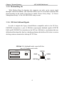
How To Use This Manual
ATC6430M Mainboard
HOW TO USE THIS MANUAL
This manual is written in a user-friendly style. It would be
advisable for users to read it in an orderly sequence :
1. For Hardware Information:
Read COMPONENT LOCATION DIAGRAM, Page A: QUICK JUMPER &
CONNECTOR SETTING, Page B: Slot 1 and CPU Installation, Page C:
CONNECTORS AND JUMPERS DESCRIPTION and Page D:List of Packaging.
2. For Mainboard and System Features:
Read “Chapter 1 System Features” , and you will find helpful information
on mainboard and system features. Especially, when you want to do some
feature setup, detailed instructions are provided therein to help you through.
3. For CPU, Memory and Drivers Installation:
Read “Chapter 2 Installation” for your CPU, memory and application drivers
installation. Detailed instructions are provided to guide all kinds of users.
4. For BIOS Update and Setup:
Read “Chapter 3 Award BIOS Setup” for updating your mainboard BIOS and
setting up your BIOS Configuration.
5. For other Technical Support:
Read “APPENDIX A”, fill and send the Request Form to your dealer for other
technical support.
The default settings on a mainboard is not necessarily what user expects. A
user-friendly manual would be the handiest assistant to help change the on-board
configuration or default setting. In case this manual cannot solve all your problems,
please ask your dealer for help and be sure the warranty on your system is still valid.
REMARK: Intel® is a registered trademark of Intel Corporation.
All other brands and product names are registered trademarks of their respective companies
ATC6430M Mainboard
Contents
CONTENTS
QUICK JUMPER & CONNECTOR SETTING..........................A
SLOT 1 AND PENTIUM II/III INSTALLATION...................B
CONNECTORS AND JUMPERS DESCRIPTION....................C
CHECKLIST OF PACKAGING................................................D
HOW TO USE THIS MANUAL
TABLE OF CONTENTS
CHAPTER 1
System Features......................................................1
1-1 Introduction.................................................................... .......... 1
1-2 System Specifications ..................................................... ...........2
1-3 Features Highlight...................................................................... ...3
1-3-1 Add-on Features for VGA in Intel 810.................................4
1-3-2 Add-on Features for Audio...................................................4
1-3-3 AMR and AC'97 CODEC Controller...................................5
1-3-4 Software Power Off Control.................................................5
1-3-5 Modem Ring On...................................................................6
1-3-6 SB-Link Sideband Signal.....................................................6
1-3-7 Ultra DMA 66 Cable(Optional)............................................7
1-3-8 Wake-On-LAN......................................................................8
CHAPTER 2
Installation ..................................................................9
2-1 Installation Procedure .................................................... .............9
2-2 CPU Installation.............................................................. .............10
2-3 System Memory Installation ............................................ .............11
2-4 Intel 810 Driver Installation.............................................. .............12
2-5 VGA Driver Installation................................................... .............12
2-6 Sound Driver Installation................................................. .............12
CHAPTER 3
Award BIOS Setup...................................................13
3-1 Update BIOS Procedure...... ........................................... .............14
3-2 System BIOS Configuration Setup .................................. .............16
3-2-1 Standard CMOS Features......................................................................18
3-2-2 Advanced BIOS Features.......................................................................21
3-2-3 Advanced Chipset Features...................................................................24
3-2-4 Integrated Peripherals............................................................................26
Contents
ATC6430 Mainboard
3-2-5 Power Management Setup......................................................................27
3-2-6 PNP/PCI Configuration..........................................................................31
3-2-7 PC Health Status ...................................................................................33
3-2-8 Frequency / Voltage Control...................................................................34
3-2-9Load Fail-Safe Defaults...........................................................................35
3-2-10 Load Optimized Defaults.................... ..................................................35
3-2-11SupervisorPassword/User Password......................................................35
3-2-12Save & Exit Setup.............................................................. ...................35
3-2-13Exit without Saving................................................................. ...............35
Appendix A Technical Support Request Form
ATC6430M Mainboard
Chapter 1 System Features
CHAPTER 1
System Features
1-1 Introduction
6430M mainboard is designed to run with Intel 810 chipset to enhance the
performance and extraordinary value of the Intel CeleronTM processor-powered
PC. On the other hand, it is mounted with both Slot 1 and Socket 370 connector for
users to make their CPU choice. It supports 66MHz, 100MHz and 133MHz Host
Bus Intel PPGA CeleronTM CPUs. To enhance its peripheral support, 5 PCI slots
are mounted on board, with an optional ISA slot to meet some exceptional users’
requirements. In addition to the incorporated VGA in Intel 810, its wide and
inclusive add-on features are described one by one in later part of this chapter.
Before that, let us see some architectural features of Intel 810.
Chipset Combination
FW82810DC100 / FW82810E
+ FW82801AA
With 4MB Display cache
Yes
Supporting UDMA 66
Yes
Shared
Memory
installing VGA driver
After
7MB
Users should check with your dealer for the right chipset type on your mainboard.
1
Chapter 1 System Features
ATC 6430M Mainboard
1-2 System Specifications of 6430M Mainboard
: CPU Support:
u Single CPU, with both Slot 1 and PPGA Socket 370 on board for choice.
u Supports CPU Clock 66MHz, 100MHz and 133MHz (133MHz support “Slot
1” socket only). CPU Clock Ratios from 3.0x to 8.0x (step 0.5x).
u Supports CPUs : Pentium II 233MHz~450MHz, Celeron 300MHz~500MHz,
and Pentium III 450MHz~650MHz.
u CPU Core Voltage 1.30V~2.05V (step 0.05V), and 2.1V~3.5V (Step 0.1V);
CPU~I/O Voltage 3.3V.
u Built-in Switching Voltage Regulator, supporting Vcore autodetection.
: Memory Support:
u Two DIMM sockets on board supporting up to 512MB SDRAM.
u PC-66 / PC-100 compatible.
: I/O System
u On-board Intel 810 Chipset for I/O Control:
FW82810DC100 / FW82810E + FW82801AA.
u Bus Frequency 66MHz/100MHz
u 5 PCI slots on board, compliant with version 2.2 PCI Local Bus spec.
u One Optional ISA slot.
u One AMR (Audio, Modem Riser) slot on board.
u Dual Master IDE connectors, supporting UDMA33/66 for 4 IDE devices such
as high capacity HDD, CD-ROM, LS-120 and tape backup etc.
u Two USB connectors in stack supporting up to 127 USB devices.
u PS/2 Keyboad and PS/2 Mouse connectors.
u One Infrared (IrDA TX/DX) connector.
u One FDD port supporting two Floppy drives of : 1.2MB / 1.44MB / 2.88MB.
u One parallel port for SSP/EPP/ECP mode printer.
u Two 16550A Fast UART compatible connectors for serial and VGA port.
u One Game /Midi port and 3 Audio Jacks for Speak-out, Line-in and
Microphone-in.
u One SB-Link Connector for Sound Card and PCI connection.
2
ATC6430M Mainboard
Chapter 1 System Features
: BIOS Support:
u Built-in VGA BIOS in Intel 810; and built-in Keyboard BIOS;.
u AWARD BIOS in Intel 810, providing CMOS Setup Utilities:
- Standard CMOS Features Setup for Date, Drives and VGA ;
- Advanced BIOS Features Setup for CPU Cache, Self Test, Boot Device,
Typematic Rate , and Security Options etc.;
- Advanced Chipset Features Setup for SDRAM CAS, RAS, System BIOS
Cacheable, and Video BIOS Cacheable etc.;
- Integrated Peripherals Setup for IDE Mode, USB, Audio, and Modem etc.;
- Power Management Setup on Video, HDD, CPU etc.;
- PnP/PCI Configurations Setup for PnP, Reset, Resources etc.;
- PC Health Status Control and Setup;
- Frequency / Voltage Control on CPU, SDRAM, PCI & SSC etc.;
- Load Fail-Safe Defaults;
- Load Optimized Defaults;
- Set Supervisor/User Password;
: Board Dimension :308mm x 202mm, in ATX form Factor. with one ATX Power
Connector.
3
Chapter 1 System Features
ATC 6430M Mainboard
1-3 Features Highlight
1-3-1 Add-on Features for VGA in Intel 810:
: Integrated Graphics Controller
u 3D Hyper Pipelined Architecture.
u Full 2D H/W Acceleration.
u Motion Video Acceleration.
: 3D Graphics Visual Enhancements
u Flat & Gouraud Shading.
u Mip Maps with Bilinear and Anisotropic Filtering.
u Fogging Atmospheric Effects.
u Z Buffering.
u 3D Pipe 2D Clipping.
u Backface Culling.
: 3D Graphics Texturing Enhancements
u Per Pixel Perspective Correction Texture Mapping.
u Texture Compositing.
u Texture Color Keying/Chroma Keying.
u Integrated 24-bit 230MHz RAMDAC.
: 2D Graphics
u Up to 1600 x 1200 in 8-bit Color at 85 Hz Refresh.
u Hardware Accelerated Functions.
: H/W Motion Compensation Assistance for S/W MPEG2 Decode
u Software DVD at 30fps.
u H/W Overlay Engine with Bilinear Filtering.
1-3-2 Add-on Features for Audio:
: Intel 810 ICH with built-in AC’97 controller.
: Supporting HRTF-based 3D positional audio, A3D, Q3D, wavetable, and 3D
surround sound.
Note: If you want to enable the onboard AC’97 CODEC, you need to set JP9 pin
2-3 closed. But in this way, the AMR slot will only accept a riser board with
Modem CODEC and cannot accept another Audio Riser.
4
ATC6430M Mainboard
1-3-3
Chapter 1 System Features
AMR and AC’97 CODEC Controller
AMR slot and AC’97 CODEC are integrated into the Mainboard to enable audio and
modem playback.
AMR (Audio/Modem Riser) slot is mounted on board to connect riser board with
Audio and/or Modem CODEC (AMC/AC/MC Adapters). The AMR specification
developed by Intel provides a mechanism for AC’97 codes to be on a riser card.
To enable the onboard AC’97 CODEC, set JP9 pin 2-3 closed. And in such way,
you can further plug a riser board with Modem CODEC to the AMR slot. Otherwise,
disabling onboard AC’97 CODEC by setting JP9 1-2 closed, you can plug a riser
board with Audio/Modem CODEC to the AMR slot.
See Page A for AMR location on 6430M Mainboard.
1-3-4 Software Power Off Control
This mainboard supports Software Power Off Control feature through the SMM code
in the BIOS under Windows 95/98, and MS-DOS operation system environment.
First, you should connect the power switch cable to the connector “PS-ON” on the
mainboard. In the BIOS screen of POWER MANAGEMENT SETUP’, choose “User
Define” (or “Min. Power Saving” or “Max. Power Saving”) in ‘Power Management’.
In Windows 95/98, if you want to power off the system, you just need to choose
“shutdown the computer?” in the “Shut Down Windows” of Windows 95/98. Then the
system power will be off directly, and stay at the stand-by status. If you want to restart
the system, just press the power switch button..
Note : If you are going to leave your system idle for several days, we suggest you
use hardware power off to shut down your system.
Status
Software power off control
APM mode
System running
Power LED Light
Light off
Light on
Light on
Turbo LED Light
Light off
Light on
Light on
To locate “PS-ON” header, please see “Page A Quick Jumper & Connector Setting”.
5
Chapter 1 System Features
ATC 6430M Mainboard
1-3-5 Modem Ring On
With Modem Ring On function, the computer can wake up by remote signal
through a connected modem. This function enables users to access their computer data
from anywhere in the world. Users have to enable “Power On by Ring” in “Power
Management Setup” of the AWARD BIOS setup screens.
1-3-6 SB-Link Sideband Signals
In order to migrate the legacy Sound Blaster compatible audio to the PCI bus,
EMU8008 incorporates a pair of SB-Link request/grant sideband signals (PCPCIR
EQN and PCPCIGNTN) to interface to the PCI bus. SB-Link is a mechanism that was
defined and developed by Intel as a docking solution which allows ISA slots to exist in
docking stations connected to desktop PC PCI bus.
SB-Link 2x3 sideband header, sound will also
has a 2x3 header and a cable.
PCI 5
REQ#
SB Link
PCI 4
6
GND
SIRQ
GNT#A
GND
ATC6430M Mainboard
Chapter 1 System Features
1-3-7 Ultra DMA 66 Cable (optional)
Ultra DMA 66 cable (40-pin connector & 80-line cable) is packaged while utilizing
FW82801AA chip which supports both UDMA 33 & UDMA 66 on the mainboard. In
other words, Ultra DMA 33 cable is only used with FW82801AB chip And the Ultra
DMA 66 color coded connectors are shown as bellow:
Blue to Mainboard
Grey to Slave
IDE Peripheral
Black to
Master
IDE Peripheral
1-3-8 Wake-On-LAN
The remote Wake-On-LAN (WOL) mode of operation is a mechanism that uses
Advanced Micro Device Magic Packet technology to power on a sleeping workstation
on the network. This mechanism is accomplished when the LAN card receives a
specific packet of information, called a Magic Packet, addressed to the node on the
network. For additional protection, Secure ON is an optional security feature that can
be added to the Magic Packet that requires a password to power on the sleeping
workstation. When LAN card is in remote Wake-On-LAN mode, main system power
can be shut down leaving power only for the LAN card and auxiliary power
recondition.
The LAN card performs no network activities while in the remote Wake-On-LAN
mode of operation. It only monitors the network for receipt of a Magic Packet. If a
Magic Packet is addressed to the LAN card on the network, the LAN card wake up the
system. If the Secure ON feature has been enabled, the password added to the Magic
Packet is also verified prior to waking up the system.
You should select two kinds of PCI Ethernet cards with WOL function. One is
Intel and the other is with PME signal supporting. And you can set “PCI PME#
7
Chapter 1 System Features
ATC 6430M Mainboard
Function” enabled through “ Power Management Setup” from the BIOS setup screen.
Caution: For Wake-On-LAN, the +5V standby line for the power supply should be
capable of delivering +5V ± 5% at 720mA. Failure to provide adequate standby current
when implementing Wake-On-LAN will damage the power supply.
WOL connector
+
8
6430M Mainboard
Chapter 2 Installation
CHAPTER 2
INSTALLATION
2-1 INSTALLATION PROCEDURE
Before installing the computer, please prepare all components such as CPU, DRAM;
peripherals such as hard drive, keyboard, CD-ROM and accessories such as cables.
Then, install the system as following:
-
Put CPU / heat sink (refer to CeleronTM CPU installation guide or see
the following setup chapter), and DRAM modules on the mainboard.
Plug add-on cards into PCI slots, if needed.
Connect cables to peripheral devices, especially for COM2 connector.
Make sure all components and devices are well connected, turn on the
power and setup System BIOS based on your configuration.
Install peripheral devices, add-on card drivers and test them.
If all of above procedures are running successfully, turn the power off
and screw the chassis cover to the chassis.
9
Chapter 2 Installation
6430M Mainboard
2-2 CPU INSTALLATION
This mainboard supports PPGA Socket 370 and Slot 1
processors.
The 6430M mainboard has built-in Switching Voltage Regulator to support CPU Vcore
autodetection. That is, It is smart enough to detect and recognize the CPU voltage,
clock, ratio and enables users to set up the CPU frequency from the BIOS Setup
Screen. Users can adjust the frequency through “Frequency / Voltage Control” of the
BIOS Setup Screen.
A. How to install CPUs for Socket 370:
1. Insert CPU Pin 1 to Pin 1 corner
of Socket 370 and lock it.
2. Insert Slot 1"Terminator Kit"
to Slot 1.
CPU for Socket 370
" Terminator Kit"
Pin 1
Corner
Locking
Lever
Socket 370
B. How to install CPU for Slot 1:
For Slot 1 CPU installation, please refer to “Page B Slot 1 installation” of this manual.
10
6430M Mainboard
Chapter 2 Installation
2-3 SYSTEM MEMORY INSTALLATION
6430M mainboard provides two 3.3V 168-pin DIMM sockets for system memory
expansion from 8MB to 512MB SDRAM. These two DIMMs are arranged to two
banks, please refer to page A.
Bank/DIMM
PC-100 Memory Module
Bank0/DIMM1
8/16/32/64/128/256MB
Bank1/DIMM2
8/16/32/64/128/256MB
Total System Memory
Total Memory
8MB~256MB
8MB~256MB
8MB~512MB
DIMM type, Size, parity supported:
6
6
6
6
PC-66/100 or higher performance memory module.
Both parity or non-parity are available.
3.3V, single/double-side.
8/16/32/64/128/256Mbytes.
u For either 66MHz , 100MHzand 133MHz host bus CPUs, please use 10ns or faster
and PC-100 compliant modules .
11
Chapter 2 Installation
6430M Mainboard
2-4 INTEL 810 DRIVER INSTALLATION
Ø INF Files for Windows 95/98 :
1. Start Windows 95/98.
2. Put the All-In-One CD into your CD-ROM drive.
3. Choose Intel 810/820 Inf Files on the Autorun main menu.
4. Then follow the instruction on the screen.
(INF Files that enable the Intel 810/820 Chipsets to be recognized by
listed operating systems.)
2-5 VGA DRIVER INSTALLATION
Install Intel 810 AGP Driver For Win95/98/NT
1. Start Windows 95/98/NT.
2. Put the All-In-One CD into your CD-ROM drive.
3. Choose Intel 810 AGP Driver on the Autorun main menu.
4. Press Next to install the driver.
5. Follow the instructions on the screen to complete the installation.
2-6 SOUND DRIVER INSTALLATION
Install Sound Driver For Win95/98/NT
1. Start Windows 95/98/NT.
2. Put the All-In-One CD into your CD-ROM drive.
3. Choose Audio Device Driver on the Autorun main menu.
4. Follow the instructions on the screen to finish the installation.
(Please refer to readme.doc file to get more detailed information.)
Install YAMAHA Software Synthesizer For Win95/98/NT
1. Start Windows 95/98/NT.
2. Put the All-In-One CD into your CD-ROM drive.
3. Choose YAMAHA Software Synthesizer on the Autorun main menu.
4. Follow the instructions on the screen to finish the installation.
(Please refer to readme.doc file to get more detailed information.)
Note : the sound driver is not supported under DOS operating system.
12
ATC6430M Mainboard
Chapter 3 Award BIOS Setup
CHAPTER 3
AWARD BIOS SETUP
Award BIOS manufacturer provides access to the system BIOS through the hardware
and software on mainboard. The hardware consists of a Flash ROM (4MB in 6430M
mainboard) and the software is a group of programs that are installed in the ROMBIOS
along with all the other data that should be included into the BIOS.
After the BIOS is updated, if you want to clear the old setup data stored in the CMOS,
then you can reset CMOS as follow.
NOTE : In case CMOS should be reset,first unplug the power cord, then set Jumper
8 2-3 closed for at least 5 seconds, reset JP8 1-2 closed so as to return to normal
position and plug the power cord again.
JP8
1-2
2-3
Normal
Reset CMOS
123
JP8
+
PCI 1 Slot
13
Chapter 3 Award BIOS Setup
ATC6430M Mainboard
3-1 UPDATE BIOS PROCEDURE
3-1-1 BIOS Update:
If the BIOS needs to be updated, you can get a CD with the updated BIOS utility in the
package. The CD includes :
“awdflash.exe” -- BIOS update utility program
“awdflash.doc”
The update procedure is as following:
1. Boot the system to DOS mode in a normal manner.
2. Insert the updated CD to drive D (or E).
3. Change working directory to CD-ROM drive, D or E, which contains the update
BIOS CD. -- Type “d:\” or “e: \”, then press “ENTER”.
4. Type “cd flash”, then press “ENTER”.
5. Type “awdflash”, then press “ENTER”-- for running the BIOS update utility.
6. Type “(update BIOS file name with version number).bin”, ENTER.
7. If you do not want to save the old BIOS, type “N” when the screen displays the
message : " Do you want to save BIOS (Y/N) ?".
8. Type “Y“ when the screen shows the message : " Are you sure to program
(Y/N) ?".
9. Follow instructions displayed on the screen. DO NOT remove the update BIOS
CD from the CD-ROM drive nor turn the system power off until the BIOS update
is completed.
10. Turn the power off. Clear the data in CMOS according to the procedure described
in the previous page.
11. Turn the system power on and test that your system is working properly.
14
ATC6430M Mainboard
Chapter 3 Award BIOS Setup
3-1-2 UPDATE MICROCODE API
Intel also provides MICROCODE API (Applications Programming Interface) for
mainboard user to update data block in BIOS quickly and easily. (You can find this
utility in the All-In-One CD in the mainboard package).
The BIOS code on the mainboards contains data that is specific to each silicon
stepping of the processor. Integrators must ensure that this BIOS stepping data
matches the used processor stepping. When the BIOS does not contain stepping data
that matches the processor stepping, integrators must update the data in the BIOS
before shipping the system. Historically, the systems have been updated by replacing
the entire BIOS with a new revision of BIOS that contains the correct stepping data.
Intel’s BIOS update API allows just the stepping data within the BIOS to be
updated as needed. Mainboards that contain a BIOS with the Intel-defined BIOS
update API can be quickly and easily updated, if required, without obtaining a
complete BIOS upgrade. Using this utility, integrators can easily verify that the correct
stepping data is present in all mainboards. However, if the stepping data requires to be
updated, the mainboard BIOS must contain the Intel-defined BIOS update API,
otherwise a complete BIOS upgrade is required from the mainboard vendor.
Since API program can only be executed under DOS Real Mode, you must enter
Real Mode first and load the API program to Drive C.
To load the program to C by following steps:
(1) Type “ md c:\ api ” and press Enter. Directory “api” is made in Drive C now.
(2) Insert the Driver/Utility CD into CD ROM Drive E.
(3) Then type “ copy e:\api\*.* c:\api ” and press Enter.
(API program is loaded to Drive C now.)
(4) Type “ C:\ api \checkup ” to execute this program.
The main menu should now be displayed with the following four options :
1) Check and load update
2) Specify stepping data file [current : pep.pdb]
3) Help
4) Quit without loading update
Select 1 to know the stepping filename, select 2 to load right patch code, then
select 1 to update proper patch code. Now, the screen will show the message “please
remove the CD from CD-ROM drive”. Then cold boot (mechanical power off) system
to continue. For more information, please refer to “CHECKUP.HLP“ file.
15
Chapter 3 Award BIOS Setup
ATC6430M Mainboard
3-2 SYSTEM BIOS CONFIGURATION SETUP
The following pages explain how to set up the BIOS configuration under the
Award BIOS. The SETUP program is stored in the Read-Only-Memory (ROM) on the
mainboard. To do the SETUP procedure, press the <Del> key when the system is
booting up. The following main menu will appear. Please select " STANDARD CMOS
FEATURE" to enter the next screen.
CMOS Setup Utility - Copyright ( C ) 1984-1998
Standard CMOS Feature
Frequency/Voltage Control
Advanced BIOS Feature
Load Fail-Safe Defaults
Advanced Chipset Feature
Load Optimized Defaults
Integrated Peripherals
Set Supervisor Password
Power Management Setup
Set User Password
PnP/PCI Configurations
Save & Exit Setup
PC Health Status
Exit Without Saving
↑ ↓ ← → : Select Item
Esc : Quit
F10 : Save & Exit Setup
Time, Date, Hard Disk Type….
The section at the bottom of the main menu explains how to control this screen.
upper section displays the items highlighted in the list.
16
The
ATC6430M Mainboard
Chapter 3 Award BIOS Setup
Control Key Description
UP ARROW
DOWN ARROW
LEFT ARROW
RIGHT ARROW
Esc KEY
Esc
PgUp KEY
PgDn KEY
F1 KEY
F5 KEY
F6 KEY
F7 KEY
F10 KEY
Help
Old Value
Load Fail-Safe
Defaults
Load Optimized
Defaults
Save & Exit
Setup
Move to the previous item
Move to the next item
Move to the item on the left
Move to the item on the right
Main Menu : Quit without saving changes
Setup menu : Exit current page and return to
main menu
Increase the numeric value or make changes
Decrease the numeric value or make changes
General help
Restore the pervious CMOS value from
CMOS
Load the fail-safe default CMOS value from
BIOS default table
Load the optimized default
Save all the CMOS changes and Exit setup,
only for Main Menu
17
Chapter 3 Award BIOS Setup
ATC6430M Mainboard
3-2-1 STANDARD CMOS FEATURES
This screen records some basic hardware
information, and sets the system clock and error handling. These records can be lost or corrupted if
the on-board battery has failed or is weak.
CMOS Setup Utility – Copyright © 1984-1998 Award Software
Standard CMOS Features
Date:
Time:
Ø
Ø
Ø
Ø
IDE
IDE
IDE
IDE
Primary Master
Primary Slave
Secondary Master
Secondary Slave
Mon, Apr 26 1999
16:19:20
Press Enter
Press Enter
Press Enter
Press Enter
Item Help
_____________________
None
Menu Level
Ø
None
None
Change the day, month,
None
year and century
Drive A
1.44M, 3.5 in.
Drive B
None
Floppy 3 mode support Disabled
Video
Halt On
EGA/VGA
All Errors
Based Memory
Extended Memory
Total Memory
640K
64512K
65536K
↑↓←→Move Enter: Select +/-/PU/PD: Value F10:Save ESC: Exit F1:General Help
F5:Previous Values
F6:Fail-safe defaults
F7:Optimized Defaults
Date
day
date
month
year
. Allows user to change the day, month, year and century, with Y2K support.
The day, from Sun to Sat, automatically changes when you set the date.
The date, from 1 to 31
The month, Jan. through Dec.
The year, from 1900 to 2099
Time The time format is <hour><minute><second>. , allowing user to set the internal
clock.
18
ATC6430M Mainboard
Chapter 3 Award BIOS Setup
IDE Primary Master; Primary Slave Secondary Master; Secondary Slave
Press Enter to enter next page for detailed hard drive settings:
CMOS Setup Utility – Copyright © 1984-1998 Award Software
IDE Primary Master
IDE HDD Auto-Detection
Press Enter
Item Help
Menu Level
IDE Primary Master
Capacity
Access Mode
Cylinder
Head
Precomp
Landing Zone
Sector
Auto
2557 MB
Auto
4956
16
0
4955
63
ØØ
To auto-detect the
HDD size, head..
on this channel
↑↓←→Move Enter: Select +/-/PU/PD: Value F10:Save ESC: Exit F1:General Help
F5:Previous Values
F6:Fail-safe defaults
F7:Optimized Defaults
IDE HDD Auto-Detection Press Enter to auto-detect the HDD. If detection is
successful, it fills the remaining fields on this menu.
IDE Primary Master If you select ‘Auto’, the BIOS will detect the HDD &
CD-ROM Drive automatically at the POST stage and show the IDE for HDD &
CD-ROM Drive. If you select ‘manual’, please contact your hard disk vendor or
dealer to get the information listed below. Then enter the figure directly and press
<Enter>.
The following options are selectable only if the IDE Primary Master item is set
to “Manual”.
Cylinder
number of cylinders
Head
number of read/write heads
Precomp
write precomp
Landing Zone
landing zone
Sector
number of sectors per track
Capacity Displays your disk drive size.
Access Mode Choose the access mode for the hard disk. The choices: Normal,
LBA, Large, Auto.
19
Chapter 3 Award BIOS Setup
ATC6430M Mainboard
Drive A, Drive B This category identifies the types of floppy disk drive A or drive B
that have been installed in the computer.
None
No floppy drive installed
360K, 5.25 in 5.25“ PC-type 360KB capacity
1.2M, 5.25 in 5.25“ AT-type 1.2MB capacity
720K, 3.5 in
3.5“ double-side 720KB capacity
1.44M, 3.5 in 3.5“ double-side 1.44MB capacity
2.88M, 3.5 in 3.5“ double-side 2.88MB capacity
Floppy 3 Mode Support This is the Japanese standard floppy drive. This standard
stores 1.2MB in a 3.5” diskette.
Video
To selects the type of primary video adapter used for the system monitor.
EGA/VGA Enhanced Graphics Adapter/Video Graphics Array. For EGA, VGA,
SEGA, SVGA or PGA monitor adapters
CGA 40
Color Graphics Adapters, power up in 40 column mode
CGA 80
Color Graphics Adapters, power up in 80 column mode
MONO
Monochrome adapter, includes high resolution monochrome adapters
Halt On This category determines whether the computer will stop if an error is
detected during power up.
No errors The system boot will not be stopped for any error that may be detected.
All errors When the BIOS detects a non-fatal error, the system will be stopped
and you will be prompted.
All, But
The system boot will not stop for a keyboard error. It will stop for all
Keyboard other errors.
All, But
The system boot will not stop for a floppy drive error. It will stop for all
Diskette
other errors.
All, But
The system boot will not stop for a floppy drive or keyboard error. It
Disk/Key will stop for all other errors.
Memory
To display what is detected by POST (Power On Self Test) of the BIOS.
Base Memory The POST will determine the amount of base (or conventional)
memory installed in the system. The value of the base memory is typically 512K or
640K based on the memory installed on the motherboard.
Extended Memory How much extended memory is present during the POST. This is
the amount of memory located above 1MB in the CPU‘s memory address map.
Total Memory Displays the total memory available in the system.
20
ATC6430M Mainboard
Chapter 3 Award BIOS Setup
3-2-2 ADVANCED BIOS FEATURES
This screen is a list of system configuration
options. Some of them are defaults required by the mainboard’s design, others depend on the features
of your system.
CMOS Setup Utility – Copyright © 1984 – 1998 Award Software
Advanced BIOS Features
Virus Warning
Disabled
CPU L1 Cache
Enabled
CPU L2 Cache
Enabled
CPU L2 Cache ECC Checking
Enabled
xProcessor Number Feature
Quick Power On Self Test
First Boot device
Second Boot device
Third Boot device
Boot other device
Swap Floppy Drive
Boot Up Floppy Seek
Boot Up NumLock Status
Gate A20 Option
Typematic Rate Setting
xTypematic Rate (Chars/Sec)
xTypematic Delay (Msec)
Security Option
OS Select For DRAM > 64MB
HDD S.M.A.R.T. Capability
Report No FDD for Win 95
N/A
Enabled
Floppy
HDD-0
SCSI
Enabled
Disabled
Enabled
On
Fast
Disabled
6
250
Setup
Non-OS2
Disabled
Item Help
______________________
_
Menu Level
Ø
Allows you to choose the
VIRUS warning feature
for IDE Hard Disk boot
sector protection. If
this function is enabled
and someone attempt to
write data into this
area, BIOS will show a
warning message on
screen and alarm beep
No
↑↓←→Move Enter: Select +/-/PU/PD: Value F10:Save ESC: Exit F1:General Help
F5:Previous Values
F6:Fail-safe defaults
F7:Optimized Defaults
Virus Warning Allows user to choose the VIRUS warning feature for IDE Hard
Disk boot sector protection. If this function is enabled and someone attempts to write
data into this area, BIOS will show a warning message on screen and alarm beep.
! WARNING !
Disk boot sector is to be modified
Type ‘Y’ to accept write or ‘N’ to abort write
Award Software, Inc.
CPU L1 Cache, L2 Cache These two categories speed up memory access. However,
it depends on CPU design. The default value is ‘Enabled‘.
21
Chapter 3 Award BIOS Setup
ATC6430M Mainboard
CPU L2 Cache ECC Checking If Enabled, this function will do ECC check to CPU
L2 Cache automatically.
Quick Power On Self Test This category speeds up Power On Self Test while
booting. If “Enabled”, BIOS will skip some items under check by POST.
First Boot Device, Second Boot Device, Third Boot Device, Boot Other Device Allows
user to select the Boot Device Priority. The choices: Floppy, LS/ZIP/, HDD, SCSI,
CDROM, Disabled.
Swap Floppy Drive If the system has two floppy drives, choose “Enabled” to assign
the physical drive B to logical drive A and vice-versa.
Boot Up Floppy Seek
have 40 or 80 tracks.
“Enabled” will test floppy drives and determine whether they
Boot Up NumLock Status This allows you to determine the default state of the
numeric keypad. By default, the system boots up with NumLock on.
On
Keypad is for numeric keys
Off
Keypad is for arrow keys
Gate A20 Option This entry allows you to select how the gate A20 is handled. The
gate A20 is a device used to address memory above 1 MB. If “Normal”, keyboard is
controlled by a pin in keyboard controller. If “Fast”, it is controlled by chipset.
Typematic Rate Setting Keystrokes repeat at a rate determined by the keyboard
controller. When “Enabled”, the typematic rate and typematic delay can be selected.
Typematic Rate (Chars/Sec) When the typematic rate is enabled, this item will
appear to allow you to select the key repeat rate. 6 means 6 characters per second.
Typematic Delay (Msec) When the typematic rate is enabled, this item will appear to
allow you to set the delay time before key strokes begin to repeat. 250: 250 msec
(500,750,1000)
Security Option This category allows you to limit access to the system and Setup,
or just to Setup. Options:
System Password is then required every time the system boots.
Setup
The system will boot without password, but access to Setup requires
correct password.
22
ATC6430M Mainboard
Chapter 3 Award BIOS Setup
OS Select for DRAM > 64MB This item allows you to access the memory that is over
64MB in OS/2. The choice : Non-OS2, OS2
HDD S.M.A.R.T. Capability
Select Enabled if your Hard disk supports
S.M.A.R.T.(Safe-Monitoring Analysis and Reporting Technology) function.
Report No FDD For WIN 95 Set this item to Yes, BIOS will report FDD to Win95. If
in standard CMOS setup, set Drive A to none and set this item to “Yes”, inside Win95,
My Computer and File manager Disk(A:) will show Removable Disk (A:).
23
Chapter 3 Award BIOS Setup
ATC6430M Mainboard
3-2-3 ADVANCED CHIPSET FEATURES
This screen controls the setting for the
chipset on the mainboard. This chipset manages bus speeds and access to system memory resources.
CMOS Setup Utility – Copyright © 1984 – 1998 Award Software
Advanced Chipset Features
SDRAM CAS Latency Time
3
Item Help
SDRAM Cycle Time Tras/Trc
6/8
____________________
SDRAM RAS-to-CAS Delay
3
_
SDRAM RAS Precharge Time
3
System BIOS Cacheable
Enabled
Menu Level
Ø
Video BIOS Cacheable
Enabled
Memory Hole At 15M-16M
Disabled
Delay Transaction
Enabled
On-Chip Video Window Size
64MB
* Onboard Display Cache Setting *
CAS# Latency
3
Paging Mode Control
Close
RAS-to-CAS Override
By CAS#
LT
RAS# Timing
Slow
RAS# Precharge Timing
Slow
↑↓←→Move Enter: Select +/-/PU/PD: Value F10:Save ESC: Exit F1:General Help
F5:Previous Values
F6:Fail-safe defaults
F7:Optimized Defaults
24
ATC6430M Mainboard
Chapter 3 Award BIOS Setup
SDRAM CAS Latency Time When synchronous DRAM is installed, the number of
clock cycles of CAS latency depends on the DRAM timing. The choices: 2,3. “2”
gives faster performance and “3” gives more stable performance.
SDRAM Cycle Time Tras/Trc Select the number of SCLKs for an access cycle.
“5/7” gives faster performance and “6/8” gives more stable performance.
SDRAM RAS-to-CAS Delay This field lets you insert a timing delay between the
CAS and RAS strobe signals, used when DRAM is written to, read from, or
refreshed. “2” gives faster performance and “3” gives more stable performance. This
field applies only when synchronous DRAM is installed in the system.
SDRAM RAS Prechage Time If an insufficient number of cycles is allowed for the
RAS to accumulate its charge before DRAM refresh, the refresh may be incomplete
and the DRAM may fail to retain data. This field applies only when synchronous
DRAM is installed in the system.
System BIOS Cacheable Selecting Enabled allows the caching of the system BIOS
ROM area, resulting in better system performance. However, if any program writes to
this memory area, a system error may result.
Video BIOS Cacheable Selecting Enabled allows the caching of the video BIOS
ROM area, resulting in better system performance. However, if any program writes to
this memory area, a system error may result.
Memory Hole At 15M-16M Certain space in memory can be reserved for ICH/ICH0.
Delay Transaction This chipset has an embedded 32-bit posted write buffer to
support delay transactions cycles. Select Enabled to support compliance with PCI
specification version 2.1. The choice : Enabled, disabled space
On-chip Video Window Size Determine the size of memory space that can be
allocated for on-chip graphics device.
The following items are optional for onboard display cache setting:
CAS# Latency The number of clock cycles of CAS latency depends on the Display
Cache timing. The choices: 2,3. “2” gives faster performance and “3” gives more
stable performance.
Paging Mode Control
Close: the GMCH will precharge all during the service of a
25
Chapter 3 Award BIOS Setup
ATC6430M Mainboard
page miss. Open: it will precharge bank during the service of a page miss.
RAS-to-CAS Override By CAS# LT: the RAS-to-CAS delay timing will be the same
as item of CAS# Latency. Override: the value will be fixed in 2.
RAS# Timing This item controls the active time of RAS# and bank cycle time.
“Fast” gives faster performance and “Slow” gives more stable performance.
RAS# Precharge Timing If an insufficient number of cycles is allowed for the RAS
to accumulate its charge before DRAM refresh, the refresh may be incomplete and the
DRAM may fail to retain data. “Fast” gives faster performance and “Slow” gives more
stable performance.
26
ATC6430M Mainboard
Chapter 3 Award BIOS Setup
3-2-4 INTEGRATED PERIPHERALS
This section page includes all the items of
IDE hard drive and Programmed Input/Output features. See also Section “Chipset Features Setup”.
CMOS Setup Utility – Copyright © 1984 – 1998 Award Software
Integrated Peripherals
OnChip Primary PCI IDE
OnChip Secondary PCI IDE
IDE Primary Master PIO
IDE Primary Slave PIO
IDE Secondary Master PIO
IDE Secondary Slave PIO
IDE Primary Master UDMA
IDE Primary Slave UDMA
IDE Secondary Master UDMA
IDE Secondary Slave UDMA
USB Controller
USB Keyboard Support
Init Display First
AC97 Audio
AC97 Modem
IDE HDD Block Mode
Power On Function
xKB Power On Password
xHot Key Power On
Onboard FDC Controller
Onboard Serial Port 1
Onboard Serial Port 2
UART Mode Select
xUART Duplex Mode
Onboard Parallel Port
Parallel Port Mode
ECP Mode Use DMA
PWRON After PWR-Fail
Game Port Address
Midi Port Address
xMidi Port IRQ
CIR Port Address
xCIR Port IRQ
Enabled
Enabled
Auto
Auto
Auto
Auto
Auto
Auto
Auto
Auto
Enabled
Disabled
PCI Slot
Auto
Auto
Enabled
Button Only
Enter
Ctrl-F1
Enabled
3F8/IRQ4
2F8/IRQ3
Normal
Half
378/IRQ7
ECP
3
Off
201
Disabled
7
Disabled
Item Help
_____________________
_
Menu Level
Ø
If your IDE hard drive
supports block mode
select Enabled for
automatic detection of
the optimal number of
block read/write per
sector the drive can
support
11
↑↓←→ Move Enter: Select +/-/PU/PD: Value F10:Save ESC: Exit F1:General Help
F5:Previous Values
F6:Fail-safe defaults
F7:Optimized Defaults
On-Chip Primary PCI IDE; On-Chip Secondary PCI IDE This setup item allows you
to either enable or disable the primary/secondary controller. You might choose to disable
the controller if you want to add higher performance or specialized controller.
IDE Primary Master/Slave PIO IDE; Secondary Master/Slave PIO
PIO - Programmed Input/Output, it allows the BIOS to tell the controller what it wants
and then let the controller and the CPU to complete the task by themselves. This is
27
Chapter 3 Award BIOS Setup
ATC6430M Mainboard
simpler and faster. Your system supports five modes, 0 - 4, which primarily differ in
timing. When Auto is selected, the BIOS will select the best available mode.
IDE Primary Master/Slave UDMA; IDE Secondary Master/Slave UDMA Auto, will
support the Ultra DMA function. Disabled, will not support the Ultra DMA function.
USB Controller This item allows you to decide to enable/disable the USB controller.
USB Keyboard Support Enabled will support USB keyboard in Win95 2.1 and NT
5.0 or above operating system.
Init Display First This item allows you to decide to activate PCI VGA or on-chip
VGA first. The choice: PCI Slot, Onboard.
AC97 Audio; AC 97 Modem This item allows you to decide to enable/disable the
i810 chipset family to support AC97 Audio/Modem.
IDE HDD Block Mode This allows your HD controller to use the fast block mode to
transfer data to and from your HD drive.
Enabled
IDE controller uses block mode
Disabled
IDE controller uses standard mode
Power On Function This function supports 7 “Power On “ modes : Password,
Hot Key, Mouse Move, Mouse Click, Any Key, Button Only, and Keyboard 98.
Default is “Button Only”. If “Password” is chosen, the item “KB Power On
Password” will appear to ask you to enter password. If “Hot Key” is chosen, the
item “Hot Key Power On” will appear to ask you to pick the Hot Key.
On Board FDC Controller
controller.
This item will enable or disable the floppy disk
On Board Serial Port 1 User can select serial port IRQ. If set to Auto, system will
assign an IRQ for it. Note : set to Auto is not recommended.
On Board Serial Port 2 User can select serial port IRQ. If set to Auto, system will
assign an IRQ for it. Note : set to Auto is not recommended.
28
ATC6430M Mainboard
Chapter 3 Award BIOS Setup
UART Mode Select This lets you select the Infrared mode. Choices are IrDA,
ASKIR, Normal, and SCR. Only when you choose IrDA or ASKIR , the screen will
then show “UART2 Duplex Mode’ for you to choose “Full” or “Half”..
On Board Parallel Port Let user select IRQ for parallel port When Disabled, the
parallel port will be disabled.
Parallel Port Mode Let user select Parallel Port : SPP, EPP, ECP, ECP+EPP
ECP Mode Use DMA Select a DMA channel for the port. Choices are 3, 1.
PWRON After PWR-Fail
Allows you to choose “Off”, On, former-Status”.
Game Port Address; Midi Port Address The IO address of Game Port/Midi Port.
If Midi Port is fixed, the item “Midi Port IRQ” will appear for setting.
CIR Port Address Allows you to fix the Consumer Infrared Device Port Address.
If fixed, the item “CIR Port IRQ” will appear for setting.
29
Chapter 3 Award BIOS Setup
ATC6430M Mainboard
3-2-5 POWER MANAGEMENT SETUP
This screen controls the 'green' features
of this mainboard.
CMOS Setup Utility – Copyright © 1984 – 1998 Award Software
Power Management Setup
ACPI function
Power Management
Video Off Method
Video Off In Suspend
Suspend Type
MODEM Use IRQ
Suspend Mode
HDD Power Down
Soft-Off by PWRBTN
PCI PME# Function
Power On by Ring
CPU Thermal-Throttling
Resume by Alarm
Enabled
Item Help
User Define
____________________
DPMS
Yes
Menu Level
Ø
Stop Grant
3
Disabled
Disabled
Instant Off
Disabled
Enabled
50.0%
Disabled
** Reload Global Timer
Primary IDE 0
Primary IDE 1
Secondary IDE 0
Secondary IDE 1
FDD, COM, LPT Port
PCI PIRQ [A-D]#
Events **
Disabled
Disabled
Disabled
Disabled
Disabled
Disabled
↑↓←→Move Enter: Select +/-/PU/PD: Value F10:Save ESC: Exit F1:General Help
F5:Previous Values
F6:Fail-safe defaults
F7:Optimized Defaults
ACPI function This item is to set the ACPI ( Advanced Configuration Power
Interface ) function enabled or disabled.
Power Management This category allows you to select the type (or degree) of
power saving and is directly related to the following modes : Suspend; HDD Power
Down.
Disabled
No power management. It means all 4 modes are disabled.
Min. Power Minimum power management. Doze =1hr.; Standby=1hr.;
Saving
Suspend=1hr.; HDD Power Down=15min
Max. Power
Saving
User
Define
Maximum power management Doze=1min.; Standby=1min.;
Suspend=1min.;HDD Power Down=1min
Allows you to set each mode individually. When not disabled, each
of the ranges are from 1min. to 1hr. except for HDD Power Down
which ranges from 1 to 15min. and disable
30
ATC6430M Mainboard
Video Off Method
V/H SYNC
+ Blank
Blank Screen
DPMS
Chapter 3 Award BIOS Setup
This determines the manner in which the monitor is blanked.
This selection will cause the system to turn off the vertical and
horizontal sync. ports and write blanks to the video buffer.
This option only writes blanks to the video buffer.
Initial of “Display Power Management Signaling”.
Video off In Suspend This determines the manner in which the monitor is blanked.
Suspend Type
Select the suspend type.
Stop Grant
Only CPU enters sleeping mode
Full on Suspend Both CPU and chipset enter sleeping mode
MODEM Use IRQ This item determines the IRQ in which the MODEM can be used.
The choice : 3,4,5,7,9,10,11,NA.
Suspend Mode When enabled and after the set time of system inactivity, all devices
except the CPU will be shut off.
HDD Power Down When enabled and after the set time of system inactivity, the hard
disk drive will be powered down while all other devices remain active.
Soft-Off by PWR-BTTN Instant-off : When push the power button, the system
power will be off immediately. Delay 4 sec : when push the power button, it will enter
suspend mode. We need to push the power button and hold it for 4 seconds to turn
off the power.
PCI PME# Function With PCI card supporting PCI Power Management capability
and this item setting to Enabled, the system can be waked up by PCI card.
PowerOn by Ring Enabled: when system is in suspend mode, it can be waked up by
modem. Disabled: it cannot be waked up by modem.
Resume by Alarm When Enabled, two additional lines will be added to the
screen :Date (of Month) Alarm; Time (hh:mm:ss) Alarm to let user set the desired date
and time. After power off, the system will automatically power on at the specified date
and time.
Reload Global Timer Events When enabled, an event occurring on each device
listed below restarts the global time for Standby mode. IRQ [3-7, 9-15], NMI; Primary
IDE 0; Primary IDE 1; Secondary IDE0; Secondary IDE1; Floppy Disk; Serial Port;
Parallel Port.
31
Chapter 3 Award BIOS Setup
ATC6430M Mainboard
3-2-6 PNP/PCI CONFIGURATION
This screen configures the PCI Bus slots.
CMOS Setup Utility – Copyright © 1984-1998 Award Software
PnP/PCI Configurations
PNP OS Installed
Reset Configuration Data
No
Item Help
-------------------Disabled Menu Level
Ø
Resources Controlled By Auto
Select “Yes” if you are
Ø IRQ Resources
Press Enter using a Plug and Play OS.
Ø DMA Resources
Press Enter Select NO if you need the
Ø Memory Resources
Press
BIOS to confirm
Enter
non-boot device.
PCI/VGA Palette Snoop
Disabled
↑↓←→Move Enter: Select +/-/PU/PD: Value F10:Save ESC: Exit F1:General Help
F5:Previous Values
F6:Fail-safe defaults
F7:Optimized Defaults
PNP OS Installed Select “Yes” if you are using a Plug nad Play OS. Select “No” if
you need the BIOS to confirm non-boot device.
Reset Configuration Data This item allows you to determine whether to reset the
configuration data or not.
Resource Controlled by The Award Plug and Play BIOS has the capability to
automatically configure all of the boot and Plug & Play compatible devices. However,
this capability means absolutely nothing unless you are using a Plug and Play OS such
as Windows 95. Choices are Auto and Manual.
IRQ Resources; DMA Resources When resources are controlled manually, assign
each system interrupt/DMA channel a type, depending on the type of device using the
interrupt/DMA channel.
IRQ3/4/5/7/9/1011/12/14/15, DMA0/1/3/5/6/7 Assign to This item allows you to
determine the IRQ/DMA assigned to the ISA bus and is not available to any PCI slot.
Choices are Legacy ISA and PCI/ISA PnP.
Memory Resources “Memory Resources” has two events:
Resources Memory Base
N/A
32
ATC6430M Mainboard
Memory Resources
Chapter 3 Award BIOS Setup
Length
8K
33
Chapter 3 Award BIOS Setup
ATC6430M Mainboard
PCI/VGA Snoop It determines whether the MPEG ISA/VGA cards can work with
PCI/VGA or not.
Enabled
When PCI/VGA working with MPEG ISA/VGA Card
Disabled
When PCI/VGA not working with MPEG ISA/VGA Card
34
ATC6430M Mainboard
Chapter 3 Award BIOS Setup
3-2-7 PC Health Status
This screen shows your in-use PC Health Condition:
CMOS Setup Utility – Copyright © 1984-1998 Award Software
PC Health Status
Vcore
+2.5V
+3.3V
+5V
+12V
-12V
+1.8V
VTT(V)
Voltage Battery
CPU Temperature
System Temperature
CPU Fan Speed
Chassis Fan Speed
CPU Warning Temperature
Shutdown Temperature
Item Help
------------------Menu Level
Ø
700C/1580F
900C/1940F
↑↓←→ Move Enter: Select +/-/PU/PD: Value F10:Save ESC: Exit F1:General Help
F5:Previous Values
F6:Fail-safe defaults
F7:Optimized Defaults
Vcore---Chassis Fan Speed
CPU Warning Temperature
Shutdown Temperature
These items are to show the in-use PC conditions.
Default temperature is 700C/1580F.
Default temperature is 900C/1940F.
35
Chapter 3 Award BIOS Setup
ATC6430M Mainboard
3-2-8 FREQUENCY / VOLTAGE CONTROL
This screen controls the 'green'
features of this mainboard.
CMOS Setup Utility – Copyright © 1984-1998 Award Software
Frequency/Voltage Control
Auto Detect DIMM/PCI CLK Disabled
CPU/SDRAM/PCI Clock
& SSC Default
CPU Ratio
X 3
Item Help
------------------Menu Level
Ø
↑↓←→ Move Enter: Select +/-/PU/PD: Value F10:Save ESC: Exit F1:General Help
F5:Previous Values
F6:Fail-safe defaults
F7:Optimized Defaults
Auto Detect DIMM/PCI ClK If this item is enabled, the unused DIMM and PCI slot
clock will be disabled. If this item is disabled the unused DIMM and PCI slot will still
get the active clock signal.
CPU/SDRAM/PCI Clock & SSC Use this item to set CPU base clock frequency
and Spread Spectrum clocking function..
The optimized range of combinations are :
CPU
SDRAM
PCI
SSC
66~155MHz 100~155MHz
33~38MHz
On/Off
After you change the CPU Clock Frequency and the system can not start, please
do the following procedures:
1. Turn the system off firstly.
2. Turn on the system. Then press and hold the “ Insert ” key at boot.
3. Select the proper figure in the item of CPU/SDRAM/PCI Clock.
Save and Exit Setup.
CPU Ratio Use this item to set CPU ratio which includes x 3 x 3.5 x 4
x 5 x 5.5 x 6 x 6.5 x 7 x 7.5 and x 8.
36
x 4.5
ATC6430M Mainboard
Chapter 3 Award BIOS Setup
3-2-9 LOAD FAIL-SAFE DEFAULTS When your mainboard has problems and
needs to trouble shoot the system, you can use this function. The default values loaded
only affect the BIOS Features Setup, Chipset Features Setup, Power Management
Setup and PNP/PCI Configuration Setup. There is no effect on the Standard CMOS
Setup. To use this function, select it from main menu and press <Enter>. A line will
appear on the screen asking if you want to load the fail-safe default values. Press
<Yes> and <Enter> then the BIOS default values will be loaded.
3-2-10 LOAD OPTIMIZED DEFAULTS
This allows you to load optimal
settings which are stored in the BIOS ROM. The default values loaded only affect the
BIOS Features Setup, Chipset Features Setup, Power Management Setup and
PNP/PCI Configuration Setup. There is no effect on the Standard CMOS Setup. To
use this function, select it from main menu and press <Enter>. A line will appear on
the screen asking if you want to load the optimized default values. Press <Yes> and
<Enter> then the Setup default values will be loaded.
3-2-11 SUPERVISOR PASSWORD / USER PASSWORD This allows you to set
the password. The mainboard defaults with password disabled. If you set both
supervisor and user passwords, only the supervisor password allows you to enter
the BIOS SETUP program.
Enter/Change password : Enter the current password. And at the prompt, key-in your
new password (up to eight alphanumeric characters), then press <Enter>. At the next
prompt, confirm the new password by typing it again and press <Enter>.
Disable password : Press the <Enter> key instead of entering a new password when
the ‘Enter Password’ dialog box appears. A message will appear for confirming that
the password is disabled.
CAUTION: If you forget your password, you must clear CMOS first and restart
system so as to set up password again. See “Reset CMOS” on Page 12.
3-2-12 SAVE & EXIT SETUP
This allows you to save the new setting values
in the CMOS memory and continue with the booting process. If you select this item
and press 'Y', then these records will be saved in the CMOS memory on the
mainboard. It will be checked every time you turn your computer on.
3-2-13 EXIT WITHOUT SAVING This allows you to exit the BIOS setup utility
without recording any new values or changing old ones.
37