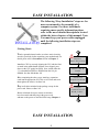
1
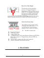
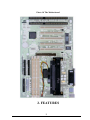
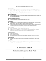
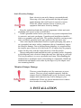
Advanced Pentium II Motherboard KR632 USER’S MANUAL Copyright 1997 GVC CORPORATION. ALL RIGHTS RESERVED. 1 NOTICE Rights: No part of this manual, including but not limited to the products and software described in it, may be reproduced, transmitted, transcribes, stored in a retrieval system, or translated in any form or by any means without the expressed written permission of GVC “Corporation or BCM Advanced Research, Inc. Products and corporate names appearing in this manual may or may not be registered trademarks or copyrights of their respective companies and are used only for identification or explanation purposes without intent to infringe. ¨ ¨ ¨ ¨ Intel, MMX and Pentium are registered trademarks of Intel Corporation. IBM and OS/2 are registered trademarks of International Business Machines. AMI is a registered trade mark of American Megatrends Inc.. Winbond is a registered trademark of Winbond Electronics Inc.. Responsibility: This manual is provided “As is” with no warranties of any kind, either expressed or implied, including, but not limited to the implied warranties or conditions of this product’s fitness for any particular purpose. In no event shall we be liable for any loss of profits, loss of business, loss of data, interruption of business, or indirect, special, incidental, or consequential damages of any kind, even the possibility of such damages arising from any defect or error in this manual or product. We reserve the right to modify and update the user manual without prior notice. 2 COMPLIANCE & CERTIFICATE ISO 9001 Certificate: This device was produced in our plant with advanced quality system certified by DNV QA Ltd. in according to ISO 9001. This Certificate is valid for : DESIGN & MANUFACTURE OF MOTHER BOARDS AND PERSONAL COMPUTERS. CE Declaration: CE marking is a visible declaration by the manufacturer or his authorized representatives that the electrical equipment to which it relates satisfies all the provisions of the 1994 Regulations. FCC Compliance: FCC stands for Federal Communications Commission. This product complies with FCC Rules Part 15 and has been tested, and complied with the EMI rules by a certified body. In normal operation, there shall be no harmful interference caused by this device nor shall this devise accept any interference received, including interference that may cause undesired operation of this product. Microsoft Windows Compliance: Microsoft, Windows NT, Windows, and the Windows Logo are registered trademarks of Microsoft Corporation. 3 EASY INSTALLATION The following “Easy Installation” steps are for users accustomed to the assembly of a computer system. For those individuals requiring more specific information please refer to the more detailed descriptions located within the latter chapters of this manual. Note: You must keep your power cable unplugged until the following installation steps are completed. Getting Start: Touch a grounded metal surface to release static electricity stored in your body before unpacking your motherboard. For details please refer to Precaution section in Chapter 3. Install the CPU by correctly aligning the CPU with the Slot 1 as noted in the motherboard diagram. Once aligned, press down on the CPU gently but firmly. Next, install either the 3.3 volt unbuffered EDO or SDRAM into the 168 pin DIMMs. See Sec. 3.2 & Sec. 3.3. After completing the above steps, install any expansion cards into the appropriate PCI, ISA or AGP slots and screw them tight to the chassis. See Sec. 3.4. Plug in all cables included in the package except for the power cord. Please see Sec. 3.5. Release Static Electricity Insert CPU & RAM Install All Expansion Slots Couple Connectors Of HDD, FDD… Please rechecked all steps to ensure no mistakes have been made and then plug in the power cord and turn on the power to enter the BIOS setup, Chapter 4. EASY INSTALLATION 4 CONTENTS 5 1. INTRODUCTION How To Use This Manual Check Your Device Items 2. Page8 Page8 FEATURES Photo Of The Motherboard Features Of The Motherboard 3. Page9 Page10 INSTALLATION Motherboard Layout & Main Parts Significant Parts List Precaution Before Start Page12 Page13 Page14 3.1 Slots And Connectors Page15 3.2 CPU Page16 3.3 System Memory ( DRAM ) 3.3.1 DIMM (Dual Inline Memory Module) 3.3.2 Installation Procedure 3.3.3 DIMM Combinations Page18 3.4 Expansion Slots Page20 Connectors Page21 3.5 3.5.1 Primary IDE Connector 3.5.2 Secondary IDE Connector 3.5.3 Floppy Drive Connector CONTENTS 3.5.1 3.5.2 3.5.3 3.5.4 Power Input Connector Front Panel Connectors Back Panel Connectors Additional Connectors 6 Ready To Turn On Power Page29 4. BIOS SETUP 4.1 How To Enter BIOS Setup 4.1.1 Setup Keys 4.1.2 In Case Of Problem Page31 4.2 BIOS Setup Main Menu Page33 4.2.1 MAIN MENU > STANDARD CMOS SETUP 4.2.2 MAIN MENU > ADVANCED CMOS SETUP 4.2.3 MAIN MENU > ADVANCED CHIPSET SETUP 4.2.4 MAIN MENU > POWER MANAGEMENT SETUP 4.2.5 MAIN MENU > PCI/PLUG AND PLAY SETUP 4.2.6 MAIN MENU > PERIPHERAL SETUP 4.2.7 MAIN MENU > CPU SPEED SETUP 4.2.8 MAIN MENU > AUTO-DETECT HARD DISKS 4.2.9 MAIN MENU > CHANGE SUPERVISOR PASSWORD 4.2.10 MAIN MENU > AUTO CONFIGURATION WITH OPTIMAL SETTING 4.2.11 MAIN MENU > SAVE SETTINGS AND EXIT 4.2.12 MAIN MENU > EXIT WITHOUT SAVING TECHNICAL SUPPORT Page55 1. INTRODUCTION 7 How To Use This Manual This manual provides information necessary for Original Equipment Manufactures (OEMs) and home users to build a PC-AT compatible system using the Pentium II AGP/PCI motherboard. Just follow the installation procedure presented on the EASY INSTALLATION Page and refer to the section number following each step if you require more detailed instructions. Check Your Device Items The standard package should contain following items marked with a “ü”, If you find any these items missing or damaged. Please contact your retailer. þ þ þ þ o o þ The KR632 motherboard Retention Mechanism 1 IDE ribbon cable 1 floppy ribbon cable 1 CD-ROM Diskette with system Hardware Monitor and PIIX4 Bus Master Driver inside or 1 Floppy Diskette with only PIIX4 bus Master Driver. Infrared (IrDA) module with ribbon cable (optional) Pentium II Retention Mechanism (optional) 2. FEATURES 8 Photo Of The Motherboard 2. FEATURES 9 Features Of The Motherboard The KR632 motherboard integrates the Pentium II microprocessor, memory, I/O and AGP (Accelerated Graphics Port) and is designed to fit into a standard ATX form factor chassis. Page 12 illustrate the Layout for the KR632 motherboard. Below lists the key features provided by this motherboard: Processor(+Cache) l Single slot-1 for Pentium II processor l Supports Pentium II processor speeds (233-333MHz) l 512KB second-level cache integrated into the Single Edge Pentium II Contact cartridge Jumperless Design l Using the onboard BIOS, jumpers settings are no longer needed. Chipset l 82440LX AGP/PCI/ISA Chipset. System Memory l Three 168-pin DIMM sockets l Minimum 8MB up to maximum 384 MB of unbuffered SDRAM or EDO RAM l ECC (Error Checking & Correction) or non-ECC memory support Graphics Support l Supports AGP (Accelerated Graphics Port) for increased performance of Graphic Displays, special 3D operations in multimedia, and higher speed to satisfy the users optical vision. l AGP Interface supports data transfers at 66 MHz (1x) or 133 MHz (2X) with full side-band signals. PCI Bus Master IDE Controller l Integrated PCI Bus Master IDE Controller Chip with Ultra-DMA33 capabilities. Up to four IDE devices can be supported using the two onboard IDE connectors. Also supported is PIO Modes 3&4, Bus Master IDE DMA Mode 2 and Enhanced IDE devices such as Tape Backup machines and CD-ROMs. Either the 5.25 inch or 3.5 inch (1.44MB or 2.88MB) floppy drives can be used without requiring an external card. Additionally, Floppy 3 mode (Japanese standard 3.5 inch disk drive, 1.2MB) and LS-120 floppy disk drives (3.5 inch disk drive: 120MB, 1.44MB, 720K) are also supported. 2. FEATURES 10 Features Of The Motherboard Integrated I/O l Winbond 977, supporting two async serial ports with high speed 16C550 and 16-byte FIFO. One Parallel port supporting EPP, ECP and Bi-directional modes. PS/2 keyboard port and mouse port. l (Optional) Infrared port module (IrDA) for wireless interface. Hardware Monitoring l (Optional) Onbaord LM78 / LM75 chip to monitor variable voltages used in system CPU fan speed, and temperature. External Communication Ports l Universal Serial Bus (USB), integrated with Core Logic. System BIOS l AMI BIOS based on 1MB Flash ROM. Enable IDE Auto-configuring, support ISA Plug & play, PC-97, Multi-Boot and PCI Add-In card auto-configuring. l Also it supports DMI, which allows hardware to communicate within a standard protocol creating a higher level of compatibility. (Requires DMI-enabled component.) Green Features l Power Management: APM 1.2, Meets EPA Mode 2.0. l Additionally, with support for ACPI (Advanced Configuration and Power Interface) feature, your system will become more wise in management of power. Additional features l Wake-On-Lan header l Smart soft power control l SB-LINK header to support legacy Sound Blaster compatible Audio to the PCI bus. Expansion Slots l Five PCI, Two ISA bus slots (one slot is shared) and One AGP slot for your variable usage. Mechanical l This motherboard complies with the ATX Form Factor specifications and is a four layers with dimensions of 7.5” x 12.0”. 3. INSTALLATION Motherboard Layout & Main Parts 11 Chassis Fan ISA Slots Key Lock & Pwr LED SB-LINK BIOS PCI Slots Wake-OnLAN AGP Slot Front Panel Connector s CPU Slot SEC. HDD COM 2 PRI. HDD PRINTER COM 1 FDD USB *2 PS/2 *2 ATX Power Connector DIMM SOCKETS CPU Fan 3. INSTALLATION Significant Parts List 12 Front Panel Connectors Speaker Reset switch Power LED Hard drive activity LED Infrared (IrDA) port sleep switch Power switch Page23 Page23 Page23 Page24 Page24 Page24 Page24 Back Panel Connectors PS/2-style keyboard and mouse connectors Two USB connectors Two serial ports One parallel port Page25 Page25 Page26 Page26 Expansion Slots/Sockets DIMM Sockets SEC CPU Slot ISA Slots PCI Slots AGP Slot Page18 Page16 Page20 Page20 Page20 Power/IDE/FDD Connectors Power connector IDE connectors FDD connector Page22 Page21 Page22 Additional Connectors CPU Fan Chassis Fan Key Lock WOL Connector SB-LINK Header Page28 Page28 Page28 Page27 Page27 3. INSTALLATION Precaution Before Start 13 Static Electricity Damage: Static electricity can easily damage your motherboard. Observing a few basic precautions can help safeguard against damage that could result in expensive repairs. Follow the simple measures below to protect your equipment from static electricity damage: 1. 2. 3. 4. Keep the motherboard and other system components in their anti-static packaging until you are ready to install them. Touch a grounded surface before you remove any system component from its protective anti-static packaging. Unpacking and installation should be done on a grounded, anti-static mat. The operator should be wearing an antistatic wristband, grounded at the same points as the anti-static mat. After removing the motherboard from its original packaging, only place it on a grounded, anti-static surface component side up. Immediately inspect the board for damage. Due to shifting during shipping, it is suggested that the installer press down on all of the socket ICs to ensure they are properly seated. Do this Only with the board placed on a firm flat surface. During configuration and installation touch a grounded surface frequently to discharge any static electrical charge that may have built up in your body. The best precaution is to wear a grounded wrist strap. When handling the motherboard or an adapter card avoid touching its components. Handle the motherboard and adapter cards either by the edges or by the adapter card case mounting bracket. Misplaced Jumper Damage: There are critical headers used for connectors or power sources. These are clearly marked separately from the jumpers listed in Motherboard Layout. Incorrectly setting jumpers and connectors may lead to damage to your motherboard. Please pay special attention not to connect these headers in wrong directions. 3. INSTALLATION 14 3.1 Slots And Connectors This motherboard requires no jumper setting for CPU speed. All settings will be completed in BIOS. In Chapter 4, you will be navigated to set the CPU speed in BIOS Features Setup Menu. This motherboard will automatically configure a correct voltage for the CPU making voltage jumpers unnecessary. In following pages, the triangle s mark stands for pin 1 of connectors. PIN 1 Slots/Connectors List 1) 2) 3) 4) 5) 6) 7) 8) 9) 10) 11) 12) 13) 14) 15) 16) 17) 18) 19) 20) 21) 22) 23) J1: J2: J3: J4: J5: J6-J10: J11: J12: J13 J14: J15: J16: J17: J18: J19: J20: J21: J22: J23: J24: J25: J26: J27: Mouse / Keyboard Serial Port (COM 2) Serial Port (COM 1) USB1 / USB2 Parallel Port PCI Slots WOL (Wake On LAN) Connector AGP (Accelerated Graphics Port) Slot CPU Fan Primary IDE ATX Power Connector Chassis Fan Key Lock & Power LED Secondary IDE Floppy Connector Speaker Reset Power LED HDD LED IrDA (Infrared Data Association) Sleep Power Switch SB-LINK Header 3. INSTALLATION 15 3.2 CPU (Central Processing Unit) This motherboard provides a Single Edge Contact (SEC) slot and a Bridges on the board for the Pentium II processor packaged in an SEC cartridge. This cartridge includes the processor core, second-level cache, thermal plate and black cover. When mounted in Slot 1, the processor is secured by a retention mechanism attached to the motherboard. Also this motherboard can be upgraded with Pentium II processors that run at higher speeds. When upgrading the processor, use the BIOS configuration mode to change the processor speed. First, please ensure the following parts we received with this motherboard: 1. Pentium II Retention Mechanism 2. Mount Bridges (One pair, installed on motherboard already) In your Packaging, one Pentium II Retention Mechanism is attached and one pair of Mount Bridges are installed on the motherboard. 3. INSTALLATION 16 Next follow the following steps to complete CPU Installation. Step 1: Place the Pentium II Retention Mechanism over the CPU slot (SEC slot) on motherboard. It is designed to fit only one way into CPU slot. Retention M echanism SEC Slot M ount Bridges Step 2: Fix the Pentium II Retention Mechanism to the motherboard by screwing the four captive nuts tight to Mounting Bridges. Captive Nut Step 3: Push the SEC Cartridge’s two locks (shown as right) inward and insert the CPU (SEC Cartridge) to Retention Mechanism. Press the top of CPU gently but firmly until it is fully inserted. Press Down Push Inward Push Inward Screw Finally, make sure the SEC Fan Cable Cartridge has been installed Properly, then connect the CPU Heatsink Fan cable to the onboard CPU Fan header (J13). WARNING: The Pentium II CPU Cartridge may be easily overheated and damaged in case of without a fan, also the motherboard will be damaged. Besides, the insufficient air flow will cause the same situation. 3. INSTALLATION 17 3.3 System Memory (DRAM ) 3.3.1 DIMM (Dual Inline Memory Module) The KR632 features three 168-pin DIMM sockets, each supporting 8MB, 16MB, 32MB, 64MB and 128 MB of SDRAM/EDO. Memory can be installed in one, two or all three sockets. Memory size and speed can vary between sockets. Also variable memory can be combined for a total memory of 8MB to 384MB with variable combination. The BIOS will automatically detects memory type, size and speed. 3.3.2 Installation Procedure Step1: Pin 1 of the DIMM must match pin 1 of the DIMM socket. Step2: Insert the DIMM module into the DIMM socket at a 90 degree angle. If pin 1 of the DIMM module does not line up with pin 1 of the socket, the DIMM module will not insert correctly into the socket. DIMM Socket DIMM Module Step 3: After inserting the DIMM module completely into the socket, push up on the socket latches securing the DIMM into place. DIMM 3 DIMM 2 DIMM 1 Be careful not to misfit the DIMM Module into DIMM sockets in wrong direction. This module can be inserted into DIMM socket only one way. Please note the “s s” for pin 1 location. To release the memory module, push both latches down and carefully rock the module forward and backward while slowly lifting it upward. 3. INSTALLATION 18 3.3.3 DIMM Combination Each DIMM socket can be inserted with 8MB, 16MB, 32MB, 64MB, 128MB DIMM or empty. The total combinations are, 6*6*6, 216 selections. You can refer to following figure to select one way to insert your DIMM, for example: Select Empty 8MB 16MB 32MB 64MB 128MB Empty 8MB 16MB 32MB 64MB 128MB Empty 8MB 16MB 32MB 64MB 128MB DIMM 3 DIMM 2 DIMM 1 Select DIMM 3: 64MB DIMM 2: 16MB DIMM 1: 128MB Total 64 + 16 +128 = 208 MB To select 1 out of 6 items (empty, 8MB, 16MB, 32MB, 64MB, 128MB) in DIMM3. Then, repeat again in DIMM2, DIMM1 to go through your own path. A total of 216 combinations ensure you can insert your DIMM modules any way you prefer. WARNING: Do not use an extra TTL chip to convert the memory module from asymmetric to symmetric in DIMM. 3. INSTALLATION 19 3.4 Expansion Slots This motherboard contain 8 expansion slots onboard. Two 16-bit ISA Bus, five 32-bit PCI expansion slots and one 32-bit AGP slot as shown above. ISA 2 ISA 1 PCI 5 PCI 4 PCI 3 PCI 2 PCI 1 32-bit AGP Slot One PCI and one ISA are shared to accommodate either an ISA or a PCI expansion cards, but not both at the same time. All five PCI expansion slots accept PCI us master cards and are fully supported by the PC”I 2.1 specfication. The Accelerated Graphics Port (AGP or A.G.P.) is a high performance interconnect targeted at 3D graphical display applications and is based on a set of performance extensions or enhancements to the PCI bus. (AGP interface specification Rev. 1.0 compliant) To install expansion cards, please read the expansion card’s documentation for instructions and cautions. Notice: Some expansion cards require an IRQ to work and may cause a conflict. There are total of 16 IRQs with some reserved for expansion cards. In case of a conflict please contact the system manufacturer for technical support. 3. INSTALLATION 20 3.5 Connectors Here in the motherboard contains IDE , floppy , power input, front panel, back panel and additional connectors. 3.5.1 Primary IDE Connector (J14, 39-pin block) 1 39 2 40 This connector supports two primary channel IDE devices via a ribbon cable. When two IDE devices are installed using the primary IDE connector, make sure that the second IDE device is set to slave mode as indicated in the device’s manual. WARNING: When you connect a ribbon cable to these ports, you must orient the cable connector so that the PIN 1 edge of the cable is at the PIN 1 edge of the onboard connector. 3.5.2 Secondary IDE Connector (J18, 39-pin block) 1 39 2 40 This connector supports two secondary channel IDE devices as well as the 120MB Floppy drives via a ribbon cable. When two IDE devices are installed using the secondary IDE connector, make sure that the second IDE device is adjusted to slave mode as instructed in the device’s manual. WARNING: When you connect a ribbon cable to these ports, you must orient the cable connector so that the PIN 1 edge of the cable is at the PIN 1 edge of the onboard connector. 3. INSTALLATION 21 3.5.3 Floppy Drive Connector ( J19, 33-pin block) 1 2 The FDC sub-system can control three types of floppy drives (1.2, 1.44 and 2.88MB) or compatible tape drives. The connection to the floppy drive is via a header(J19). The floppy disk interface includes 48mA drivers and inputs on the drive interface. 33 34 WARNING: When you connect a ribbon cable to this port, you must orient the cable connector so that the PIN 1 edge of the cable is at the PIN 1 end of the onboard port. 3.5.4 Power Input Connector (J15, 20-pin block) 1 19 2 20 This connector supports a standard ATX power supply. When connecting, make sure the lock key matches the hook attached on a power supply cable. The power cord should be unplugged when you connect it. WARNING: Make that the ATX Power Supply can take at least 10 mA load on the 5 Volt Standby lead(5VSB). You may experience difficulty in powering on your system without this. 3.5.5 Front Panel Connectors (J20-J26) Front Panel includes headers for the following seven I/O connectors: Speaker, Reset Switch, Power LED, Hard drive activity LED, Infrared (IrDA) port, Sleep Switch, Power Switch Please refer to the following figure. 3. INSTALLATION 22 Front Panel connectors: Speaker J20 R e set J21 Pwr LED J22 HD LED J23 IrD A J24 S leep J25 Speaker Connector or Onboard Buzzer (J20, 4-pin) It is used to drive a chassis-mounted speaker. This header can select between the chassis speaker or internal buzzer by installing a cap over pin1&2. When the chassis mounted speaker is needed the jumper should be removed. SpkrDat Buzzer/Speaker Sel Logic Ground Speaker J20 Reset Switch Connector (J21, 2-pin) Ground Reset This connector supports the front panel casemounted reset button. It is advised that the reset switch be used for rebooting the system in order to extend the life of the system’s power supply. Reset J21 Power LED/Sleep/Message Waiting (J22, 3pin) LED + LED - This header can be connected to an LED that will light when the computer is powered on. Pwr LED LED Status Light Off Light On Flash Description Power Off Power On Sleep 3. INSTALLATION 23 J22 Pwr J26 HDD LED Connector (J23, 4-pin) LED+ LEDLED+ The KR632 supports one straight 4-pin header for connecting to front Panel Hard Disk activity LED indicator. HD LED J23 Infrared (IrDA) connector (J24, 6-pin) IR Remote or Fast IR IR-TX Transmit Ground I R-RX Receive Vcc The KR632 offers an IrDA infrared header that supports third party infrared modules. The case must reserve space for the IR module if you IrDA J24 want to use the IrDA function. This option supports wireless transmission and reception of infrared data. The module mounts in a small opening on the system case that supports this feature. The efficient distance is 100cm and the transfer rate is 1.44M KB/sec. Sleep Switch (J25, 2-pin) When the APM (Advanced Power Management) LID GROUND feature is enabled in the system BIOS and the operating system’s APM driver is loaded, the system can enter the sleep (standby) mode in one of the following ways: Sleep Switch l Optional front panel sleep/resume button l Prolonged system inactivity using the BIOS inactivity timer feature (see Section 4.5) The 2-pin header supports a front panel sleep/resume switch, which must be a momentary SPST type that is normally open Power Switch (J26, 2-pin) GROUND PWRBIN This connector supports the ATX case-mounted Power Switch which in turn supports System Suspend function. When the BIOS sets the Power Switch J26 Power Button function to “Suspend”, the system can be set to the suspended mode once you push the power switch for no longer then 4 seconds. If the power switch is pushed down for over 4 seconds the system 3. INSTALLATION 24 will be totally Power Off. When the BIOS setting sets the Delay 4 second to “On/Off”, then Power Switch function work as regular power switch. 3.5.6 Back Panel Connectors Parallel PS/2 USB Serial 1 Serial 2 PS/2 Keyboard and Mouse Ports The motherboard offers 1 PS/2 Keyboard and 1 PS/2 Mouse port. Mouse Keyboard Universal Serial Bus (USB) Ports USB 2 USB 1 The motherboard has two USB connectors. USB devices provide a more convenient operating environment and improve data transferring capacity. True Plug & Play, this new bus technology will support over 127 different peripherals through a Hub. 3. INSTALLATION 25 Parallel Port The KR632 includes a parallel port (EPP/ECP compatible). The parallel port is capable of being disabled or remapped to either the secondary LPT address or the primary LPT address through BIOS if another parallel port is installed. The parallel port contains 12mA source output drivers on the drive interface and incorporates “Chip Protect” circuitry for protection against damage due to printer’s power being on. Parallel Port Serial Port COM 1 COM 2 The motherboard has two serial ports. The electrical characteristics are compliant with the EIA-232-D Serial Communications Specifications. The serial ports may be remapped over other installable serial ports or disabled through the BIOS. 3. INSTALLATION 26 3.5.7 Additional Connectors SB-LINK Header PCPCIGNTN To support the legacy Sound Blaster compatible Audio to the PCI bus. KEYDGND DGND PCPCIREQN SERIRQ WOL (Wake On LAN) This header is used for remote wakeup of the computer through a network. GND WOL requires a PCI add-in network +12V GND interface card (NIC) with remote wakeup capabilities. The remote wakeup header on the NIC must be connected to the onboard Wake on LAN header. For Wake on LAN, the 5-V standby line for the power supply must be capable of delivering 5V±5% at 720mA. SB-LINK Header 1 2 WOL (Wake On LAN) 3. INSTALLATION 27 Chassis Fan Power LED CPU FAN Key Lock Chassis Fan Headers GND This header can supply power for Chassis Fan which may be mounted inside your case to cool down your system components. If your chassis have a Chassis Fan, this header will support it. +12V GND Key Lock/Power LED Header This header combine Key Lock and Power LED. The Power LED is as same as the Power LED connector found in the Front Panel Connectors. You can lock your system by using a Key Lock on your case supports it. LEDN/A LED+ GND Power LED Key Lock Key Lock SPDECTED +12V GND CPU Fan Your Pentium II Cartridge may have an attached heatsink and Fan, This connector is for the CPU Fan. 3. INSTALLATION 28 Ready To Turn On Power l Check Again Is the CPU Cartridge installed exactly and firmly into Retention Mechanism (Sec. 3.2)? Are all the DRAM modules installed properly (Sec. 3.3)? Did you insert expansion card (VGA, Sound….etc.) already (Sec. 3.4)? Are you sure that all the connectors (described in Sec 3.5) have been connected to their variable devices (Sec. 3.5)? l Yes, I have checked and assured the above steps ! Now get ready to turn on your device using the following steps. Mount your motherboard to the chassis frame and close the case cover. Switch off all power. Connect the power supply cord into inlet of the system case. Connect the power supply cord into a outlet of power supply. Connect Monitor signal cable to system VGA port, and the monitor power cord to power outlet. Now turn on monitor and system power. After Power on, The power LED on the front panel of the system case will light. For ATX power supplies, the system LED will light when the ATX power switch is pressed. The monitor will also light up from orange to green if it contains the standby feature. The system will then do a power-on tests item by item, and additional messages will appear on screen. If the screen blinks or the tests stops more than 30 seconds, the system may have failed the power-on test. If so, please recheck the above steps or call your retailer for assistance. If the power-on test goes well, hold down <Delete> button on the keyboard to enter BIOS Setup. Next, follow the instructions in the next chapter, BIOS SETUP. 29 3. INSTALLATION 30 4. BIOS SETUP The KR632 motherboard uses an AMI BIOS which is stored in a Flash EEPROM and can be upgraded by a floppy disk-based program. The BIIOS has a built-in Setup Program that allows users to modify the basic system configuration settings. The settings are then stored in a dedicated batterybacked memory, called CMMOS RAM that retains the information when the power is turned off. The BIOS provides critical low-level support for the system’s central processing, memory and I/O subsystems. The AMI BIOS has been customized by adding important, nonstandard, features such as virus and password protection, power management, and detailed fine-tuning of the chipset which controls the system. The remainder of this manual is intended to guide you through the process of configuring your system using the BIOS Setup. 4.1 How To Enter BIOS Setup The AMI BIOS is immediately activated when you first turn on the computer. The BIOS reads system configuration information in CMOS RAM and begins the process of checking the system and configuring it through the power-on self test (POST). When these preliminaries are finished, the BIOS seeks an operation system on the data storage devices (hard drive, floppy drive, etc.). The BIOS launches the operating system and hands over control of system operation to it. To start Setup, press the <Del> key during boot-up before or while a message similar to this appears briefly at the bottom of the screen during POST( Power On Self Test): Press DEL If you want to enter SETUP If the above message disappears before you have responded and you still wish to enter Setup, reboot the system to try again by pressing the “RESET” button on the system case. You may also restart by simultaneously pressing the <Ctrl>, <Alt> and <Delete> keys. 31 4. BIOS SETUP 4.1.1 Setup Keys The following Keys defined in BIOS will help you navigate in Setup: <ß ß >,<à à> <á á >,<â â> <Esc> <PgUP>,<+> <PgDn>, <-> <F2>/<F3> <F10> Move to left or right item Move to previous or next item Exit to Main Menu or Quit Setup without saving changes Increase the numeric value or make changes Decrease the numeric value or make changes Change color of Window layout Save all the CMOS changes, only for Main Menu 4.1.2 In Case Of Problem If your system does not reboot after completing the BIOS Setup, AMI BIIOS has an override for the CMOS settings which resets your system to its default configuration. To load the default settings, press F10 for 5 seconds before restarting your computer. (Note: you must turn off your system power exactly before restarting. ). The following messages will appear: CMOS Settings Wrong Press F1 to run SETUP Press F2 to load default values and continue Please be careful not to change settings on the Chipset screen without a good reason. The Chipset defaults have been carefully chosen by AMI or your system manufacturer for the best performance and reliability. Even a seemingly small change to the Chipset setup may causing the system to become unstable. 32 4. BIOS SETUP 4.2 BIOS Setup Main Menu Sub-Items A brief description for each sub-item Figure 1 : Main Menu When you Press <Del> to enter the AMI BIOS CMOS setup utility, the main menu the following will appears on the screen. The main menu allows you to select from several setup functions and two exit choices. Use the arrow keys to select among these items and press Enter to enter the submenu to make more detailed settings. A brief description of each highlighted selection appears at the bottom of the screen. The BIOS SETUP Main Menu contains 12 sub-items to let you set the hardware or software control. You can use setup keys to select the items and press the Enter key to make modifications to submenus. Press to enter sub-menu Press to exit to main menu Press to modify value Press to move to items 33 4. BIOS SETUP Move to items Enter Sub-Menu Exit to Main Menu Modify values Figure 2 : STANDARD CMOS SETUP 4.2.1 MAIN MENU > STANDARD CMOS SETUP In the Standard CMOS Menu you can set the system date, time, floppy disk drive type and the hard disk type & parameters. Also you can enable or disable the Virus Protection each time you boot your system. The below are the descriptions for the nine BIOS options in the Main Menu. u Standard CMOS SETUP > Date (mm/dd/yyyy) Use arrow keys to move to previous or next items and the Page Up/Page Down keys to slide between built-in values. u Standard CMOS SETUP > Time (hh/mm/ss) Use arrow keys to move to previous or next items and the Page Up/Page Down keys to slide between built-in values. u u Standard CMOS SETUP > Floppy Drive A Standard CMOS SETUP > Floppy Drive B Use Page Up/Page Down keys to select the FDD type in the bottom window. Then, press the down arrow key to move to the next item. 34 Not Installed 360 KB 5 1/4 1.2 MB 5 1/4 720 KB 3 1/2 1.44 MB 3 1/2 (Default ) 2.88 MB 3 1/2 4. BIOS SETUP u u u u Standard CMOS SETUP > Pri Master Standard CMOS SETUP > Pri Slave Standard CMOS SETUP > Sec Master Standard CMOS SETUP > Sec Slave 1-46 : Predefined types USER : Enter parameters manually AUTO : Set parameters automatically on each boot CDROM :Use for ATAPI CDROM drives FLOPTICAL :Use for ATAPI FLOPTICAL drives Or press ENTER to autodetect ( Default ) You can select the HDD type by using 46 predefined types or enter parameters manually by choosing the User item. If you are using a ATAPI FLOPTICAL drive, select FLOPTICAL item or select AUTO to have the BIIOS auto-detect the hard drives. u Standard CMOS SETUP > Boot Sector Virus Protection Disabled ( Default ) Enabled This will enable a warning message if a virus attempts to write to the boot sector or the partition table of the hard disk drive. Keep in mind that this feature not only protects the boot sector, but the entire hard drive. After completing the STANDARD CMOS SETUP, press the ESC key to exit to the main menu and then press the ENTER key to enter next submenu, ADVANCED CMOS SETUP. Press to exit to main menu Press to enter another sub-menu 35 4. BIOS SETUP Move to items Enter Sub-Menu Exit to Main Menu Modify values Figure 3 : ADVANCED CMOS SETUP 4.2.2 MAIN MENU > ADVANCED CMOS SETUP This screen contains 20 options. It describes all fields offered by the AMMI Software. Some fields may vary from those in your Setup program. u Advanced CMOS Setup > Quick Boot Disabled Enabled ( Default ) u Select Enabled to instruct the AMIBIOS to boot quickly when the computer is powered on. This will replace the old 1 MB Memory Test option. Advanced CMOS Setup > 1 st Boot Device Disabled FLOPPY ( Default ) IDE-0 FLOPTICAL IDE-1 CDROM IDE-2 SCSI IDE-3 NETWORK This options sets the primary device for the initial boot sequence after the AMIBIOS POST completes. It contains 10 selections for you to choose to boot the system from or Disabled for none. 36 4. BIOS SETUP u Advanced CMOS Setup > 2 nd Boot Device Disabled IDE-0 ( Default ) FLOPPY FLOPTICAL CDROM u Advanced CMOS Setup > 3 rd Boot Device Disabled IDE-0 FLOPPY FLOPTICAL CDROM ( Default ) u If set to “Yes”, the BIOS will try to boot from another boot device if all previous selected boot devices fail to boot. If “No”, the BIOS will try to boot only the selected boot devices. Advanced CMOS Setup > BootUp Num-Lock Off On u This options sets the third device for the initial boot sequence after the AMIBIOS POST completes. It contains 10 selections for you to choose to boot the system from or Disabled for none. Advanced CMOS Setup > Try Other Boot Devices Yes( Default ) No u This options sets the secondary device for the boot sequence after the AMIBIOS POST completes. It contains 10 selections for you to choose to boot the system from or Disabled for none. ( Default ) Off to turn the Num Lock key off when the computer boots so you can use the arrow keys on both the numeric keypad and the keyboard. Advanced CMOS Setup > Floppy Drive Swap Disabled ( Default ) Enabled Set this option to “Enabled” to permit drives A and B to be swapped. 37 4. BIOS SETUP u Advanced CMOS Setup > Floppy Drive Seek Disabled ( Default ) Enabled u “Enabled” to specify that floppy drive A will perform a seek operation at the system boot. Advanced CMOS Setup > PS/2 Mouse Support Disabled Enabled ( Default ) “Enabled” for AMIBIOS support for a PS/2-type mouse. u Absent VGA/EGA Default ) CGA40x25 CGA80x25 Mono u This option configures the type of monitor attached to the computer. You can preset the system for your monitor prior correctly installing your display driver. Advanced CMOS Setup > Password Check Setup ( Default ) Always u Advanced CMOS Setup > Primary Display If “Enabled”, when the system boots and the AMIBIOS Setup is completed, a password check will be executed. If you select “Always”, it will also prompt for user password. Advanced CMOS Setup > Boot To OS/2 > 64MB No Yes ( Default ) Please set this option to Enabled if running OS/2 operating System and using more than 64 MB of system memory on the motherboard. 4. BIOS SETUP 38 u Advanced CMOS Setup > CPU MicroCode Updation Disabled Enabled (Default) Enabled to allow the CPU microcode to be updated. u Advanced CMOS Setup > System BIOS Cacheable AMIBIOS always copies the system BIOS from ROM to the RAM memory for faster execution. Set this option to Enabled to permit the contents of the F0000h RAM memory segment to be written to and ead from the cache memory. u u Advanced CMOS Setup > C000, 16k Shadow Advanced CMOS Setup > C400, 16k Shadow These two options specify how the contents of the video ROM are handled. Disabled Enabled (Default) Disabled Enabled Cached ( Default ) Settings Description Disabled The Video ROM is not copied to RAM. Cached The contents of the video ROM area from C0000h-C7FFFh are not only copied from ROM to RAM, the contents of the C0000h-C7FFFh RAM area can be written to or read from cache memory. Shadow The contents of the video ROM area from C0000h-C7FFFh are copied (shadowed) from ROM to RAM for faster execution. u u u u u u Advanced CMOS Setup > C800, 16k Shadow Advanced CMOS Setup > CC00, 16k Shadow Advanced CMOS Setup > D000, 16k Shadow Advanced CMOS Setup > D400, 16k Shadow Advanced CMOS Setup > D800, 16k Shadow Advanced CMOS Setup > DC00, 16k Shadow 4. BIOS SETUP 39 Disabled (Default) Enabled Cached Settings Disabled Cached Shadow These 6 options specify how the contents of the adaptor ROM named in the option title are handled. The ROM area that is not used by ISA adapter cards will be allocated to PCI adapter cards. Description The specified ROM is not copied to RAM. The contents of the ROM area are not only copied from ROM to RAM for faster execution, the contents of the RAM area can be written to or read from cache memory. The contents of the ROM area are copied from ROM to RAM for faster execution. 4. BIOS SETUP 40 Move to items Enter Sub-Menu Exit to Main Menu Modify values Figure 4 : ADVANCED CHIPSETSETUP 4.2.3 MAIN MENU > ADVANCED CHIPSET SETUP This submenu allows you to make modifications to the detailed chipset control. u Advanced Chipset Setup > Auto Configure EDO DRAM Timing Disabled Enabled ( Default ) u This option selects predetermined optimal values of chipset parameters. When Disabled, chipset parameters revert to the setup information stored in CMOS. Many fields in this screen are not available when Enabled. Advanced Chipset Setup > EDO DRAM Speed (ns) 50 60 (Default) This option specifies the RAS access time (in nanoseconds) for the DRAM used in the computer for system memory. 4. BIOS SETUP 41 u Advanced Chipset Setup > SDRAM CAS Latency This option specifies the CAS latency timing for the SDRAM memory. The default value is set for maintaining stability of the SDRAM performance. You can also select 2 Clocks manually to gain a better performance. Should the system become unstable when reducing the clocks please change back to the default selection. 3 Clks (Default ) 2 Clks u Advanced Chipset Setup > DRAM Integrity Mode Non ECC ( Default ) EC Only ECC u Advanced Chipset Setup > VGA Frame Buffer USWC Disabled ( Default ) Enabled u Set this option to ECC/EC only to enable ECC (Error Checking and Correction) DRAM integrity mode. Set this option to Enabled to allow caching of the video A000-BFFF RAM for better system performance. However, many VGA cards have compatibility issues when caching in the A000BFFF segments. Advanced Chipset Setup > PCI Frame Buffer USWC Disabled ( Default ) Enabled Set to Enabled to allow caching of the PCI VGA frame buffer for better system performance. However, many VGA cards have compatibility issues when caching in the frame buffer. 4. BIOS SETUP 42 u Advanced Chipset Setup > AGP Aperture Size 4 MB 64MB (Default) 8 MB 128 MB 16 MB 256 MB 32 MB u Advanced Chipset Setup > SPD Detected Support Disabled ( Default ) Enabled u Enable only if system’s DIMM module supports SPD, this will allows system BIOS to setup DIMM’s timing with information provided by DIMM itself. Advanced Chipset Setup > USB Function Disabled Enabled ( Default ) u For system that will use Windows NT, set this option to the recommended 64MB. Set this option to Enabled to allow the system BIOS USB (Universal Serial Bus) to function. Advanced Chipset Setup > USB Keyboard Legacy Support Disabled ( Default ) Enabled Set this option to Enabled to provide support for a non-USB keyboard and mouse. 4. BIOS SETUP 43 Move to items Enter Sub-Menu Exit to Main Menu Modify values Figure 5 : POWER MANAGEMENT SETUP 4.2.4 MAIN MENU > POWER MANAGEMENT SETUP This submenu contains 5 major items. Some item contain several detailed settings allowing the user to modify the setup if Enabled. The user can set the suspend type, time and other GREEN Functions in this submenu. l Power Management Setup > Power Management/APM Set this option to Enabled to set the following 17 items: Green PC Monitor Power State : Enable to support for the Intel Instant ON specification. Video Power Down Mode : This option specifies the power state that the video subsystem enters when AMIBIOS places it in a power saving state after a prespecified period of display inactivity has expired. This setting contains Standby, Suspend and Disabled modes. The default setting is Disabled. Hard Disk Power Down Mode : This option specifies the power conserving state that the hard disk drive enters after the pre-specified time period of hard drive inactivity has expired. This setting contains Disabled, Standby and Suspend modes. The default setting is Disabled. 4. BIOS SETUP Standby Time Out (Minute) : This option specifies the length of time the 44 system remains inactive while in a full power on state. When this length of time expires, the computer enters Standby power state. The pre-assigned settings are (Disabled, 1 minute, up to 14 minutes, or in increments of 1 minute). The default setting is Disabled. Suspend Time Out (Minute) : This option specifies the time of system inactivity while in the Standby state. When this length of time expires, the computer enters Suspend power state. The settings are (Disabled, 1 minute, up to 14 minutes, or in increments of 1 minute). The default setting is Disabled. Throttle Slow clock Ratio : This option allows you to slow you system’s clock ratio. The settings are 0-12.5%, 12.5-25%, 25-37.5%, 37.5-50%, 50-62.5%, 62.5-75% and 75-87.5%. The default setting is 50-62.5%. Modem Use IO Port : This option allows you set the Serial port for Modem use. It contains N/A, 3F8h/Come1, 2F8h/COM2, 3E8h/COM3 and 2E8h/COM4. The default setting is N/A. Modem Use IRQ : This allows you to manually set the IRQ option for the modem. The available options are: N/A, 3, 4, 5, 7, 9, 10 and 11. The default setting is N/A. Display Activity : This option contains Ignore and Monitor. Default is Ignore. When set to Monitor, these options enable event monitoring of the specified hardware interrupt request line. If set to Monitor and the computer is in a power saving state, AMIBIOS watches for activity on the specified IRQ line. The computer enters the full on power state if any activity occurs. Device 6 (Serial Port 1) / Device 7 (Serial Port 2) / Device 8 (Parallel port) / Device 5 (Floppy disk) / Device 0 (Primary master IDE) / Device 1 (Primary slave IDE) / Device 2 (Secondary master IDE) / Device 3 (Secondary slave IDE) : When set to Monitor, these options enable event monitoring of the specified hardware interrupt request line. If set to Monitor and the computer is in a power saving state, AMIBIOS watches for activity on the specified IRQ line. The computer enters the full on power state if any activity occurs. 4. BIOS SETUP l Power Management Setup > Power Button Function 45 Suspend On/Off ( Default ) l Power Management Setup > Restore on AC/Power Loss Stay Off ( Default ) Power On Last State l This allows you to set your system’s power button to two modes, either Suspend or On/Off. While set to Suspend, when the power button is first pushed, system will go into a suspend mode, pushed again it goes into wake-up mode. Or, for On/Off, push once for On and once for Off. It specifies how the computer responds following a power failure. Stay Off keeps power off until power button pressed. Last State restores previous power state before a power failure. Power On restores power without restoring previous power state. Power Management Setup > LAN Wake-On From Soft Off Disabled ( Default ) Enabled This option specifies whether the computer responds to an incoming call or not. Wake-On Lan requires a PCI add-in network interface card with remote wakeup capabilities. l Power Management Setup > RTC Alarm Resume From Soft Off This allows you to have an unattended or automatic power up of your system. You may configure your system to power up at a certain time of the day by selecting Everyday, or on the 1st through the 31st by selecting the RTC Alarm Date. RTC Alarm Date / RTC Alarm Hour / RTC Alarm Minute / RTC Alarm Second : To enter the second you want. Note: The above two items (LAN Wake-On From Soft OFF & RTC Alarm Resume From Soft Off) only work when Power On is selected in Restore on AC/Power Loss item. 4. BIOS SETUP 46 Move to items Enter Sub-Menu Exit to Main Menu Modify values Figure 6 : PCI / PLUG AND PLAY SETUP 4.2.5 MAIN MENU > PCI /PLUG AND PLAY SETUP This submenu allows you to adjust the settings for PCI and Plug & play. l PCI / Plug and Play Setup > Plug and Play Aware O/S No ( Default ) Yes l Set this option to Yes if the operating system in your computer follows the Plug and Play specification. Currently, only Windows 95 is Plug & Play compliant. PCI / Plug and Play Setup > Clear NVRAM on Every Boot No ( Default ) Yes Set this option to Yes to clear data stored in NVRAM after rebooting your system or No to keep the data stored in NVRAM after rebooting your system. 4. BIOS SETUP l PCI / Plug and Play Setup > PCI VGA Palette Snoop 47 When this option is set to Enabled, multiple VGA devices operating on different buses can receive data from the CPU on each set of palette registers on every Disabled ( Default ) Enabled video devices. Bit 5 of the command register in the PCI device configuration space is the VGA Palette Snoop bit (0 is disabled). For example, if there are two VGA devices in the computer (one PCI and one ISA) and the settings are: VGA Palette Snoop Bit Setting Action Disabled Data read and written by the CPU is only directed to the PCI VGA device’s palette registers. Enabled Data read and written by the CPU is directed to the both the PCI VGA device’s palette registers and the ISA VGA device palette registers, permitting the palette registers of both devices to be identical. This option must be set to Enabled if an ISA adapter card requires VGA palette snooping. l PCI / Plug and Play Setup > Allocate IRQ to PCI VGA This assign the IRQ number for PCI VGA card. No Yes ( Default ) l PCI / Plug and Play Setup > OffBoard PCI IDE Card Auto (Default) Slot4 Slot1 Slot5 Slot2 Slot6 Slot3 This option is used if an off-board (not integrated on the motherboard) PCI IDE controller adapter card is installed in the computer. You must specify the PCI expansion slot on the motherboard where the off-board PCI IDE controller is installed. If an off-baord PCI IDE controller is used, the onboard IDE controller is automatically 4. BIOS SETUP 48 disabled. The IDE setting should be AUTO where the AMIBIOS automatically determines where the off-board PCI IDE controller adapter card is installed in either Slot1, Slot2, Slot3, Slot4, or Slot5 of the PCI BUS. In the AMIBIOS for the Intel 82440LX ISA chipset, this option forces IRQ14 and IRQ 15 to be allocated for PCI slots on the PCI Local Bus. This is necessary to support non Plug & Play compliant ISA IDE controller adapter cards. Choose one out of six slots or Auto for setting the following two items. Offboard PCI IDE Primary IRQ / Offboard PCI IDE Secondary IRQ : These options Specify the PCI interrupt used by the Primary (or Secondary) IDE channel on the offboard PCI IDE controller. l l l l l l PCI / Plug and Play Setup > DMA Channel 0 PCI / Plug and Play Setup > DMA Channel 1 PCI / Plug and Play Setup > DMA Channel 3 PCI / Plug and Play Setup > DMA Channel 5 PCI / Plug and Play Setup > DMA Channel 6 PCI / Plug and Play Setup > DMA Channel 7 PnP ( Default ) ISA/EISA These options allow you to specify the bus type used by each DMA channel. 4. BIOS SETUP 49 l l l l l l l l l PCI / Plug and Play Setup > IRQ 3 PCI / Plug and Play Setup > IRQ 4 PCI / Plug and Play Setup > IRQ 5 PCI / Plug and Play Setup > IRQ 7 PCI / Plug and Play Setup > IRQ 9 PCI / Plug and Play Setup > IRQ 10 PCI / Plug and Play Setup > IRQ 11 PCI / Plug and Play Setup > IRQ 14 PCI / Plug and Play Setup > IRQ 15 These nine options allocate the bus that the specified IRQ line is used on. These options allow you to reserve IRQs for legacy ISA adapter cards. They determine if AMIBIOS should remove an IRQ from the pool of available IRQs. This pool is determined by reading the ESCD NVRAM. If more IRQs must be removed from the pool, the user can use these options to reserve the IRQ by assigning an ISA/EISA setting to it. Onboard I/O is configured by AMIBIOS. All IRQs used by onboard I/O are configured as PCI/PnP. IRQ 12 only appears if the Mouse Support option in the Advanced Setup is set to Disabled. IRQ 14 and 15 will not be available if the onboard PCI IDE is enabled. If all IRQs are set to ISA/EISA and IRQ 14 and 15 are allocated to the onboard PCI IDE, IRQ9 will still be available for PCI and PnP devices because at least one IRQ must be available for PCI and PnP devices. The available settings are ISA/EISA or PCI/PnP. The default setting is PCI/PnP. PnP ( Default ) ISA/EISA 4. BIOS SETUP 50 Move to items Enter Sub-Menu Exit to Main Menu Modify values Figure 7 : PERIPHERAL SETUP 4.2.6 MAIN MENU > PERIPHERAL SETUP These options allow you to set variable parameters for Peripheral Ports, IDE.. etc. l Peripheral Setup > OnBoard FDC Set this option to Enabled to enable the floppy drive controller on the motherboard. Auto ( Default ) Disabled Enabled l l Peripheral Setup > OnBoard Serial PortA Peripheral Setup > OnBoard Serial PortB Auto(Default) 3E8h/COM3 Disabled 2E8h/COM4 3F8h/COM1 2F8h/COM2 These options specifies the base I/O port address for Serial Port A or Serial Port B. Serial PortB Mode specifies the mode for Serial Port B for normal (COM2) or infrared applications. Its three selections are Normal(default), IrDA and ASK-IR. 4. BIOS SETUP 51 l Peripheral Setup > OnBoard Parallel Port Please choose one of five items when making detailed modifications. Auto (Default) 278 Disabled 3BC 378 Parallel Port Mode : This option specifies the parallel port mode. The settings are: Settings Normal SPP/EPP ECP Description The normal parallel port mode is used. The parallel port can be used with devices that adhere to the Enhanced Parallel Port (EPP) specification. EPP uses the existing parallel port signals to provide asymmetric bidirectional data transfer driven by the host device. The parallel port can be used with devices that adhere to the Extended Capabilities Port (ECP) specification. ECP uses the DMA protocol to achieve data transfer rates up to 2.5 Megabits per second. ECP provides symmetric bidirectional communication. EPP Version : This option specifies the Enhanced Parallel Port specification version number that is used in the system. This option only appears if the Parallel Port Mode option is set to EPP. Parallel Port IRQ : This option specifies the IRQ used by the parallel port. Parallel Port DMA Channel : This option is only available if the setting for the Parallel Port Mode option is ECP. This option sets the DMA channel used by the parallel port. l Peripheral Setup > OnBoard IDE This option specifies the IDE channel used by the onboard IDE controller. 4. BIOS SETUP 52 Disabled Primary Secondary Both (Default) Move to items Enter Sub-Menu Exit to Main Menu Modify values Figure 8 : CPU SPEED SETUP 4.2.7 MAIN MENU > CPU SPEED SETUP This submenu allows you to set the CPU speed to 133, 233, 266, 300 or 333 MHz. This also allows you to know the system temperature, CPU Fan speed and critical voltage measurement. l CPU Speed Setup > CPU Speed Selection 333 MHz 300 MHz 266 MHz 233 MHz 133 MHz ( Default ) l This option supplies five jumperless CPU speed selections. If you select a speed different from the installed CPU to run your system, the system will lock-up without damage to the CPU. To correct this, first clear CMOS by resetting your system and pressing F10 immediately for 5 seconds to reload the default CPU. Then enter the CMOS Setup again to select correct speed. CPU Speed Setup > System Hardware Monitor ( Optional ) For each of the 5 selections, you can see the variable operating characteristics and measurement bellow for the System Hardware Monitor feature. It allows you to watch your system’s overall health to ensure that it is running smoothly and within specifications. 4. BIOS SETUP 53 Move to items Enter Sub-Menu Exit to Main Menu Modify values Figure 9 : AUTO-DETECT HARD DISKS 4.2.8 MAIN MENU > AUTO-DETECT HARD DISKS The layout of this submenu is the same as with the STANDARD CMOS SETUP. If you are having trouble setting your system’s date, time, FDD, HDD type.. etc, just select Auto-Detect Hard Disks in main menu. 4.2.9 MAIN MENU > CHANGE SUPERVISOR PASSWORD Select the Supervisor from the Security section of the AMIBIOS Setup main menu. Enter the password and press <Enter>. The screen will not display the characters entered. After the new password is entered, retype the new password as prompted and press <Enter>. If the password confirmation is incorrect, an error message appears. If the new password is entered without error, press <Esc>. The password is stored in NVRAM after AMIBIOS completes its cycle. Next time when booting the system, a password prompt will appears if the password function is enabled. 4. BIOS SETUP 54 4.2.10 MAIN MENU > AUTO CONFIGURATION WITH OPTIMAL SETTINGS For normal use, load the default settings. This will allow your system to operate using settings optimized for both performance and stability. If the NVRAM is ever corrupted, the default settings are loaded automatically. 4.2.11 MAIN MENU > SAVE SETTINGS AND EXIT Once you had completed the BIOS Setup and are satisfied with your selections, save and exit BIOS Setup to continue Self-Test procedure. 4.2.12 MAIN MENU > EXIT WITHOUT SAVING If you do not wish to save your settings, chose this item to exit the BIOS Setup without saving the settings. --------------BIOS SETUP END-----------TECHNICAL SUPPORT 55 WHO ARE YOU ? Company Name : Contact Person : TEL. No. FAX No. YOUR SYSTEM INFORMATION ? Motherboard Model Name Serial No. Motherboard REV DRIVER REV O/S & Software Part Name BIOS REV Vender Model Name CPU HDD CD-ROM DRAM PROBLEM DESCRIPTION Please fill this sheet and fax to your detailer. 56 Specification