1
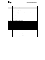
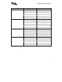
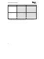
AN430TX Motherboard Specification Update Release Date: September 1998 Order Number: 674301-016 The AN430TX motherboard may contain design defects or errors known as errata which may cause the product to deviate from published specifications. Current characterized errata are documented in this Specification Update. Information in this document is provided in connection with Intel products. No license, express or implied, by estoppel or otherwise, to any intellectual property rights is granted by this document. Except as provided in Intel’s Terms and Conditions of Sale for such products, Intel assumes no liability whatsoever, and Intel disclaims any express or implied warranty, relating to sale and/or use of Intel products including liability or warranties relating to fitness for a particular purpose, merchantability, or infringement of any patent, copyright or other intellectual property right. Intel products are not intended for use in medical, life saving, or life sustaining applications. Intel retains the right to make changes to specifications and product descriptions at any time, without notice. The AN430TX motherboard may contain design defects or errors known as errata which may cause the product to deviate from published specifications. Current characterized errata are available on request. Contact your local Intel sales office or your distributor to obtain the latest specifications before placing your product order. * Third party brands and names are the property of their respective owners. Copies of documents which have an ordering number and are referenced in this document, or other Intel literature, may be obtained from: Intel Corporation P.O. Box 5937 Denver, CO 80217-9808 or call in North America 1-800-548-4725, Europe 44-0-1793-431-155, France 44-0-1793-421-777, Germany 44-0-1793-421-333, other Countries 708-296-9333 Copyright 1998, Intel Corporation CONTENTS REVISION HISTORY ...............................................................................................................................v PREFACE ............................................................................................................................................... vi Specification Update for AN430TX Motherboards GENERAL INFORMATION ......................................................................................................................3 SPECIFICATION CHANGES ...................................................................................................................9 ERRATA.................................................................................................................................................10 SPECIFICATION CLARIFICATIONS......................................................................................................16 DOCUMENTATION CHANGES .............................................................................................................18 This is a blank page AN430TX SPECIFICATION UPDATE REVISION HISTORY Date of Revision Version Description May 1997 -001 This document is the first Specification Update for the Intel® AN430TX motherboard. June 1997 -002 Added Specification Change 1, Specification Clarifications 1-3 and Documentation Changes 1-3. July 1997 -003 Added Erratum 4, Specification Clarification 4 and Documentation Changes 4-9. August 1997 -004 Updated Documentation Changes 1 and 7-8. Added Specification Clarification 5 and Documentation Change 10. September 1997 -005 Updated Documentation Change 10. Added Errata 5 and 6. October 1997 -006 Updated Erratum 3. Added Errata 7-10 and Documentation Change 11. November 1997 -007 Updated Errata 9-10 and Documentation Change 11. Added Erratum 11 and Documentation Changes 12-13. December 1997 -008 Added Erratum 12 and Specification Clarifications 6-7. January 1998 -009 Added Errata 13-14 and Specification Clarification 8. February 1998 -010 Added Erratum 15. April 1998 -011 Added Erratum 16 and Documentation Change 14. May 1998 -012 Added Errata 17-18. Updated Errata 5, 13 and 16. June 1998 -013 Added Documentation Change 15. July 1998 -014 Added Erratum 19 and Documentation Change 16. Updated status of Erratum 16. August 1998 -015 Added Erratum 20. September 1998 -016 Added Erratum 21. Updated status of Erratum 20. v AN430TX SPECIFICATION UPDATE PREFACE This document is an update to the specifications contained in the AN430TX Motherboard Technical Product Specification (Order Number 282955). It is intended for hardware system manufacturers and software developers of applications, operating systems, or tools. It will contain Specification Changes, Errata, Specification Clarifications, and Documentation Changes. Refer to the Pentium Processor Specification Update (Order Number 242480) for specification updates concerning the Pentium processor. Items contained in the Pentium Processor Specification Update that either do not apply to the AN430TX motherboard or have been worked around are noted in this document. Otherwise, it should be assumed that any processor errata for a given stepping are applicable to the Printed Board Assembly (PBA) revision(s) associated with that stepping. Refer to the 82430TX PCIset Specification Update (Order Number 297736) for specification updates concerning the 82430TX PCIset. Items contained in the 82430TX PCIset Specification Update that either do not apply to the AN430TX motherboard or have been worked around are noted in this document. Otherwise, it should be assumed that any PCIset errata for a given stepping are applicable to the Printed Board Assembly (PBA) revision(s) associated with that stepping. Refer to the 82371AB PIIX4 Specification Update (Order Number 297738) for specification updates concerning the 82371AB PIIX4. Items contained in the 82371AB PIIX4 Specification Update that either do not apply to the AN430TX motherboard or have been worked around are noted in this document. Otherwise, it should be assumed that any PCIset errata for a given stepping are applicable to the Printed Board Assembly (PBA) revision(s) associated with that stepping. Nomenclature Specification Changes are modifications to the current published specifications. These changes will be incorporated in the next release of the specifications. Errata are design defects or errors. Characterized errata may cause the AN430TX motherboard’s behavior to deviate from published specifications. Hardware and software designed to be used with any given Printed Board Assembly (PBA) and BIOS revision level must assume that all errata documented for that PBA and BIOS revision are present on all motherboards. Specification Clarifications describe a specification in greater detail or further highlight a specification’s impact to a complex design situation. These clarifications will be incorporated in the next release of the specifications. Documentation Changes include typos, errors, or omissions from the current published specifications. These changes will be incorporated in the next release of the specifications. vi Specification Update for AN430TX Motherboards This is a blank page AN430TX SPECIFICATION UPDATE GENERAL INFORMATION Basic AN430TX Motherboard Identification Information AA Revision PBA Revision 82430TX PCIset Stepping BIOS Revision Notes 672839-304 669379-304 A1 4A3NT0X0.86A.0042.P02 1, 2, 3, 4, 5 672839-305 669379-305 A1 4A3NT0X0.86A.0047.P03 1, 2, 3, 4, 5 672839-306 669379-306 A1 4A3NT0X0.86A.0047.P03 1, 2, 3, 4, 5 672839-307 669379-307 A1 4A3NT0X0.86A.0047.P03 1, 2, 3, 4, 5 672839-308 669379-308 A1 4A3NT0X0.86A.0062.P06 1, 2, 3, 4, 5 672839-309 669379-309 A1 4A3NT0X0.86A.0062.P06 1, 2, 3, 4, 5 680905-302 680904-302 A1 4A3NT0X0.86A.0047.P03 1, 2, 3, 4, 5 680905-303 680904-303 A1 4A3NT0X0.86A.0047.P03 1, 2, 3, 4, 5 680905-304 680904-304 A1 4A3NT0X0.86A.0062.P06 1, 2, 3, 4, 5 680905-305 680904-305 A1 4A3NT0X0.86A.0062.P06 1, 2, 3, 4, 5 NOTES: 1. The AA/PBA number is found on a small label on the component side of the board. 2. The 82430TX PCIset kit used on this PBA revision consists of two different components as follows: Device Stepping S-Spec Numbers 82439TX A1 L238 82371AB B0 L23P 3. 4. 5. The following errata contained in the 82430TX PCIset Specification Update (Order Number 297736) either do not apply to the AN430TX motherboard or have been worked around in this PBA and/or BIOS revision: 1S, 2S. All other errata associated with the PCIset apply to this PBA revision. For specific details of any erratum please refer to the 82430TX PCIset Specification Update. The following errata contained in the 82371AB PIIX4 Specification Update (Order Number 297738) either do not apply to the AN430TX motherboard or have been worked around in this PBA and/or BIOS revision. All other errata associated with the PCIset apply to this PBA revision. For specific details of any erratum please refer to the 82371AB PIIX4-Specification Update . The following errata contained in Part I of the Pentium Processor Specification Update (Order Number 242480) either do not apply to the AN430TX motherboard or have been worked around in this PBA and/or BIOS revision: 5, 7, 9-11, 13-14, 16-17, 29, 31, 34, 36-37, 39, 40, 46, 48-50, 58, 60-64, 66-67, 69, 71, all DP errata, all AP errata, all TCP errata. All other errata in Part I may apply to this revision level of the motherboard, depending on the stepping of the processor or the specific software that is being executed. Also, some of these errata apply only to motherboards being used in an application development environment. For specific details of any erratum please refer to the Pentium Processor Specification Update. 3 AN430TX SPECIFICATION UPDATE Summary Table of Changes The following table indicates the Specification Changes, Errata, Specification Clarifications, or Documentation Changes which apply to the AN430TX motherboard. Intel intends to fix some of the errata in a future revision of the motherboard, and to account for the other outstanding issues through documentation or specification changes as noted. This table uses the following notations: CODES USED IN SUMMARY TABLE Doc: Document change or update that will be implemented. Fix: This erratum is intended to be fixed in a future revision of the motherboard or BIOS. Fixed: This erratum has been previously fixed. NoFix: There are no plans to fix this erratum. Shaded: This erratum is either new or modified from the previous version of the document. NO. PLANS SPECIFICATION CHANGES 1 Doc NO. PLANS 1 NoFix System does not meet FCC Class B with unshielded USB cables 2 NoFix Audio driver does not support Windows* 3.x session within OS/2* Warp* 3 Fixed System BIOS does not recognize bootable USB devices 4 NoFix Video corruption or no video on boot 5 Fixed Memory decrease warning message not displayed 6 Fix Hard drive not detected on boot if user defined 7 Fixed Intel® EtherExpress™ Pro/100B fails to initialize with Windows 95 8 Fixed Potential battery drain if no AC power applied 9 Fixed LS-120 drive does not work as expected in Windows 95 10 Fix Serial mouse activity does not wake system after APM shutdown 11 Fix Stuck or depressed key during POST may cause system hang 12 Fixed Unable to define IDE heads value for secondary IDE hard drive in BIOS Setup 13 Fixed System BIOS may corrupt audio add-in card EEPROM 14 NoFix Windows 95 will not boot if LS-120 drive is only device on IDE channel 15 NoFix Advanced Power Management may suspend system during CD-ROM playback 16 Fixed BIOS does not correctly size 64 MB or larger DIMMs 17 Fixed System will not boot with network as first boot device 18 Fixed Unattended start feature does not require password before boot 19 Fixed System BIOS does not display user logo during POST 4 Support for 233 MHz Pentium processors with MMX technology ERRATA AN430TX SPECIFICATION UPDATE NO. PLANS ERRATA 20 NoFix System using 3-mode floppy drive cannot read XDF format diskettes 21 NoFix System will not boot from ISA video adapter if Scan User Flash is enabled NO. PLANS 1 Doc Advanced Power Management (APM) will not function as expected with Universal Serial Bus (USB) enabled SPECIFICATION CLARIFICATIONS 2 Doc LS-120 drive and floppy will not function as expected for BIOS recovery 3 Doc PCI 2.1 Specification optional features 4 Doc Supervisor and user passwords 5 Doc Power supply considerations 6 Doc LS-120 drive configured as a boot device 7 Doc Resource allocation with all PCI slots used 8 Doc Using shift print screen in BIOS Setup NO. PLANS 1 Doc Revision of Section 1.6.1, “Main Memory” 2 Doc Addition of “Power On” section 3 Doc Revision of Section 5.1, “Specifications” 4 Doc Revision of Section 1.7.1, “82439TX System Controller (MTXC)” 5 Doc Revision of Section 1.12, “Add-In Board Expansion Connectors” 6 Doc Revision of Section 1.13.1, “Processor Configuration (J9C1-C, D)” 7 Doc Revision of Section 1.6.1.1, “EDO DRAM” 8 Doc Revision of Section 1.8.1, “Serial Ports” 9 Doc Revision of Section 1.13.3, “Clear CMOS (J9C1-A)” 10 Doc Revision of Section 1.16.1, “Power Supply Considerations” 11 Doc Revision of Section 3.1.12, “USB Support” 12 Doc Addition of “BIOS Beep Codes” section 13 Doc Revision of Section 3.1.4, “PCI IDE Support” DOCUMENTATION CHANGES 14 Doc Revision of video memory address 15 Doc Change to description of Manufacturing Options 16 Doc Addition of section describing real time clock 5 AN430TX SPECIFICATION UPDATE The errata described in this specification update apply to combinations of PBA revision and BIOS revision as shown in the table below. Descriptions of the individual errata referred to by number in the table below are found in the ERRATA section of this document. PBA Revision BIOS Revision Errata That Apply 669379-304 4A3NT0X0.86A.0042.P02 1-3, 5-15, 17-18, 20-21 4A3NT0X0.86A.0047.P03 1-3, 5-15, 17-18, 20-21 4A3NT0X0.86A.0062.P06 1-2, 5-6, 8, 10-11, 14-15, 17-18, 2021 4A3NT0X0.86A.0082.P07 1-2, 6, 8, 10-11, 14-16, 18-21 4A3NT0X0.86A.0086.P08 1-2, 6, 8, 10-11, 14-16, 19-21 4A3NT0X0.86A.0088.P09 1-2, 6, 8, 10-11, 14-15, 20-21 669379-305 669379-306 669379-307 6 4A3NT0X0.86A.0042.P02‡ 1-3, 5-15, 17-18, 20-21 4A3NT0X0.86A.0047.P03 1-3, 5-15, 17-18, 20-21 4A3NT0X0.86A.0062.P06 1-2, 5-6, 8, 10-11, 14-15, 17-18, 2021 4A3NT0X0.86A.0082.P07 1-2, 6, 8, 10-11, 14-16, 18-21 4A3NT0X0.86A.0086.P08 1-2, 6, 8, 10-11, 14-16, 19-21 4A3NT0X0.86A.0088.P09 1-2, 6, 8, 10-11, 14-15, 20-21 ‡ 1-3, 5-15, 17-18, 20-21 4A3NT0X0.86A.0047.P03 1-3, 5-15, 17-18, 20-21 4A3NT0X0.86A.0062.P06 1-2, 5-6, 8, 10-11, 14-15, 17-18, 2021 4A3NT0X0.86A.0082.P07 1-2, 6, 8, 10-11, 14-16, 18-21 4A3NT0X0.86A.0086.P08 1-2, 6, 8, 10-11, 14-16, 19-21 4A3NT0X0.86A.0088.P09 1-2, 6, 8, 10-11, 14-15, 20-21 4A3NT0X0.86A.0042.P02 ‡ 1-3, 5-15, 17-18, 20-21 4A3NT0X0.86A.0047.P03 1-3, 5-15, 17-18, 20-21 4A3NT0X0.86A.0062.P06 1-2, 5-6, 8, 10-11, 14-15, 17-18, 2021 4A3NT0X0.86A.0082.P07 1-2, 6, 8, 10-11, 14-16, 18-21 4A3NT0X0.86A.0086.P08 1-2, 6, 8, 10-11, 14-16, 19-21 4A3NT0X0.86A.0088.P09 1-2, 6, 8, 10-11, 14-15, 20-21 4A3NT0X0.86A.0042.P02 AN430TX SPECIFICATION UPDATE PBA Revision 669379-308 669379-309 680904-302 680904-303 BIOS Revision Errata That Apply ‡ 1-3, 5-15, 17-18, 20-21 4A3NT0X0.86A.0047.P03‡ 1-3, 5-15, 17-18, 20-21 4A3NT0X0.86A.0062.P06 1-2, 5-6, 8, 10-11, 14-15, 17-18, 2021 4A3NT0X0.86A.0082.P07 1-2, 6, 8, 10-11, 14-16, 18-21 4A3NT0X0.86A.0086.P08 1-2, 6, 8, 10-11, 14-16, 19-21 4A3NT0X0.86A.0088.P09 1-2, 6, 8, 10-11, 14-15, 20-21 4A3NT0X0.86A.0042.P02 ‡ 1-3, 5-15, 17-18, 20-21 4A3NT0X0.86A.0047.P03‡ 1-3, 5-15, 17-18, 20-21 4A3NT0X0.86A.0062.P06 1-2, 5-6, 8, 10-11, 14-15, 17-18, 2021 4A3NT0X0.86A.0082.P07 1-2, 6, 8, 10-11, 14-16, 18-21 4A3NT0X0.86A.0086.P08 1-2, 6, 8, 10-11, 14-16, 19-21 4A3NT0X0.86A.0088.P09 1-2, 6, 8, 10-11, 14-15, 20-21 4A3NT0X0.86A.0042.P02 ‡ 1-7, 9-15, 17-18, 20-21 4A3NT0X0.86A.0047.P03 1-7, 9-15, 17-18, 20-21 4A3NT0X0.86A.0062.P06 1, 2, 4-6, 10-11, 14-15, 17-18, 20-21 4A3NT0X0.86A.0082.P07 1-2, 4, 6, 10-11, 14-16, 18-21 4A3NT0X0.86A.0086.P08 1-2, 4, 6, 10-11, 14-16, 19-21 4A3NT0X0.86A.0088.P09 1-2, 4, 6, 10-11, 14-15, 20-21 4A3NT0X0.86A.0042.P02‡ 1-7, 9-15, 17-18, 20-21 4A3NT0X0.86A.0042.P02 4A3NT0X0.86A.0047.P03 1-7, 9-15, 17-18, 20-21 4A3NT0X0.86A.0062.P06 1, 2, 4-6, 10-11, 14-15, 17-18, 20-21 4A3NT0X0.86A.0082.P07 1-2, 4, 6, 10-11, 14-16, 18-21 4A3NT0X0.86A.0086.P08 1-2, 4, 6, 10-11, 14-16, 19-21 4A3NT0X0.86A.0088.P09 1-2, 4, 6, 10-11, 14-15, 20-21 7 AN430TX SPECIFICATION UPDATE PBA Revision 680904-304 680904-305 BIOS Revision 4A3NT0X0.86A.0042.P02 Errata That Apply ‡ 1-7, 9-15, 17-18, 20-21 4A3NT0X0.86A.0047.P03‡ 1-7, 9-15, 17-18, 20-21 4A3NT0X0.86A.0062.P06 1, 2, 4-6, 10-11, 14-15, 17-18, 20-21 4A3NT0X0.86A.0082.P07 1-2, 4, 6, 10-11, 14-16, 18-21 4A3NT0X0.86A.0086.P08 1-2, 4, 6, 10-11, 14-16, 19-21 4A3NT0X0.86A.0088.P09 1-2, 4, 6, 10-11, 14-15, 20-21 4A3NT0X0.86A.0042.P02‡ 1-7, 9-15, 17-18, 20-21 4A3NT0X0.86A.0047.P03 ‡ 1-7, 9-15, 17-18, 20-21 4A3NT0X0.86A.0062.P06 1, 2, 4-6, 10-11, 14-15, 17-18, 20-21 4A3NT0X0.86A.0082.P07 1-2, 4, 6, 10-11, 14-16, 18-21 4A3NT0X0.86A.0086.P08 1-2, 4, 6, 10-11, 14-16, 19-21 4A3NT0X0.86A.0088.P09 1-2, 4, 6, 10-11, 14-15, 20-21 NOTE: ‡ This combination of BIOS revision and PBA revision has not undergone regression testing. Use of a PBA with downrevision BIOS is an untested combination and is undertaken at the user’s risk. 8 AN430TX SPECIFICATION UPDATE SPECIFICATION CHANGES The Specification Changes listed in this section apply to the AN430TX Motherboard Technical Product Specification (Order Number 282955). All Specification Changes will be incorporated into a future version of that specification. 1. Support for 233 MHz Pentium processors with MMX technology Support for 233 MHz Pentium processors with MMX technology is available in PBA revision 669379-304, 680904-302 and higher. Below are the jumper settings: Processor Freq. (MHz) 100/233 Jumpers J9C1-C 5-6 Jumpers J9C1-D 1-2 and 4-5 Host Bus Freq. (MHz) 66 PCI Bus Freq. (MHz) 33 ISA Bus Freq. (MHz) 8.33 Bus/Processor Freq. Ratio 1.5 NOTE: There are no additional jumpering requirements for Pentium processors with MMX technology. The 100 MHz Pentium processor and the 233 MHz Pentium processor with MMX technology have identical jumper settings. The motherboard automatically detects which processor type is installed. 9 AN430TX SPECIFICATION UPDATE ERRATA 1. System Does Not Meet FCC Class B with Unshielded USB Cables PROBLEM: The motherboard will generate excessive electromagnetic radiation on unshielded USB cables, even if no device or a low speed (sub-channel) USB device is attached to the cable. IMPLICATION: The system will not meet FCC Part 15 Class B requirements when unshielded USB cable is used. This is a violation of the USB v1.0 specification. WORKAROUND: Use USB devices with shielded cable that meet the requirements for high speed (fully-rated) USB devices. STATUS: This erratum will not be fixed. 2. Audio Driver Does Not Support Windows* 3.x Session Within OS/2* Warp* PROBLEM: The AN430TX motherboard audio drivers for OS/2* Warp* or Windows* 3.x do not support audio during a Windows 3.x session within OS/2 Warp. IMPLICATION: No audio is available during a Windows 3.x session within OS/2 Warp. Normal audio support will be available in native OS/2 Warp. WORKAROUND: None. STATUS: This erratum will not be fixed. 3. System BIOS Does Not Recognize Bootable USB Devices PROBLEM: The system BIOS does not recognize a USB keyboard or mouse during a system boot. A USB keyboard or mouse is not recognized until an operating system that supports USB is loaded. IMPLICATION: 1. The user is not able to use a USB keyboard to enter the BIOS Setup or to respond to error messages that are displayed before an operating system with USB support is loaded. 2. The user is not able to use a USB keyboard or mouse with any operating system that does not have USB support. WORKAROUND: Use a standard PS/2* style keyboard and mouse in any configuration where input is required before an operating system with USB support is loaded. STATUS: This erratum was fixed in BIOS revision 4A3NT0X0.86A.0062.P06. 4. Video Corruption or No Video on Boot PROBLEM: An ATI* 264GTU device initialization problem will occur on power up when the power supply ramping of the 3.3 V leads the 5.0 V by 5 ms or more. The 2.01 ATX Specification recommends that the 3.3 V DC rails always be held at a lower potential than the 5 V DC rails during power-up and power-down transition. IMPLICATION: The onboard video device will not initialize causing the system to display video corruption or no video on boot. 10 AN430TX SPECIFICATION UPDATE WORKAROUND: Use a power supply that meets the recommendation in the 2.01 ATX Specification. STATUS: This erratum will not be fixed. 5. Memory Decrease Warning Message Not Displayed PROBLEM: During POST, the BIOS will not generate and display a memory decrease warning message on the screen. IMPLICATION: The user will not be warned about a decrease in the amount of memory. WORKAROUND: None. STATUS: This erratum was fixed in BIOS revision 4A3NT0X0.86A.0082.P07. 6. Hard Drive Not Detected on Boot if User Defined PROBLEM: If the drive type in BIOS Setup is set to USER, the hard drive will not be detected by the motherboard at boot. IMPLICATION: The hard drive will not be detected by the BIOS during the boot process and will not be available to the operating system. WORKAROUND: None. STATUS: This erratum will be fixed in a future BIOS revision. 7. Intel® EtherExpress™ Pro/100B Fails to Initialize With Windows* 95 PROBLEM: The system BIOS allocates 48 KB of memory at location C000H:0 rather than 44 KB as expected. IMPLICATION: Since the EtherExpress™ Pro/100B attempts to map memory starting at location CB00H:0 by default, this results in a resource conflict with the system BIOS. Therefore, Windows* 95 will be unable to initialize the EtherExpress Pro/100B and an exclamation mark will be displayed in Device Manager for this device. WORKAROUND: Manually move the EtherExpress Pro/100B memory range to D000 or higher in Windows 95 Device Manager. STATUS: This erratum was fixed in BIOS revision 4A3NT0X0.86A.0062.P06. 8. Potential Battery Drain if No AC Power Applied PROBLEM: A potential battery drain condition caused by the AC power loss recovery circuit can cause the battery to source approximately 500 µA current instead of the typical 3 µA drawn when the system is powered off. This drain condition can occur if AC power is removed from the power supply and the front panel on/off switch is depressed. IMPLICATION: The excessive battery drain state can result in a shortened battery life. The battery will drain completely over a period of 3 to 4 weeks if left in this state. Reapplying AC power eliminates the excessive battery drain condition. A battery that has been completely drained will cause a CMOS checksum error to be displayed the next time that the system is powered on. 11 AN430TX SPECIFICATION UPDATE WORKAROUND: None. STATUS: This erratum was fixed in PBA revision 669379-306. 9. LS-120 Drive Does Not Work as Expected in Windows* 95 PROBLEM: After restarting Windows* 95 from MS-DOS* mode, the system BIOS does not configure the diskette parameter table correctly if an LS-120 drive is the only floppy drive in the system. IMPLICATION: Windows 95 will report the LS-120 drive as a hard drive instead of a floppy drive and will report a floppy drive available as Drive A. If drive A is subsequently accessed, the system will lock up. The problem does not occur if a 1.44 MB 3-1/2” floppy drive is also present as either drive A or drive B. WORKAROUND: None. STATUS: This erratum was fixed in BIOS revision 4A3NT0X0.86A.0062.P06. 10. Serial Mouse Activity Does Not Wake System After APM Shutdown PROBLEM: The system BIOS does not recognize activity from a serial mouse as an APM event. IMPLICATION: The system will not be restored from a power-managed state until keyboard activity occurs. WORKAROUND: The system BIOS does recognize activity from a PS/2* style mouse. STATUS: This erratum will be fixed in a future BIOS revision. 11. Stuck or Depressed Key During POST May Cause System Hang PROBLEM: The BIOS is unable to detect when a key on the keyboard is stuck or depressed during Power On Self Test (POST). IMPLICATION: If a key is stuck or depressed during POST, the system BIOS will continue to read data from the keyboard, resulting in a system hang condition. WORKAROUND: None. STATUS: This erratum will be fixed in a future BIOS revision. 12. Unable to Define IDE Heads Value for Secondary IDE Hard Drive in BIOS Setup PROBLEM: The Secondary IDE Master/Slave Configuration Submenu in BIOS Setup does not display a field for the number of hard disk drive heads and has no value assigned for it in manual configuration mode. IMPLICATION: Since BIOS setup does not allow the user to define the number of hard disk heads, thus the system BIOS cannot detect the secondary IDE hard drive. WORKAROUND: None. STATUS: This erratum was fixed in BIOS revision 4A3NT0X0.86A.0062.P06. 12 AN430TX SPECIFICATION UPDATE 13. System BIOS May Corrupt Audio Add-In Card EEPROM PROBLEM: Audio add-in cards using the Yamaha OPL3-SA2 or OPL3-SA3 audio codec have the same hardware identification number that is used by the Yamaha audio device integrated on the motherboard. This causes the system BIOS to inadvertently write information into the audio add-in card’s serial EEPROM during system startup, thereby corrupting the audio add-in card’s EEPROM contents. IMPLICATION: The audio add-in card will not operate and no audio will be available. WORKAROUND: Disable the onboard audio in BIOS Setup before installing an audio add-in card. STATUS: This erratum was fixed in BIOS revision 4A3NT0X0.86A.0062.P06. 14. Windows* 95 Will Not Boot if LS-120 Drive is Only Device on IDE Channel PROBLEM: An LS-120 drive will not be recognized by Windows* 95 if it is the only device on the IDE channel. IMPLICATION: If an LS-120 drive is the only device on an IDE channel, a black screen with a cursor blinking in the upper left hand corner will be displayed when Windows 95 is starting to boot and the system will hang. WORKAROUND: The LS-120 drive is recognized when connected as either the master or the slave on an IDE channel with another device. STATUS: This erratum will not be fixed. 15. Advanced Power Management May Suspend System During CDROM Playback PROBLEM: ATAPI devices (such as CD-ROM and DVD drives) do not reset the inactivity timer that is used by Advanced Power Management to determine when to place the system into suspend mode. IMPLICATION: When playback of an audio CD or a DVD file is the only system activity, the system will go into suspend mode when the inactivity timer expires. WORKAROUND: Temporarily disable the Low-power standby and Shut off monitor options on the Display Properties, Screen Saver menu. This menu is available from the Windows 95 Control Panel. STATUS: This erratum will not be fixed. 16. BIOS Does Not Correctly Size 64 MB or Larger DIMMs PROBLEM: Because of an incorrect register setting in the memory controller, the BIOS may not correctly identify the size of 64 MB or larger DIMMs. IMPLICATION: Only 16 MB of the memory will be reported by the power on self-test (POST). The additional memory will not be available to the operating system. This erratum applies only to BIOS revision 4A3NT0X0.86A.0082.P07 and later. WORKAROUND: None. STATUS: This erratum was fixed in BIOS revision 4A3NT0X0.86A.0088.P09. 13 AN430TX SPECIFICATION UPDATE 17. System Will Not Boot with Network as First Boot Device PROBLEM: The feature allowing the system to boot from the network is not implemented. After the attempt to boot from a network device selected as the first boot device fails, the system BIOS does not attempt to boot from any additional boot devices specified in the BIOS Setup program. IMPLICATION: If Network boot is selected as the first boot device, the system will hang. WORKAROUND: Remove Network boot from the boot sequence. STATUS: This erratum was fixed in BIOS revision 4A3NT0X0.86A.0082.P07. 18. Unattended Start Feature Does Not Require Password Before Boot PROBLEM: The Unattended Start feature at power on allows the system to boot without any password being entered at the keyboard, even though a user or administrator password has been set in the BIOS Setup program. IMPLICATION: A system that is booted without an operator in attendance could be vulnerable to unauthorized access. WORKAROUND: None. STATUS: This erratum was fixed in BIOS revision 4A3NT0X0.86A.0086.P08. 19. System BIOS Does Not Display User Logo During POST PROBLEM: The status bit that allows display of a user logo during the POST process is disabled in some versions of the BIOS. IMPLICATIONS: If a user logo has been defined and loaded in the user logo flash memory area, it will not be displayed. This erratum only affects BIOS versions 4A3NT0X0.86A.0082.P07 and later. WORKAROUND: None. STATUS: This erratum was fixed in BIOS revision 4A3NT0X0.86A.0088.P09. 20. System Using 3-Mode Floppy Drive Cannot Read XDF Format Diskettes PROBLEM: The buffer area that stores floppy drive parameters does not have room to store the speed information to allow a 3-mode floppy drive to read a diskette in the XDF format. IMPLICATION: A system that has a 3-mode floppy drive cannot be used to install a program or operating system, such as PC-DOS 7.0, that is distributed on XDF format diskettes. WORKAROUND: None. STATUS: This erratum will not be fixed. 14 AN430TX SPECIFICATION UPDATE 21 System Will Not Boot From ISA Video Adapter if Scan User Flash is Enabled PROBLEM: If the option to scan the user flash area during the boot process is enabled in the BIOS setup program, the system will hang when the BIOS attempts to initialize an ISA video adapter. This erratum does not affect PCI video adapters. IMPLICATION: A user who requires an ISA video adapter will not be able to use the scan user flash area option. WORKAROUND: None. STATUS: This erratum will not be fixed. 15 AN430TX SPECIFICATION UPDATE SPECIFICATION CLARIFICATIONS The Specification Clarifications listed in this section apply to the AN430TX Motherboard Technical Product Specification (Order Number 282955). All Specification Clarifications will be incorporated into a future version of that specification. 1. Advanced Power Management (APM) Will Not Function as Expected with Universal Serial Bus (USB) Enabled The following will be added to Section 1.7.3, Universal Serial Bus and Section 3.1.8, Advanced Power Management: Advanced Power Management will not function as expected when a USB keyboard or mouse is used. USB activity is not monitored by the APM event counter, therefore, activity from a USB keyboard or mouse will not keep the system awake or bring a system out of APM sleep mode. If a USB keyboard or mouse is being used, APM should be disabled. 2. LS-120 Drive and Floppy Will Not Function as Expected for BIOS Recovery The following note will be added to Section 3.1.14, Recovering BIOS Data: The LS-120 drive does not work as a legacy floppy drive when attempting to perform a BIOS recovery. A 1.44 MB disk must be used in place of an LS-120 disk in the LS-120 drive for BIOS recovery. 3. PCI 2.1 Specification Optional Features The following will be added to Section 1.12, Add-in Board Expansion Connectors: The following optional features in the PCI 2.1 Specification are not implemented on the AN430TX motherboard: • Cache Support Pins SBO# and SDONE (Section 2.2.7) • PRSNTx# (Section 2.2.8) • CLKRUN# (Section 2.2.8) • 64 Bit Bus Extension Pins (Section 2.2.9) • 66 MHz support (Section 2.2.8) • JTAG/Boundary scan (Section 2.2.10) 4. Supervisor and User Passwords The following will be added to Section 3.2.5, Security Menu: If a supervisor password has been set, but no user password has been set, a user can create a password by entering BIOS Setup at boot by pressing the F2 key and pressing enter at the supervisor password prompt. Once in Setup, a user will be able to create a new user password. 16 AN430TX SPECIFICATION UPDATE Once defined, a user password can be cleared by either defining a new user password in BIOS Setup, or by moving the Password Clear jumper (J9C1-A) on the motherboard. See Section 1.13.2, Password Clear for more information on how to use this jumper. 5. Power Supply Considerations The AN430TX motherboard has been designed to be configured in a system that uses a power supply that complies with the recommendations of ATX Specification Version 2.01. See Documentation Change 10 for the specific recommendations that must be met by a power supply for the motherboard. 6. LS-120 Drive Configured as a Boot Device The second paragraph in Section 1.7.4.1, LS-120 Support will be replaced in its entirety as follows: The motherboard allows connection of an LS-120 compatible drive and a standard 3.5-inch diskette drive. The LS-120 drive can be configured as a boot device, if selected as a floppy device in the BIOS setup utility. 7. Resource Allocation With All PCI Slots Used The BIOS assigns resources to PCI boot devices (video cards and SCSI controllers, for example) during POST when Plug and Play is enabled in BIOS Setup. PCI and ISA non-boot devices (network cards and audio, for example) will not have resources assigned by the BIOS during POST. A Plug and Play operating system assigns resources to PCI and ISA non-boot devices when it loads. 8. Using Shift Print Screen in BIOS Setup In order to use the Shift Print Screen function to print screens from BIOS Setup, PnP OS must be set to no. If PnP OS is set to yes in BIOS Setup, the Shift Print Screen function will not work. The BIOS does not assign resources to the parallel port when PnP OS is set to yes in BIOS Setup. Resources for the parallel port will be allocated by the plug and play operating system when it loads. If PnP OS is set to no, the BIOS allocates resources to the parallel port. 17 AN430TX SPECIFICATION UPDATE DOCUMENTATION CHANGES The Documentation Changes listed in this section apply to the AN430TX Motherboard Technical Product Specification (Order Number 282955). All Documentation Changes will be incorporated into a future version of the appropriate AN430TX motherboard documentation. 1. Revision of Section 1.6.1, Main Memory This section will be replaced in its entirety as follows: The motherboard has two 168-pin DIMM sockets. Memory can be installed in one or two sockets. Minimum memory size is 8 MB. Maximum memory size is 128 MB for EDO memory and 256 MB SDRAM memory. The BIOS automatically detects memory type, size, and speed so no jumper settings are required. The motherboard supports the following: • 168-pin 3.3 V DIMMs with gold-plated contacts • 60 and 66 MHz bus speeds • 60 ns 3.3 V EDO DRAM • Unrestricted CAS Latency 2 unbuffered 4-clock 3.3 V SDRAM • Caching for the first 64 MB of main memory • 64-bit data path • Single- or double-sided DIMMs in the following sizes: DIMM Size Type Configuration Technology 8 MB 60 ns EDO 1M x 64 16 Mbit 16 MB 60 ns EDO 2M x 64 16 Mbit 32 MB 60 ns EDO 4M x 64 16 Mbit 64 MB 60 ns EDO 8M x 64 16 Mbit 8 MB CAS Latency 2 SDRAM 1M x 64 16 Mbit 16 MB CAS Latency 2 SDRAM 2M x 64 16 Mbit 32 MB CAS Latency 2 SDRAM 4M x 64 16 Mbit 64 MB CAS Latency 2 SDRAM 8M x 64 64 Mbit 128 MB CAS Latency 2 SDRAM 16M x 64 64 Mbit Memory type, size, and speed can vary between sockets, so EDO and SDRAM can be installed on the same motherboard. 168-pin parity DIMMs can be installed but are not recommended for the following reasons: • The motherboard does not provide parity checking or ECC • Parity DIMMs cause excessive capacitive loading on memory data and address lines 18 AN430TX SPECIFICATION UPDATE 2. Addition of Power On Section The following will be added to Section 1.11.2, Front Panel Connectors: POWER ON This header must be connected to a front panel power switch. The switch must pull the SW_ON# pin to ground for at least 50 ms to signal the power supply to switch on or off. (The time requirement is due to the motherboard’s internal debounce circuitry.) At least two seconds must pass before the motherboard will recognize another on/off signal. The system will turn on for 300 ms when AC power is first applied to the board. CAUTION If you need to turn off the computer during POST or because of a system lock-up, hold the power switch in for four seconds; otherwise the computer will not switch off. 3. Revision of Section 5.1, Specifications The following note will be added to the table entry for PCI compliance: NOTE: Certain optional PCI features have not been implemented on this motherboard, see section 1.14 for more information. 4. Revision of Section 1.7.1, 82439TX System Controller (MTXC) The fourth bullet in this section will be replaced in its entirety as follows: • Fully synchronous minimum latency PCI bus interface 5. PCI compliance (see Section 5.1 for compliance level) 30 and 33 MHz bus speeds PCI to DRAM data transfers up to or greater than 100 MB/sec Up to four PCI masters in addition to the PIIX4 Revision of Section 1.12, Add-In Board Expansion Connectors The text in the first paragraph of this section will be replaced in its entirety as follows: The motherboard Expansion Slots support up to four bus mastering PCI and up to three ISA add-in boards. One of the PCI slots may be shared with an ISA slot. 6. Revision of Section 1.13.1, Processor Configuration (J9C1-C, D) The following note will be added to the bottom of Table 30 in this section: NOTE: Pins 1, 2 and 3 on Jumper J9C1-C are not used. 19 AN430TX SPECIFICATION UPDATE 7. Revision of Section 1.6.1.1, EDO DRAM The following will be added to the end of this section: EDO DIMM should meet the Intel 60 ns 64-bit 3.3 V unbuffered EDO DIMM v1.2 specification. CAUTION Due to loading anomalies, using EDO DIMMs with a n x 4 DRAM base in the AN430TX motherboard is not recommended. For example, a DIMM that uses sixteen 16 Mbit x 4 devices should not be used. 8. Revision of Section 1.8.1, Serial Ports This section will be replaced in its entirety as follows: The motherboard has one 9-pin D-Sub serial port connector located on the back panel, and one keyed 10-pin header located on the motherboard for cabling to the back panel. The 16540 and 16550A compatible UARTs allow data transfers at speeds up to 115.2 Kbaud with BIOS serial port support. 9. Revision of Section 1.13.3, Clear CMOS (J9C1-A) This section will be replaced in its entirety as follows: Allows CMOS settings to be reset to default values by moving the jumper from pins 4-5 to pins 5-6 and turning the system on. When the system reports that “NVRAM cleared by jumper”, the system can be turned off, and the jumper should be returned to the 4-5 position to restore normal operation. Default is for this jumper to be on pins 4-5. Caution: This procedure should only be done if, after a BIOS update, the system does not boot to a point where Setup can be entered or if, after CMOS default settings have been restored from within the Setup program, the system does not boot to the operating system. 10. Revision of Section 1.16.1, Power Supply Considerations This section will be replaced in its entirety as follows: For typical configurations, the motherboard is designed to operate with at least a 200 W power supply (see Section 5.1 for the specification). A higher-wattage power supply should be used for heavily-loaded configurations. The power supply must comply with the following recommendations found in the indicated sections of that specification: 20 • The potential relation between 3.3VDC and +5VDC power rails (Section 4.2) • All timing parameters (Section 4.2.1.3) • All voltage tolerances (Section 4.2.2) AN430TX SPECIFICATION UPDATE 11. Revision of Section 3.1.12, USB Support This section will be replaced in its entirety as follows: USB LEGACY SUPPORT USB legacy support enables USB keyboards and mice to be used even when no operating system USB drivers are in place. By default, USB legacy support is disabled. USB legacy support is only intended to be used in accessing BIOS Setup and installing an operating system that supports USB. This sequence describes how USB legacy support operates in the default (disabled) mode. 1. When you power up the computer, USB legacy support is disabled. 2. POST begins. 3. USB legacy support is temporarily enabled by the BIOS. This allows you to use a USB keyboard to enter the Setup program or the maintenance mode. 4. POST completes and disables USB legacy support (unless it was set to Enabled while in Setup). 5. The operating system loads. While the operating system is loading, USB keyboards and mice are not recognized. After the operating system loads the USB drivers, the USB devices are recognized. To install an operating system that supports USB, enable USB Legacy support in BIOS Setup and follow the operating system’s installation instructions. Once the operating system is installed and the USB drivers configured, USB legacy support is no longer used. USB Legacy Support can be left enabled in BIOS Setup if needed. Notes on using USB legacy support: • If USB legacy support is enabled, don't mix USB and PS/2* keyboards and mice. For example, do not use a PS/2 keyboard with a USB mouse, or a USB keyboard and a PS/2 mouse. • Do not use USB devices with an operating system that does not support USB. USB legacy is not intended to support the use of USB devices in a non USB operating system. • USB legacy support is for keyboards and mice only. Hubs and other USB devices are not supported. 12. Addition of BIOS Beep Codes Section The following will be added after Section 4.2. Remaining tables will be renumbered accordingly. BIOS BEEP CODES Whenever a recoverable error occurs during Power-On Self Test (POST), the BIOS displays an error message describing the problem. The BIOS also issues a beep code (one long tone followed by two short tones) during POST if the video configuration fails (no card installed or faulty) or if an external ROM module does not properly checksum to zero. An external ROM module (e.g video BIOS) can also issue audible errors, usually consisting of one long tone followed by a series of short tones. For more information on the beep codes issued, check the documentation for that external device. 21 AN430TX SPECIFICATION UPDATE There are several POST routines that issue a POST Terminal Error and shut down the system if they fail. Before shutting down the system, the terminal-error handler issues a beep code signifying the test point error, writes the error to I/O port 80h, attempts to initialize the video and writes the error in the upper left corner of the screen (using both mono and color adapters). If POST completes normally, the BIOS issues one short beep before passing control to the operating system. Table 43. Beeps BIOS Beep Codes Port 80h Code Explanation 1-2-2-3 16h BIOS ROM checksum 1-3-1-1 20h Test DRAM refresh 1-3-1-3 22h Test 8742 Keyboard Controller 1-3-3-1 28h Autosize DRAM 1-3-3-2 29h Initialize POST Memory Manager 1-3-3-3 2Ah Clear 512 KB base RAM 1-3-4-1 2Ch RAM failure on address line xxxx 1-3-4-3 2Eh RAM failure on data bits xxxx of low byte of memory bus 1-4-1-1 30h RAM failure on data bits xxxx of high byte of memory bus 2-1-2-2 45h POST device initialization 2-1-2-3 46h Check ROM copy right notice 2-2-3-1 58h Test for unexpected interrupts 2-2-4-1 5Ch Test RAM between 512 and 640 KB 1-2 98h Search for option ROMs. One long, two short beeps on checksum failure 13. Revision of Section 3.1.4, PCI IDE Support This section will be replaced in its entirety as follows: If you select “Auto” in Setup, the BIOS automatically sets up the two local bus IDE connectors with independent I/O channel support. The IDE interface supports hard drives up to PIO Mode 4 and recognizes any ATAPI devices, including CD-ROM drives, tape drives and Ultra DMA drives (see Section 5.1 for the supported version of ATAPI). Add-in ISA IDE controllers are not supported. The BIOS determines the capabilities of each drive and configures them to optimize capacity and performance. To take advantage of the high capacities typically available today, hard drives are automatically configured for Logical Block Addressing (LBA) and to PIO Mode 3 or 4, depending on the capability of the drive. You can override the auto-configuration options by specifying manual configuration in Setup. The ATAPI Specification recommends that ATAPI devices be configured as shown in Table 41. 22 AN430TX SPECIFICATION UPDATE 14. Revision of Video Memory Address In Table 34, Memory Map, the address ranges for Video memory and BIOS will be changed to 640K-812K (decimal) and A0000-CAFFF (hex). This will also change the ranges for Available High DOS memory to 812K-896K (decimal) and CB000-DFFFF (hex). The following note will be added applicable to Video Memory and BIOS: Note: Applies only to boards with onboard video. Video memory usage for other boards is determined by the add-in video card. 15. Change to Description of Manufacturing Options The following will be added as the first paragraph of Section 1.2, Motherboard Manufacturing Options: The following are manufacturing options. Not all manufacturing options are available in all marketing channels. Please contact your Intel representative to determine what manufacturing options are available to you. 16. Addition of Section Describing Real Time Clock The following will be added as Section 1.8.5. Following sections will be renumbered as necessary: 1.8.5 Real-Time Clock, CMOS SRAM, and Battery The real-time clock is compatible with DS1287 and MC146818 components. The clock provides a time-ofday clock and a multicentury calendar with alarm features and century rollover. The real-time clock supports 256 bytes of battery-backed CMOS SRAM in two banks that are reserved for BIOS use. The time, date, and CMOS values can be specified in the Setup program. The CMOS values can be returned to their defaults by using the Setup program. An external coin-cell battery powers the real-time clock and CMOS memory. When the computer is not plugged into a wall socket, the battery has an estimated life of three years. When the computer is plugged in, the 3.3 V standby current from the power supply extends the life of the battery. The clock is accurate to ± 13 minutes/year at 25 ºC with 3.3 V applied. 23 This is a blank page This is a blank page This is a blank page