1
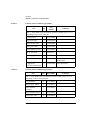
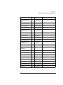
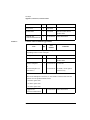
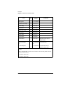
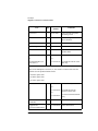
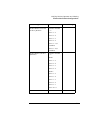
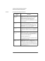
128/238-Slot, 5.2 Gbyte-Drive
Optical Jukebox
Upgrade and Conversion Instructions
Edition 1
Part No. C1104-90018
Printed in USA 3/98
Printing History
New editions of these instructions incorporate all material updated since the
previous edition. The printing date and part number indicate the current edition. The
printing date changes when a new edition is printed. (Minor corrections and updates
incorporated at reprint do not change this date.)
Part number C1104-90018
ii
Edition 1
March 1998
Typographical Conventions
The following typographical conventions are used in these instructions:
Emphasis: Denotes important information.
Keycap:
Keys on the library.
Computer Output: Information displayed in the display window and screen
menu items that you can select.
WARNING
Warnings call attention to a procedure or practice that could result in personal
injury if not correctly performed. Do not proceed until you fully understand
and meet the required conditions.
CAUTION
Cautions call attention to an operating procedure or practice that could damage the
product if not correctly performed. Do not proceed until understanding and meeting
these required conditions.
NOTE
Notes provide information that can be helpful in understanding the operation of the
product.
iii
These Instructions
These upgrade/conversion instructions include the following topics:
Chapter 1
Checking the parts in your kit against the parts list. Checking
that you have the correct tools. Checking that you have the most
current firmware for the jukebox controller and the drives.
Chapter 2
Procedures for adding drives to the jukebox.
Chapter 3
Procedures for converting models of this jukebox from using
2.6 Gbyte drives to using 5.2 Gbyte drives.
Chapter 4
Checking and upgrading the jukebox controller and drives
firmware to the most current revision level.
Chapter 5
Verifying proper jukebox operation, applying labels and
nameplates reflecting the upgrade/conversion, and cleanup.
iv
1
First Steps
1-1
First Steps
Overview
Overview
This chapter provides the following:
•
Contents of each upgrade and conversion kit
•
A checklist of equipment, tools, and firmware needed
1-2
First Steps
Upgrades, Conversions, and Kit Contents
Upgrades, Conversions, and Kit Contents
These instructions explain how to install upgrade/conversion kits for the following:
NOTE
•
Adding two drives to upgrade a four-drive jukebox to a six-drive jukebox.
•
Adding four drives to upgrade a six-drive jukebox to a ten-drive jukebox.
•
Activating and additional 110 slots to upgrade a 128-slot jukebox to a 238-slot
jukebox.
•
Converting 2.6 Gb, four- or six-drive, 128-slot jukeboxes to 5.2 Gb, four- or
six-drive, 128-slot jukeboxes.
•
Converting 2.6 Gb, 6-, 8-, 10-, or 12-drive, 238-slot jukeboxes to 5.2 Gb 4-, 6-,
or 10-drive, 238-slot jukeboxes.
A “J,” “K,” and “L,” suffix on a kit number denotes the sales channel in which it is
distributed.
What is an Upgrade?
Upgrades add drives or available slots to the jukebox.
The 5.2-Gb-drive-based jukebox is.shipped with a all slots installed. The slot
upgrade is done on a “half” jukebox and makes an additional 110 of these
pre-installed slots available for use. Total slots available becomes 238.
For an upgrade, use the following steps:
Step 1 - Check the upgrade kit contents and that you have the necessary equipment,
tools, and firmware.
Step 2 - Go to Chapter 2, “Upgrading Drives and Capacity in 5.2 Gb Drive
Jukeboxes”
Step 3 - Go to Chapter 4, “Checking/Downloading Firmware”
Step 4 - Go to Chapter 5 - “Verifying Proper Jukebox Operation and Labeling.”
1-3
First Steps
Upgrades, Conversions, and Kit Contents
Table 1-1
Contents of the C1154J/K/L Upgrade Kits
Part
Qty
Part
Number
Comments
The “x” in the 60000-series part numbers represents a number from “0” to “9”
depending on the revision of the part.
Table 1-2
5.2 Gbyte drive
2
C1113-60x08
drive SCSI cable
1
C1107-60x46
drive interface cable
1
C1107-60x63
drive power cable
1
C1107-60x55
drive enclosure air seal
1
C1107-80604
M3x6 T-10 screw
12
0515-2382
cable clamp
2
1400-0611
product label
1
5181-9902
placed over the current
product label
Upgrade and
Conversion Instructions
1
C1104-90018
These instructions.
Contents of the C1158J/K/L Upgrade Kits
Part
Qty
Part Number
Comments
The “x” in the 60000-series part numbers represents a number from “0” to “9”
depending on the revision of the part.
5.2 Gbyte drive
4
C1113-60x08
power supply, 200 W
1
C1107-60x32
drive enclosure
assembly
3
C1107-60x47
drive enclosure air seal
2
C1107-80604
drive power cable
2
C1107-60x55
1-4
First Steps
Upgrades, Conversions, and Kit Contents
Part
Qty
Part Number
lower drive power
cable
1
C1107-60x68
drive interface cable
2
C1107-60x63
drive SCSI cable
2
C1107-60x46
lower interposer PCA
1
C1110-60x05
lower interposer SCSI
cable
1
C1107-60x60
SCSI interface PCA
1
C1150-60x08
ferrite RFI clamp
1
9170-1648
SCSI module port label
1
C1192-84304
drive/slot map label
1
C1110-84300
single-ended SCSI
terminator
1
1250-2548
SCSI port dust cover
1
1252-5089
wide differential
terminator
1
A1658-62024
68-pin port dust cover
1
1252-7123
M3x6 T-10 screw
24
0515-2382
T-20 screw
18
0515-2282
2-56 screwlock
8
1252-7212
jumper
1
1258-0209
cable clamp
4
1400-0611
short 12 V AC cable
1
C1107-60x50
standoffs
6
0380-4416
Comments
1-5
First Steps
Upgrades, Conversions, and Kit Contents
Part
Table 1-3
Qty
Part Number
Comments
T-15 screw
6
2360-0552
product label
1
5181-9902
placed over the current
product label
Upgrade and
Conversion Instructions
1
C1104-90018
These instructions.
Contents of the C1159J/K/L Upgrade Kits
Part
Qty
Part
Number
Comments
The “x” in the 60000-series part numbers represents a number from “0” to “9”
depending on the revision of the part.
configuration module
1
C1110-60x03
product label
1
5181-9902
placed over the current
product label
1200ex nameplate
1
C1107-84310
C1159J kit
C1107-84312
C1159K, C1159L option
#726 kits only
or
10/238 nameplate (see
Note below)
NOTE:
The 10/238 nameplate is used on 4-,6-, and 10-drive versions of the 238-slot
jukebox. See the product numbers below.
C1107K/L option #726
C1110K/L option #726
C1111K/L option #726
Upgrade and
Conversion Instructions
1-6
1
C1104-90018
These instructions.
First Steps
Upgrades, Conversions, and Kit Contents
What is a Conversion?
Conversions of this jukebox mean changing from a previous capacity drive
technology (2.6 Gbyte) to the new capacity (5.2 Gbyte).
The drives are changed one-to-one. If the jukebox had four 2.6 Gb drives before, it
will have four 5.2 Gb drives after the conversion.
All jukeboxes based on 5.2-Gbyte drives are shipped with all possible cartridge slots
installed. When converting a older jukebox, based on 2.6 Gb drives, slot magazines
are included in the kit so that the converted jukebox will match the configuration of
the jukeboxes as currently shipped — all slots installed.
Future upgrading of the converted jukebox from a “half” to a “full” capacity only
requires plugging in the configuration module — the same as current, 5.2 Gb
jukeboxes.
Check your conversion kit contents in the following table before you begin.
You will be using the following chapters:
Table 1-4
•
Chapter 3 - “Converting From 2.6 Gb Disk Drives to 5.2 Gb Disk Drives”
•
Chapter 4 - “Checking/Downloading Firmware”
•
Chapter 5 - ““Verifying Jukebox Operation, Labeling, and Cleanup”
Contents of the C5138J/K/L Conversion Kits
Part
Qty
Part
Number
Comments
The “x” in the 60000-series part numbers represents a number from “0” to “9”
depending on the revision of the part.
5.2 Gbyte drive
4
C1113-60x08
upper interposer PCA
1
C1110-60x04
interface PCA
1
C1150-60x08
8-slot magazine
24
C1100-44400
6-slot magazine
6
C1160-41215
drive/slot map label
1
C1107-84311
ferrite RFI clamp
2
9170-1735
1-7
First Steps
Upgrades, Conversions, and Kit Contents
Qty
Part
Number
EMI gasket
3
C1160-80602
flat RFI cable clamp
6
1400-0514
cable clamp
2
1400-1742
T-20 screw
6
0515-2282
M3x6 T-10 screw
24
0515-2382
T-15 screw
6
2360-0552
cable clamp
4
1400-0611
wheel chock
1
4320-0448
product label
1
5181-9902
placed over the current
product label
660ex nameplate
1
C1104-84302
C5138J kit only
Part
or
or
6/128 nameplate
C1104-84304
Comments
C5138K and C5138L
option #726 kits only
NOTE:
The 6/128 nameplate is used on 4- and 6-drive of the 128-slot jukebox. See the
product numbers below.
C1104K/L option #726
C1105K/L option #726
1-8
First Steps
Upgrades, Conversions, and Kit Contents
Part
User Guide
Qty
Part
Number
1
C1104-90015
Comments
C5138J kit only
or
C1104-90016
or
Table 1-5
C5138K and C5138L #726
kits only
C1104-90017
C5138L #700 and #768 kits
only
User Guide, localized
CD ROM
1
C1112-90000
C5138J kit only
Upgrade and
Conversion Instructions
1
C1104-90018
These instructions.
Contents of the C5139J/K/L Conversion Kits
Part
Qty
Part
Number
Comments
The “x” in the 60000-series part numbers represents a number from “0” to “9”
depending on the revision of the part.
5.2 Gbyte drive
4
C1113-60x08
upper interposer PCA
1
C1110-60x04
interface PCA
1
C1150-60x08
configuration module
1
C1110-60x03
drive/slot map label
1
C1107-84311
ferrite RFI clamp
2
9170-1735
EMI gasket
3
C1160-80602
flat RFI cable clamp
6
1400-0514
ferrite clamp
2
9170-1648
cable clamp
2
1400-1742
on SCSI cable below lower
interposer PCA
1-9
First Steps
Upgrades, Conversions, and Kit Contents
Part
Part
Number
Qty
Comments
T-20 screw
6
0515-2282
extra assembly and panel
mounting screws
M3x6 T-10 screw
20
0515-2382
for mounting drives in the
drive enclosure
wheel chock
1
4320-0448
cable clamp
6
1400-0611
product label
1
5181-9902
placed over the current
product label
1200 ex nameplate
1
C1107-84310
C5139J
or
or
10/238 nameplate (see
Note below)
C1107-84312
C5139K and C5139L #726
kits only
NOTE:
The 10/238 nameplate is used on 4-,6-, and 10-drive versions of the 238-slot
jukebox. See the product numbers below.
C1107K/L option #726
C1110K/L option #726
C1111K/L option #726
User Guide
1
C1104-90015
C1139J kit only
or
C1104-90016
or
C5139K and C5139L
option #726 kits only
C1104-90017
C5139L #700 and #768 kits
only
User Guide, localized
CD ROM
1
C1112-90000
C5133J kit only
Upgrade and
Conversion Instructions
1
C1104-90018
These instructions.
1-10
First Steps
Equipment, Tools, and Firmware Needed
Equipment, Tools, and Firmware Needed
PC Tool Equipment and Software Needed
When upgrading or converting the library you will be connecting your PC tool to the
jukebox for two reasons: downloading firmware to the jukebox controller and drives
and verifying proper operation of the drives after installation. The following
hardware and software is required:
•
IBM AT-compatible computer
•
Adaptec interface board
•
Cables and adapters that will enable you to connect the SCSI port of your PC
tool to a high-density SCSI port on the jukebox.
In addition to a service SCSI cable stored inside the jukebox you may need an
adapter from the list below:
PTI cable:
50-pin to 68-pin cable (PTI part number HP01)
Adaptec products
Adaptec APA 1460 connector
(Adaptec part no. ACK-1460-50HD)
Internal converter
(Adaptec part no. ACK-68P-50P-IU)
Standard 68-pin male to 68-pin male SCSI cable
•
A firmware download utility
•
An MO scratch disk for testing the drives.
SCSI PRO®
SCSI Toolbox®
CoComp
Peripheral Test Instruments (PTI)
www.cocomp.com
www.pti.com
1-11
First Steps
Equipment, Tools, and Firmware Needed
Tools Required
•
T-10 and T-20 Torx® drivers
Firmware Needed
Before beginning an upgrade or conversion, obtain the most current version of the
jukebox controller and drive firmware for the model and option of the jukebox you
are upgrading/converting.
Firmware for all models and options of this jukebox is available for download at:
www.hp.com/isgupport/optical/fw/firmware.html.
1-12
2
Upgrading Drives and Capacity in
5.2-Gb Drive Jukeboxes
Upgrading Drives and Capacity in 5.2-Gb Drive Jukeboxes
Before You Begin
Before You Begin
Check the kit contents, tools and equipment needed for this upgrade in Chapter 1.
IMPORTANT
Before you begin, make sure you have the most current firmware for the jukebox
controller and the drives for the model and option jukebox you are upgrading.
Firmware may be obtained at www.hp.com/isgsupport/optical/firmware.html.
A Guide to this Chapter
FIRST — Access the drive/electronics area using directions on page 2-3.
THEN:
•
If you are upgrading drives, go to page 2-4
•
If you are upgrading slot capacity, go to page 2-23.
2-2
Upgrading Drives and Capacity in 5.2-Gb Drive Jukeboxes
Access the Drive /Electronics Area
Access the Drive /Electronics Area
WARNING
Disconnect the power cord before taking the jukebox apart to prevent possible
electrical shock.
CAUTION
Do not switch off power to the jukebox until you are sure the SCSI bus is inactive.
Switching off the jukebox when the SCSI bus is active can cause data loss and/or
indeterminate bus states.
Figure 2-1
Access Panels
2-3
Upgrading Drives and Capacity in 5.2-Gb Drive Jukeboxes
Upgrading Drives (C1154J/K/L, C1158J/K/L Kits)
Upgrading Drives
(C1154J/K/L, C1158J/K/L Kits)
NOTE
If you are upgrading the capacity on a four- or six-drive jukebox, go to “Upgrading
Slot Capacity from 128 to 238 Slots In a Four- or Six-Drive Jukebox” on page 3-23.
Adding Two Drives
(Upgrading a 4- Drive to a 6-Drive Jukebox C1154J/K/L Kit)
1. Remove the empty drive enclosure at position #3 (see Figure 2-2).
a. Disconnect the drive fan power cable from the interposer PCA.
b. Remove the two T-20 screws that mount the drive enclosure to the chassis.
2-4
Upgrading Drives and Capacity in 5.2-Gb Drive Jukeboxes
Upgrading Drives (C1154J/K/L, C1158J/K/L Kits)
Figure 2-2
Drive and Drive Cover Plate Locations
2. Remove the top and bottom cover on the drive enclosure as shown in Figure 2-3.
2-5
Upgrading Drives and Capacity in 5.2-Gb Drive Jukeboxes
Upgrading Drives (C1154J/K/L, C1158J/K/L Kits)
Figure 2-3
Top and Bottom Access Panels on the Drive Enclosure
3. Route the drive cables for two drives into the enclosure as shown in Figure 2-4.
Figure 2-4
Routing Cables to the Drives in the Enclosure
2-6
Upgrading Drives and Capacity in 5.2-Gb Drive Jukeboxes
Upgrading Drives (C1154J/K/L, C1158J/K/L Kits)
4. Mount the cable clip on the rear of both drives as shown in #4 of Figure 2-4.
5. Slide the bottom drive into the enclosure far enough to connect a set of drive
cables to the drive as shown in #1, #2, and #3 on Figure 2-4.
As you connect the drive interface cable, slide the cable into the cable clip on the
rear of the drive.
6. Slide the top drive into the enclosure far enough to connect a set of drive cables
to the drive as shown in #1, #2, and #3 on Figure 2-4.
As you connect the drive interface cable, slide the cable into the cable clip on the
rear of the drive.
7. Insert the T-10 screws to mount the drives (see screws labeled #3 and #4 on
Figure 2-5).
Each drive uses four screws; two on each side.
Figure 2-5
Mounting the Drives Into the Drive Enclosure
8. Remount the top and bottom covers on the enclosure (see #1 and #2 on Figure
2-5)
2-7
Upgrading Drives and Capacity in 5.2-Gb Drive Jukeboxes
Upgrading Drives (C1154J/K/L, C1158J/K/L Kits)
9. Mount the air seals on the two sides of the enclosure as shown in Figure 2-6.
Mount an air seal on the left side of the enclosure to cover the remainder of the
hole used by the cables.
Mount a smaller air seal on the hole on the right side of the enclosure.
Figure 2-6
Applying the Air Seals to the Drive Enclosure
2-8
Upgrading Drives and Capacity in 5.2-Gb Drive Jukeboxes
Upgrading Drives (C1154J/K/L, C1158J/K/L Kits)
10. Insert the drive enclosure into position #3 in the chassis and secure the enclosure
with two T-20 screws on each side (see #5 on Figure 2-7).
11. Connect the cables from the drives to the interposer PCA as shown in #1, #2, #3,
and #4 on Figure 2-7.
Figure 2-7
•
#1 - drive power cable (for both drives)
•
#2 - drive interface cable (split, one for each drive)
•
#3 - drive enclosure fan power cable
•
#4 - SCSI cable (to both drives)
Connecting Drive Cables to the Interposer for Enclosure #3
2-9
Upgrading Drives and Capacity in 5.2-Gb Drive Jukeboxes
Upgrading Drives (C1154J/K/L, C1158J/K/L Kits)
Adding Four Drives and Support Components
(Upgrading a 6-Drive to a 10-Drive Jukebox C1158J/K/L Kit)
Step 1: Remove Drive Enclosure #3
1. Remove the three right-side panels and the upper and lower RFI panels (see
Figure 2-1).
Figure 2-8
Drive and Drive Cover Plate Locations
2-10
Upgrading Drives and Capacity in 5.2-Gb Drive Jukeboxes
Upgrading Drives (C1154J/K/L, C1158J/K/L Kits)
2. Remove all drive cables from the interposer PCA. for the drives in enclosure at
position #3 (see Figure 2-12).
3. Remove the T-20 screws from each side of the drive enclosure. Remove the
drive enclosure from the chassis (see #5 on Figure 2-12).
2-11
Upgrading Drives and Capacity in 5.2-Gb Drive Jukeboxes
Upgrading Drives (C1154J/K/L, C1158J/K/L Kits)
Step 2: Mount Four Drives in Two Enclosures From the Kit
1. Remove the top and bottom cover on the enclosure as shown in Figure 2-9.
Figure 2-9
Top and Bottom Access Panels on the Drive Enclosure
2. Route the drive cables for two drives into the enclosure as shown in Figure 2-10.
Figure 2-10
Routing Cables to the Drives in the Enclosure
2-12
Upgrading Drives and Capacity in 5.2-Gb Drive Jukeboxes
Upgrading Drives (C1154J/K/L, C1158J/K/L Kits)
3. Slide the bottom drive into the enclosure far enough to connect a set of drive
cables to the drive as shown in #1, #2, and #3 on Figure 2-10.
As you connect the drive interface cable, slide the cable into the cable clip on the
rear of the drive.
4. Slide the top drive into the enclosure far enough to connect a set of drive cables
to the drive as shown in #1, #2, and #3 on Figure 2-10.
As you connect the drive interface cable, slide the cable into the cable clip on the
rear of the drive.
5. Mount the cable clip on the rear of both drives as shown in Figure 2-10.
6. Insert the T-10 screws to mount the drives (see Figure 2-9).
Each drive uses four screws; two on each side.
7. Remount the top and bottom covers on the enclosure (see Figure 2-9)
8. Mount the plastic air seal over the top portion of the cable access hole as shown
in #1 on Figure 2-11.
Mount a small portion of the plastic over the hole on the right side of the
enclosure as shown in #2 on Figure 2-11
Figure 2-11
Applying the Air Seals to the Drive Enclosure
2-13
Upgrading Drives and Capacity in 5.2-Gb Drive Jukeboxes
Upgrading Drives (C1154J/K/L, C1158J/K/L Kits)
Step 3: Mount the Three Drive Enclosures (With Drives) in the
Lower Drive Area
1. Remove the cover plates for drive positions #4, #5, and #6 (see Figure 2-8.
Remove the two T-20 screws on each plate.
2. Insert the three enclosures into the three open drive mount locations in the lower
drive area.
3. Secure the enclosures with two T-20 screws on each side.
4. Connect the cables from the all drive enclosures to the interposer PCA.
Figure 2-12
•
#1 - drive power cable (for both drives)
•
#2 - drive interface cable (split, one for each drive)
•
#3 - drive enclosure fan power cable
•
#4 - SCSI cable (to both drives)
Removing Drive Enclosure at Position #3
2-14
Upgrading Drives and Capacity in 5.2-Gb Drive Jukeboxes
Upgrading Drives (C1154J/K/L, C1158J/K/L Kits)
Step 4: Mount the Empty Drive Enclosure (From Kit) Into
Position #3
1. Insert drive enclosure into position #3.
2. Mount the enclosure to the chassis by two T-20 screws (see #2 on Figure 2-13).
3. Connect the fan power cable to the interposer PCA (see #1 on Figure 2-13).
Figure 2-13
Mounting the Empty Drive Enclosure Into Position #3
2-15
Upgrading Drives and Capacity in 5.2-Gb Drive Jukeboxes
Upgrading Drives (C1154J/K/L, C1158J/K/L Kits)
Step 5: Install a Lower Interposer PCA and a 5/12 V Power
Supply
Mount the Lower Interface PCA
1. Connect the SCSI cable from the kit to the top of the lower interposer PCA from
the kit.
The SCSI cable is shown as “E” on Figure 2-14 and passes behind the lower
interposer PCA to connect at the top (shown by “A1” on Figure 2-14).
Figure 2-14
Adding a Lower Interposer PCA and Second 5/12 V Power Supply
2-16
Upgrading Drives and Capacity in 5.2-Gb Drive Jukeboxes
Upgrading Drives (C1154J/K/L, C1158J/K/L Kits)
2. Mount the interposer PCA (“A”) to the chassis below the upper interposer PCA
as shown.
Eight T-20 screws mount the interposer PCA.
3. Connect the GPIO cable connection at “A2” on Figure 2-14.
NOTE
In the next steps note the position of the thin, flat cable clamps on the existing SCSI
cable. These clamps must be replaced on top of both SCSI cables.
As an additional reference for the position of the various clamps, refer to the Figure
“Installing RFI Clamps and Cable Clamps” on page 3-29.
NOTE
In the next step you will be attaching another RFI clamp on the top of this existing
clamp. The final position of this cluster of clamps must be as close to the bottom of
the lower interposer PCA as possible.
Ensure that the RFI clamp on the existing cable that is used by the upper interposer
PCA is as close to the bottom of the lower interposer PCA as possible (see “E1” on
Figure 2-14).
4. Mount the RFI clamp around the new SCSI cable (“E”) and stick this new RFI
clamp on top of the existing clamp.
Mount a 5/12 V Power Supply
1. Place the power supply (“B”) on the lower power supply pedestal as shown in
Figure 2-14. Secure the top of the power supply with two T-20 screws.
2. Connect the power cable connectors at “C1,” “C2,” and “C3” on the top of the
power supply.
“C1” is the connector on the left nearest the chassis wall. Connectors “C2” and
“C3” are the two right-most connectors.
3. Route and clip the power supply cable from the lower power supply as follows:
a. Route the cable along the right side of the power supply through clips “C4.”
b. Route the cable across the jukebox and insert the cable snap clips on the
cable into the five locations shown by “C5.”secure with clips “C5.”
c. Route the cable up the right side of the lower interposer PCA and connect to
connectors “C6” on the interposer PCA.
2-17
Upgrading Drives and Capacity in 5.2-Gb Drive Jukeboxes
Upgrading Drives (C1154J/K/L, C1158J/K/L Kits)
4. Connect the short cable (“D”) from the bottom of the power supply to the power
distribution assembly.
Step 6: Connect All Drive Cables From Lower Drive Area
Enclosures to the Lower Interposer PCA.
1. Connect the drives in the lower drive area to the lower interposer PCA as shown
in Figure 2-15.
Figure 2-15
•
#1 - drive power cable (for both drives)
•
#2 - drive interface cable (split, one for each drive)
•
#3 - drive enclosure fan power cable
•
#4 - SCSI cable (to both drives)
Connecting Drive Cables to the Lower Interposer PCA (Position #4 Shown)
2-18
Upgrading Drives and Capacity in 5.2-Gb Drive Jukeboxes
Upgrading Drives (C1154J/K/L, C1158J/K/L Kits)
Step 7: Install a Second SCSI Interface PCA
1. Remove the four T-20 screws that mount the SCSI interface assembly as shown
in Figure 2-16.
Figure 2-16
Removing the SCSI Interface Assembly
2-19
Upgrading Drives and Capacity in 5.2-Gb Drive Jukeboxes
Upgrading Drives (C1154J/K/L, C1158J/K/L Kits)
IMPORTANT
A label on the top of the interface assembly covers the holes that will be used by the
port connectors on the additional SCSI interface PCA.
Remove the label before installing the additional SCSI PCA. Make sure that the
holes are clear of adhesive residue
2. Add the SCSI interface PCA from the kit to the interface assembly as shown in
Figure 2-17.
a. Remove the six T-20 screws that mount the existing PCA.
b. Insert and tighten six standoffs where the screws were located.
c. Mount the second PCA on top of the standoffs with six T-15 screws (either
the ones just removed or the ones in the kit).
d. Add the jumper as shown in the inset on Figure 2-17.
Use the six standoffs and screws as shown. Apply the jumper as shown.
Figure 2-17
Adding a SCSI Interface PCA
2-20
Upgrading Drives and Capacity in 5.2-Gb Drive Jukeboxes
Upgrading Drives (C1154J/K/L, C1158J/K/L Kits)
Figure 2-18
Connecting Cables on Two SCSI Interface PCAs
3. Connect the cables as shown in Figure 2-18.
CAUTION
•
#1 - drive interface cable
•
#2 - power cables (two connectors)
•
#3 - SCSI cables (top cable in the diagram is the one just installed)
Take care that you do not pinch the SCSI cables on the edge of the SCSI assembly
enclosure as you mount the assembly on the side of the chassis in the next step.
4. Remount the SCSI interface assembly on the chassis with four T-20 screws.
5. Attach the SCSI interface assembly label for two interface PCAs (see
2-21
Upgrading Drives and Capacity in 5.2-Gb Drive Jukeboxes
Upgrading Drives (C1154J/K/L, C1158J/K/L Kits)
Figure 2-19 Attaching SCSI Interface Label
Step 8: Install the Slot/Drive Map
1. Remove the lower and middle panels on the left side of the jukebox (see Figure
3-1).
2. Place the replacement drive map label over the previous label.
The drive map label is located on the inside of the left middle access panel.
3. Go to Chapter 4, “Checking/Downloading Firmware.”
2-22
Upgrading Drives and Capacity in 5.2-Gb Drive Jukeboxes
Upgrading Slot Capacity from 128 to 238 Slots In a Four- or Six-Drive
Jukebox
Upgrading Slot Capacity from 128 to 238 Slots In
a Four- or Six-Drive Jukebox
(C1159J/K/L Kit)
1. Insert the configuration module into the connector on the upper interposer PCA
as shown in the figure below.
Figure 2-20
Mounting the Configuration Module
NOTE
Inserting the configuration module is all that is necessary to activate all 238 slots.
The new slots will be recognized when power is turned on.
2. Go to Chapter 4, “Checking/Downloading Firmware.”
2-23
Upgrading Drives and Capacity in 5.2-Gb Drive Jukeboxes
Upgrading Slot Capacity from 128 to 238 Slots In a Four- or Six-Drive
Jukebox
2-24
3
Converting 2.6-Gb-Drive Jukeboxes to
5.2-Gb-Drive Jukeboxes
Converting 2.6-Gb-Drive Jukeboxes to 5.2-Gb-Drive Jukeboxes
Before You Begin
Before You Begin
Check the kit contents, tools and equipment needed for this conversion in Chapter 1
IMPORTANT
Before you begin, make sure you have the most current firmware for the jukebox
controller and the drives for the model and option jukebox you are converting.
Firmware may be obtained at www.hp.com/isgsupport/optical//fw/firmware.html.
A Guide to this Chapter
FIRST — Record the current configurations and access the working area using
directions on pages 33-3 and 3-4.
THEN:
•
If you are using kits C5138J/K/L C1154J/K/L go to page 3-5.
•
If you are using kits C5139J/K/L and C1154J/K/L go to page 3-17.
3-2
Converting 2.6-Gb-Drive Jukeboxes to 5.2-Gb-Drive Jukeboxes
Record Configurations
Record Configurations
1. If jukebox is not on, turn it on.
2. Ensure that there is no disks in the drives.
Execute EMPTY DRIVES from the control panel TEST * menu, if necessary.
IMPORTANT
Record the jukebox configuration settings so that the settings may be restored after
the conversion.
3. Record the jukebox configuration settings using the CONF * menu.
RECORD THE SETTINGS IN THE TABLE ON PAGE 5-4. You may want to
refer to this information after the conversion.
CAUTION
Do not switch off power to the jukebox until you are sure the SCSI bus is inactive.
Switching off the jukebox when the SCSI bus is active can cause data loss and/or
indeterminate bus states.
3-3
Converting 2.6-Gb-Drive Jukeboxes to 5.2-Gb-Drive Jukeboxes
Access the Working Areas
Access the Working Areas
WARNING
Disconnect the power cord before taking the jukebox apart to prevent possible
electrical shock.
CAUTION
Do not switch off power to the jukebox until you are sure the SCSI bus is inactive.
Switching off the jukebox when the SCSI bus is active can cause data loss and/or
indeterminate bus states.
Figure 3-1
Access Panels
3-4
Converting 2.6-Gb-Drive Jukeboxes to 5.2-Gb-Drive Jukeboxes
Converting From Jukeboxes Using 2.6-Gbyte Drives to Jukeboxes
Using 5.2-GByte Drives
Converting From Jukeboxes Using 2.6-Gbyte
Drives to Jukeboxes Using 5.2-GByte Drives
Converting a 4- or 6-Drive (2.6 Gb), 128-Slot Jukebox to
a 4- or 6-Drive (5.2 Gb), 128-Slot Jukebox
(C5138J/K/L and C1154J/K/L Kits)
Step 1: Convert Drives in Positions #1 and #2 to 5.2 Gbyte
(C5138J/K/L/ Kit)
NOTE
If you will be converting a 6-drive jukebox, you will also be using kit C1154J/K/L.
Figure 3-2
Drives and Drive Cover Plate Locations
3-5
Converting 2.6-Gb-Drive Jukeboxes to 5.2-Gb-Drive Jukeboxes
Converting From Jukeboxes Using 2.6-Gbyte Drives to Jukeboxes
Using 5.2-GByte Drives
1. Disconnect all drive cables for the drive enclosures you are converting (Figure
3-3 uses drives at position #1 as an example).
2. Remove the T-20 screws from each side of the drive enclosure. Remove the
drive enclosure from the chassis (see #5 on Figure 3-3).
Figure 3-3
Removing the Cables and Screws
3. Remove the four T-10 screws holding the top and bottom access plates on the
drive enclosure (see #1 and #2 in Figure 3-4). Remove the plates.
4. Remove the four T-10 screws that hold the drives in the drive enclosure and
slide the drive forward a small amount to give you room to remove the cables.
(#3 screws on Figure 3-4 hold the upper drive, #4 screws hold the lower drive.)
3-6
Converting 2.6-Gb-Drive Jukeboxes to 5.2-Gb-Drive Jukeboxes
Converting From Jukeboxes Using 2.6-Gbyte Drives to Jukeboxes
Using 5.2-GByte Drives
Figure 3-4
Unmounting Drives From the Enclosure
5. Remove the drive cables from the rear of the drives (see Figure 3-5).
6. Slide the drives out of the enclosure.
3-7
Converting 2.6-Gb-Drive Jukeboxes to 5.2-Gb-Drive Jukeboxes
Converting From Jukeboxes Using 2.6-Gbyte Drives to Jukeboxes
Using 5.2-GByte Drives
Figure 3-5
Drive Cables
7. Use the drive cables from the kit and route the cables for two drives into the
enclosure as shown in Figure 3-5.
•
#1 - drive power cables
•
#2 - SCSI cable
•
#3 - drive interface cables
8. Mount the cable clip on the rear of both drives as shown in #4 of Figure 3-5.
9. Slide the bottom drive into the enclosure far enough to connect a set of drive
cables to the drive as shown in #1, #2, and #3 on Figure 3-5.
As you connect the drive interface cable, slide the cable into the cable clip on the
rear of the drive.
10. Slide the top drive into the enclosure far enough to connect a set of drive cables
to the drive as shown in #1, #2, and #3 on Figure 3-5.
As you connect the drive interface cable, slide the cable into the cable clip on the
rear of the drive.
11. Insert the T-10 screws to mount the drives (see Figure 3-4).
Each drive uses four screws; two on each side.
3-8
Converting 2.6-Gb-Drive Jukeboxes to 5.2-Gb-Drive Jukeboxes
Converting From Jukeboxes Using 2.6-Gbyte Drives to Jukeboxes
Using 5.2-GByte Drives
12. Remount the top and bottom covers on the enclosure (see #1 and #2 on Figure
3-4).
13. Insert all drive enclosures into the chassis.
14. Next step:
If converting a four-drive jukebox, this completes the drive conversion. Go to
“Step 2: Replace the Upper and Lower Interposer PCAs” on page 3-21 and
complete the steps for replacing the UPPER interposer PCA.
If converting a six-drive jukebox, use kit C1154J/K/L to convert two more
drives (total of six) in the next procedure “Converting Drives in Position #3 to
5.2-Gbyte Drives.”
3-9
Converting 2.6-Gb-Drive Jukeboxes to 5.2-Gb-Drive Jukeboxes
Converting From Jukeboxes Using 2.6-Gbyte Drives to Jukeboxes
Using 5.2-GByte Drives
Step 2: Convert Drives in Position #3 to 5.2-Gbyte Drives
(Converting a Six-Drive Jukebox - C1154J/K/L Kit)
1. Complete all steps under the preceding section, “Convert Drives in Positions #1
and #2 to 5.2 Gbyte” to remove and replace the drives in enclosure position #3.
2. Go to “Step 3: Replace the Upper Interposer PCA” on page 3-11 and complete
the steps to replace the UPPER interposer PCA.
3-10
Converting 2.6-Gb-Drive Jukeboxes to 5.2-Gb-Drive Jukeboxes
Converting From Jukeboxes Using 2.6-Gbyte Drives to Jukeboxes
Using 5.2-GByte Drives
Step 3: Replace the Upper Interposer PCA
1. Disconnect all cables to the upper interposer PCA. See Figure 3-6.
Figure 3-6
Replacing the Upper Interposer PCA
2. Remove the eight T-20 screws holding the PCA to the chassis (see arrows on
Figure 3-6). Remove the PCA.
3. Mount the upper interposer PCA from the kit with the eight T-20 screws.
4. Connect the cables to the interposer PCA (see Figure 3-6).
•
#1 - SCSI cable
•
#2 - vertical-path-clear transmitter
•
#3 - GPIO cable
•
#4 - mailslot sensor / motor cable
•
#5 - control panel input/output
•
#6 - vertical-path-clear receiver
•
#7 - SCSI cable
•
#8 - drive power input to interposer PCA
3-11
Converting 2.6-Gb-Drive Jukeboxes to 5.2-Gb-Drive Jukeboxes
Converting From Jukeboxes Using 2.6-Gbyte Drives to Jukeboxes
Using 5.2-GByte Drives
•
#9 - configuration module (not applicable)
•
#10 - drive cables (see the next procedure and Figure 3-7)
Step 4: Connect All Drive Cables to the Interposer PCA
Connect the cables from the drives to the interposer PCA as shown in Figure 3-7.
Figure 3-7
•
#1 - drive power cable (for both drives)
•
#2 - drive interface cable (split, one for each drive)
•
#3 - drive enclosure fan power cable
•
#4 - SCSI cable (to both drives)
Connecting Drive Cables to the Interposer (Position #1 Shown)
3-12
Converting 2.6-Gb-Drive Jukeboxes to 5.2-Gb-Drive Jukeboxes
Converting From Jukeboxes Using 2.6-Gbyte Drives to Jukeboxes
Using 5.2-GByte Drives
Step 5: Replace the SCSI Interface PCA
1. Remove the four T-20 screws that mount the SCSI interface assembly as shown
in Figure 3-8
Figure 3-8
Removing the SCSI Interface Assembly
2. Disconnect the SCSI, GPIO, and power cables from the SCSI interface PCA.
3. Remove the six T-20 screws that mount the PCA. Remove the PCA.
4. Mount the replacement interface PCA.
5. Connect the SCSI, GPIO, and power cables.
•
#1 - drive interface cable
•
#2 - power cables (use either one)
•
#3 - SCSI cable
3-13
Converting 2.6-Gb-Drive Jukeboxes to 5.2-Gb-Drive Jukeboxes
Converting From Jukeboxes Using 2.6-Gbyte Drives to Jukeboxes
Using 5.2-GByte Drives
Figure 3-9
CAUTION
Removing and Replacing a Single SCSI Interface PCA
Take care that you do not pinch the SCSI cables on the edge of the SCSI assembly
enclosure as you mount the assembly on the side of the chassis in the next step.
6. Remount the SCSI interface assembly on the chassis with four T-20 screws.
3-14
Converting 2.6-Gb-Drive Jukeboxes to 5.2-Gb-Drive Jukeboxes
Converting From Jukeboxes Using 2.6-Gbyte Drives to Jukeboxes
Using 5.2-GByte Drives
Step 6: Install Additional Slots
Insert magazines into the locations shown on Figure 3-10
•
#1 - 6-slot magazines
•
#2 - 8-slot magazines
Place the magazine against the side wall, insert the four magazine tabs into the four
receiver holes. Push the magazine both against the wall and forward at the same
time until you hear the clip “snap.”
Figure 3-10
Installing Additional Slots Into the Stacks
3-15
Converting 2.6-Gb-Drive Jukeboxes to 5.2-Gb-Drive Jukeboxes
Converting From Jukeboxes Using 2.6-Gbyte Drives to Jukeboxes
Using 5.2-GByte Drives
Step 7: Install the Slot/Drive Map
1. Place the replacement drive map label over the previous label.
The drive map label is located on the inside of the left middle access panel (see
Figure 3-1).
2. Go to “Step 7: Install RFI Modifications” on page 3-29.
3-16
Converting 2.6-Gb-Drive Jukeboxes to 5.2-Gb-Drive Jukeboxes
Converting From Jukeboxes Using 2.6-Gbyte Drives to Jukeboxes
Using 5.2-GByte Drives
Converting a 6-, 8-, 10-, or 12-Drive (2.6 Gb), 238-Slot
Jukebox to a 4-, 6-, or 10-Drive (5.2 Gb), 238-Slot
Jukebox
(C5139J/K/L and C1154J/K/L Kits)
Step 1: Install Four Drives
NOTE
If six drives will be converted in the jukebox, the two-drive kit, C1154J/K/L must
also be used.
If more than six drives will be converted in the jukebox, the four-drive C1158J/K/L
kit must also be used.
Figure 3-11
Drives and Drive Cover Plate Locations
3-17
Converting 2.6-Gb-Drive Jukeboxes to 5.2-Gb-Drive Jukeboxes
Converting From Jukeboxes Using 2.6-Gbyte Drives to Jukeboxes
Using 5.2-GByte Drives
1. Disconnect all drive cables for the drive enclosures you are converting (Figure
3-12 uses drives at position #1 as an example).
2. Remove the T-20 screws from each side of the drive enclosure. Remove the
drive enclosure from the chassis (see #5 on Figure 3-12).
Figure 3-12
Removing the Cables and Screws
3. Remove the four T-10 screws holding the top and bottom access plates on the
drive enclosure (see #1 and #2 in Figure 3-13). Remove the plates.
4. Remove the four T-10 screws that hold the drives in the drive enclosure and
slide the drive forward a small amount to give you room to remove the cables.
(#3 screws on Figure 3-13hold the upper drive, #4 screws hold the lower drive.)
3-18
Converting 2.6-Gb-Drive Jukeboxes to 5.2-Gb-Drive Jukeboxes
Converting From Jukeboxes Using 2.6-Gbyte Drives to Jukeboxes
Using 5.2-GByte Drives
Figure 3-13
Unmounting Drives From the Enclosure
5. Remove the drive cables from the rear of the drives (see Figure 3-14).
•
#1 - drive power cables
•
#2 - SCSI cable
•
#3 - drive interface cables
6. Slide the drives out of the enclosure.
3-19
Converting 2.6-Gb-Drive Jukeboxes to 5.2-Gb-Drive Jukeboxes
Converting From Jukeboxes Using 2.6-Gbyte Drives to Jukeboxes
Using 5.2-GByte Drives
Figure 3-14
Removing Cables From a Drive
7. Use the drive cables from the kit and route the cables for the two drives into the
enclosure as shown in Figure 3-14.
8. Mount the cable clip on the rear of both drives as shown in #4 of Figure 3-14.
9. Slide the bottom drive into the enclosure far enough to connect a set of drive
cables to the drive as shown in #1, #2, and #3 on Figure 3-14.
As you connect the drive interface cable, slide the cable into the cable clip on the
rear of the drive.
10. Slide the top drive into the enclosure far enough to connect a set of drive cables
to the drive as shown in #1, #2, and #3 on Figure 3-14.
As you connect the drive interface cable, slide the cable into the cable clip on the
rear of the drive.
11. Insert the T-10 screws to mount the drives (see Figure 3-13).
Each drive uses four screws; two on each side.
12. Remount the top and bottom covers on the enclosure (see #1 and #2 on Figure
3-13)
3-20
Converting 2.6-Gb-Drive Jukeboxes to 5.2-Gb-Drive Jukeboxes
Converting From Jukeboxes Using 2.6-Gbyte Drives to Jukeboxes
Using 5.2-GByte Drives
Step 2: Replace the Upper and Lower Interposer PCAs
NOTE
If converting a jukebox up to a maximum of six drives, only the upper interposer
PCA is replaced.
If 10 drives will be installed in the conversion, both upper and lower interposer
PCAs will be replaced.
1. Disconnect all cables to the upper and lower interposer PCAs or only the upper
interposer PCA, depending on the conversion procedure you are doing. See
Figure 3-15.
Figure 3-15
Disconnecting Cables and Screws on the Interposer PCAs
3-21
Converting 2.6-Gb-Drive Jukeboxes to 5.2-Gb-Drive Jukeboxes
Converting From Jukeboxes Using 2.6-Gbyte Drives to Jukeboxes
Using 5.2-GByte Drives
2. Remove the eight T-20 screws holding the PCA to the chassis (see arrows on
Figure 3-15).
3. Remove the upper interposer PCA (and lower interposer PCA if applicable).
4. Mount the replacement interposer PCAs from the kit and connect the cables (see
Figure 3-15).
Upper interposer PCA:
•
#1 - SCSI cable
•
#2 - vertical-path-clear transmitter
•
#3 - GPIO cable
•
#4 - mailslot sensor / motor cable
•
#5 - control panel input/output
•
#6 - vertical-path-clear receiver
•
#7 - SCSI cable
•
#8 - drive power input to interposer PCA
•
#9 - configuration module (will do in “Step 4: Installing the Configuration
Module”)
•
#10 - drive cables (will do in the following procedure “Step 3: Connect
Drive Cables to the Interposer PCAs”)
Lower interposer PCA:
•
#1 - SCSI cable
•
#2 - GPIO cable
•
#3 - drive power input to interposer PCA
•
#4 - drive cables (will do in the following procedure “Step 3: Connect
Drive Cables to the Interposer PCAs”)
3-22
Converting 2.6-Gb-Drive Jukeboxes to 5.2-Gb-Drive Jukeboxes
Converting From Jukeboxes Using 2.6-Gbyte Drives to Jukeboxes
Using 5.2-GByte Drives
Step 3: Connect Drive Cables to the Interposer PCAs
Connect all drive cables for all installed drives as shown in Figure 3-16
Figure 3-16
•
#1 - drive power cable (for both drives)
•
#2 - drive interface cable (split, one for each drive)
•
#3 - drive enclosure fan power cable
•
#4 - SCSI cable (to both drives)
Connecting Drive Cables to the Interposer (Position #1 Shown as Example)
3-23
Converting 2.6-Gb-Drive Jukeboxes to 5.2-Gb-Drive Jukeboxes
Converting From Jukeboxes Using 2.6-Gbyte Drives to Jukeboxes
Using 5.2-GByte Drives
Step 4: Install the Configuration Module
Insert the configuration module into connector as shown in Figure 3-17 below. This
connector is #9 on Figure 3-15.
Figure 3-17
Inserting the Configuration Module
3-24
Converting 2.6-Gb-Drive Jukeboxes to 5.2-Gb-Drive Jukeboxes
Converting From Jukeboxes Using 2.6-Gbyte Drives to Jukeboxes
Using 5.2-GByte Drives
Step 5: Replace the Two SCSI Interface PCAs in the Interface
Assembly
1. Remove the four T-20 screws that mount the SCSI interface assembly as shown
in Figure 3-18.
Figure 3-18
Removing the SCSI Interface Assembly
3-25
Converting 2.6-Gb-Drive Jukeboxes to 5.2-Gb-Drive Jukeboxes
Converting From Jukeboxes Using 2.6-Gbyte Drives to Jukeboxes
Using 5.2-GByte Drives
2. Remove and replace the two SCSI interface PCAs.
Note the jumper placed on the top PCA (shown in the inset on Figure 3-19).
Figure 3-19
Adding a SCSI Interface PCA
Figure 3-20
Connecting Cables on Two SCSI Interface PCAs
3-26
Converting 2.6-Gb-Drive Jukeboxes to 5.2-Gb-Drive Jukeboxes
Converting From Jukeboxes Using 2.6-Gbyte Drives to Jukeboxes
Using 5.2-GByte Drives
3. Connect the cables as shown in Figure 3-20.
CAUTION
•
#1 - drive interface cable
•
#2 - power cables (two connectors)
•
#3 - SCSI cables (top cable in the diagram is the one just installed)
Take care that you do not pinch the SCSI cables on the edge of the SCSI assembly
enclosure as you mount the assembly on the side of the chassis in the next step.
4. Remount the SCSI interface assembly on the chassis with four T-20 screws.
5. Attach the SCSI interface assembly label for two interface PCAs (see Figure
3-21)
Figure 3-21
Attaching SCSI Interface Label
6. Remount the interface module on the side of the chassis with four T-20 screws.
3-27
Converting 2.6-Gb-Drive Jukeboxes to 5.2-Gb-Drive Jukeboxes
Converting From Jukeboxes Using 2.6-Gbyte Drives to Jukeboxes
Using 5.2-GByte Drives
Step 6: Install the Slot/Drive Map
NOTE
If you are installing only a C5139 kit to convert to a six-drive jukebox, use the
4/6-drive map.
If you are also installing a C1158J/K/L kit with the C5139J/K/L kit and making a
10-drive jukebox, use the 10-drive map.
1. Place the replacement drive map label over the previous label.
The drive map label is located on the inside of the left middle access panel (see
Figure 3-1).
2. Go to “Step 7: Install RFI Modifications” on page 3-29.
3-28
Converting 2.6-Gb-Drive Jukeboxes to 5.2-Gb-Drive Jukeboxes
Converting From Jukeboxes Using 2.6-Gbyte Drives to Jukeboxes
Using 5.2-GByte Drives
Step 7: Install RFI Modifications
Figure 3-22
Installing RFI Clamps and Cable Clamps
3-29
Converting 2.6-Gb-Drive Jukeboxes to 5.2-Gb-Drive Jukeboxes
Converting From Jukeboxes Using 2.6-Gbyte Drives to Jukeboxes
Using 5.2-GByte Drives
1. Place the RFI clamp on the front panel cable as shown by #1 on Figure 3-22.
Remove the adhesive covering on the back of the RFI clamp and stick the back
of the clamp against the chassis as shown. You will have to push the GPIO cable
(#2) to the right a small amount to make room for the clamp to lie flat against the
chassis.
NOTE
In the next step, you have either one or two RFI clamps depending on whether the
jukebox you are converting has one or two interposer PCAs. The step is described as
if you have two interposer PCAs.
2. Unstick the RFI clamps at location #3 and remove them from the SCSI cables.
Use the RFI clamps from the kit. Slide the clamps up on the SCSI cable until the
clamps are as close to the bottom of the lower interposer PCA as you can get
then. Restick the clamp on the bottom SCSI cable to the chassis and stick the
clamp to the top SCSI cable to the top of the first clamp.
3. When installing a lower interposer PCA, attach the second SCSI cable clamp to
the top of the clamp described in Step 2.
4. Place the thin, flat, cable clamps the six locations shown by #5 on Figure 3-22.
The goal of the cable clamps is to hold the cable bundles as flat and as close to
the chassis wall as possible to minimize RFI.
3-30
Converting 2.6-Gb-Drive Jukeboxes to 5.2-Gb-Drive Jukeboxes
Converting From Jukeboxes Using 2.6-Gbyte Drives to Jukeboxes
Using 5.2-GByte Drives
Figure 3-23
Installing an EMI Gasket on the Lower Edge of the Right Side
5. Remove the adhesive strip from an EMI strip and attach it to the bottom edge of
the right side as shown in Figure 3-23.
Note the orientation of the EMI strip shown in the inset on the figure.
3-31
Converting 2.6-Gb-Drive Jukeboxes to 5.2-Gb-Drive Jukeboxes
Converting From Jukeboxes Using 2.6-Gbyte Drives to Jukeboxes
Using 5.2-GByte Drives
Figure 3-24
Installing an EMI Gasket on the Bottom of the Right-Side Panels
6. Remove the adhesive strip from an EMI strip and attach it to the bottom edge of
the top and middle right side access panels as shown in Figure 3-24.
Note the orientation of the EMI strip shown in the inset on the figure.
7. Go to Chapter 4, “Checking/Downloading Firmware.”
Step 8: Install the Slot/Drive Map
Place the replacement drive map label over the previous label.
The drive map label is located on the inside of the left middle access panel (see
Figure 3-1).
3-32
4
Checking/Downloading Firmware
Checking/Downloading Firmware
Overview
Overview
This chapter provides the following:
•
Procedures for checking the revision level of the jukebox and drive firmware.
•
Procedures for connecting to the jukebox for downloading firmware.
4-2
Checking/Downloading Firmware
Checking and Downloading Firmware
Checking and Downloading Firmware
NOTE
If upgrading a jukebox:
1. Go to “Check the Firmware Revision Level” to see if the jukebox controller
and/or drives need the current revision of firmware.
2. Go to “Downloading Firmware” if necessary.
If converting a 2.6-GB-drive jukebox:
1. Go to “Downloading Firmware” and download the current revision of jukebox
controller firmware.
2. Go to “Check the Firmware Revision Level” to see if the drives need current
firmware.
3. Go to “Downloading Firmware” if Step 2 above shows that the drives need
current firmware.
Check the Firmware Revision Level
1. Ensure the jukebox is powered on.
2. Press NEXT to select INFO *, then press ENTER.
3. REVISION # displays. Press ENTER to view the robotics controller firmware
revision.
4. Write down the revision number, then press CANCEL.
5. Press NEXT until DRIVE FW * displays, then press ENTER.
UPDATING displays briefly, then Dx REV zzzz displays (where x represents
a drive number and z represents the revision level of that drive).
6. Press NEXT or PREV to select other drives and press ENTER.
7. After viewing the revision level for all drives, press CANCEL.
4-3
Checking/Downloading Firmware
Checking and Downloading Firmware
Downloading Firmware
NOTE
Ensure that the jukebox is not in LUN mode (logical unit numbering). Downloads
must be done with LUN mode off.
IMPORTANT
If you are going to download firmware for the jukebox controller, the customer’s
default configurations should be recorded so that the jukebox can be correctly
restored. Go to the CONF * menu on the control panel to access and display the
current jukebox configurations.
1. Turn the jukebox off.
2. Ensure that your PC tool is off.
3. Remove any cable connections to the single-ended ports on the interface
module.
4. Connect a SCSI cable between your PC tool and one of the single-ended ports
on the interface module. (Connectors on the module are high-density.)
5. Turn the jukebox on.
Wait until the jukebox shows READY in the display.
6. Turn your PC tool on.
7. Follow your download utilities instructions to download the firmware needed
(jukebox and/or drives).
Go to Chapter 5, “Verifying Proper Jukebox Operation, Labeling, and Cleanup.”
4-4
5
Verifying Jukebox Operation and
Labeling
Verifying Jukebox Operation and Labeling
Verify Proper Jukebox Operation
Verify Proper Jukebox Operation
1. Check for proper drive operation.
Run a “random write and verify” for approximately two minutes to check the
operation of the drive.
2. Check for proper jukebox operation by running the “Wellness Test.”
NOTE
If a failure occurs, refer to Chapter 4, Troubleshooting” in the 660ex/1200ex Optical
Jukebox Service Manual (C1104-90030).
3. Enter any customer configurations that are different than default using the
CONF * menu.
5-2
Verifying Jukebox Operation and Labeling
Restore Interface Selection and Cabling
Restore Interface Selection and Cabling
1. Replace the SCSI cables on the interface PCA ports in the same configuration as
they were before the upgrade/conversion.
2. Place the interface select switch to select whichever interface type it was before
the upgrade/conversion (single-ended or differential).
5-3
Verifying Jukebox Operation and Labeling
Restore Non-Default Configurations
Restore Non-Default Configurations
Table 5-1
Default Configuration Settings
Configuration
Default Value
RECOVERY
ON
DUAL PICKER
ON
POWER SECURE
OFF
SECURE MAILSLOT
ON
MAILSLOT DOOR
CLOSED
SLOTS 230-238
ON
POWER SECURE
OFF
REPORT RECOVERED
ON
CONF 40
OFF
WRITE VERIFY
ON
LUN MODE
OFF
5-4
Jukebox Setting
Verifying Jukebox Operation and Labeling
Restore Non-Default Configurations
Configuration
SCSI Addresses (four- and
six-drive jukeboxes
Default Value
Jukebox Setting
robotics controller
=6
drive 1 = 5
drive 2 = 4
drive 3 = 3
drive 4 = 2
drive 5 = 1 (if
installed)
drive 6 = 0 (if
installed)
SCSI Addresses (ten-drive
jukeboxes)
robotics controller
=6
BUS 1
drive 1 = 5
drive 2 = 4
drive 3 = 3
drive 4 = 2
BUS 2
drive 5 = 5
drive 6 = 4
drive 7 = 3
drive 8 = 2
drive 9 = 1
drive 10 = 0
Password
000-000-000
5-5
Verifying Jukebox Operation and Labeling
Restore Non-Default Configurations
Table 5-2
Description of the Configuration Choices
Configuration
Name
Description
RECOVERY
ON/OFF
Toggles between ON and OFF. If set to ON, the jukebox
attempts to recover from errors. If set to OFF, the
jukebox immediately stops moving if an error
condition occurs. The default configuration is
RECOVERY ON, and recovery should remain ON under
normal conditions.
DUAL PICKER
ON/OFF
Toggles between ON and OFF. If set to ON, the jukebox
runs with dual picker addressing ON. If set to OFF, the
jukebox runs with dual picker addressing OFF. The
default setting is DUAL PICKER ON and this mode
should remain ON under normal conditions. .
SECURE MS
ON/OFF
Toggles between ON and OFF. If set to ON, loading and
ejecting disks is disabled. If set to OFF, loading and
ejecting disks is enabled. The default configuration is
ON.
SLTS 230-238
ON/OFF
Toggles between ON and OFF. If set to ON, Slots 230 to
238 are made accessible to a software application. If
set to OFF, slots 230 to 238 are made unavailable; slot
229 becomes the last available slot.
The default configuration is ON
This configuration accommodates applications that do
not support slots 230 to 238.
POWER SECURE
ON/OFF
5-6
Toggles between ON and OFF. If set to ON, the
selection of the SECURE MS configuration is retained
through power cycling (or power outage). If set to
OFF, the jukebox returns to the default setting of this
configuration after a power cycling. The default setting
of this configuration is OFF).
Verifying Jukebox Operation and Labeling
Restore Non-Default Configurations
Configuration
Name
Description
REP
RECOVERED
ON/OFF
Toggles between ON and OFF. If set to ON, recovered
errors are reported. If set to OFF, recovered errors are
not reported. Default setting is ON.
WRITE VERIFY
ON/OFF
Toggles between ON and OFF. If set to ON, write verify
is forced. When set to OFF, the drives may write verify
or not, depending on how they are manually
configured or how they are configured by the jukebox
application software. The default configuration is ON.
MS DOOR
OPEN/CLOSED
Toggles between OPEN and CLOSED. If set to OPEN,
the mailslot door always remains open. If set to
CLOSED, the mailslot door remains open for ten
seconds after disks are loaded or ejected, automatically
closes when the mailslot is empty, and does not reopen
until the LOAD button is pressed.
5-7
Verifying Jukebox Operation and Labeling
Adding a Product Upgrade Label and Replacing the Product Nameplate
Adding a Product Upgrade Label and Replacing
the Product Nameplate
1. Place the product upgrade label partially over the product label as shown in
Figure 5-1.
COVER THE PRODUCT NUMBER BUT DO NOT COVER THE SERIAL
NUMBER.
Figure 5-1
Positioning the Upgrade Label Over the Product/Serial Number Label
5-8
Verifying Jukebox Operation and Labeling
Adding a Product Upgrade Label and Replacing the Product Nameplate
2. Place the new product nameplate on the top of the jukebox as shown in Figure
5-2.
Figure 5-2
Position of the Product Label (Nameplate)
Replace the Jukebox Access Panels
1. Refer to Figure 2-1 and replace the RFI side panels and the outside side panels.
2. If removed the rear panel to add magazines, replace the rear panel.
5-9
Verifying Jukebox Operation and Labeling
Adding a Product Upgrade Label and Replacing the Product Nameplate
Install the Wheel Chocks
This jukebox rolls easily and could cause injury or damage if allowed to move
unintentionally.
Four wheel chocks are provided to stabilize the jukebox in position. Install the
wheel chocks after the jukebox is moved to its operating position and all cables are
in place.
Figure 5-3
Installing the Wheel Chocks
1. After all cables and panels are mounted, roll the unit to its final position.
2. Spread the chock apart slightly and slide it around the bottom of the wheel as
shown on the left side of the figure above.
3. Repeat Step 2 for the remaining three wheels.
5-10